EP1866191B1 - A seat-belt pretensioner arrangement - Google Patents
A seat-belt pretensioner arrangement Download PDFInfo
- Publication number
- EP1866191B1 EP1866191B1 EP06717082A EP06717082A EP1866191B1 EP 1866191 B1 EP1866191 B1 EP 1866191B1 EP 06717082 A EP06717082 A EP 06717082A EP 06717082 A EP06717082 A EP 06717082A EP 1866191 B1 EP1866191 B1 EP 1866191B1
- Authority
- EP
- European Patent Office
- Prior art keywords
- seat
- vehicle
- belt
- function
- control system
- Prior art date
- Legal status (The legal status is an assumption and is not a legal conclusion. Google has not performed a legal analysis and makes no representation as to the accuracy of the status listed.)
- Expired - Lifetime
Links
Images

Classifications
-
- B—PERFORMING OPERATIONS; TRANSPORTING
- B60—VEHICLES IN GENERAL
- B60R—VEHICLES, VEHICLE FITTINGS, OR VEHICLE PARTS, NOT OTHERWISE PROVIDED FOR
- B60R21/00—Arrangements or fittings on vehicles for protecting or preventing injuries to occupants or pedestrians in case of accidents or other traffic risks
- B60R21/01—Electrical circuits for triggering passive safety arrangements, e.g. airbags, safety belt tighteners, in case of vehicle accidents or impending vehicle accidents
- B60R21/013—Electrical circuits for triggering passive safety arrangements, e.g. airbags, safety belt tighteners, in case of vehicle accidents or impending vehicle accidents including means for detecting collisions, impending collisions or roll-over
- B60R21/0132—Electrical circuits for triggering passive safety arrangements, e.g. airbags, safety belt tighteners, in case of vehicle accidents or impending vehicle accidents including means for detecting collisions, impending collisions or roll-over responsive to vehicle motion parameters, e.g. to vehicle longitudinal or transversal deceleration or speed value
-
- B—PERFORMING OPERATIONS; TRANSPORTING
- B60—VEHICLES IN GENERAL
- B60R—VEHICLES, VEHICLE FITTINGS, OR VEHICLE PARTS, NOT OTHERWISE PROVIDED FOR
- B60R22/00—Safety belts or body harnesses in vehicles
- B60R22/34—Belt retractors, e.g. reels
-
- B—PERFORMING OPERATIONS; TRANSPORTING
- B60—VEHICLES IN GENERAL
- B60R—VEHICLES, VEHICLE FITTINGS, OR VEHICLE PARTS, NOT OTHERWISE PROVIDED FOR
- B60R22/00—Safety belts or body harnesses in vehicles
- B60R22/34—Belt retractors, e.g. reels
- B60R22/36—Belt retractors, e.g. reels self-locking in an emergency
- B60R22/40—Belt retractors, e.g. reels self-locking in an emergency responsive only to vehicle movement
-
- B—PERFORMING OPERATIONS; TRANSPORTING
- B60—VEHICLES IN GENERAL
- B60R—VEHICLES, VEHICLE FITTINGS, OR VEHICLE PARTS, NOT OTHERWISE PROVIDED FOR
- B60R21/00—Arrangements or fittings on vehicles for protecting or preventing injuries to occupants or pedestrians in case of accidents or other traffic risks
- B60R21/01—Electrical circuits for triggering passive safety arrangements, e.g. airbags, safety belt tighteners, in case of vehicle accidents or impending vehicle accidents
- B60R2021/01204—Actuation parameters of safety arrangents
- B60R2021/01252—Devices other than bags
- B60R2021/01265—Seat belts
- B60R2021/01272—Belt tensioners
-
- B—PERFORMING OPERATIONS; TRANSPORTING
- B60—VEHICLES IN GENERAL
- B60R—VEHICLES, VEHICLE FITTINGS, OR VEHICLE PARTS, NOT OTHERWISE PROVIDED FOR
- B60R21/00—Arrangements or fittings on vehicles for protecting or preventing injuries to occupants or pedestrians in case of accidents or other traffic risks
- B60R21/01—Electrical circuits for triggering passive safety arrangements, e.g. airbags, safety belt tighteners, in case of vehicle accidents or impending vehicle accidents
- B60R21/013—Electrical circuits for triggering passive safety arrangements, e.g. airbags, safety belt tighteners, in case of vehicle accidents or impending vehicle accidents including means for detecting collisions, impending collisions or roll-over
- B60R2021/01313—Electrical circuits for triggering passive safety arrangements, e.g. airbags, safety belt tighteners, in case of vehicle accidents or impending vehicle accidents including means for detecting collisions, impending collisions or roll-over monitoring the vehicle steering system or the dynamic control system
Definitions
- This invention relates to a seat-belt pretensioner arrangement, and more particularly relates to a seat-belt pretensioner arrangement for use in a vehicle, such as a motor car to apply a tension to a seat-belt to reduce the risk of injury to a seat occupant in an accident situation.
- the action of the pretensioner is to ensure that the seat-belt can provide an optimum retaining effect, thus effectively retaining the person wearing the seat-belt in their seat during the accident situation and minimising the risk of the person wearing the seat-belt moving from their position in their seat to impact with part of the vehicle, such as a steering-wheel or dashboard.
- US 6,394,495 discloses a seat-belt tightener which has an electrical tightening device that can be operated in dependence on sensor signals generated by sensors which evaluate various parameters relating to the vehicle in which the arrangement is fitted.
- the electrical tightening device can generate a "soft" tightening profile with a relatively low seat-belt tension, or alternatively can generate a "hard” tightening profile with a higher pulling force, which gives a higher seat-belt tension.
- the soft tightening profile is chosen when the vehicle exhibits certain handling characteristics such as an excessive lateral acceleration, or excessive yaw angle speed or yaw angle acceleration.
- the hard tightening profile is selected when other indicating signals, such as signals from a brake pressure meter, which determines the severity of braking, are higher than an assigned threshold value.
- the soft tightening profile is selected in response to signals from some specific sensors and the hard tightening profile is selected in response to signals from other sensors.
- EP 0 800 970 A1 discloses a seat belt pretensioner arrangement comprising a pretensioner applying at least two tension levels to a seat-belt and a control system controlling the pretensioner, the control system including at least one processor processing signals from two or more sensors, which sense parameters related to the current or expected slip situation of the vehicle.
- the present invention seeks to provide an improved seat-belt pretensioner arrangement.
- a seat belt pretensioner arrangement comprising a pretensioner applying at least two tension levels to a seat-belt and a control system, controlling the pretensioner.
- the control system including at least one processor processing signals from two or more sensors, which sense parameters related to the current or expected slip situation of the vehicle, said processor generating a plurality of vehicle slip functions (f o/u , f bs , f em , f hsc ), the control system incorporating a discriminator selecting one out of the plurality of slip functions (f o/u , f bs , f em , f hsc ) where the slip functions (f o/u , f bs , f em , f hsc ) are selected from over-steer/under-steer, body slip, evasive manoeuvring and high speed cornering, the control system also selecting the tension level to be applied to the seat-belt by the
- the control system controlling the pretensioner to further increase the tension in the seat-belt as the or each successive threshold is passed.
- the sensors sense parameters selected from longitudinal velocity, lateral acceleration, angular velocity (yaw), and steering angle.
- a said processor to generate a function indicative of over-steer/under-steer of the vehicle.
- a processor to generate a function indicative of body slip of the vehicle.
- the function indicative of evasive manoeuvring is a function of axial velocity, steering angle and rate of change of steering angle. (Steering angular velocity).
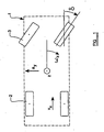
- a motor vehicle 1 is shown schematically, the vehicle 1 having a pair of rear wheels 2 and a pair of front wheels 3.
- Figure 1 illustrates various parameters which may be sensed in one embodiment of the invention.
- the vehicle may have a longitudinal velocity v x which is the normal speed of the vehicle.
- the vehicle may also have a lateral acceleration a y , and such an acceleration may be generated in a side impact situation or, alternatively, if the vehicle makes a sharp or high speed turn.
- the vehicle may have an angular velocity about a vertical axis z passing through the centre of the vehicle, ⁇ z . This angular rotation may be termed "yaw".
- the vehicle has, at any instant, a "steering angle", the steering angle ⁇ , being the angle between the rolling direction of the front wheels 3 of the vehicle and the longitudinal axis of the vehicle.
- the vehicle 1 may be subjected to a lateral or side slip situation when the front wheels 3 and/or the real wheels 2 are slipping in a lateral direction, for instance as a result of under-steering or over-steering of the vehicle 1.
- a slip situation also occurs when the vehicle 1 is subjected to body slip, whereby the body of the vehicle 1 slips in a lateral direction.
- Figure 2 illustrates a plurality of sensors which are provided to sense the various parameters identified with reference to Figure 1 .
- a sensor 4 is provided to sense longitudinal velocity v x .
- a sensor 5 is provided to determine the angular velocity ⁇ z (or "yaw") about the vertical axis z.
- a sensor 6 is provided to determine the steering angle ⁇ .
- a sensor 7 is provided to determine lateral acceleration ay.
- the signals from various combinations of sensors are passed to a central system in which the signals are processed by processors to produce outputs representative of various "handling conditions" or "vehicle dynamic severity conditions" of the vehicle.
- the signals are processed to determine how the vehicle is being driven, whether slowly or quickly, whether cornering or straight, whether with sharp or high speed corners, to enable a determination to be made of whether there is a risk or probability of an accident occurring.
- a processor 9 determines a function (f o/u ) of v x , ⁇ z and ⁇ , the function (f o/u ) being a function which indicates the degree of over-steer or under-steer.
- the processor 9 performs a complex process on the inputs that it receives from three of the sensors, namely the sensors 4, 5 and 6 as described above, to produce an output which is effectively indicative of the degree of under-steer or the degree of over-steer. It is to be understood that the output indicative of the degree of under-steer or over-steer is to be used to indicate the degree of lateral slip of the vehicle 1.
- the processor 10 determines a function (f bs ) of v x , ⁇ z and a y , the function (f bs ) being a function which indicates the degree of body slip.
- the processor 10 performs a complex process on the input that it receives from three of the sensors, namely the sensors 4, 5 and 7 to produce an output which is, effectively, an indication of the degree of side slip of the vehicle.
- the processor 11 determines a function (f em ) of v x and ⁇ , the function (f em ) being in the form which indicates the degree of evasive manoeuvring of the motor vehicle.
- the function is actually a function which involves not only ⁇ , but the first differential of ⁇ with regard to time, that differential being determined within the processor 11.
- the processor 11 forms a complex process on the inputs that it receives from two of the sensors, namely the sensors 4 and 6 to provide an output which is an effective indication of the degree of evasive manoeuvring being performed.
- the degree of evasive manoeuvring is related to the lateral slip of the vehicle 1, and it is to be understood that the output indicative of the degree of evasive manoeuvring is to be used to indicate the expected slip of the vehicle 1.
- the processor 13 determines a function (f hsc ) of v x and a y , the function (f hsc ) being in a form which indicates high speed cornering of the vehicle.
- the processor 13 performs a complex process on the input that it receives from two of the sensors, namely the sensors 4 and 7, to produce an output which is effectively an indication of the degree of high speed cornering that is being experienced by the vehicle. If the vehicle 1 is experiencing high speed cornering the vehicle 1 may undergo lateral slip and it is to be understood that the output from the sensors 4 and 7 which is indicative of the degree of high speed cornering is to be used to indicate the expected slip of the vehicle 1.
- the arrangement thus far described, thus produces a plurality of signals, each of which are indicative of a "handling condition” or a "slip condition” of the vehicle.
- the signals have a low value when the vehicle is being driven slowly and carefully, and a high value when the vehicle is being driven in a potentially dangerous manner.
- the discriminator 14 effectively determines which of the input signals from the processors 9 to 13 has the highest absolute value
- the discriminator 14 produces an output which is the absolute value of the function (f i ), that is to say the numerical value of the function regardless of whether the numerical value is positive or negative.
- the discriminator 14 may combine the signals from the various processors 9 to 13, to provide a complex function which indicates the degree of lateral slip or the expected degree of lateral slip of the vehicle 1 which is also indicative of overall probability or risk of an accident occurring. In determining the complex function other data may be used than simply the outputs fo the processors 9 to 13, such as, for example, the speed of the vehicle as sensed by the sensor 4.
- the output of the discriminator 14 is provided to a comparator 15.
- the comparator 15 includes at least one threshold.
- the purpose of the comparator 15 is to provide an output when the function from the discriminator 14 exceeds a first threshold, and also to respond to a further increase in the function.
- the output of the comparator is provided to a force level selector 16.
- the force level selector 16 controls an electric motor 17 which is incorporated within a seat-belt retractor 19, to wind-in seat-belt until a predetermined tension is achieved.
- the tension in the seat-belt is increased when the first threshold is crossed, and is also increased in response to each of a plurality of further increases in the function, as each of the remaining four thresholds are passed.
- the seat-belt is tensioned by the retractor in dependence on the magnitude of the function, with the level of tension increasing with an increasing value of the function (f i ).
- the processors 9 to 13, the discriminator 14, the comparator 15 and the selector 16 together form a control system to control the pretensioner.
- the control system generates a plurality of slip functions from a plurality of sensed parameters.
- the tension level applied to the seat-belt is selected in response to the value of the largest of the functions.
- the force level selector can be configured to select a force level or tension in the seat-belt which is directly proportional to the magnitude of the function, once the function has exceeded a first lower threshold, with the seat-belt tension thus rising smoothly until a maximum tension is obtained rather than in a step-wise fashion.
- control function is exerted through the medium of a function selected from a plurality of functions derived from a plurality of processors, each of which effectively generates a signal indicative of a particular slip function or handling characteristic of a vehicle
- the output of the processor 9 which indicates the degree of over-steer or under-steer, is passed directly to the comparator 15 which compares the degree of under-steer and over-steer with a plurality of thresholds (as will be described further with reference to Figure 3 ) and which passes a signal to the force level selector 16 to cause the retractor to be tensioned.
- the various sensors will sense parameters which are not directly related to an accident situation, but, by sensing the parameters, it is possible to determine when an accident is likely to occur, and, taking into account parameters such as the velocity of the vehicle v x at that instant, it is possible to determine the probable severity of the accident.
- the seat-belt may be retracted into the retractor. If the situation is such that there is a low risk of the vehicle going out of control, then the seat-belt may be tensioned gently.
- the seat-belt may be tensioned, by the retractor, to a higher degree, which may provide some slight discomfort to the person wearing the seat-belt, (or may even injure the person - especially if the person suffers from osteoporosis or brittle bone syndrome) but which will ensure that the seat-belt is in the optimum condition for providing protection to the person wearing the seat-belt should the anticipated severe accident occur.
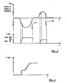
- the upper graphical figure is a graph showing the output of the processor 9, that is to say the processor that provides the function (f o/u ) which indicates the degree of over-steering or under-steering.
- the graph shows five predetermined thresholds for under-steer and over-steer. It can be seen that initially there is a substantial degree of under-steer. As the degree of under-steer exceeds the first threshold, the tensioner motor 17 is actuated to wind in seat-belt until there is a tension F, and it can be seen that the tension in the safety-belt is 50 N. Subsequently the second threshold is crossed, and the tension rises to 75 N. As the third threshold is crossed the tension rises to 100 N and as the fourth and fifth thresholds are crossed the applied force rises to 125 and 150 N respectively. The degree of under-steer continues to increase, but the maximum tension of 150 N is maintained.
- the various thresholds are passed, until finally the first threshold is passed.
- the maximum tension is maintained, however, as all of these thresholds are passed and then for an additional predetermined period of time, as indicated by the short arrow 21. This is to ensure that tension is not released prematurely in a complex accident situation.
- the tension in the seat-belt increases with incremental step increases as each threshold is passed. It is possible in a modified embodiment of the invention for the tension to be applied in a "smoother" manner, with the initial “soft" tension in the seat-belt being applied, once a first threshold has been exceeded.
- the selector 16 may provide an output when a first threshold is exceeded, the output of the selector then rising in a predetermined manner in response to any further rise in the value of the function.
- the tension in the seat-belt may be effectively proportional to the magnitude of the relative function until a second threshold or maximum possible applied force has been achieved.
- the applied force will then be maintained at the maximum level again until a predetermined period of time has elapsed following the reduction in the function to a level beneath the first threshold. This is illustrated in solid lines in Figure 4 , with the corresponding "step" function being shown in dotted lines.
- a retractor that forms part of an embodiment of the invention may additionally be provided with a conventional pretensioner actuated by a pyrotechnic charge, responsive to an accident sensor, to be actuated in case an accident should occur which is not sensed by sensors described above.
- pretensioner Whilst the invention has been described with reference to embodiments in which the pretensioner is incorporated into a retractor, other types of pretensioner may be used.
- control system may be configured so that whenever the seat-belt is in use and the vehicle is in use, tension will be applied to the seat-belt by the tensioner motor 17, so that the seat-belt is never “slack” but always gently restrains a seat occupant within the seat.
- the tension applied to the seat-belt by the tensioner motor will increase, under the control of the control system, in response to a potential "accident" situation, as described above.
Landscapes
- Engineering & Computer Science (AREA)
- Mechanical Engineering (AREA)
- Automotive Seat Belt Assembly (AREA)
- Control Of Transmission Device (AREA)
Applications Claiming Priority (2)
| Application Number | Priority Date | Filing Date | Title |
|---|---|---|---|
| GB0507089A GB2424983A (en) | 2005-04-07 | 2005-04-07 | Seatbelt pretensioner control system |
| PCT/SE2006/000403 WO2006107260A1 (en) | 2005-04-07 | 2006-04-04 | A seat-belt pretensioner arrangement |
Publications (3)
| Publication Number | Publication Date |
|---|---|
| EP1866191A1 EP1866191A1 (en) | 2007-12-19 |
| EP1866191A4 EP1866191A4 (en) | 2010-09-01 |
| EP1866191B1 true EP1866191B1 (en) | 2012-05-02 |
Family
ID=34586873
Family Applications (1)
| Application Number | Title | Priority Date | Filing Date |
|---|---|---|---|
| EP06717082A Expired - Lifetime EP1866191B1 (en) | 2005-04-07 | 2006-04-04 | A seat-belt pretensioner arrangement |
Country Status (8)
| Country | Link |
|---|---|
| US (1) | US7624833B2 (https=) |
| EP (1) | EP1866191B1 (https=) |
| JP (1) | JP4891988B2 (https=) |
| KR (1) | KR101267507B1 (https=) |
| CN (1) | CN101171159B (https=) |
| AT (1) | ATE555950T1 (https=) |
| GB (1) | GB2424983A (https=) |
| WO (1) | WO2006107260A1 (https=) |
Cited By (1)
| Publication number | Priority date | Publication date | Assignee | Title |
|---|---|---|---|---|
| EP3647127A1 (en) * | 2018-10-29 | 2020-05-06 | Toyota Jidosha Kabushiki Kaisha | Control device for vehicle seat belt |
Families Citing this family (15)
| Publication number | Priority date | Publication date | Assignee | Title |
|---|---|---|---|---|
| US8068956B2 (en) * | 2004-12-23 | 2011-11-29 | Daimler Ag | Restraining device for an occupant of a vehicle |
| GB2424982A (en) * | 2005-04-07 | 2006-10-11 | Autoliv Dev | Seatbelt pretensioner dependent on steering rate |
| GB2424983A (en) | 2005-04-07 | 2006-10-11 | Autoliv Dev | Seatbelt pretensioner control system |
| JP4299331B2 (ja) | 2006-12-06 | 2009-07-22 | 本田技研工業株式会社 | 車両のシートベルト装置 |
| DE102007017669B4 (de) * | 2007-04-14 | 2020-04-23 | Bayerische Motoren Werke Aktiengesellschaft | Sicherheitsgurtanordnung |
| JP4876028B2 (ja) * | 2007-05-30 | 2012-02-15 | 本田技研工業株式会社 | 車両のシートベルト装置 |
| US9120855B2 (en) | 2010-02-10 | 2015-09-01 | Novartis Ag | Biologic compounds directed against death receptor 5 |
| GB201105279D0 (en) | 2011-03-29 | 2011-05-11 | Jaguar Cars | Control of active vehicle device |
| FR2987015B1 (fr) * | 2012-02-17 | 2015-02-20 | Peugeot Citroen Automobiles Sa | Systeme de protection des passagers d'un vehicule et procede de mise en œuvre d'un tel systeme en situation de survirage ou de sous-virage |
| EP2650177B1 (en) * | 2012-04-10 | 2016-07-06 | Autoliv Development AB | Method for triggering a motorized retractor for a safety belt system of a vehicle |
| US8960724B2 (en) | 2013-03-15 | 2015-02-24 | Autoliv Asp, Inc. | Controlled pressure release for seatbelt pretensioning devices |
| EP2808206B1 (en) * | 2013-05-27 | 2017-07-12 | Volvo Car Corporation | Method and system of a vehicle for reversible seat belt retraction |
| EP3636497B1 (en) * | 2018-10-12 | 2021-05-19 | Toyota Jidosha Kabushiki Kaisha | Occupant restraint system for vehicle |
| CN109515380B (zh) * | 2018-11-26 | 2021-02-05 | 爱驰汽车有限公司 | 安全带预紧控制方法、系统、设备及存储介质 |
| JP7172941B2 (ja) | 2019-10-07 | 2022-11-16 | トヨタ自動車株式会社 | 車両用乗員拘束システム |
Family Cites Families (48)
| Publication number | Priority date | Publication date | Assignee | Title |
|---|---|---|---|---|
| JP2946995B2 (ja) * | 1993-03-31 | 1999-09-13 | 日産自動車株式会社 | 乗物用シートベルト装置 |
| US5605202A (en) * | 1995-06-07 | 1997-02-25 | Itt Automotive, Inc. | Apparatus and method for enhancing performance of an occupant restraint system in a vehicle |
| JP4142750B2 (ja) * | 1995-09-08 | 2008-09-03 | タカタ株式会社 | 車両の乗員拘束保護システム |
| US5765774A (en) * | 1996-04-05 | 1998-06-16 | Takata Corporation | Seat belt retractor employing ultrasonic motor |
| SE9604671L (sv) * | 1996-12-19 | 1998-06-20 | Volvo Ab | Säkerhetsanordning för fordon |
| GB2373220B (en) * | 1997-12-16 | 2002-11-13 | Nsk Ltd | Automotive passenger restraint and protection apparatus |
| US6257363B1 (en) * | 1997-12-16 | 2001-07-10 | Nsk Ltd. | Automotive passenger restraint and protection apparatus |
| US6626463B1 (en) * | 1998-09-22 | 2003-09-30 | Nsk Autoliv Co., Ltd. | Seatbelt device |
| DE19957802A1 (de) * | 1999-12-01 | 2001-06-07 | Trw Repa Gmbh | Gurtaufrollersystem |
| DE10005010C2 (de) * | 2000-02-04 | 2002-11-21 | Daimler Chrysler Ag | Verfahren und Sicherheits-Rückhalteeinrichtung zum Zurückhalten eines Insassen auf einem Fahrzeugsitz |
| US6539299B2 (en) | 2000-02-18 | 2003-03-25 | Optimum Power Technology | Apparatus and method for calibrating an engine management system |
| DE10010633A1 (de) * | 2000-03-03 | 2001-09-06 | Siemens Ag | Verfahren zum Erkennen einer Rollover-Situation |
| US6726249B2 (en) * | 2000-05-26 | 2004-04-27 | Takata Corporation | Motorized seat belt retractor |
| DE10029061C2 (de) * | 2000-06-13 | 2003-12-11 | Breed Automotive Tech | Rückhaltevorrichtung |
| US7132937B2 (en) * | 2000-09-25 | 2006-11-07 | Ford Global Technologies, Llc | Wheel lift identification for an automotive vehicle using passive and active detection |
| DE10061040A1 (de) * | 2000-12-08 | 2002-06-13 | Daimler Chrysler Ag | Verfahren zur Ansteuerung eines reversiblen Gurtstraffers |
| US6906621B2 (en) * | 2001-02-06 | 2005-06-14 | Mazda Motor Corporation | Occupant protection system for vehicle |
| DE10121386C1 (de) * | 2001-05-02 | 2002-08-29 | Daimler Chrysler Ag | Verfahren zum Ansteuern eines reversiblen Insassenschutzmittels in einem Kraftfahrzeug |
| JP3714207B2 (ja) * | 2001-07-27 | 2005-11-09 | 日産自動車株式会社 | 乗員拘束装置 |
| US7107136B2 (en) * | 2001-08-29 | 2006-09-12 | Delphi Technologies, Inc. | Vehicle rollover detection and mitigation using rollover index |
| JP3601511B2 (ja) * | 2001-12-18 | 2004-12-15 | トヨタ自動車株式会社 | シートベルト装置 |
| JP4317032B2 (ja) * | 2002-03-19 | 2009-08-19 | オートモーティブ システムズ ラボラトリー インコーポレーテッド | 車両ロールオーバ検出システム |
| CN100352703C (zh) * | 2002-03-19 | 2007-12-05 | 汽车系统实验室公司 | 车辆倾翻检测系统 |
| US6629575B2 (en) * | 2002-04-24 | 2003-10-07 | Dimitar Nikolov | Vehicle occupant emergency system |
| DE10229931A1 (de) * | 2002-07-04 | 2004-01-15 | Wanzl Metallwarenfabrik Gmbh | Laufrolle für Einkaufs- und Transportwagen |
| DE10230483A1 (de) * | 2002-07-06 | 2004-01-15 | Robert Bosch Gmbh | Verfahren zur Ansteuerung eines zweistufigen Gurtstraffers |
| JP3815420B2 (ja) * | 2002-10-24 | 2006-08-30 | トヨタ自動車株式会社 | 車両の乗員保護装置 |
| JP3912260B2 (ja) * | 2002-10-31 | 2007-05-09 | 日産自動車株式会社 | 車両用シートベルト装置 |
| JP3815428B2 (ja) * | 2002-12-05 | 2006-08-30 | トヨタ自動車株式会社 | 車両用シートベルト装置 |
| KR100521169B1 (ko) * | 2002-12-27 | 2005-10-12 | 현대자동차주식회사 | 롤 오버 제어 방법 |
| JP3926748B2 (ja) * | 2003-01-24 | 2007-06-06 | 本田技研工業株式会社 | シートベルト装置 |
| JP4242166B2 (ja) * | 2003-02-04 | 2009-03-18 | 本田技研工業株式会社 | シートベルト装置 |
| US7092808B2 (en) * | 2003-02-26 | 2006-08-15 | Ford Global Technologies, Llc | Integrated sensing system for an automotive system |
| DE10317640A1 (de) * | 2003-04-17 | 2004-11-04 | Robert Bosch Gmbh | Vorrichtung zur Ansteuerung von Rückhaltemitteln |
| JP3890477B2 (ja) | 2003-06-12 | 2007-03-07 | 日産自動車株式会社 | 車輌の横転判定方法及び車輌の横転判定装置 |
| US6915196B2 (en) * | 2003-09-23 | 2005-07-05 | Ford Global Technologies, Llc | Method for operating a vehicle crash safety system in a vehicle having a pre-crash sensing system and countermeasure systems |
| US7222007B2 (en) * | 2004-01-07 | 2007-05-22 | Ford Global Technologies, Llc | Attitude sensing system for an automotive vehicle relative to the road |
| US7162340B2 (en) * | 2004-01-08 | 2007-01-09 | Delphi Technologies, Inc. | Vehicle rollover detection and method of anticipating vehicle rollover |
| EP1720739B1 (de) * | 2004-03-01 | 2013-04-03 | Continental Teves AG & Co. oHG | Vorrichtung zum ermitteln einer kipptendenz |
| DE102004021174A1 (de) * | 2004-04-30 | 2005-11-24 | Daimlerchrysler Ag | Verfahren zum Steuern einer sicherheitsrelevanten Komponente eines Kraftfahrzeugs und Kraftfahrzeug mit einem präventiv auslösenden Sicherheitssystem |
| WO2006028895A1 (en) * | 2004-09-02 | 2006-03-16 | Tk Holdings Inc. | Motorized seat belt system |
| JP4614183B2 (ja) * | 2004-09-29 | 2011-01-19 | マツダ株式会社 | 車両のシートベルト装置 |
| US7715965B2 (en) * | 2004-10-15 | 2010-05-11 | Ford Global Technologies | System and method for qualitatively determining vehicle loading conditions |
| US7370721B2 (en) * | 2004-12-03 | 2008-05-13 | Autoliv Asp, Inc. | Seatbelt tensioning device and method |
| GB2424983A (en) | 2005-04-07 | 2006-10-11 | Autoliv Dev | Seatbelt pretensioner control system |
| JP2006306223A (ja) * | 2005-04-27 | 2006-11-09 | Toyota Motor Corp | ロールオーバ判定装置 |
| US7138938B1 (en) * | 2005-05-06 | 2006-11-21 | Ford Global Technologies, Llc | System and method for preemptively sensing an object and selectively operating both a collision countermeasure system and a parking assistance system aboard an automotive vehicle |
| JP2007276540A (ja) * | 2006-04-03 | 2007-10-25 | Honda Motor Co Ltd | 車両の乗員拘束装置 |
-
2005
- 2005-04-07 GB GB0507089A patent/GB2424983A/en not_active Withdrawn
-
2006
- 2006-04-04 WO PCT/SE2006/000403 patent/WO2006107260A1/en not_active Ceased
- 2006-04-04 KR KR1020077025764A patent/KR101267507B1/ko not_active Expired - Fee Related
- 2006-04-04 AT AT06717082T patent/ATE555950T1/de active
- 2006-04-04 EP EP06717082A patent/EP1866191B1/en not_active Expired - Lifetime
- 2006-04-04 JP JP2008505263A patent/JP4891988B2/ja not_active Expired - Lifetime
- 2006-04-04 CN CN2006800155186A patent/CN101171159B/zh not_active Expired - Fee Related
-
2007
- 2007-10-08 US US11/868,761 patent/US7624833B2/en not_active Expired - Lifetime
Cited By (1)
| Publication number | Priority date | Publication date | Assignee | Title |
|---|---|---|---|---|
| EP3647127A1 (en) * | 2018-10-29 | 2020-05-06 | Toyota Jidosha Kabushiki Kaisha | Control device for vehicle seat belt |
Also Published As
| Publication number | Publication date |
|---|---|
| CN101171159B (zh) | 2012-03-21 |
| US20080033616A1 (en) | 2008-02-07 |
| GB0507089D0 (en) | 2005-05-11 |
| EP1866191A4 (en) | 2010-09-01 |
| ATE555950T1 (de) | 2012-05-15 |
| US7624833B2 (en) | 2009-12-01 |
| CN101171159A (zh) | 2008-04-30 |
| JP2008535724A (ja) | 2008-09-04 |
| KR20070119733A (ko) | 2007-12-20 |
| JP4891988B2 (ja) | 2012-03-07 |
| WO2006107260A1 (en) | 2006-10-12 |
| EP1866191A1 (en) | 2007-12-19 |
| KR101267507B1 (ko) | 2013-05-23 |
| GB2424983A (en) | 2006-10-11 |
Similar Documents
| Publication | Publication Date | Title |
|---|---|---|
| US7624833B2 (en) | Seat-belt pretensioner arrangement | |
| JP3988600B2 (ja) | 乗員拘束システム | |
| US20060076178A1 (en) | Method for actuating a reversible vehicle occupant protection means in a motor vehicle | |
| US7894959B2 (en) | Method and device for actuating a passenger protection means | |
| KR20100095578A (ko) | 차량용 안전 수단을 제어하기 위한 방법 및 장치 | |
| US20080023246A1 (en) | Seat-Belt Pretensioner Arrangement | |
| US7912609B2 (en) | Motor vehicle comprising a preventive protective system | |
| CN108032856A (zh) | 一种主被动集成的多级预紧式安全带控制系统及其方法 | |
| JP2007536142A (ja) | 自動車の可逆ベルトプリテンショナの作動を制御する方法 | |
| US8275519B2 (en) | Motor vehicle having a preventatively acting safety system | |
| US20090150028A1 (en) | Motor vehicle with a safety system with a preventive action | |
| US20090024282A1 (en) | Method for a Preventive-Action Protection System In a Motor Vehicle Having an Inter-Vehicle Distance Sensor System | |
| US8335614B2 (en) | Method for controlling a belt pretensioner and safety arrangement comprising a belt pretensioner | |
| US20050021206A1 (en) | Method for obtaining triggering signals for passive safety devices of a motor vehicle from data of a vehicle dynamics control system | |
| US20080284243A1 (en) | Method for a Preventive-Action Protection System in a Motor Vehicle | |
| EP2650180B1 (en) | Method for triggering a motorized retractor for a safety belt system of a vehicle | |
| EP2650177B1 (en) | Method for triggering a motorized retractor for a safety belt system of a vehicle | |
| JP2006298315A (ja) | 運転支援システム | |
| DE102014018946B4 (de) | Vorrichtung und Verfahren zur Ansteuerung zumindest einer reversiblen Insassenschutzvorrichtung |
Legal Events
| Date | Code | Title | Description |
|---|---|---|---|
| PUAI | Public reference made under article 153(3) epc to a published international application that has entered the european phase |
Free format text: ORIGINAL CODE: 0009012 |
|
| 17P | Request for examination filed |
Effective date: 20070924 |
|
| AK | Designated contracting states |
Kind code of ref document: A1 Designated state(s): AT BE BG CH CY CZ DE DK EE ES FI FR GB GR HU IE IS IT LI LT LU LV MC NL PL PT RO SE SI SK TR |
|
| DAX | Request for extension of the european patent (deleted) | ||
| A4 | Supplementary search report drawn up and despatched |
Effective date: 20100729 |
|
| RIC1 | Information provided on ipc code assigned before grant |
Ipc: B60R 21/013 20060101AFI20100723BHEP |
|
| REG | Reference to a national code |
Ref country code: DE Ref legal event code: R079 Ref document number: 602006029234 Country of ref document: DE Free format text: PREVIOUS MAIN CLASS: B60R0022340000 Ipc: B60R0021013000 |
|
| GRAP | Despatch of communication of intention to grant a patent |
Free format text: ORIGINAL CODE: EPIDOSNIGR1 |
|
| RIC1 | Information provided on ipc code assigned before grant |
Ipc: B60R 21/013 20060101AFI20110930BHEP |
|
| GRAS | Grant fee paid |
Free format text: ORIGINAL CODE: EPIDOSNIGR3 |
|
| GRAA | (expected) grant |
Free format text: ORIGINAL CODE: 0009210 |
|
| AK | Designated contracting states |
Kind code of ref document: B1 Designated state(s): AT BE BG CH CY CZ DE DK EE ES FI FR GB GR HU IE IS IT LI LT LU LV MC NL PL PT RO SE SI SK TR |
|
| REG | Reference to a national code |
Ref country code: GB Ref legal event code: FG4D |
|
| REG | Reference to a national code |
Ref country code: CH Ref legal event code: EP Ref country code: AT Ref legal event code: REF Ref document number: 555950 Country of ref document: AT Kind code of ref document: T Effective date: 20120515 |
|
| REG | Reference to a national code |
Ref country code: IE Ref legal event code: FG4D |
|
| REG | Reference to a national code |
Ref country code: SE Ref legal event code: TRGR |
|
| REG | Reference to a national code |
Ref country code: DE Ref legal event code: R096 Ref document number: 602006029234 Country of ref document: DE Effective date: 20120628 |
|
| REG | Reference to a national code |
Ref country code: NL Ref legal event code: VDEP Effective date: 20120502 |
|
| REG | Reference to a national code |
Ref country code: LT Ref legal event code: MG4D Effective date: 20120502 |
|
| PG25 | Lapsed in a contracting state [announced via postgrant information from national office to epo] |
Ref country code: LT Free format text: LAPSE BECAUSE OF FAILURE TO SUBMIT A TRANSLATION OF THE DESCRIPTION OR TO PAY THE FEE WITHIN THE PRESCRIBED TIME-LIMIT Effective date: 20120502 Ref country code: CY Free format text: LAPSE BECAUSE OF FAILURE TO SUBMIT A TRANSLATION OF THE DESCRIPTION OR TO PAY THE FEE WITHIN THE PRESCRIBED TIME-LIMIT Effective date: 20120502 Ref country code: FI Free format text: LAPSE BECAUSE OF FAILURE TO SUBMIT A TRANSLATION OF THE DESCRIPTION OR TO PAY THE FEE WITHIN THE PRESCRIBED TIME-LIMIT Effective date: 20120502 Ref country code: IS Free format text: LAPSE BECAUSE OF FAILURE TO SUBMIT A TRANSLATION OF THE DESCRIPTION OR TO PAY THE FEE WITHIN THE PRESCRIBED TIME-LIMIT Effective date: 20120902 Ref country code: PL Free format text: LAPSE BECAUSE OF FAILURE TO SUBMIT A TRANSLATION OF THE DESCRIPTION OR TO PAY THE FEE WITHIN THE PRESCRIBED TIME-LIMIT Effective date: 20120502 |
|
| REG | Reference to a national code |
Ref country code: AT Ref legal event code: MK05 Ref document number: 555950 Country of ref document: AT Kind code of ref document: T Effective date: 20120502 |
|
| PG25 | Lapsed in a contracting state [announced via postgrant information from national office to epo] |
Ref country code: SI Free format text: LAPSE BECAUSE OF FAILURE TO SUBMIT A TRANSLATION OF THE DESCRIPTION OR TO PAY THE FEE WITHIN THE PRESCRIBED TIME-LIMIT Effective date: 20120502 Ref country code: GR Free format text: LAPSE BECAUSE OF FAILURE TO SUBMIT A TRANSLATION OF THE DESCRIPTION OR TO PAY THE FEE WITHIN THE PRESCRIBED TIME-LIMIT Effective date: 20120803 Ref country code: LV Free format text: LAPSE BECAUSE OF FAILURE TO SUBMIT A TRANSLATION OF THE DESCRIPTION OR TO PAY THE FEE WITHIN THE PRESCRIBED TIME-LIMIT Effective date: 20120502 Ref country code: PT Free format text: LAPSE BECAUSE OF FAILURE TO SUBMIT A TRANSLATION OF THE DESCRIPTION OR TO PAY THE FEE WITHIN THE PRESCRIBED TIME-LIMIT Effective date: 20120903 |
|
| PG25 | Lapsed in a contracting state [announced via postgrant information from national office to epo] |
Ref country code: BE Free format text: LAPSE BECAUSE OF FAILURE TO SUBMIT A TRANSLATION OF THE DESCRIPTION OR TO PAY THE FEE WITHIN THE PRESCRIBED TIME-LIMIT Effective date: 20120502 |
|
| PG25 | Lapsed in a contracting state [announced via postgrant information from national office to epo] |
Ref country code: CZ Free format text: LAPSE BECAUSE OF FAILURE TO SUBMIT A TRANSLATION OF THE DESCRIPTION OR TO PAY THE FEE WITHIN THE PRESCRIBED TIME-LIMIT Effective date: 20120502 Ref country code: EE Free format text: LAPSE BECAUSE OF FAILURE TO SUBMIT A TRANSLATION OF THE DESCRIPTION OR TO PAY THE FEE WITHIN THE PRESCRIBED TIME-LIMIT Effective date: 20120502 Ref country code: DK Free format text: LAPSE BECAUSE OF FAILURE TO SUBMIT A TRANSLATION OF THE DESCRIPTION OR TO PAY THE FEE WITHIN THE PRESCRIBED TIME-LIMIT Effective date: 20120502 Ref country code: RO Free format text: LAPSE BECAUSE OF FAILURE TO SUBMIT A TRANSLATION OF THE DESCRIPTION OR TO PAY THE FEE WITHIN THE PRESCRIBED TIME-LIMIT Effective date: 20120502 Ref country code: NL Free format text: LAPSE BECAUSE OF FAILURE TO SUBMIT A TRANSLATION OF THE DESCRIPTION OR TO PAY THE FEE WITHIN THE PRESCRIBED TIME-LIMIT Effective date: 20120502 Ref country code: SK Free format text: LAPSE BECAUSE OF FAILURE TO SUBMIT A TRANSLATION OF THE DESCRIPTION OR TO PAY THE FEE WITHIN THE PRESCRIBED TIME-LIMIT Effective date: 20120502 Ref country code: AT Free format text: LAPSE BECAUSE OF FAILURE TO SUBMIT A TRANSLATION OF THE DESCRIPTION OR TO PAY THE FEE WITHIN THE PRESCRIBED TIME-LIMIT Effective date: 20120502 |
|
| PG25 | Lapsed in a contracting state [announced via postgrant information from national office to epo] |
Ref country code: IT Free format text: LAPSE BECAUSE OF FAILURE TO SUBMIT A TRANSLATION OF THE DESCRIPTION OR TO PAY THE FEE WITHIN THE PRESCRIBED TIME-LIMIT Effective date: 20120502 |
|
| PLBE | No opposition filed within time limit |
Free format text: ORIGINAL CODE: 0009261 |
|
| STAA | Information on the status of an ep patent application or granted ep patent |
Free format text: STATUS: NO OPPOSITION FILED WITHIN TIME LIMIT |
|
| 26N | No opposition filed |
Effective date: 20130205 |
|
| PG25 | Lapsed in a contracting state [announced via postgrant information from national office to epo] |
Ref country code: ES Free format text: LAPSE BECAUSE OF FAILURE TO SUBMIT A TRANSLATION OF THE DESCRIPTION OR TO PAY THE FEE WITHIN THE PRESCRIBED TIME-LIMIT Effective date: 20120813 |
|
| REG | Reference to a national code |
Ref country code: DE Ref legal event code: R097 Ref document number: 602006029234 Country of ref document: DE Effective date: 20130205 |
|
| PG25 | Lapsed in a contracting state [announced via postgrant information from national office to epo] |
Ref country code: BG Free format text: LAPSE BECAUSE OF FAILURE TO SUBMIT A TRANSLATION OF THE DESCRIPTION OR TO PAY THE FEE WITHIN THE PRESCRIBED TIME-LIMIT Effective date: 20120802 |
|
| PG25 | Lapsed in a contracting state [announced via postgrant information from national office to epo] |
Ref country code: MC Free format text: LAPSE BECAUSE OF FAILURE TO SUBMIT A TRANSLATION OF THE DESCRIPTION OR TO PAY THE FEE WITHIN THE PRESCRIBED TIME-LIMIT Effective date: 20120502 |
|
| REG | Reference to a national code |
Ref country code: CH Ref legal event code: PL |
|
| REG | Reference to a national code |
Ref country code: IE Ref legal event code: MM4A |
|
| PG25 | Lapsed in a contracting state [announced via postgrant information from national office to epo] |
Ref country code: CH Free format text: LAPSE BECAUSE OF NON-PAYMENT OF DUE FEES Effective date: 20130430 Ref country code: LI Free format text: LAPSE BECAUSE OF NON-PAYMENT OF DUE FEES Effective date: 20130430 |
|
| PG25 | Lapsed in a contracting state [announced via postgrant information from national office to epo] |
Ref country code: IE Free format text: LAPSE BECAUSE OF NON-PAYMENT OF DUE FEES Effective date: 20130404 |
|
| PG25 | Lapsed in a contracting state [announced via postgrant information from national office to epo] |
Ref country code: TR Free format text: LAPSE BECAUSE OF FAILURE TO SUBMIT A TRANSLATION OF THE DESCRIPTION OR TO PAY THE FEE WITHIN THE PRESCRIBED TIME-LIMIT Effective date: 20120502 |
|
| PG25 | Lapsed in a contracting state [announced via postgrant information from national office to epo] |
Ref country code: LU Free format text: LAPSE BECAUSE OF NON-PAYMENT OF DUE FEES Effective date: 20130404 Ref country code: HU Free format text: LAPSE BECAUSE OF FAILURE TO SUBMIT A TRANSLATION OF THE DESCRIPTION OR TO PAY THE FEE WITHIN THE PRESCRIBED TIME-LIMIT; INVALID AB INITIO Effective date: 20060404 |
|
| REG | Reference to a national code |
Ref country code: FR Ref legal event code: PLFP Year of fee payment: 11 |
|
| REG | Reference to a national code |
Ref country code: FR Ref legal event code: PLFP Year of fee payment: 12 |
|
| REG | Reference to a national code |
Ref country code: FR Ref legal event code: PLFP Year of fee payment: 13 |
|
| PGFP | Annual fee paid to national office [announced via postgrant information from national office to epo] |
Ref country code: SE Payment date: 20220422 Year of fee payment: 17 Ref country code: GB Payment date: 20220425 Year of fee payment: 17 |
|
| REG | Reference to a national code |
Ref country code: SE Ref legal event code: EUG |
|
| GBPC | Gb: european patent ceased through non-payment of renewal fee |
Effective date: 20230404 |
|
| PG25 | Lapsed in a contracting state [announced via postgrant information from national office to epo] |
Ref country code: GB Free format text: LAPSE BECAUSE OF NON-PAYMENT OF DUE FEES Effective date: 20230404 |
|
| PG25 | Lapsed in a contracting state [announced via postgrant information from national office to epo] |
Ref country code: SE Free format text: LAPSE BECAUSE OF NON-PAYMENT OF DUE FEES Effective date: 20230405 Ref country code: GB Free format text: LAPSE BECAUSE OF NON-PAYMENT OF DUE FEES Effective date: 20230404 |
|
| PGFP | Annual fee paid to national office [announced via postgrant information from national office to epo] |
Ref country code: DE Payment date: 20240429 Year of fee payment: 19 |
|
| PGFP | Annual fee paid to national office [announced via postgrant information from national office to epo] |
Ref country code: FR Payment date: 20240430 Year of fee payment: 19 |
|
| REG | Reference to a national code |
Ref country code: DE Ref legal event code: R119 Ref document number: 602006029234 Country of ref document: DE |
|
| PG25 | Lapsed in a contracting state [announced via postgrant information from national office to epo] |
Ref country code: DE Free format text: LAPSE BECAUSE OF NON-PAYMENT OF DUE FEES Effective date: 20251104 |
|
| PG25 | Lapsed in a contracting state [announced via postgrant information from national office to epo] |
Ref country code: FR Free format text: LAPSE BECAUSE OF NON-PAYMENT OF DUE FEES Effective date: 20250430 |