EP1865594A2 - Steuerungsverfahren für einen Motor und Steuerung für einen Motor - Google Patents
Steuerungsverfahren für einen Motor und Steuerung für einen Motor Download PDFInfo
- Publication number
- EP1865594A2 EP1865594A2 EP07011394A EP07011394A EP1865594A2 EP 1865594 A2 EP1865594 A2 EP 1865594A2 EP 07011394 A EP07011394 A EP 07011394A EP 07011394 A EP07011394 A EP 07011394A EP 1865594 A2 EP1865594 A2 EP 1865594A2
- Authority
- EP
- European Patent Office
- Prior art keywords
- current
- value
- phase
- motor
- voltage command
- Prior art date
- Legal status (The legal status is an assumption and is not a legal conclusion. Google has not performed a legal analysis and makes no representation as to the accuracy of the status listed.)
- Withdrawn
Links
- 238000000034 method Methods 0.000 title claims abstract description 30
- 230000015654 memory Effects 0.000 description 20
- 102100033618 ATP-binding cassette sub-family A member 2 Human genes 0.000 description 11
- 101000801645 Homo sapiens ATP-binding cassette sub-family A member 2 Proteins 0.000 description 11
- 101000990566 Homo sapiens HEAT repeat-containing protein 6 Proteins 0.000 description 11
- 101000801684 Homo sapiens Phospholipid-transporting ATPase ABCA1 Proteins 0.000 description 11
- 102100033616 Phospholipid-transporting ATPase ABCA1 Human genes 0.000 description 11
- 238000010586 diagram Methods 0.000 description 10
- 238000005070 sampling Methods 0.000 description 8
- 239000011159 matrix material Substances 0.000 description 7
- 230000005856 abnormality Effects 0.000 description 5
- 238000001514 detection method Methods 0.000 description 4
- 230000006870 function Effects 0.000 description 4
- 101100272797 Caenorhabditis elegans icd-1 gene Proteins 0.000 description 3
- 230000009467 reduction Effects 0.000 description 3
- 244000145845 chattering Species 0.000 description 2
- 230000014509 gene expression Effects 0.000 description 2
- 230000007246 mechanism Effects 0.000 description 2
- 230000004048 modification Effects 0.000 description 2
- 238000012986 modification Methods 0.000 description 2
- 101100119059 Saccharomyces cerevisiae (strain ATCC 204508 / S288c) ERG25 gene Proteins 0.000 description 1
- 230000008901 benefit Effects 0.000 description 1
- 230000003247 decreasing effect Effects 0.000 description 1
- 230000005669 field effect Effects 0.000 description 1
- 230000004907 flux Effects 0.000 description 1
- 230000007935 neutral effect Effects 0.000 description 1
- 230000004043 responsiveness Effects 0.000 description 1
- 229920006395 saturated elastomer Polymers 0.000 description 1
- 239000004065 semiconductor Substances 0.000 description 1
Images





Classifications
-
- H—ELECTRICITY
- H02—GENERATION; CONVERSION OR DISTRIBUTION OF ELECTRIC POWER
- H02P—CONTROL OR REGULATION OF ELECTRIC MOTORS, ELECTRIC GENERATORS OR DYNAMO-ELECTRIC CONVERTERS; CONTROLLING TRANSFORMERS, REACTORS OR CHOKE COILS
- H02P6/00—Arrangements for controlling synchronous motors or other dynamo-electric motors using electronic commutation dependent on the rotor position; Electronic commutators therefor
- H02P6/08—Arrangements for controlling the speed or torque of a single motor
-
- H—ELECTRICITY
- H02—GENERATION; CONVERSION OR DISTRIBUTION OF ELECTRIC POWER
- H02P—CONTROL OR REGULATION OF ELECTRIC MOTORS, ELECTRIC GENERATORS OR DYNAMO-ELECTRIC CONVERTERS; CONTROLLING TRANSFORMERS, REACTORS OR CHOKE COILS
- H02P23/00—Arrangements or methods for the control of AC motors characterised by a control method other than vector control
- H02P23/14—Estimation or adaptation of motor parameters, e.g. rotor time constant, flux, speed, current or voltage
-
- H—ELECTRICITY
- H02—GENERATION; CONVERSION OR DISTRIBUTION OF ELECTRIC POWER
- H02P—CONTROL OR REGULATION OF ELECTRIC MOTORS, ELECTRIC GENERATORS OR DYNAMO-ELECTRIC CONVERTERS; CONTROLLING TRANSFORMERS, REACTORS OR CHOKE COILS
- H02P29/00—Arrangements for regulating or controlling electric motors, appropriate for both AC and DC motors
- H02P29/02—Providing protection against overload without automatic interruption of supply
- H02P29/032—Preventing damage to the motor, e.g. setting individual current limits for different drive conditions
Definitions
- the present invention relates to a control method and a controller for a motor, and more particularly to a control method and a controller for a motor with high reliability that can continuously control a motor when a failure or an abnormality is generated in one current detecting system and are most suitably applied to a control of an electric power steering.
- a control for a motor there is an electric power steering device in which a steering device for a vehicle is driven by controlling the motor torque as a steering assist force.
- the driving force of the motor is applied on a steering shaft or a rack shaft as the steering assist force by a transmitting mechanism such as a reduction gear using gear or a belt.
- a transmitting mechanism such as a reduction gear using gear or a belt.
- the feedback control of a motor current is carried out.
- the feedback controller adjusts a motor applied voltage so as to reduce a difference between a current command value and a motor current detected value.
- the motor applied voltage is ordinarily adjusted by adjusting the duty ratio of a Pulse Width Modulation (PWM) control.
- PWM Pulse Width Modulation
- a column shaft 2 of a steering wheel 1 is connected to a tie rod 6 of a steered wheel via a reduction gear 3, universal joints 4A and 4B and a rack and pinion mechanism 5.
- a torque sensor 10 is provided for detecting the steering torque of the steering wheel 1.
- a motor 20 for assisting the steering force of the steering wheel 1 is connected to the column shaft 2 through the reduction gear 3.
- a control unit 30 for controlling the power steering device an electric power is supplied from a battery 14 and an ignition key signal is inputted from an ignition key 11.
- the control unit 30 calculates a steering assist command value I as an assist command based on a steering torque T detected in the torque sensor 10 and a vehicle speed V detected in a vehicle speed sensor 12 and controls a current supplied to the motor 20 based on the calculated steering assist command value I.
- the control unit 30 is mainly comprised of a CPU (including an MPU or an MCU) and an ordinary function performed by a program in the CPU is shown in Fig. 12.
- the steering torque T detected in the torque sensor 10 and the vehicle speed V from the vehicle speed sensor or a Controller Area Network (CAN) are inputted to a current command value calculating part 31.
- the current command value calculating part 31 calculates a current command value Iref as a steering assist command based on the steering torque T and the vehicle speed V.
- the calculated current command value Iref is inputted to a three-phase current command value calculating part 32.
- a motor angle ⁇ and a motor angular velocity ⁇ are inputted to calculate current command values Ia to Ic of a to c phases.
- the current command values Ia to Ic are respectively inputted to a PI control part 34 so as to improve responsiveness via subtracting parts 33a to 33c.
- Voltage command values Da2, Db2 and Dc2 that are PI-controlled in the PI control part 34 are inputted to a PWM control part 35 for calculating a duty ratio.
- Gate driving signals G1 to G6 of the PWM calculated in the PWM control part 35 are inputted to an inverter circuit 36 to drive the three-phase motor 20A by the inverter circuit 36.
- a position sensor 37 such as a resolver is attached to the three-phase motor 20A.
- the motor angle ⁇ from the position sensor 37 is inputted to an angular velocity calculating part 38 and the motor angle ⁇ and the motor angular velocity ⁇ calculated in the angular velocity calculating part 38 are inputted to the three-phase current command value calculating part 32.
- three-phase motor current supplied to the motor 20A is detected as current detected values Iad to Icd.
- the current detected values Iad to Icd are respectively inputted to the subtracting parts 33a to 33c as the subtracter, and thus feedback is made.
- driving of the motor 20A is controlled by the current feedback control of the PWM based on the current command value Iref calculated in the current command value calculating part 31.
- FIG. 13 A detailed structural example of the inverter circuit 36 is shown in Fig. 13 and described.
- Driving of the three-phase motor 20A is controlled by turning on and off six field effect transistors (FET) FET1 to FET 6 connected to a three-phase bridge circuit and the FET 1 to FET6 are respectively controlled to be turned on and off by the gate driving signals G1 to G6 as PWM signals from the PWM control part 35.
- FET field effect transistors
- current detecting resistances Ra to Rc are connected and the voltage of the respective phases is inputted to a current detecting circuit 361 so that motor currents of the respective phases are detected and outputted as current detected values Iad to Icd.
- Patent Document 1 Japanese Patent Unexamined Publication No. 10-54852
- Patent Document 2 Japanese Patent No. 3674578
- a current value determining part is provided for switching and using a first current value composed of a value of the voltage drop of the current detecting resistance element of a prescribed phase as a current value of the prescribed phase and a second current value as a value obtained by reversing the sign of the sum of the voltage drop of the current detecting resistance elements of two remaining phases under a prescribed condition and the current value determining part uses the first current value as the current value of the phase in which the duty ratio of the arm elements in the lower stage is not smaller than a small value lower than 30 % and uses the second current value as the current value of the phase in which the duty ratio of the arm elements in the lower stage is smaller than the small value lower than 30 %.
- the current value of the phase in which the current cannot be accurately detected is calculated by using the current detected value of other phase.
- the current of (N-1) phases can be detected in an inverter of N (an integer of 2 or more) phases.
- means or a method thereof is not disclosed.
- specific means is not disclosed when a current detected value is not precise due to a failure.
- the present invention is devised in view of the above, and an object of the present invention is to provide a control method and a controller for a motor in which a current of at least (N-1) phases can be detected for a motor of N (an integer of 2 or more) phases, and even when the failure or the abnormality of a current detecting system of one phase is generated or the current detecting system of one phase is brought to an undetectable state, the current value of the phase of the failure or the phase of the undetectable state is estimated by specific means and a specific method by the use of the current detected value of other phase and a control is continuously carried out based on the estimated value and a controller for an electric power steering device using the controller for a motor.
- a control method for a motor that calculates a voltage command value based on a difference between a current command value and a current detected value and controls a PWM the voltage command value
- the control method comprises: detecting a failure or an undetectable state of a current detecting system; obtaining a current estimated value of a failure phase or an undetectable state phase based on the current detected value except the failure phase or the undetectable state phase when the failure or the undetectable state is detected; and continuously controlling the motor based on the current estimated value.
- the motor has N (an integer of 2 or more)phases and can detect a current of at least (N-1) phases.
- a third aspect of the present invention as set forth in the first aspect of the present invention, it may be adapted that the voltage command value is restricted and subsequently the motor is controlled by the PWM.
- a fourth aspect of the present invention as set forth in the first aspect of the present invention, it may be adapted that the failure or the undetectable state of the current detecting system is detected based on the voltage command value and an error between the current estimated value and the current detected value.
- a fifth aspect of the present invention as set forth in the first aspect of the present invention, it may be adapted that the control method of a motor is applied to an electric power steering for a vehicle.
- a controller for a motor that calculates a first voltage command value based on a difference between a current command value and a current detected value and controls a PWM based on the first voltage command value
- the controller comprises: a current estimating part that obtains a current estimated value based on the first voltage command value and the current detected value; and a current switching part that detects a failure or an undetectable state of a current detecting system by the current estimated value and the current detected value to output a feedback current detected value, wherein the feedback current detected value is set to be a current detected value for a difference, when the failure or the undetectable state is detected, the current estimated value of a failure phase or an undetectable state phase is obtained by using the current detected value except the failure phase or the undetectable state phase and the motor is continuously controlled based on the current estimated value.
- the controller further comprises a voltage command value restricting part that restricts the voltage command value, wherein a second voltage command value from the voltage command value restricting part is inputted to the current estimating part.
- the motor has N (an integer of 2 or more) phases and can detect a current of at least (N-1) phases.
- a controller for an electric power steering device that calculates a current command value in accordance with a steering torque and a vehicle speed and controls a motor having N (an integer of 2 or more) phases by a PWM based on a voltage command value, the motor applying an assist force to the steering device based on the current command value
- the controller comprises: a current estimating part that obtains a current estimated value based on the voltage command value and the current detected value of the motor; and a current switching part that switches a feedback current based on the current estimated value from the current estimating part and the current detected value.
- the current estimated value of a failure phase or an undetectable state phase is obtained by using the current detected value except the failure phase or the undetectable state phase and the motor is continuously controlled based on the current estimated value.
- the controller for an electric power steering device further comprises a voltage command value restricting part that restricts the voltage command value, wherein a restricted voltage command value from the voltage command value restricting part is inputted to the current estimating part.
- the motor has N (an integer of 2 or more) phases and can detect a current of at least (N-1) phases.
- the controller for the motor since the level of a voltage command value is restricted so that the current of at least (N-1) phases can be detected.
- the current of a phase that cannot be detected is estimated in accordance with prescribed expressions by using the current detected value of other phase and a control is continuously carried out by using the estimated current value, a motor control of high performance and high reliability can be realized.
- the control method and the controller for the motor according to the present invention are applied to the electric power steering, even if one current detecting system generates the failure, the abnormality or the undetectable state, a steering operation can be continuously controlled. Thus, the electric power steering device of high reliability and high performance can be provided.
- the present invention relates to a control method and a controller for a motor of N (an integer of 2 or more) phases and more particularly to a control method and a controller for an electric power steering device in which the levels of voltage command values of phases are respectively restricted so as to detect the current of at least (N-1) phases for a control system for controlling the motor of the N phases, and when a failure or an abnormality (hereinafter simply referred to as "failure") of a current detecting system is generated, the current of a phase that cannot be detected due to the failure is estimated from the current value of other phase in accordance with a prescribed expressions to continuously control the motor. Therefore, even when the current detecting system of one phase is failed or brought to an undetectable state, the control of the motor can be continuously carried out by a normal operation so that a control of high reliability and high performance can be realized.
- N an integer of 2 or more
- a state that the current cannot be precisely detected due to a duty ratio is discriminated from a state that the current cannot be detected due to the failure of a circuit.
- a case that the current cannot be precisely detected irrespective of the duty ratio by which the current can be detected is considered as the "failure” or the "abnormality", and a case that the duty ratio makes it impossible to precisely detect the current is considered as the "undetectable state”.
- Fig. 1 shows the structure of one embodiment of the present invention so as to correspond to that of Fig. 12.
- a voltage command value restricting part 40, a current estimating part 50, a current switching part 60 and a back electromotive force compensating part 70 are newly provided.
- voltage command values Da2, Db2 and Dc2 of three phases from a PI control part 34 are added to voltage compensated values Ea, Eb and Ec from the back electromotive force compensating part 70 and inputted to the voltage command value restricting part 40.
- the voltage command values Da21, Db21 and Dc21 restricted in the voltage command value restricting part 40 are inputted to a PWM control part 35 and inputted to the current estimating part 50 for estimating the current value of the motor of the current detecting system that is failed or brought to the undetectable state.
- Current estimated values Ia2e, Ib2e and Ic2e estimated in the current estimating part 50 are inputted to the current switching part 60.
- the current detected values Iad, Ibd and Icd of motor current of the phases respectively detected in a current detecting circuit 361 in an inverter circuit 36 are inputted to the current estimating part 50 and the current switching part 60.
- the voltage command value restricting part 40 restricts the level of voltage so that the current of at least two phases can be detected. The detailed structural examples of the voltage command value restricting part 40, the current estimating part 50 and the current switching part 60 will be described below.
- a compensation for a back electromotive force by the back electromotive force compensating part 70 relative to the voltage command values Da2, Db2 and Dc2 is carried out by a method as disclosed in, for instance, Japanese Patent Unexamined Publication No. 2005-199780 .
- the failure of the current detecting system such as a current detecting resistance or the current detecting circuit 361 is decided to be the "failure".
- the current switching part 60 obtains the error between the current detected values Iad to Icd and the current estimated values Ia2e to Ic2e for each phase.
- a three-phase current command value calculating part 32 calculates current command values Ia, Ib and Ic of respective phases in accordance with the current command value Iref, a motor angle ⁇ and a motor angular velocity ⁇ (step S5).
- the current switching part 60 calculates difference current values ⁇ Ia to ⁇ Ic between the current detected values Iad to Icd for the respective phases and the current estimated values Ia2e to Ic2e (step S6).
- the phase in which the absolute value of the difference current value ⁇ Ia to ⁇ Ic is larger than the prescribed value #1 is detected to store the phase in a memory ABC1 for observing the undetectable state (step S7). Further, the number of phases K is obtained in which the absolute value of the difference current value ⁇ Ia to ⁇ Ic is larger than the prescribed value #3 (> #1) and the voltage command values Da21 to Dc21 are not larger than the prescribed value #2 (step S10) .
- the current detecting system such as the current detecting resistance or the current detecting circuit 361 is considered to be failed.
- step S10 when the number of the phases K is equal 0, the procedure moves to an operation of step s20 shown in Fig. 3.
- a maximum value Dlimit of the voltage command value is set and store the phase decided to be failed in a memory ABC2 for observing the failure (step S11).
- step S12 a control is stopped (step S12).
- the voltage command value is liable to be saturated and a current controller including an integrator is liable to be wound up (see Fig.4A).
- the current command value Iref is desirably restricted.
- the half of battery voltage is ordinarily set to a neutral point voltage, that is, the control is carried out by considering the duty ratio of 50% to be a reference, however, when the maximum value Dlimit of the voltage command value is 90 %, the control is carried out by considering the duty ratio of 45 % to be a reference as shown in Fig.4B.
- the control may be stopped by making a determination at several times without making a determination at one time.
- the PI control part 34 calculates the voltage command values Da2, Db2 and Dc2 in accordance with difference current values Ia1 to Ic1 from the subtracting parts 33a to 33c.
- the voltage command values whose back electromotive force is compensated in the back electromotive force compensating part 70 and adding parts are inputted to the voltage command value restricting part 40 and the voltage command value restricting part 40 calculates the restricted voltage command values Da21, Db21 and Dc21 (step S21).
- the current estimating part 50 estimates currents at a next sampling time in accordance with the voltage command values Da21, Db21 and Dc21 and the current detected values Iad, Ibd and Icd (step S22).
- the PWM control part 35 outputs the gate signals G1 to G6 of PWM signals (step S23) to return to the step S2.
- the PI control part 34 calculates the voltage command values Da2, Db2 and Dc2 and the voltage command value restricting part 40 calculates the voltage command values Da21, Db21 and Dc21 (step S24) .
- the current estimating part 50 estimates currents at a next sampling time by using, only for the phase A, a value obtained by reversing the sign of the sum of the current detected values of other phases and the current detected values for other two phase (step S25), then go to the above-described step S23. Further, in the step S20, when it is decided that the number of the phases M is 2 or more (M ⁇ 2), any one of below-described (a) to (c) is selected to shift to the step S24 (step S26).
- the voltage command value restricting part 40 corrects the voltage command values Da2, Db2 and Dc2 so that the current of at least (N-1) phases can be normally detected.
- a structure may be formed that includes a detection threshold phase detecting part 43 for detecting that the two phases of the voltage command values Da2, Db2 and Dc2 simultaneously reach a detection threshold value or higher in detecting the current by a three-phase downstream shunt system to output a threshold detecting signal SL, an intermediate value output part 44 for outputting an intermediate value Mid of the voltage command values Da2, Db2 and Dc2 when the threshold detecting signal SL is outputted, a comparing part 46 for obtaining a difference DT between the intermediate value Mid and the threshold 45 of a prescribed duty and subtracting parts 42a to 42c for subtracting the difference DT respectively from the voltage command values Da2, Db2 and Dc2.
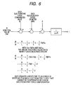
- a transfer function part shown in Fig. 6 An ordinary model of a motor is expressed by a transfer function part shown in Fig. 6.
- the discrete-time state equation of the motor is expressed as a below-described Eq.(1), where x is a state variable, A is a system matrix, B is an input matrix and C is an output matrix (for outputting a measurable state amount from the state variable x).
- x(k) is a state variable at a time kT 1
- x(k+1) is a state variable of a time (k+1) T 1 .
- a sign "over hat" expresses an estimated value. A difference between the estimated value and a real value is multiplied by a gain L and an obtained value is fed back so that the estimated value becomes close to the real value.
- the current detected values are used for the estimation.
- the current detected values of other phases are used to estimate a current using the observer expressed by the above-described Eq.(2).
- the current detecting systems of at least the (N-1) phases can detect the current, the observer is established. That is, when the current of the (N-1) phases cannot be detected, the current of remaining one phase cannot be obtained.
- the duty ratio may be adjusted or restricted so that the duty ratios of at least the (N-1) phases satisfy that condition.
- a final output restricted value is set to, for instance, a range of 0 to the prescribed value #2 instead a range of 0 to 100 %, so that the current of all the phases except the failed phase can be detected.
- the control can be continuously carried out. Accordingly, in the present invention, for the phase in which the current cannot be detected, the current estimated value is used.
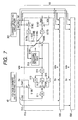
- Fig. 7 shows a detailed circuit of the current estimating part 50.
- a current estimating part 510 for a phase a shown by a dashed line is specifically described.
- the structures of a current estimating part 520 for a phase b and a current estimating part 530 for a phase c are the same as the structure of the current estimating part 510. Only the voltage command values Da21 to Dc 21, the current detected values Iad to Icd, the voltage compensated values Ea to Ec and the current estimated values Ia2e to Ic2e that are inputted are different. In the current estimating part 510 shown in Fig. 7, the Eq.
- a block 511 of the input matrix B shows that a difference between the voltage command value Da21 and the back electromotive force Ea is multiplied by the input matrix B and corresponds to Bu (k) of the Eq.(2).
- a block 513 shows a unit delay part for the delay of one sampling, where a block 512 is the system matrix A, a block 514 is the output matrix C and a block 515 is the gain L.
- the voltage compensated value Ea is subtracted from the voltage command value Da21 from the voltage command value restricting part 40 in the subtracting part 519E and inputted to the block 511.
- the current detected value Iad of one phase detected in the current detecting circuit 361 is inputted to a point 518A of the switching part 518.
- the current detected values Ibd and Icd of other phases are added in the adding part 519C, inverted in the inverting part 517A, and inputted to a point 518B of the switching part 518.
- the current estimated values Ib2e and Ic2e of other phases are added in the adding part 519D, inverted in the inverting part 517B and inputted to a point 518C of the switching part 518.
- the switching deciding part 516 switches the points 518A to 518C of the switching part 518 in accordance with the error between the current estimated value Ia2e and the current detected value Iad.
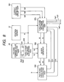
- Fig. 8 shows other structural instance (vector control) of the current estimating part 50, an estimation may be carried out on dq axes and the current may be controlled for each phase or on the dq axes.
- the vector control is a control that a q axis for controlling a torque as an axis of coordinate of a rotor magnet of the motor and a d axis for controlling the strength of a magnetic field are independently set and the axes are direct to each other.
- a dq axis current id and iq of the vector control is expressed as Eq. (3), where a resistance is R and an inductance is L.
- Eq. (3) indicates ⁇ 3/2 of the inter-linkage flux of an armature by a permanent magnet. Further, a model that considers a disturbance d is expressed as a below-described Eq. (4) and an estimated model of the form of Eq. (2) is obtained on the dq axes.
- the voltage command values Vd and Vq are inputted to a dq axis observer 560.
- the current values Iad, Ibd and Icd of the three phases detected in the current detecting circuit 361 are inputted to a three phase/two phase converting part 570.
- the motor angle ⁇ from a position sensor 37 is inputted to the three phase/two phase converting parts 540 and 570.
- the three phase/two phase converting part 570 outputs current values id and iq of two phases to input the current values to the dq axis observer 560.
- the three phase/two phase converting parts 540 and 570 are converted in accordance with a below-described Eq.(5).
- id and iq 2 3 ⁇ cos ⁇ cos ⁇ - 2 3 ⁇ ⁇ cos ( ⁇ + 2 3 ⁇ ⁇ ) - sin ⁇ - sin ( ⁇ - 2 3 ⁇ ⁇ ) - sin ( ⁇ + 2 3 ⁇ ⁇ ) [ i a i b i c ]
- the motor angle ⁇ is also inputted to a two phase/three phase converting part 550 and current estimated values Ia4e, Ib4e and Ic4e of three phases converted in the two phase/three phase converting part 550 are inputted to the three phase/two phase converting part 570.
- the three phase/two phase converting part 570 decides that the current detecting system is failed, and outputs the current estimated values Ia4e to Ic4e as feedback current Iad1 to Icd1.
- the two phase/three phase converting part 550 is converted in accordance with a below-described Eq.(6).
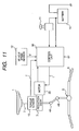
- FIG. 9 shows another embodiment of the present invention correspondingly to Fig. 1.
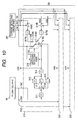
- voltage command values Da2 to Dc2 from a PI control part 34 are inputted to a current estimating part 50.
- the structure of the current estimating part 50 in this case is shown in Fig. 10. A similar control can be realized in this embodiment.
- the control of the three-phase motor is explained.
- the present invention may be similarly applied to a motor of two phases or more.
- the current estimated values are used as a feedback current, however, a value obtained by reversing the sign of the sum of the current detected values of other phases may be used as a feedback current.
- the prescribed value When the difference between the detected value and the estimated value is compared with the prescribed value, the prescribed value may be provided with a hysteresis. Since the current detected value has quantized noise, there is a fear that a chattering state is generated which needs to be frequently switched under the fixed prescribed value. To prevent the generation of the chattering state, the prescribed value is provided with the hysteresis.
- control method and the controller for the motor can be applied to the electric power steering device and a steering control of high performance and high reliability can be realized.
Landscapes
- Engineering & Computer Science (AREA)
- Power Engineering (AREA)
- Power Steering Mechanism (AREA)
- Steering Control In Accordance With Driving Conditions (AREA)
- Control Of Ac Motors In General (AREA)
Applications Claiming Priority (1)
| Application Number | Priority Date | Filing Date | Title |
|---|---|---|---|
| JP2006161297A JP4867483B2 (ja) | 2006-06-09 | 2006-06-09 | モータ制御方法及び制御装置 |
Publications (1)
| Publication Number | Publication Date |
|---|---|
| EP1865594A2 true EP1865594A2 (de) | 2007-12-12 |
Family
ID=38537630
Family Applications (1)
| Application Number | Title | Priority Date | Filing Date |
|---|---|---|---|
| EP07011394A Withdrawn EP1865594A2 (de) | 2006-06-09 | 2007-06-11 | Steuerungsverfahren für einen Motor und Steuerung für einen Motor |
Country Status (3)
| Country | Link |
|---|---|
| US (1) | US20070296375A1 (de) |
| EP (1) | EP1865594A2 (de) |
| JP (1) | JP4867483B2 (de) |
Cited By (2)
| Publication number | Priority date | Publication date | Assignee | Title |
|---|---|---|---|---|
| CN104205617A (zh) * | 2012-04-04 | 2014-12-10 | 日本精工株式会社 | 电动机控制装置及搭载其的电动助力转向装置 |
| US20220169307A1 (en) * | 2020-11-30 | 2022-06-02 | Steering Solutions Ip Holding Corporation | Input power health diagnostic for electric power steering |
Families Citing this family (13)
| Publication number | Priority date | Publication date | Assignee | Title |
|---|---|---|---|---|
| JP2008067556A (ja) * | 2006-09-11 | 2008-03-21 | Sanyo Electric Co Ltd | モータ制御装置 |
| JP5343955B2 (ja) * | 2009-12-25 | 2013-11-13 | 日本精工株式会社 | モータ制御装置及びそれを搭載した電動パワーステアリング装置 |
| JP2012130980A (ja) * | 2010-12-21 | 2012-07-12 | Makita Corp | コードレス電動工具 |
| US8473147B2 (en) * | 2011-03-23 | 2013-06-25 | GM Global Technology Operations LLC | State of health indicator for a vehicle fuel delivery system |
| CN103036529B (zh) | 2011-09-29 | 2017-07-07 | 株式会社大亨 | 信号处理装置、滤波器、控制电路、逆变器和转换器系统 |
| DK2575252T3 (en) | 2011-09-29 | 2018-10-08 | Daihen Corp | Signal processor, filter, power converter for power converter circuit, connection inverter system and PWM inverter system |
| US9998042B2 (en) * | 2013-03-04 | 2018-06-12 | Seagate Technology Llc | Torque disturbance cancellation for a motor |
| KR101566590B1 (ko) | 2013-11-29 | 2015-11-13 | 엘에스산전 주식회사 | 인버터 제어장치 |
| JP6583002B2 (ja) * | 2016-01-08 | 2019-10-02 | 富士通株式会社 | 電源回路、電源回路の異常検出プログラム及び電源回路の異常検出方法 |
| JP2017132346A (ja) * | 2016-01-27 | 2017-08-03 | 上銀科技股▲分▼有限公司 | ハンドル回転角度センサーの故障を検出するシステム |
| US10717463B2 (en) * | 2018-10-31 | 2020-07-21 | Steering Solutions Ip Holding Corporation | Feedforward control of permanent magnet synchronous motor drive under current sensing failure |
| JP7501342B2 (ja) * | 2020-12-11 | 2024-06-18 | ニデック株式会社 | モータの制御装置、制御方法、モータモジュールおよび電動パワーステアリング装置 |
| CN113241987B (zh) * | 2021-05-11 | 2022-12-20 | 广东美的白色家电技术创新中心有限公司 | 一种电机的控制方法、控制系统和存储介质 |
Family Cites Families (12)
| Publication number | Priority date | Publication date | Assignee | Title |
|---|---|---|---|---|
| JP2861680B2 (ja) * | 1992-10-13 | 1999-02-24 | 株式会社日立製作所 | 電気自動車用故障検出法及びそれを用いたフェールセイフ制御方法 |
| JP4187308B2 (ja) * | 1998-06-16 | 2008-11-26 | 日本オーチス・エレベータ株式会社 | 可変速駆動装置 |
| US6590362B2 (en) * | 2001-07-27 | 2003-07-08 | Texas A&M University System | Method and system for early detection of incipient faults in electric motors |
| JP4725011B2 (ja) * | 2003-11-14 | 2011-07-13 | 株式会社明電舎 | 永久磁石同期電動機のV/f制御装置 |
| JP4539218B2 (ja) * | 2004-08-02 | 2010-09-08 | 日本精工株式会社 | 電動パワーステアリング装置 |
| US7443642B2 (en) * | 2006-05-26 | 2008-10-28 | Pratt & Whitney Canada Corp. | Electric motor control |
| JP5070867B2 (ja) * | 2007-02-05 | 2012-11-14 | 株式会社ジェイテクト | モータ制御装置及び電動パワーステアリング装置 |
| US7990094B2 (en) * | 2007-06-20 | 2011-08-02 | Jtekt Corporation | Motor controller and electric power steering apparatus |
| JP2009055748A (ja) * | 2007-08-29 | 2009-03-12 | Sanyo Electric Co Ltd | 電流検出ユニット及びモータ制御装置 |
| JP5014034B2 (ja) * | 2007-09-12 | 2012-08-29 | オムロンオートモーティブエレクトロニクス株式会社 | 多相交流モータ駆動装置 |
| JP5057908B2 (ja) * | 2007-09-13 | 2012-10-24 | オムロンオートモーティブエレクトロニクス株式会社 | 多相交流モータ駆動装置 |
| JP2009081930A (ja) * | 2007-09-26 | 2009-04-16 | Jtekt Corp | モータ制御装置および電動パワーステアリング装置 |
-
2006
- 2006-06-09 JP JP2006161297A patent/JP4867483B2/ja active Active
-
2007
- 2007-06-08 US US11/760,494 patent/US20070296375A1/en not_active Abandoned
- 2007-06-11 EP EP07011394A patent/EP1865594A2/de not_active Withdrawn
Cited By (4)
| Publication number | Priority date | Publication date | Assignee | Title |
|---|---|---|---|---|
| CN104205617A (zh) * | 2012-04-04 | 2014-12-10 | 日本精工株式会社 | 电动机控制装置及搭载其的电动助力转向装置 |
| EP2835906A4 (de) * | 2012-04-04 | 2016-10-12 | Nsk Ltd | Motorsteuerungsvorrichtung und elektrische servolenkung damit |
| CN104205617B (zh) * | 2012-04-04 | 2017-09-05 | 日本精工株式会社 | 电动机控制装置及搭载其的电动助力转向装置 |
| US20220169307A1 (en) * | 2020-11-30 | 2022-06-02 | Steering Solutions Ip Holding Corporation | Input power health diagnostic for electric power steering |
Also Published As
| Publication number | Publication date |
|---|---|
| US20070296375A1 (en) | 2007-12-27 |
| JP4867483B2 (ja) | 2012-02-01 |
| JP2007330077A (ja) | 2007-12-20 |
Similar Documents
| Publication | Publication Date | Title |
|---|---|---|
| EP1865594A2 (de) | Steuerungsverfahren für einen Motor und Steuerung für einen Motor | |
| US8294407B2 (en) | Motor controller and electric power steering system | |
| EP2835906B1 (de) | Motorsteuerungsvorrichtung und elektrische servolenkung damit | |
| US8890459B2 (en) | Motor control device and electric power steering system | |
| US9050996B2 (en) | Control device for electric power steering apparatus | |
| CN102582679B (zh) | 电动助力转向装置 | |
| US9248852B2 (en) | Electric power steering system | |
| US7889978B2 (en) | Motor controller and electric power steering system | |
| JP4984598B2 (ja) | 電動パワーステアリング装置 | |
| US8272474B2 (en) | Electric power steering system | |
| CN101121414A (zh) | 电动转向设备 | |
| US10924046B2 (en) | Motor driven power steering apparatus and control method therefor | |
| EP2476590A1 (de) | Verfahren und vorrichtung zur diagnose eines stromversorgungsstatus | |
| US20090009127A1 (en) | Motor control device and electric power steering device using the same | |
| US20200395882A1 (en) | Electric power steering apparatus | |
| JP5168057B2 (ja) | 電動パワーステアリング装置 | |
| JP2009248962A (ja) | 電動パワーステアリング装置 | |
| JP2012116372A (ja) | 電動パワーステアリング装置 | |
| EP1712448B1 (de) | Elektrische servolenkvorrichtung | |
| JP5061536B2 (ja) | モータ制御装置及びこれを用いた電動パワーステアリング制御装置 | |
| KR102088720B1 (ko) | 전자 제어 장치 및 이를 이용한 전류 센서 이득 보상 방법 | |
| JP2020068614A (ja) | 制御装置 | |
| JP2010028971A (ja) | モータ駆動制御装置、及び電動パワーステアリング装置 |
Legal Events
| Date | Code | Title | Description |
|---|---|---|---|
| PUAI | Public reference made under article 153(3) epc to a published international application that has entered the european phase |
Free format text: ORIGINAL CODE: 0009012 |
|
| AK | Designated contracting states |
Kind code of ref document: A2 Designated state(s): AT BE BG CH CY CZ DE DK EE ES FI FR GB GR HU IE IS IT LI LT LU LV MC MT NL PL PT RO SE SI SK TR |
|
| AX | Request for extension of the european patent |
Extension state: AL BA HR MK YU |
|
| STAA | Information on the status of an ep patent application or granted ep patent |
Free format text: STATUS: THE APPLICATION HAS BEEN WITHDRAWN |
|
| 18W | Application withdrawn |
Effective date: 20090528 |