EP1865128B1 - Device for fixing a closing panel in the bottom of a rabbet of a column - Google Patents
Device for fixing a closing panel in the bottom of a rabbet of a column Download PDFInfo
- Publication number
- EP1865128B1 EP1865128B1 EP07350004A EP07350004A EP1865128B1 EP 1865128 B1 EP1865128 B1 EP 1865128B1 EP 07350004 A EP07350004 A EP 07350004A EP 07350004 A EP07350004 A EP 07350004A EP 1865128 B1 EP1865128 B1 EP 1865128B1
- Authority
- EP
- European Patent Office
- Prior art keywords
- fixing device
- post
- groove
- support face
- fixing
- Prior art date
- Legal status (The legal status is an assumption and is not a legal conclusion. Google has not performed a legal analysis and makes no representation as to the accuracy of the status listed.)
- Active
Links
- 239000002184 metal Substances 0.000 claims description 20
- 239000000463 material Substances 0.000 claims description 13
- 239000004033 plastic Substances 0.000 claims description 6
- 229920003023 plastic Polymers 0.000 claims description 6
- 238000004873 anchoring Methods 0.000 abstract 1
- 238000012423 maintenance Methods 0.000 abstract 1
- 238000009434 installation Methods 0.000 description 7
- 238000013016 damping Methods 0.000 description 3
- 229910000639 Spring steel Inorganic materials 0.000 description 2
- 239000011248 coating agent Substances 0.000 description 2
- 238000000576 coating method Methods 0.000 description 2
- 230000000694 effects Effects 0.000 description 2
- 238000000034 method Methods 0.000 description 2
- 230000035939 shock Effects 0.000 description 2
- 239000004952 Polyamide Substances 0.000 description 1
- 239000004698 Polyethylene Substances 0.000 description 1
- 238000004026 adhesive bonding Methods 0.000 description 1
- 230000000295 complement effect Effects 0.000 description 1
- 210000000887 face Anatomy 0.000 description 1
- 239000000835 fiber Substances 0.000 description 1
- 210000003128 head Anatomy 0.000 description 1
- 238000004519 manufacturing process Methods 0.000 description 1
- 239000003973 paint Substances 0.000 description 1
- 229920002647 polyamide Polymers 0.000 description 1
- -1 polyethylene Polymers 0.000 description 1
- 229920000573 polyethylene Polymers 0.000 description 1
- 238000003466 welding Methods 0.000 description 1
Images


Classifications
-
- E—FIXED CONSTRUCTIONS
- E04—BUILDING
- E04H—BUILDINGS OR LIKE STRUCTURES FOR PARTICULAR PURPOSES; SWIMMING OR SPLASH BATHS OR POOLS; MASTS; FENCING; TENTS OR CANOPIES, IN GENERAL
- E04H17/00—Fencing, e.g. fences, enclosures, corrals
- E04H17/14—Fences constructed of rigid elements, e.g. with additional wire fillings or with posts
- E04H17/16—Fences constructed of rigid elements, e.g. with additional wire fillings or with posts using prefabricated panel-like elements, e.g. wired frames
- E04H17/161—Fences constructed of rigid elements, e.g. with additional wire fillings or with posts using prefabricated panel-like elements, e.g. wired frames using wire panels
Definitions
- the invention relates to a device for fixing a fence panel in a rabbet of a pole.
- one or more horizontal or vertical ribs provide greater rigidity to the panel.
- the panel When the panels are subjected to shocks, for example, due to balloon strikes, the panel vibrates.
- the document FR 2698417 discloses a fastener having the features of the preamble of claim 1.
- the invention proposes to remedy these problems in particular.
- the subject of the invention is a device for fastening the vertical end wire of a lattice panel to the bottom of a U-shaped rebate of a post, said device comprising a body having a face support intended to come opposite the bottom of a rabbet of a post, this bearing face having a groove for capping the vertical wire, said body being made of plastic material in which is embedded the metal blade, a part of which is external to said body to form two resilient mounting flanges for engaging behind the stops that has the aforementioned rabbet.
- poles 1 and panels 2 welded mesh Referring to the drawing, we see that to erect a fence is used poles 1 and panels 2 welded mesh.
- Panel 2 consists of vertical and horizontal wires 2A 2B welded at each intersection.
- One or more horizontal ribs obtained by folding the panel can contribute to the rigidity of said panel.
- the posts have an H section so as to have two opposite rabbets 1A, 1B.
- the end post or corner post may have only one rabbet.
- the panel is simply wedged between two rabbets and held by a single device 3.
- a plurality of devices are thus used distributed along the longitudinal axis of the post.
- These devices act as a retaining flange of the vertical end wire 2C of a lattice panel on the bottom of a U-shaped rabbet.
- This fixing device comprises a bearing face 4 intended to come opposite and possibly bear against the bottom of a rabbet of a post.
- a passage 5 is often provided to receive a member 6 passing through the flange and the bottom 20 of the rabbet, this member being intended to permanently fix the flange in the bottom of the rabbet.
- One or two grooves 7 arranged in the support surface 4 allow the fixing device to cap the extreme vertical wire and place the contact surface of the flange in contact or at a short distance from the bottom 20 of the rabbet.
- the sections of the grooves are different so that the fastener can be used with panels whose wires are of different diameters, the diameter of the wire being chosen according to the desired resistance of the panel.
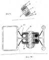
- the fixing device is placed temporarily and does not rest on the bottom of the rabbet ( figure 5 or 7 ) whereas figure 6 or 8 it is permanently placed and supported on the bottom 20 of the rabbet.
- the ends of the metal wings are no longer in contact with the abutments of the rabbet.
- the fastening device comprises two metal flanges 8 which, progressively diverging from the bearing face 4 towards the opposite face 9 of the flange, define a V whose opening is elastically deformable so that the free ends of these flanges said wings can cooperate with stops 10 presented by the lateral wings 11 of a rabbet 1A, 1B of the post to anchor the flange ( figure 5 ).
- the device is possibly fixed by a through member 6 (example of the figure 6 ).
- These wings 8 rise from each of the lateral faces 12 of the flange facing the wings 11 of the rabbet.
- the distance between the end of the V is greater than the distance between the two wings of the U of the rabbet.
- these stops can be obtained by a folded edge or by a spun rib or any other form to create a stop preventing removal of the flange.
- the fence installer can come to position these devices for eventually fix these permanently with safety bolts with self-breaking nuts, rivets or other type of through body.
- the passage 5 in the device is elongate with the largest axis in the direction of the longitudinal axis of the post, ie when the device is placed temporarily in the rabbet the major axis of the oblong light is aligned with the longitudinal axis of the pole.
- the length of the light along the major axis is substantially equal to twice the diameter of the screw. This allows to pre-drill the posts.
- the entrance of the passage made in the fixing device may include a cavity 14 adapted to house the screw head, this footprint having abutments rotating in rotation said head.
- the two metal wings 8 of the fixing device are the ends of a metal blade embedded in the body 3A of plastic material for example by overmolding around the metal blade or by assembling two complementary parts.
- the blade is shaped differently and has an arch capping the vertical wire.
- Cutouts 16 in the metal blade allow a good connection between this blade and the overmolded material which will preferably be a plastic material possibly reinforced with fibers.
- the body 3A of the fixing device is preferably overmolded on the metal blade. It could be made in two parts assembled according to a joint plane by gluing, ultrasonic welding or another method of assembly.
- the width of the metal blade will be less than the width of the body and it is spring steel.
- each metal wing is split into one or more parts by slots 30 in order to provide flexibility during installation.
- this plastic material body will be rigid or slightly elastically deformable to dampen noise and / or shock depending on its hardness. It may be, for example polyamide loaded (rigid material), polystyrene-butadiene-styrene (flexible and rubbery material) or polyethylene.
- the notches in the metal part may not be needed anymore but you will lose in strength and quality.
- these fins 50 appears especially in the eyes of the figure 7 which shows the device in temporary position, ie in a position such that the bearing surface 4 of the device is moved away from the bottom of the rabbet.
- the presence of these fins makes it possible to apply the selvedge wire on the bottom of the rabbet, which makes it possible to position the panel correctly with respect to the bottom of the rabbet.
- the height of these fins 50 is substantially equal to or even slightly greater than the distance between the bottom of the rabbet and the said support face of the fastener.
- fixation device When the fixation device is definitively fixed ( figure 8 ), then deformed flexible fins that will then serve as damping elements.
- FIG 10 Another solution is shown using a softer material for coating almost all the wire.
- the throat that houses said wire has its inlet 51 partially closed. More precisely, the distance separating the two walls of the inlet is smaller than the diameter of the wire.
- the bottom of the groove is distant from the bearing face of a value greater than the diameter of the wire.
- the inlet 51 of this groove is preferably arranged angularly so as not to open perpendicularly into the support face 4 of the device, this bearing face then being intended to come into contact with the post.
- this groove is accessible by moving a tongue 52.
- FIG 12 there is shown a fastening device which is locked only by the elastic wings.
- the body 3A can be in two-material.
- Shore hardness will be between sh20 and sh90.
Abstract
Description
L'invention se rapporte à un dispositif de fixation d'un panneau de clôture dans une feuillure d'un poteau.The invention relates to a device for fixing a fence panel in a rabbet of a pole.
Elle se rapporte également à la clôture pourvue de ladite fixation.It also relates to the fence provided with said attachment.
La réalisation d'une clôture se fait de différentes manières et plus particulièrement à l'aide de poteaux et de panneaux rigides. Ces panneaux rigides sont formés de fils verticaux et horizontaux soudés à leurs intersections.The realization of a fence is done in different ways and more particularly with the help of poles and rigid panels. These rigid panels are formed of vertical and horizontal son welded at their intersections.
Souvent une ou plusieurs nervures horizontales ou verticales procurent une meilleure rigidité au panneau.Often one or more horizontal or vertical ribs provide greater rigidity to the panel.
Ces poteaux présentent une section en H délimitant ainsi deux feuillures opposées. Pour la pose, on commence par poser un poteau puis on engage l'extrémité d'un panneau dans une feuillure et on fixe provisoirement le panneau sur le fond de la feuillure avec une seule bride traversée par un boulon prenant appui au moins indirectement sur la face opposé au fond de la feuillure. On continue ainsi de suite. Soit en fin de journée ou soit lorsque l'ensemble des poteaux et panneaux sont mis en place ou en temps masqué, on vient compléter la fixation des panneaux à l'aide d'autres brides suivant le nombre de brides préconisées pour la résistance de la clôture. Ce principe de pose à l'avancement est illustré à la
Il est, par exemple, préconisé quatre brides pour un panneau de deux mètres de haut.It is, for example, recommended four flanges for a panel two meters high.
Une telle clôture est décrite dans le document
La mise en place de la bride lors de la fixation provisoire puis la pose de ces brides complémentaires requiert un temps de pose non négligeable et une certaine habileté. En effet, le poseur doit placer sa bride devant le perçage, introduire la vis du boulon au travers de la bride et d'un perçage préalablement réalisé dans le fond de la feuillure, poser la seconde bride pour la feuillure opposée et toujours en maintenant les deux brides et les deux panneaux, il doit placer l'écrou sur cette vis et serrer l'ensemble.The installation of the flange during the provisional fixing and the installation of these additional flanges requires a non-negligible installation time and a certain skill. Indeed, the installer must place his flange in front of the hole, insert the bolt screw through the flange and a hole previously made in the bottom of the rabbet, put the second flange for the opposite rabbet and always keeping them in place. two flanges and the two panels, he must place the nut on this screw and tighten the assembly.
Comme généralement, il pose de l'ordre de quatre brides de chaque coté du panneau, la mise en place de ces brides pénalise le temps de pose. Comme on l'a dit précédemment la mise en place de la clôture est également ralentie en raison de la pose de la fixation provisoire.As generally, it poses the order of four flanges on each side of the panel, the establishment of these flanges penalizes the exposure time. As previously stated, the placement of the fence is also slowed down due to the installation of the provisional fixation.
De plus, le préposé doit se déplacer avec ses paquets d'accessoires (brides, vis et écrous).In addition, the attendant must move with his accessory packages (flanges, screws and nuts).
Il est connu de remplacer la bride par un clip élastique
Lorsque les panneaux sont soumis à des chocs, par exemple, dus à des frappes de ballon, le panneau vibre.When the panels are subjected to shocks, for example, due to balloon strikes, the panel vibrates.
Il en résulte un bruit désagréable ainsi qu'une usure localisée au niveau du contact entre le dispositif de fixation et le fil vertical du panneau qui est chevauché par le dit dispositif de fixation. Le revêtement peinture est alors attaqué.This results in an unpleasant noise and localized wear at the contact between the fixing device and the vertical wire of the panel which is overlapped by said fixing device. The paint coating is then attacked.
Le document
L'invention se propose de remédier notamment à ces problèmes.The invention proposes to remedy these problems in particular.
A cet effet, l'invention a pour objet un dispositif de fixation à lame métallique du fil extrême vertical d'un panneau en treillis sur le fond d'une feuillure en U d'un poteau, ce dispositif comprenant un corps ayant une face d'appui destinée à venir en regard du fond d'une feuillure d'un poteau, cette face d'appui présentant une gorge destinée à coiffer le fil vertical, ledit corps étant en matériau plastique dans lequel est noyé la lame métallique dont une partie est externe audit corps pour former deux ailes de fixation élastique destinées à s'engager derrières des butés que présente la feuillure précitée.For this purpose, the subject of the invention is a device for fastening the vertical end wire of a lattice panel to the bottom of a U-shaped rebate of a post, said device comprising a body having a face support intended to come opposite the bottom of a rabbet of a post, this bearing face having a groove for capping the vertical wire, said body being made of plastic material in which is embedded the metal blade, a part of which is external to said body to form two resilient mounting flanges for engaging behind the stops that has the aforementioned rabbet.
L'invention sera bien comprise à l'aide de la description ci-après faite à titre d'exemple non limitatif en regard du dessin qui représente schématiquement
-
FIG 1 : Principe de pose à l'avancement -
FIG 2 : Une bride selon l'invention -
FIG 3 : Coupe transversale de la bride de lafigure 2 -
FIG 4 : Une variante de la bride de lafigure 2 . -
FIG 5 : Coupe transversale d'un poteau avec une bride posée provisoirement -
FIG 6 : Coupe transversale d'un poteau avec une bride posée définitivement -
FIG 7 : Coupe transversale d'un poteau avec une variante de bride posée provisoirement -
FIG 8 : Le montage de lafigure 7 avec le dispositif fixé par un élément traversant. -
FIG 9 : Le dispositif de fixation utilisé sur lesfigures 7 et 8 vue de dessous -
FIG 10 une autre variante d'un dispositif de fixation -
FIG 11 une variante de réalisation -
FIG 12 : une variante d'un dispositif sans élément traversant.
-
FIG 1 : Principle of installation -
FIG 2 : A flange according to the invention -
FIG 3 : Cross section of the flange of thefigure 2 -
FIG 4 : A variant of the flange of thefigure 2 . -
FIG 5 : Cross section of a post with a flange temporarily laid -
FIG 6 : Cross section of a post with a definitively posed bridle -
FIG 7 : Cross section of a post with a flange variant temporarily fitted -
FIG 8 : The assembly of thefigure 7 with the device fixed by a through element. -
FIG 9 : The fastening device used on theFigures 7 and 8 bottom view -
FIG 10 another variant of a fixing device -
FIG 11 a variant embodiment -
FIG 12 : a variant of a device without traversing element.
En se reportant au dessin, on voit que pour ériger une clôture on fait appel à des poteaux 1 et à des panneaux 2 en treillis soudé.Referring to the drawing, we see that to erect a fence is used poles 1 and
Le panneau 2 est constitué de fils 2A verticaux et horizontaux 2B soudés à chaque intersection.
Une ou plusieurs nervures horizontales obtenues par pliage du panneau peuvent contribuer à la rigidité dudit panneau.One or more horizontal ribs obtained by folding the panel can contribute to the rigidity of said panel.
Les poteaux présentent une section en H de manière à présenter deux feuillures 1A, 1B opposées. Bien évidemment, le poteau d'extrémité ou poteau d'angle pourrait ne présenter qu'une seule feuillure.The posts have an H section so as to have two
Ces clôtures sont posées à l'avancement. C'est à dire : on pose un poteau, on positionne dans la feuillure l'extrémité verticale d'un panneau, on fixe le panneau provisoirement à l'aide d'un dispositif de fixation 3 à lame métallique, on positionne ensuite le deuxième poteau et on continue ainsi de suite.These fences are put in progress. That is to say: a post is placed, the vertical end of a panel is positioned in the rabbet, the panel is fixed temporarily with the aid of a
Dans cette configuration, le panneau est simplement calé entre deux feuillures et maintenu par un seul dispositif 3.In this configuration, the panel is simply wedged between two rabbets and held by a
Pour sa fixation définitive, on utilise donc une pluralité de dispositif répartis le long de l'axe longitudinal du poteau.For its final fixation, a plurality of devices are thus used distributed along the longitudinal axis of the post.
Ces dispositifs agissent comme une bride de maintien du fil extrême 2C vertical d'un panneau en treillis sur le fond d'une feuillure en U.These devices act as a retaining flange of the
Ce dispositif de fixation comprend une face d'appui 4 destinée à venir en regard et éventuellement s'appuyer sur le fond d'une feuillure d'un poteau. Un passage 5 est souvent prévu pour recevoir un organe 6 traversant la bride et le fond 20 de la feuillure, cet organe étant destiné à fixer définitivement la bride dans le fond de la feuillure.This fixing device comprises a
Une ou deux gorges 7 aménagées dans la face 4 d'appui permettent au dispositif de fixation de coiffer le fil vertical extrême et de placer la face d'appui de la bride en contact ou à faible distance du fond 20 de la feuillure.One or two
Souvent, les sections des rainures sont différentes afin que le dispositif de fixation puisse être utilisé avec des panneaux dont les fils sont de diamètres différents, le diamètre du fil étant choisi selon la résistance voulue du panneau.Often, the sections of the grooves are different so that the fastener can be used with panels whose wires are of different diameters, the diameter of the wire being chosen according to the desired resistance of the panel.
Lorsque cette bride est posée, la face 4 d'appui est généralement en contact avec le fond de la feuillure au jeu de fonctionnement près.When this flange is placed, the bearing
On voit très bien que selon la variante dessinée, le dispositif de fixation est posé provisoirement et n'appuie pas sur le fond de la feuillure (
Le dispositif de fixation comprend deux ailes 8 métalliques qui, s'écartant progressivement depuis sensiblement la face d'appui 4 vers la face 9 opposée de la bride, définissent un V dont l'ouverture est élastiquement déformable en sorte que les extrémités libres de ces dites ailes peuvent coopérer avec des butées 10 présentées par les ailes 11 latérales d'une feuillure 1A , 1B du poteau pour y ancrer la bride (
Le dispositif est éventuellement fixé par un organe 6 traversant (exemple de la
Ces ailes 8 s'élèvent depuis chacune des faces 12 latérales de la bride tournées vers les ailes 11 de la feuillure.These
Lorsque la bride n'est pas installée, la distance entre les extrémité du V est supérieure à la distance entre les deux ailes du U de la feuillure.When the flange is not installed, the distance between the end of the V is greater than the distance between the two wings of the U of the rabbet.
De part l'élasticité des ailes métalliques, il est possible de rapprocher les ailes du V et d'introduire la bride dans la feuillure et de positionner les extrémités libres de ces ailes derrière les butées 10 que présentent les ailes de la feuillure.Due to the elasticity of the metal wings, it is possible to bring the wings of the V and introduce the flange in the rebate and position the free ends of these wings behind the
Selon le mode de fabrication du poteau, ces butées peuvent être obtenues par un bord rabattu ou par une nervure filée ou toute autres formes permettant de créer une butée empêchant le retrait de la bride.Depending on the method of manufacture of the post, these stops can be obtained by a folded edge or by a spun rib or any other form to create a stop preventing removal of the flange.
Ainsi, après avoir placé les poteaux et les panneaux au moyen du premier dispositif, le poseur de clôture pourra venir positionner ces dispositifs pour ensuite éventuellement venir fixer définitivement celles ci avec des boulons de sécurité avec écrous auto-cassants, des rivets ou un autre type d'organe traversant.Thus, after placing the posts and the panels by means of the first device, the fence installer can come to position these devices for eventually fix these permanently with safety bolts with self-breaking nuts, rivets or other type of through body.
Afin de faciliter la mise en place de l'organe traversant la section du passage 5 pour la vis 6 aménagé dans le dispositif est de dimension supérieure à celle nécessaire de sorte que le dispositif peut être mis en place sans respecter un alignement stricte du passage 5 avec le perçage 13 du fond de feuillure.In order to facilitate the introduction of the member passing through the section of the
Plus précisément, le passage 5 dans le dispositif est oblong avec le plus grand axe dans le sens de l'axe longitudinal du poteau, c'est à dire que lorsque le dispositif est posé provisoirement dans la feuillure le grand axe de la lumière oblong est aligné avec l'axe longitudinal du poteau. Par exemple, la longueur de la lumière suivant le grand axe est sensiblement égale à deux fois le diamètre de la vis. Cela permet de pré-percer les poteaux.More specifically, the
L'entrée du passage réalisé dans le dispositif de fixation peut comporter une empreinte 14 apte à loger la tête de vis, cette empreinte comportant des butés calant en rotation la dite tête.The entrance of the passage made in the fixing device may include a
Les deux ailes 8 métalliques du dispositif de fixation sont les extrémités d'une lame métallique noyée dans le corps 3A en matériau plastique par exemple par surmoulage autour de la lame métallique ou par assemblage de deux parties complémentaires.The two
Pour conférer de l'élasticité aux deux ailes 8, on notera pour l'objet figurant sur les
Pour la
Des découpes 16 dans la lame métallique permettent une bonne liaison entre cette lame et le matériau surmoulé qui sera de préférence un matériau de type plastique éventuellement armé de fibres.
Le corps 3A du dispositif de fixation est, de préférence, surmoulé sur la lame métallique. Il pourrait être réalisé en deux parties assemblées selon un plan de joint par collage, soudure ultrason ou un autre procédé d'assemblage.The
La largeur de la lame métallique sera inférieure à la largeur du corps et elle est en acier ressort.The width of the metal blade will be less than the width of the body and it is spring steel.
Dans une variante, chaque aile métallique est fractionnée en une ou plusieurs parties par des fentes 30 afin de conférer de la souplesse lors de la mise en place.In a variant, each metal wing is split into one or more parts by
Comme cela a été dit précédemment ce corps en matériau plastique sera rigide ou faiblement déformable élastiquement pour amortir les bruits et/ou les chocs selon sa dureté. Il pourra être, par exemple en polyamide chargé (matériau rigide), en polystyrène-butadiène-styrène (matière souple et caoutchouteuse) ou encore en polyéthylène.As has been said previously this plastic material body will be rigid or slightly elastically deformable to dampen noise and / or shock depending on its hardness. It may be, for example polyamide loaded (rigid material), polystyrene-butadiene-styrene (flexible and rubbery material) or polyethylene.
Du fait qu'il est en matériau différent du métal, le contact entre le fil et le dispositif de fixation ne sera plus métallique d'où un amortissement du bruit. Plus le matériau constituant le corps sera souple plus il y aura un effet d'amortissement des vibrations.Since it is made of a material different from the metal, the contact between the wire and the fixing device will no longer be metallic, hence a damping of the noise. The more the material constituting the body will be more flexible there will be a damping effect of the vibrations.
On aura donc augmenté la résistance sans nuire à la flexibilité des ailes et en ayant gagné sur le plan sonore et/ou des vibrations.We will have increased the resistance without affecting the flexibility of the wings and having gained on the sound and / or vibrations.
Avec un corps en caoutchouc très souple, les encoches dans la partie métallique peuvent ne plus être nécessaire mais on perdrait en résistance et en qualité.With a very soft rubber body, the notches in the metal part may not be needed anymore but you will lose in strength and quality.
Par contre lorsqu'on utilise un plastique plus dur, on peut prévoir dans le fond de la gorge 7 de fines ailettes 50 qui vont se déformer lors de la mise en place du dispositif de fixation. Ces ailettes sont réparties le long de l'axe longitudinal de la gorge.On the other hand, when a harder plastic is used, it is possible to provide in the bottom of the
L'intérêt de ces ailettes 50 apparaît notamment en regards de la
La souplesse de ces ailettes résulte de leur épaisseur et/ou de la matière utilisée.The flexibility of these fins results from their thickness and / or the material used.
On vient donc appliquer le fil vertical dans le fond de la feuillure en position provisoire du dispositif de fixation.We just apply the vertical wire in the bottom of the rabbet in temporary position of the fixing device.
Lorsque l'on fixe définitivement le dispositif de fixation (
Ces ailettes sont utiles lorsque le corps 3A est relativement dur.These fins are useful when the
En
Par ailleurs, le fond de la gorge est distant de la face d'appui d'une valeur supérieure au diamètre du fil.In addition, the bottom of the groove is distant from the bearing face of a value greater than the diameter of the wire.
L'entrée 51 de cette gorge est, de préférence, disposée angulairement pour ne pas déboucher perpendiculairement dans la face 4 d'appui du dispositif, cette face d'appui étant alors destinée à venir au contact du poteau.The
Dans la
En
Le corps 3A peut être en bi-matière.The
La dureté shore sera comprise entre sh20 et sh90.Shore hardness will be between sh20 and sh90.
Claims (14)
- Device with a metal strip for fixing the vertical end wire (2C) of a mesh panel (2) to the base of a U-shaped recess (1A, 1B) of a post (1), which device comprises a body (3A) with a support face (4) designed to be positioned facing the base of the recess (1A, 1B) of said post (1), this support face having a groove (7) designed to sit round the vertical wire (2C), this device being characterised in that the body (3A) is made from a plastic in which the metal strip is embedded, a part of which is disposed outside of said body (3A) forming two elastic fixing wings (8) designed to locate behind stops (10) disposed on said recess (1A, 1B).
- Fixing device as claimed in claim 1, characterised in that the body (3A) is rigid.
- Fixing device as claimed in claim 1, characterised in that the body (3A) is elastically flexible.
- Fixing device as claimed in any one of the preceding claims, characterised in that the groove (7) has ribs (50).
- Fixing device as claimed in claim 1 or 3, characterised in that the groove accommodating said vertical wire has an inlet (51) that is partially closed.
- Fixing device as claimed in claim 6, characterised in that the inlet (51) of this groove is positioned at an angle so that it does not open onto the support face (4) of the device.
- Fixing device as claimed in claim 6, characterised in that the groove can be accessed by displacing a tongue (52).
- Fixing device as claimed in any one of the preceding claims, characterised in that it has a passage for a traversing element and the section of the passage (5) for a screw (6) provided in the device is of a dimension bigger than that needed for the screw to pass through.
- Fixing device as claimed in claim 8, characterised in that the passage (5) in the fixing device is oblong with the longer axis disposed in the direction of the longitudinal axis of the post.
- Fixing device as claimed in any one of the preceding claims, characterised in that the body (3A) of the clamp is moulded onto the metal strip.
- Fixing device as claimed in any one of the preceding claims, characterised in that the two wings (8) of the metal strip are joined at a central part (8A) parallel with the support face, spaced apart from said support face by curved zones (8B), a part of which is disposed outside the body (3A).
- Fixing device as claimed in any one of the preceding claims, characterised in that it has cut-outs (16) in the metal strip permitting a good connection between this strip and the on-moulded material.
- Fixing device as claimed in any one of the preceding claims, characterised in that each metal wing is divided into one or more parts by slots (30) in order to impart flexibility during fitting.
- Fence made up of panels, the ends of which are located in the recess of a post incorporating a recess, characterised in that it has at least one fixing device as claimed in any one of the preceding claims.
Applications Claiming Priority (1)
| Application Number | Priority Date | Filing Date | Title |
|---|---|---|---|
| FR0604978A FR2901826B1 (en) | 2006-06-06 | 2006-06-06 | BRACKET FOR FIXING A CLOSURE PANEL |
Publications (2)
| Publication Number | Publication Date |
|---|---|
| EP1865128A1 EP1865128A1 (en) | 2007-12-12 |
| EP1865128B1 true EP1865128B1 (en) | 2009-10-21 |
Family
ID=37708375
Family Applications (1)
| Application Number | Title | Priority Date | Filing Date |
|---|---|---|---|
| EP07350004A Active EP1865128B1 (en) | 2006-06-06 | 2007-04-11 | Device for fixing a closing panel in the bottom of a rabbet of a column |
Country Status (6)
| Country | Link |
|---|---|
| EP (1) | EP1865128B1 (en) |
| AT (1) | ATE446423T1 (en) |
| DE (1) | DE602007002845D1 (en) |
| ES (1) | ES2335443T3 (en) |
| FR (1) | FR2901826B1 (en) |
| PT (1) | PT1865128E (en) |
Cited By (1)
| Publication number | Priority date | Publication date | Assignee | Title |
|---|---|---|---|---|
| DE102021105380A1 (en) | 2021-03-05 | 2022-09-08 | Olliver Pfeiffer GmbH | Device for receiving and attaching a bar mat to a fence post |
Families Citing this family (5)
| Publication number | Priority date | Publication date | Assignee | Title |
|---|---|---|---|---|
| ES2382916T3 (en) | 2008-02-08 | 2012-06-14 | Moreda-Riviere Trefilerias, S.A. | Profile to obtain enclosures for fixing panels without accessories |
| FR2950916B1 (en) * | 2009-10-05 | 2012-07-13 | Cavatorta France | CLAMP FOR ATTACHING A GRID PANEL TO A POST |
| FR3057895B1 (en) * | 2016-10-25 | 2019-09-27 | Vincent Quaglia | BARRIER FIXING DEVICE COMPRISING A POST AND A CLIP |
| FR3092852B1 (en) * | 2019-02-14 | 2021-03-05 | Lippi La Cloture | Security part for the assembly of an object on a pole |
| FR3093122B1 (en) * | 2019-02-25 | 2022-04-22 | Eurofence | Fence installation kit |
Family Cites Families (2)
| Publication number | Priority date | Publication date | Assignee | Title |
|---|---|---|---|---|
| FR2698417B1 (en) * | 1992-11-24 | 1995-02-10 | Plastil | Device for assembling posts and panels. |
| BE1011725A3 (en) * | 1998-02-04 | 1999-12-07 | Bekaert Sa Nv | UNIVERSAL T-SHAPED POST ENTRY CLAMP BODIES FOR SUBSEQUENT ATTACHING PANELS welded mesh. |
-
2006
- 2006-06-06 FR FR0604978A patent/FR2901826B1/en active Active
-
2007
- 2007-04-11 EP EP07350004A patent/EP1865128B1/en active Active
- 2007-04-11 AT AT07350004T patent/ATE446423T1/en not_active IP Right Cessation
- 2007-04-11 DE DE602007002845T patent/DE602007002845D1/en active Active
- 2007-04-11 PT PT07350004T patent/PT1865128E/en unknown
- 2007-04-11 ES ES07350004T patent/ES2335443T3/en active Active
Cited By (1)
| Publication number | Priority date | Publication date | Assignee | Title |
|---|---|---|---|---|
| DE102021105380A1 (en) | 2021-03-05 | 2022-09-08 | Olliver Pfeiffer GmbH | Device for receiving and attaching a bar mat to a fence post |
Also Published As
| Publication number | Publication date |
|---|---|
| PT1865128E (en) | 2009-12-28 |
| EP1865128A1 (en) | 2007-12-12 |
| ATE446423T1 (en) | 2009-11-15 |
| ES2335443T3 (en) | 2010-03-26 |
| DE602007002845D1 (en) | 2009-12-03 |
| FR2901826A1 (en) | 2007-12-07 |
| FR2901826B1 (en) | 2010-08-27 |
Similar Documents
| Publication | Publication Date | Title |
|---|---|---|
| EP1865128B1 (en) | Device for fixing a closing panel in the bottom of a rabbet of a column | |
| FR2738878A1 (en) | SNAP-ON FIXING FOR PANEL ELEMENTS MOUNTED IN THE SAME PLAN | |
| FR3074206B1 (en) | RIGID GRID PANEL SLIDING FIXING DEVICE, RIGID GRID FIXING PANEL FIXING KIT, AND OCCULTANT CLOSURE EQUIPPED WITH SUCH A KIT | |
| FR2983895A1 (en) | Barrier, has uprights connected to each other by cross-piece, and rigid section equipped with main sections for covering main walls, where rigid section of cross-piece is traversed by end edge against lateral walls from uprights | |
| EP1801323B1 (en) | Device for fixing a rail on a post | |
| FR3057895B1 (en) | BARRIER FIXING DEVICE COMPRISING A POST AND A CLIP | |
| EP0596825B1 (en) | Process for assembling a fence, means needed to realize this process and the fence obtained | |
| FR2971535A1 (en) | Fence for delimiting field, has posts provided with rabbets, and vertical axis extending parallel to longitudinal axis to authorize adaptation of rabbets to obscuring panel and for angular adjustment between panels | |
| FR3025569A1 (en) | QUARTER TURN DEVICE FOR FASTENING A PANEL TO A POST | |
| WO2008122291A1 (en) | Device for attaching a rail to a post | |
| EP1988236B1 (en) | Device for fixing a runner on a post | |
| EP1881206B1 (en) | Linking part for positioning a tab in a housing | |
| EP1619325A2 (en) | Anti-climbing device | |
| FR2574697A2 (en) | Anchoring device | |
| EP1614849A2 (en) | Fixing and assembling device for glazing bars | |
| FR2790520A1 (en) | Fixings for attaching grid on road gutter comprises clip and component deforming clip by compression followed by going back to original shape to ensure assembly | |
| FR2800116A1 (en) | Fixing for trellis panel on post comprises flange with notch which covers panel wire and supports it on post | |
| WO2018073534A1 (en) | Telescopic post for a system for closing an opening, closure system and method for implementing the same | |
| FR2898623A1 (en) | Support post for fencing panels has flexible connector on its rear surface, cross-bars on panels being fitted into slots at top of seating by pushing them though top of slot, which is narrower than bar | |
| EP1308584B1 (en) | Fence with a multitude of posts and wired panels and method of erecting the same | |
| FR3035141A1 (en) | CLOSURE POST FOR THE SUPPORT AND CONNECTION OF AT LEAST ONE GRID IN THE FORM OF LATTICE, NOTAMULLY WELDED | |
| WO2023217983A1 (en) | Planar plate for forming a clip, clip for fastening a rail to a post formed by folding such a plate and method for joining a post and a rail by means of such a clip | |
| FR2997116A1 (en) | Model for realization of opening such as door, in concrete wall, has sealing unit engaging groove to ensure sealing of model in contact with formwork, where sealing unit has anchoring foot whose width is greater than width of narrow part | |
| FR2714123A1 (en) | Assembly of two panels by mortise and tenon type joint | |
| WO2020053500A1 (en) | Assembly forming a trim casing for a steering column and vehicle having such a casing |
Legal Events
| Date | Code | Title | Description |
|---|---|---|---|
| PUAI | Public reference made under article 153(3) epc to a published international application that has entered the european phase |
Free format text: ORIGINAL CODE: 0009012 |
|
| AK | Designated contracting states |
Kind code of ref document: A1 Designated state(s): AT BE BG CH CY CZ DE DK EE ES FI FR GB GR HU IE IS IT LI LT LU LV MC MT NL PL PT RO SE SI SK TR |
|
| AX | Request for extension of the european patent |
Extension state: AL BA HR MK YU |
|
| 17P | Request for examination filed |
Effective date: 20080513 |
|
| AKX | Designation fees paid |
Designated state(s): AT BE BG CH CY CZ DE DK EE ES FI FR GB GR HU IE IS IT LI LT LU LV MC MT NL PL PT RO SE SI SK TR |
|
| GRAP | Despatch of communication of intention to grant a patent |
Free format text: ORIGINAL CODE: EPIDOSNIGR1 |
|
| GRAS | Grant fee paid |
Free format text: ORIGINAL CODE: EPIDOSNIGR3 |
|
| GRAA | (expected) grant |
Free format text: ORIGINAL CODE: 0009210 |
|
| AK | Designated contracting states |
Kind code of ref document: B1 Designated state(s): AT BE BG CH CY CZ DE DK EE ES FI FR GB GR HU IE IS IT LI LT LU LV MC MT NL PL PT RO SE SI SK TR |
|
| REG | Reference to a national code |
Ref country code: GB Ref legal event code: FG4D Free format text: NOT ENGLISH |
|
| REG | Reference to a national code |
Ref country code: CH Ref legal event code: EP |
|
| REG | Reference to a national code |
Ref country code: IE Ref legal event code: FG4D |
|
| REF | Corresponds to: |
Ref document number: 602007002845 Country of ref document: DE Date of ref document: 20091203 Kind code of ref document: P |
|
| REG | Reference to a national code |
Ref country code: PT Ref legal event code: SC4A Free format text: AVAILABILITY OF NATIONAL TRANSLATION Effective date: 20091221 |
|
| REG | Reference to a national code |
Ref country code: CH Ref legal event code: NV Representative=s name: WILLIAM BLANC & CIE CONSEILS EN PROPRIETE INDUSTRI |
|
| LTIE | Lt: invalidation of european patent or patent extension |
Effective date: 20091021 |
|
| REG | Reference to a national code |
Ref country code: ES Ref legal event code: FG2A Ref document number: 2335443 Country of ref document: ES Kind code of ref document: T3 |
|
| PG25 | Lapsed in a contracting state [announced via postgrant information from national office to epo] |
Ref country code: SE Free format text: LAPSE BECAUSE OF FAILURE TO SUBMIT A TRANSLATION OF THE DESCRIPTION OR TO PAY THE FEE WITHIN THE PRESCRIBED TIME-LIMIT Effective date: 20091021 Ref country code: FI Free format text: LAPSE BECAUSE OF FAILURE TO SUBMIT A TRANSLATION OF THE DESCRIPTION OR TO PAY THE FEE WITHIN THE PRESCRIBED TIME-LIMIT Effective date: 20091021 Ref country code: IS Free format text: LAPSE BECAUSE OF FAILURE TO SUBMIT A TRANSLATION OF THE DESCRIPTION OR TO PAY THE FEE WITHIN THE PRESCRIBED TIME-LIMIT Effective date: 20100221 Ref country code: LT Free format text: LAPSE BECAUSE OF FAILURE TO SUBMIT A TRANSLATION OF THE DESCRIPTION OR TO PAY THE FEE WITHIN THE PRESCRIBED TIME-LIMIT Effective date: 20091021 |
|
| REG | Reference to a national code |
Ref country code: IE Ref legal event code: FD4D |
|
| PG25 | Lapsed in a contracting state [announced via postgrant information from national office to epo] |
Ref country code: LV Free format text: LAPSE BECAUSE OF FAILURE TO SUBMIT A TRANSLATION OF THE DESCRIPTION OR TO PAY THE FEE WITHIN THE PRESCRIBED TIME-LIMIT Effective date: 20091021 Ref country code: PL Free format text: LAPSE BECAUSE OF FAILURE TO SUBMIT A TRANSLATION OF THE DESCRIPTION OR TO PAY THE FEE WITHIN THE PRESCRIBED TIME-LIMIT Effective date: 20091021 Ref country code: SI Free format text: LAPSE BECAUSE OF FAILURE TO SUBMIT A TRANSLATION OF THE DESCRIPTION OR TO PAY THE FEE WITHIN THE PRESCRIBED TIME-LIMIT Effective date: 20091021 |
|
| PG25 | Lapsed in a contracting state [announced via postgrant information from national office to epo] |
Ref country code: AT Free format text: LAPSE BECAUSE OF FAILURE TO SUBMIT A TRANSLATION OF THE DESCRIPTION OR TO PAY THE FEE WITHIN THE PRESCRIBED TIME-LIMIT Effective date: 20091021 |
|
| REG | Reference to a national code |
Ref country code: CH Ref legal event code: PFA Owner name: CLOTURES MICHEL WILLOQUAUX Free format text: CLOTURES MICHEL WILLOQUAUX#ROUTE NATIONALE NO 7#59152 TRESSIN (FR) -TRANSFER TO- CLOTURES MICHEL WILLOQUAUX#ROUTE NATIONALE NO 7#59152 TRESSIN (FR) |
|
| PG25 | Lapsed in a contracting state [announced via postgrant information from national office to epo] |
Ref country code: RO Free format text: LAPSE BECAUSE OF FAILURE TO SUBMIT A TRANSLATION OF THE DESCRIPTION OR TO PAY THE FEE WITHIN THE PRESCRIBED TIME-LIMIT Effective date: 20091021 Ref country code: IE Free format text: LAPSE BECAUSE OF FAILURE TO SUBMIT A TRANSLATION OF THE DESCRIPTION OR TO PAY THE FEE WITHIN THE PRESCRIBED TIME-LIMIT Effective date: 20091021 Ref country code: BG Free format text: LAPSE BECAUSE OF FAILURE TO SUBMIT A TRANSLATION OF THE DESCRIPTION OR TO PAY THE FEE WITHIN THE PRESCRIBED TIME-LIMIT Effective date: 20100121 Ref country code: DK Free format text: LAPSE BECAUSE OF FAILURE TO SUBMIT A TRANSLATION OF THE DESCRIPTION OR TO PAY THE FEE WITHIN THE PRESCRIBED TIME-LIMIT Effective date: 20091021 Ref country code: EE Free format text: LAPSE BECAUSE OF FAILURE TO SUBMIT A TRANSLATION OF THE DESCRIPTION OR TO PAY THE FEE WITHIN THE PRESCRIBED TIME-LIMIT Effective date: 20091021 |
|
| PLBE | No opposition filed within time limit |
Free format text: ORIGINAL CODE: 0009261 |
|
| STAA | Information on the status of an ep patent application or granted ep patent |
Free format text: STATUS: NO OPPOSITION FILED WITHIN TIME LIMIT |
|
| PG25 | Lapsed in a contracting state [announced via postgrant information from national office to epo] |
Ref country code: SK Free format text: LAPSE BECAUSE OF FAILURE TO SUBMIT A TRANSLATION OF THE DESCRIPTION OR TO PAY THE FEE WITHIN THE PRESCRIBED TIME-LIMIT Effective date: 20091021 Ref country code: CZ Free format text: LAPSE BECAUSE OF FAILURE TO SUBMIT A TRANSLATION OF THE DESCRIPTION OR TO PAY THE FEE WITHIN THE PRESCRIBED TIME-LIMIT Effective date: 20091021 |
|
| 26N | No opposition filed |
Effective date: 20100722 |
|
| PG25 | Lapsed in a contracting state [announced via postgrant information from national office to epo] |
Ref country code: GR Free format text: LAPSE BECAUSE OF FAILURE TO SUBMIT A TRANSLATION OF THE DESCRIPTION OR TO PAY THE FEE WITHIN THE PRESCRIBED TIME-LIMIT Effective date: 20100122 |
|
| PG25 | Lapsed in a contracting state [announced via postgrant information from national office to epo] |
Ref country code: IT Free format text: LAPSE BECAUSE OF NON-PAYMENT OF DUE FEES Effective date: 20100411 |
|
| PG25 | Lapsed in a contracting state [announced via postgrant information from national office to epo] |
Ref country code: MT Free format text: LAPSE BECAUSE OF FAILURE TO SUBMIT A TRANSLATION OF THE DESCRIPTION OR TO PAY THE FEE WITHIN THE PRESCRIBED TIME-LIMIT Effective date: 20091021 |
|
| REG | Reference to a national code |
Ref country code: CH Ref legal event code: PCAR Free format text: NOVAGRAAF SWITZERLAND SA;CHEMIN DE L'ECHO 3;1213 ONEX (CH) |
|
| PG25 | Lapsed in a contracting state [announced via postgrant information from national office to epo] |
Ref country code: CY Free format text: LAPSE BECAUSE OF FAILURE TO SUBMIT A TRANSLATION OF THE DESCRIPTION OR TO PAY THE FEE WITHIN THE PRESCRIBED TIME-LIMIT Effective date: 20091021 |
|
| PG25 | Lapsed in a contracting state [announced via postgrant information from national office to epo] |
Ref country code: HU Free format text: LAPSE BECAUSE OF FAILURE TO SUBMIT A TRANSLATION OF THE DESCRIPTION OR TO PAY THE FEE WITHIN THE PRESCRIBED TIME-LIMIT Effective date: 20100422 |
|
| PG25 | Lapsed in a contracting state [announced via postgrant information from national office to epo] |
Ref country code: TR Free format text: LAPSE BECAUSE OF FAILURE TO SUBMIT A TRANSLATION OF THE DESCRIPTION OR TO PAY THE FEE WITHIN THE PRESCRIBED TIME-LIMIT Effective date: 20091021 |
|
| REG | Reference to a national code |
Ref country code: FR Ref legal event code: PLFP Year of fee payment: 10 |
|
| REG | Reference to a national code |
Ref country code: FR Ref legal event code: PLFP Year of fee payment: 11 |
|
| REG | Reference to a national code |
Ref country code: FR Ref legal event code: PLFP Year of fee payment: 12 |
|
| PGFP | Annual fee paid to national office [announced via postgrant information from national office to epo] |
Ref country code: MC Payment date: 20190322 Year of fee payment: 13 Ref country code: IT Payment date: 20190226 Year of fee payment: 13 |
|
| PGFP | Annual fee paid to national office [announced via postgrant information from national office to epo] |
Ref country code: NL Payment date: 20190426 Year of fee payment: 13 Ref country code: LU Payment date: 20190429 Year of fee payment: 13 |
|
| PGFP | Annual fee paid to national office [announced via postgrant information from national office to epo] |
Ref country code: PT Payment date: 20190325 Year of fee payment: 13 Ref country code: ES Payment date: 20190503 Year of fee payment: 13 Ref country code: DE Payment date: 20190429 Year of fee payment: 13 |
|
| PGFP | Annual fee paid to national office [announced via postgrant information from national office to epo] |
Ref country code: SE Payment date: 20190411 Year of fee payment: 13 |
|
| PGFP | Annual fee paid to national office [announced via postgrant information from national office to epo] |
Ref country code: CH Payment date: 20190501 Year of fee payment: 13 |
|
| PGFP | Annual fee paid to national office [announced via postgrant information from national office to epo] |
Ref country code: GB Payment date: 20190429 Year of fee payment: 13 |
|
| REG | Reference to a national code |
Ref country code: DE Ref legal event code: R119 Ref document number: 602007002845 Country of ref document: DE |
|
| PG25 | Lapsed in a contracting state [announced via postgrant information from national office to epo] |
Ref country code: MC Free format text: LAPSE BECAUSE OF NON-PAYMENT OF DUE FEES Effective date: 20200430 |
|
| REG | Reference to a national code |
Ref country code: CH Ref legal event code: PL |
|
| REG | Reference to a national code |
Ref country code: NL Ref legal event code: MM Effective date: 20200501 |
|
| PG25 | Lapsed in a contracting state [announced via postgrant information from national office to epo] |
Ref country code: LI Free format text: LAPSE BECAUSE OF NON-PAYMENT OF DUE FEES Effective date: 20200430 Ref country code: DE Free format text: LAPSE BECAUSE OF NON-PAYMENT OF DUE FEES Effective date: 20201103 Ref country code: PT Free format text: LAPSE BECAUSE OF NON-PAYMENT OF DUE FEES Effective date: 20201012 Ref country code: CH Free format text: LAPSE BECAUSE OF NON-PAYMENT OF DUE FEES Effective date: 20200430 Ref country code: LU Free format text: LAPSE BECAUSE OF NON-PAYMENT OF DUE FEES Effective date: 20200411 |
|
| REG | Reference to a national code |
Ref country code: BE Ref legal event code: MM Effective date: 20200430 |
|
| PG25 | Lapsed in a contracting state [announced via postgrant information from national office to epo] |
Ref country code: BE Free format text: LAPSE BECAUSE OF NON-PAYMENT OF DUE FEES Effective date: 20200430 |
|
| GBPC | Gb: european patent ceased through non-payment of renewal fee |
Effective date: 20200411 |
|
| PG25 | Lapsed in a contracting state [announced via postgrant information from national office to epo] |
Ref country code: NL Free format text: LAPSE BECAUSE OF NON-PAYMENT OF DUE FEES Effective date: 20200501 |
|
| PG25 | Lapsed in a contracting state [announced via postgrant information from national office to epo] |
Ref country code: GB Free format text: LAPSE BECAUSE OF NON-PAYMENT OF DUE FEES Effective date: 20200411 |
|
| REG | Reference to a national code |
Ref country code: ES Ref legal event code: FD2A Effective date: 20210830 |
|
| PG25 | Lapsed in a contracting state [announced via postgrant information from national office to epo] |
Ref country code: ES Free format text: LAPSE BECAUSE OF NON-PAYMENT OF DUE FEES Effective date: 20200412 |
|
| PG25 | Lapsed in a contracting state [announced via postgrant information from national office to epo] |
Ref country code: IT Free format text: LAPSE BECAUSE OF NON-PAYMENT OF DUE FEES Effective date: 20200411 |
|
| PGFP | Annual fee paid to national office [announced via postgrant information from national office to epo] |
Ref country code: FR Payment date: 20230316 Year of fee payment: 17 |