EP0596825B1 - Process for assembling a fence, means needed to realize this process and the fence obtained - Google Patents
Process for assembling a fence, means needed to realize this process and the fence obtained Download PDFInfo
- Publication number
- EP0596825B1 EP0596825B1 EP93490018A EP93490018A EP0596825B1 EP 0596825 B1 EP0596825 B1 EP 0596825B1 EP 93490018 A EP93490018 A EP 93490018A EP 93490018 A EP93490018 A EP 93490018A EP 0596825 B1 EP0596825 B1 EP 0596825B1
- Authority
- EP
- European Patent Office
- Prior art keywords
- rebate
- panel
- wires
- flange
- fence
- Prior art date
- Legal status (The legal status is an assumption and is not a legal conclusion. Google has not performed a legal analysis and makes no representation as to the accuracy of the status listed.)
- Expired - Lifetime
Links
Images

Classifications
-
- E—FIXED CONSTRUCTIONS
- E04—BUILDING
- E04H—BUILDINGS OR LIKE STRUCTURES FOR PARTICULAR PURPOSES; SWIMMING OR SPLASH BATHS OR POOLS; MASTS; FENCING; TENTS OR CANOPIES, IN GENERAL
- E04H17/00—Fencing, e.g. fences, enclosures, corrals
- E04H17/14—Fences constructed of rigid elements, e.g. with additional wire fillings or with posts
- E04H17/16—Fences constructed of rigid elements, e.g. with additional wire fillings or with posts using prefabricated panel-like elements, e.g. wired frames
- E04H17/161—Fences constructed of rigid elements, e.g. with additional wire fillings or with posts using prefabricated panel-like elements, e.g. wired frames using wire panels
Description
L'invention se rapporte à un procédé de montage de clôture, aux moyens en vue de sa mise en oeuvre et aux clôtures ainsi obtenues.The invention relates to a method for mounting closure, means for its implementation and closings thus obtained.
Classiquement, une clôture est constituée d'une pluralité de poteaux ancrés dans le sol entre lesquels s'étendent des panneaux.Conventionally, a fence is made up of a plurality posts anchored in the ground between which extend panels.
Classiquement, ces panneaux sont constitués par deux nappes de fils disposés de manière à ce que les fils d'une nappe soient perpendiculaires à ceux de l'autre nappe et soudés à leurs intersections pour constituer un treillis qui est sensiblement rigide.Conventionally, these panels are constituted by two layers of threads arranged in such a way that the threads of a sheet are perpendicular to those of the other sheet and welded at their intersections to form a trellis which is substantially rigid.
Chaque panneau peut présenter en outre des nervures qui augmentent la rigidité globale de ce panneau et, par exemple, ces nervures sont obtenues par déformation locale des fils longitudinaux et/ou transversaux.Each panel may also have ribs which increase the overall rigidity of this panel and, for example, these ribs are obtained by local deformation of the wires longitudinal and / or transverse.
Chaque poteau comprend un moyen dit de positionnement d'une fraction déterminée d'un panneau et des moyens de fixation du panneau ainsi positionné.Each post includes a so-called positioning means of a specified fraction of a panel and means of fixing of the panel thus positioned.
On connaít des réalisations (EP-481.100, WO-A-85.019878 et WO-A-85.19879) dans lesquelles le moyen de positionnement est une face dite d'appui présentée par le poteau et qui s'étend parallèlement au plan dans lequel se situera le panneau aprés sa mise en place et les moyens de fixation sont des brides qui, coiffant localement un fil, présentent une zone d'appui pourvue d'un perçage, les dites brides étant maintenues sur la face d'appui par une vis engagée au travers du perçage de la bride et de l'épaisseur du poteau.We know some realizations (EP-481.100, WO-A-85.019878 and WO-A-85.19879) in which the positioning means is a so-called bearing face presented by the post and which extends parallel to the plane in which the panel will be located after its installation and the fixing means are flanges which, locally covering a wire, have a support zone provided a hole, the said flanges being maintained on the face support by a screw engaged through the hole in the flange and the thickness of the post.
Ce type de clôture est malheureusement inesthétique du fait des moyens de fixation qui viennent en relief sur la face avant du poteau.This type of fence is unfortunately unsightly made of fixing means which come in relief on the face front of the pole.
Egalement, ces brides qui sont formées à partir d'une feuille de métal enroulée, généralement de faible épaisseur, peuvent être facilement déroulées lorsqu'on exerce une traction sur le panneau d'où un risque d'effraction.Also, these flanges which are formed from a rolled metal sheet, usually thin, can be easily unwound when pulling on the panel where there is a risk of burglary.
Pour remédier à ces inconvénients, on connaít (FR-A-2.667.103) un poteau comprenant localement une section en H délimitant de chaque côté de l'âme une feuillure dans laquelle vient se loger l'une des extrémités latérales d'un panneau dont la longueur est sensiblement égale à la distance séparant les fonds des deux feuillures en vis à vis des poteaux successifs et les moyens de fixation consistent essentiellement en un clip qui, logé dans la feuillure, comporte des moyens d'ancrage élastique derrière les ergots que présentent à cet effet les ailes latérales de la dite feuillure.To overcome these drawbacks, we know (FR-A-2.667.103) a post locally comprising an H section delimiting on each side of the soul a rebate in which comes to accommodate one of the lateral ends of a panel whose the length is substantially equal to the distance between the bottoms of the two rebates facing the successive posts and the fixing means consist essentially of a clip which, housed in the rebate, includes anchoring means elastic behind the lugs that the lateral wings of the said rebate.
On connaít également un procédé de montage d'une cloture (EP-0.443.441), selon lequel procédé :
- on introduit l'extrémité de chaque panneau dans la feuillure correspondante,
- on positionne le panneau dans la feuillure et,
- on verrouille le panneau à l'aide d'une cale prenant appui sur l'une des deux faces de la feuillure et appliquant le panneau sur l'autre face de la dite feuillure.
- the end of each panel is introduced into the corresponding rebate,
- we position the panel in the rebate and,
- the panel is locked with a wedge resting on one of the two faces of the rebate and applying the panel to the other side of said rebate.
Si ces modes d'assemblage permettent de dissimuler aux regards les moyens de fixation, malheureusement, la liaison avec le poteau n'est pas très efficace.If these assembly methods make it possible to conceal from look at the fixing means, unfortunately, the connection with the pole is not very effective.
Un des résultats que l'invention vise à obtenir est un procédé de montage d'une clôture du type précité dont les moyens d'assemblage préservent l'esthétique tout en étant efficaces. One of the results that the invention aims to obtain is a method of mounting a fence of the aforementioned type, the assembly means preserve the aesthetic while being effective.
Pour cela, l'invention a pour objet un procédé selon
lequel, après avoir disposé les poteaux au long d'un tracé
prédéterminé, on assemble chaque panneau avec chaque poteau, ce
procédé étant notamment caractérisé en ce qu'on bride le fil
extrême 8a du panneau sur le fond de la feuillure à l'aide
d'une bride épaisse 15 verrouillée dans la feuillure par un
moyen de verrouillage traversant le fond de cette feuillure et prenant appui
au moins indirectement sur la face opposée au fond de ladite
feuillure logeant la bride épaisse précitée.For this, the invention relates to a method according to
which, after having placed the posts along a line
predetermined, we assemble each panel with each post, this
process being particularly characterized in that the wire is clamped
extreme 8a of the panel on the bottom of the rebate using
a
Elle a également pour objet les moyens en vue de la mise en oeuvre de ce procédé et la clôture ainsi obtenue.It also relates to the means for the implementation implementation of this process and the fence thus obtained.
L'invention sera bien comprise à l'aide de la description ci-après faite à titre d'exemple non limitatif en regard du dessin ci-annexé qui représente schématiquement :
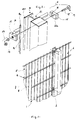
- figure 1 : une vue partielle d'une clôture selon l'invention,
- figure 2 : une vue éclatée d'un détail de la figure 1,
- figures 3 à 8 : des exemples de réalisation.
- FIG. 1: a partial view of a fence according to the invention,
- FIG. 2: an exploded view of a detail of FIG. 1,
- Figures 3 to 8: exemplary embodiments.
En se reportant au dessin, on voit que, pour matérialiser une limite prédéterminée, on a érigé à l'emplacement de cette limite une clôture 1.Referring to the drawing, we see that, to materialize a predetermined limit, we erected at the location of this limit a fence 1.
Classiquement, la clôture est constituée d'une pluralité
de poteaux 2 ancrés dans le sol et entre lesquels s'étendent
des panneaux 4.Classically, the fence consists of a plurality
of
Ces panneaux 4 sont constitués par deux nappes 5, 6 de
fils 7, 8 dont les fils 7 d'une nappe sont sensiblement
perpendiculaires à ceux 8 de l'autre nappe 6, ces fils étant
soudés à leur intersection pour constituer un treillis 4 qui
est sensiblement rigide.These
Chaque panneau 4 peut présenter en outre des nervures (non
représentées) qui augmentent la rigidité globale de ce panneau
et, par exemple, ces nervures sont obtenues par déformation
locale des fils 7, 8 longitudinaux et/ou transversaux.Each
Chaque poteau 2 comprend un moyen 10 dit de positionnement
pour une fraction déterminée d'un panneau 4 et des moyens 11 de
fixation du panneau 4 ainsi positionné.Each
Le moyen de positionnement consite en au moins une
feuillure 10 dans laquelle vient se loger l'une 12 des
extrémités 12, 13 d'un panneau 4 dont la longueur est
sensiblement égale à la distance séparant les fonds des deux
feuillures en vis à vis portées par deux poteaux successifs.The positioning means consists of at least one
Classiquement, pour le montage de la clôture, après avoir disposé des poteaux au long d'un tracé prédéterminé, on assemble chaque panneau avec chaque poteau.Conventionally, for mounting the fence, after having placed posts along a predetermined route, we assemble each panel with each post.
Pour le montage des panneaux sur les poteaux :
- on introduit l'extrémité de chaque panneau dans la
feuillure 10 correspondante, - on positionne le
panneau 4 dans lafeuillure 10, - on bride le fil extrême 8a du panneau sur le fond de la feuillure à l'aide d'une bride épaisse 15 verrouillée dans la feuillure par un organe traversant le fond de cette feuillure et prenant appui au moins indirectement sur la face opposée au fond de ladite feuillure logeant la bride épaisse précitée.
- the end of each panel is introduced into the
corresponding rebate 10, - the
panel 4 is positioned in therebate 10, - the
end wire 8a of the panel is clamped to the bottom of the rebate using athick flange 15 locked in the rebate by a member passing through the bottom of this rebate and bearing at least indirectly on the face opposite the bottom of said rebate housing the aforementioned thick flange.
Selon l'invention, le fond 21 de la feuillure 10 présente
une pluralité de perçages 14 qui, espacés selon un pas
prédéterminé, s'étendent au long d'au moins une génératrice et
chaque moyen de fixation 11 comprend une bride 15 épaisse,
laquelle bride présente dans son épaisseur au moins une gorge
16 apte à loger l'un des dits fils verticaux 8 du panneau 4 et
un perçage 17 au travers duquel passe la tige 18 d'un moyen de
verrouillage 19 prenant au moins indirectement appui sur la
face 20 opposée au fond 21 de la feuillure 10.According to the invention, the
Selon une forme préférée de l'invention, l'épaisseur de la
bride 15 est de manière caractéristique au moins égale à trois
fois le diamètre du fil destiné à être placé dans la gorge 16.According to a preferred form of the invention, the thickness of the
L'utilisation d'une bride épaisse donne une rigidité suffisante à cette bride et évite que, par traction, celle-ci se déroule et provoque le désaccouplement du panneau avec le poteau.The use of a thick flange gives rigidity sufficient for this flange and prevents it from pulling it takes place and uncouples the panel from the post.
Avantageusement, le moyen de verrouillage 19 est de type indémontable.Advantageously, the locking means 19 is of the type cannot be dismantled.
Par exemple, il s'agit d'un boulon 19 dont l'écrou 23 est
autocassant.For example, it is a bolt 19 whose
Avantageusement, la bride présente au moins deux gorges
16, 16a. Advantageously, the flange has at least two
La gorge a une dimension tranversale légèrement supérieure au diamètre d'un fil ce qui permet le calage latérale du fil.The throat has a slightly larger transverse dimension the diameter of a wire which allows the lateral setting of the wire.
Pour des raisons d'emplacement, lorsque l'une des parois
24, 25 latérales d'une gorge n'est pas matérialisée sur la
bride 15, c'est l'une des ailes latérales 28, 29 de la
feuillure qui procure le calage latéral manquant.For reasons of location, when one of the
Avantageusement, la feuillure 10 est portée par un montant
26 assurant la rigidité du poteau.Advantageously, the
Ce montant est, par exemple, un tube à section polygonale dont une des faces forme une des ailes de la feuillure.This amount is, for example, a tube with polygonal section one of the faces of which forms one of the wings of the rebate.
Selon une caractéristique de l'invention, les deux gorges
16, 16a sont placées de manière asymétrique par rapport à un
plan médian P de la bride sensiblement parallèle à l'axe
longitudinal de la tige 18 de manière, par réversibilité de la
bride, à offrir quatre possibilités de positionnement du fil
extrême d'un panneau.According to a characteristic of the invention, the two
Cette particularité technique permet le montage d'une pluralité de type de panneaux (figures 3 à 8.This technical feature allows the mounting of a multiple types of panels (Figures 3 to 8.
De manière remarquable, la feuillure 10 est portée par la
face avant ou la face arrière d'un montant 26, les faces avant
et arrière étant définies pour un observateur placé à
l'extérieur d'une enceinte délimitée par la clôture.Remarkably, the
Claims (10)
- A method of assembling a fence, the fence being constituted by a plurality of posts (2) arranged along a pre-determined line and anchored in the earth, and between which extend panels (4) that are joined to the posts,the panels (4) consisting of two layers (5, 6) of wires (7, 8) in which the wires of one layer are substantially perpendicular to the wires (8) of the other layer (6), the wires being welded at their points of intersection to create a substantially rigid lattice (4), each post (2) comprising a means (10), being called a positioning means, for a given fraction of a panel (4) and means (11) for fixing the thus-positioned panel (4),the positioning means consisting of at least one rebate (10) in which is housed one (12) of the ends (12, 13) of a panel (4), the length of which is substantially equal to the distance separating the bottoms of two opposing rebates provided on two successive posts,according to which method:the end of each panel is introduced into the corresponding rebate (10),the panel (4) is positioned in the rebate (10) andthe panel is locked in the rebate,the method being characterised in that the end wire (8a) of the panel is flange-mounted on the bottom of the rebate using a thick flange (15) which is locked in the rebate by a locking means (19) passing through the bottom of the rebate and being supported, at least indirectly, on the face opposite the bottom of the rebate housing the aforementioned thick flange.
- Means for implementing the method of assembling a fence according to claim 1, the fence being constituted by a plurality of posts (2) which are anchored in the earth and between which extend panels (4) consisting of two layers (5, 6) of wires (7, 8) in which the wires of one layer are substantially perpendicular to the wires (8) of the other layer (6), the wires being welded at their points of intersection to create a substantially rigid lattice (4),each post (2) comprising a means (10), being called a positioning means, for a given fraction of a panel (4) and means (11) for fixing the thus-positioned panel (4),the positioning means consisting of at least one rebate (10) in which is housed one (12) of the ends (12, 13) of a panel (4), the length of which is substantially equal to the distance separating the bottoms of two opposing rebates provided on two successive posts,these means being characterised in that the bottom (21) of the rebate (10) has a plurality of drilled holes (14) which are spaced at pre-determined intervals and extend along at least one generating line, and each fixing means (11) comprises a thick flange (15) having, in its thickness, at least one channel (16) capable of housing one of the vertical wires (8) of the panel (4) and a drilled hole (17) through which passes the rod (18) of a locking means (19) being at least indirectly supported on the face (20) opposite the bottom (21) of the rebate (10) housing the aforementioned thick flange.
- Means according to claim 2, characterised in that the thickness of the flange (15) is at least equal to three times the diameter of the wire intended to be placed in the channel (16).
- Means according to claim 2, characterised in that the locking means (19) is of the non-removable type.
- Means according to claim 4, characterised in that the locking means (19) is a bolt (19), the nut (23) of which is self-locking.
- Means according to claim 2, characterised in that the flange has at least two channels (16, 16a).
- Means according to claim 6, characterised in that the two channels (16, 16a) are placed asymmetrically in relation to a median plane (P) of the flange, which is substantially parallel to the longitudinal axis of the rod (18), such that, on account of the reversibility of the flange, the channels (16, 16a) offer four options for positioning the end wire of a panel.
- Means according to claim 2, characterised in that the rebate (10) is provided on the front face of an upright member (26).
- Means according to claim 2, characterised in that the rebate (10) is provided on the rear face of an upright member (26).
- A fence provided with means according to any one of claims 2 to 9.
Applications Claiming Priority (2)
| Application Number | Priority Date | Filing Date | Title |
|---|---|---|---|
| FR9213496A FR2697565B1 (en) | 1992-11-02 | 1992-11-02 | Method of mounting a fence, means for its implementation and fences thus obtained. |
| FR9213496 | 1992-11-02 |
Publications (2)
| Publication Number | Publication Date |
|---|---|
| EP0596825A1 EP0596825A1 (en) | 1994-05-11 |
| EP0596825B1 true EP0596825B1 (en) | 1999-03-17 |
Family
ID=9435382
Family Applications (1)
| Application Number | Title | Priority Date | Filing Date |
|---|---|---|---|
| EP93490018A Expired - Lifetime EP0596825B1 (en) | 1992-11-02 | 1993-10-06 | Process for assembling a fence, means needed to realize this process and the fence obtained |
Country Status (3)
| Country | Link |
|---|---|
| EP (1) | EP0596825B1 (en) |
| DE (1) | DE69323953T2 (en) |
| FR (1) | FR2697565B1 (en) |
Families Citing this family (10)
| Publication number | Priority date | Publication date | Assignee | Title |
|---|---|---|---|---|
| BE1011725A3 (en) | 1998-02-04 | 1999-12-07 | Bekaert Sa Nv | UNIVERSAL T-SHAPED POST ENTRY CLAMP BODIES FOR SUBSEQUENT ATTACHING PANELS welded mesh. |
| FR2800116B1 (en) * | 1999-10-25 | 2001-12-21 | Michel Willoquaux | DEVICE FOR FIXING A MESH PANEL ON A POST AND WALL PROVIDED WITH FIXING DEVICE |
| FR2831584B1 (en) | 2001-10-29 | 2004-02-27 | Clotures Michel Willoquaux | FENCE POST |
| FR2831583B1 (en) * | 2001-10-31 | 2004-03-12 | Rene Bosmy Soc Normande De Clo | FENCE COMPRISING A PLURALITY OF POSTS AND LATTICE PANELS AND METHOD FOR LAYING SUCH A FENCE |
| GB0615811D0 (en) * | 2006-08-09 | 2006-09-20 | Froud Robert T J | Tennis Practice Structure |
| FR2914937B1 (en) * | 2007-04-11 | 2009-05-29 | Clotures Michel Willoquaux Sa | CLAMP |
| EP2439360B1 (en) * | 2010-10-06 | 2014-11-26 | KMS Systeme GmbH & Co. KG | Device for securing at least one fence panel to a fence post |
| GB2576257B (en) | 2018-02-09 | 2020-09-16 | Bja Trading Ltd | Improvements in and relating to fencing |
| FR3084899B1 (en) * | 2018-08-13 | 2024-04-12 | Sarl Clotures Et Portails De France | ACCESSORY FOR FIXING A GRIDING PANEL TO A FENCE POST COMPRISING A LOCKING PIECE AND A CLAMPING PIECE |
| FR3093122B1 (en) | 2019-02-25 | 2022-04-22 | Eurofence | Fence installation kit |
Family Cites Families (6)
| Publication number | Priority date | Publication date | Assignee | Title |
|---|---|---|---|---|
| DE2647576C3 (en) * | 1976-10-21 | 1979-04-05 | Hermann 5802 Wetter Aderhold | Fence mesh |
| FR2482221A1 (en) * | 1980-05-08 | 1981-11-13 | Orsogril Spa | Anti-theft grille securing bolt - has nut with polygonal portion joined to body via weakened neck |
| FR2638776B1 (en) * | 1988-11-09 | 1991-08-02 | Gantois Ets | IMPROVEMENT IN FENCE WITH WELDED MESH |
| DE4005160A1 (en) | 1990-02-17 | 1991-08-22 | Aderhold Hermann Adronit Werk | Lattice fence |
| FR2667103B1 (en) * | 1990-09-26 | 1996-11-29 | Const Prefabriquees Mont | IMPROVEMENT ON POSTS FOR FENCING. |
| GB9023557D0 (en) * | 1990-10-30 | 1990-12-12 | Tinsley Wire Ltd | Mesh fencing panel securing means |
-
1992
- 1992-11-02 FR FR9213496A patent/FR2697565B1/en not_active Expired - Lifetime
-
1993
- 1993-10-06 DE DE69323953T patent/DE69323953T2/en not_active Expired - Lifetime
- 1993-10-06 EP EP93490018A patent/EP0596825B1/en not_active Expired - Lifetime
Also Published As
| Publication number | Publication date |
|---|---|
| FR2697565B1 (en) | 1995-01-06 |
| DE69323953T2 (en) | 1999-11-18 |
| DE69323953D1 (en) | 1999-04-22 |
| EP0596825A1 (en) | 1994-05-11 |
| FR2697565A1 (en) | 1994-05-06 |
Similar Documents
| Publication | Publication Date | Title |
|---|---|---|
| EP0596825B1 (en) | Process for assembling a fence, means needed to realize this process and the fence obtained | |
| EP0368778B1 (en) | Welded wire fence | |
| EP1444402A1 (en) | Channel element for road drainage gutter | |
| EP0170597B1 (en) | Cornice for bridges | |
| EP0586320A1 (en) | System for the connection of a stiffening element of a curtain wall to a construction element | |
| EP1607551B1 (en) | Fixation element for a wire fence to a post, and fence implementing such elements | |
| FR2901826A1 (en) | Fence panel`s vertical end wire maintenance clip, has fins defining V shape whose opening is elastically deformable so that fins` free ends cooperate with stops of lateral fins of grooves for temporarily anchoring clip in stops | |
| EP0141750B1 (en) | Modular fence with sections comprising at least one horizontal rail between two round posts | |
| FR2838469A1 (en) | Fence accessory for hanging trellis panels consists of body with longitudinal size equal to fence post rabbet width, support face on rabbet bottom and stop zone turned towards bottom of hooks | |
| EP1308584B1 (en) | Fence with a multitude of posts and wired panels and method of erecting the same | |
| FR2701519A1 (en) | Device for assembling tubular elements | |
| FR2833630A1 (en) | Wooden crash barrier comprises log with square mortise receiving rigidifying support element which receives connecting sleeve at each end engaging element of another log | |
| EP3006650A1 (en) | Screen device for making a fence and fence without posts made using such a device | |
| FR2517722A1 (en) | Clip for installing false ceiling panel - incorporates projection on vertical tongue which engages slot in support structure | |
| FR2574697A2 (en) | Anchoring device | |
| FR2713266A1 (en) | Fixings device for fabricating fencing | |
| FR2790520A1 (en) | Fixings for attaching grid on road gutter comprises clip and component deforming clip by compression followed by going back to original shape to ensure assembly | |
| EP2666934B1 (en) | Method of raising an existing fence, raising post and fence post raised in such a way | |
| EP1908897B1 (en) | Fence assembly | |
| FR2709528A1 (en) | Device for supporting cables or conduits. | |
| FR2885146A1 (en) | Panel fixation device for e.g. road construction, has arms with ends respectively fixed to support side bearing plate and panel side panel support, and unit to adjust length of one arm to adjust inclination of panel with respect to support | |
| FR2737524A1 (en) | Fencing support post - comprises vertical upright positioned between separate concrete blocks and clamped by two flanges which are fixed by tie rod placed transversely in gap separating blocks | |
| FR2791378A1 (en) | Frame for outdoor fence has horizontal rails fixed along panels and connected by sleeves with self tapping screws | |
| FR2688536A1 (en) | Tubular post | |
| FR2684144A1 (en) | Linear element and construction method by assembling such elements |
Legal Events
| Date | Code | Title | Description |
|---|---|---|---|
| PUAI | Public reference made under article 153(3) epc to a published international application that has entered the european phase |
Free format text: ORIGINAL CODE: 0009012 |
|
| AK | Designated contracting states |
Kind code of ref document: A1 Designated state(s): BE CH DE ES IT LI LU NL |
|
| 17P | Request for examination filed |
Effective date: 19940517 |
|
| 17Q | First examination report despatched |
Effective date: 19960423 |
|
| GRAG | Despatch of communication of intention to grant |
Free format text: ORIGINAL CODE: EPIDOS AGRA |
|
| GRAG | Despatch of communication of intention to grant |
Free format text: ORIGINAL CODE: EPIDOS AGRA |
|
| GRAH | Despatch of communication of intention to grant a patent |
Free format text: ORIGINAL CODE: EPIDOS IGRA |
|
| GRAH | Despatch of communication of intention to grant a patent |
Free format text: ORIGINAL CODE: EPIDOS IGRA |
|
| GRAA | (expected) grant |
Free format text: ORIGINAL CODE: 0009210 |
|
| AK | Designated contracting states |
Kind code of ref document: B1 Designated state(s): BE CH DE ES IT LI LU NL |
|
| PG25 | Lapsed in a contracting state [announced via postgrant information from national office to epo] |
Ref country code: NL Free format text: LAPSE BECAUSE OF FAILURE TO SUBMIT A TRANSLATION OF THE DESCRIPTION OR TO PAY THE FEE WITHIN THE PRESCRIBED TIME-LIMIT Effective date: 19990317 Ref country code: IT Free format text: LAPSE BECAUSE OF FAILURE TO SUBMIT A TRANSLATION OF THE DESCRIPTION OR TO PAY THE FEE WITHIN THE PRE;WARNING: LAPSES OF ITALIAN PATENTS WITH EFFECTIVE DATE BEFORE 2007 MAY HAVE OCCURRED AT ANY TIME BEFORE 2007. THE CORRECT EFFECTIVE DATE MAY BE DIFFERENT FROM THE ONE RECORDED.SCRIBED TIME-LIMIT Effective date: 19990317 Ref country code: ES Free format text: THE PATENT HAS BEEN ANNULLED BY A DECISION OF A NATIONAL AUTHORITY Effective date: 19990317 |
|
| REG | Reference to a national code |
Ref country code: CH Ref legal event code: EP |
|
| REF | Corresponds to: |
Ref document number: 69323953 Country of ref document: DE Date of ref document: 19990422 |
|
| NLV1 | Nl: lapsed or annulled due to failure to fulfill the requirements of art. 29p and 29m of the patents act | ||
| PG25 | Lapsed in a contracting state [announced via postgrant information from national office to epo] |
Ref country code: LI Free format text: LAPSE BECAUSE OF NON-PAYMENT OF DUE FEES Effective date: 19991031 Ref country code: CH Free format text: LAPSE BECAUSE OF NON-PAYMENT OF DUE FEES Effective date: 19991031 |
|
| PLBE | No opposition filed within time limit |
Free format text: ORIGINAL CODE: 0009261 |
|
| STAA | Information on the status of an ep patent application or granted ep patent |
Free format text: STATUS: NO OPPOSITION FILED WITHIN TIME LIMIT |
|
| 26N | No opposition filed | ||
| REG | Reference to a national code |
Ref country code: CH Ref legal event code: PL |
|
| PGFP | Annual fee paid to national office [announced via postgrant information from national office to epo] |
Ref country code: LU Payment date: 20121031 Year of fee payment: 20 |
|
| PGFP | Annual fee paid to national office [announced via postgrant information from national office to epo] |
Ref country code: BE Payment date: 20121025 Year of fee payment: 20 Ref country code: DE Payment date: 20121029 Year of fee payment: 20 |
|
| REG | Reference to a national code |
Ref country code: DE Ref legal event code: R071 Ref document number: 69323953 Country of ref document: DE |
|
| BE20 | Be: patent expired |
Owner name: *WILLOQUAUX MICHEL Effective date: 20131006 |
|
| PG25 | Lapsed in a contracting state [announced via postgrant information from national office to epo] |
Ref country code: DE Free format text: LAPSE BECAUSE OF EXPIRATION OF PROTECTION Effective date: 20131008 |