EP1864764A2 - Appareil de simulation robot - Google Patents
Appareil de simulation robot Download PDFInfo
- Publication number
- EP1864764A2 EP1864764A2 EP07010714A EP07010714A EP1864764A2 EP 1864764 A2 EP1864764 A2 EP 1864764A2 EP 07010714 A EP07010714 A EP 07010714A EP 07010714 A EP07010714 A EP 07010714A EP 1864764 A2 EP1864764 A2 EP 1864764A2
- Authority
- EP
- European Patent Office
- Prior art keywords
- workpiece
- robot
- workpieces
- model
- virtual space
- Prior art date
- Legal status (The legal status is an assumption and is not a legal conclusion. Google has not performed a legal analysis and makes no representation as to the accuracy of the status listed.)
- Granted
Links
Images


Classifications
-
- B—PERFORMING OPERATIONS; TRANSPORTING
- B25—HAND TOOLS; PORTABLE POWER-DRIVEN TOOLS; MANIPULATORS
- B25J—MANIPULATORS; CHAMBERS PROVIDED WITH MANIPULATION DEVICES
- B25J9/00—Programme-controlled manipulators
- B25J9/16—Programme controls
- B25J9/1656—Programme controls characterised by programming, planning systems for manipulators
- B25J9/1671—Programme controls characterised by programming, planning systems for manipulators characterised by simulation, either to verify existing program or to create and verify new program, CAD/CAM oriented, graphic oriented programming systems
-
- G—PHYSICS
- G05—CONTROLLING; REGULATING
- G05B—CONTROL OR REGULATING SYSTEMS IN GENERAL; FUNCTIONAL ELEMENTS OF SUCH SYSTEMS; MONITORING OR TESTING ARRANGEMENTS FOR SUCH SYSTEMS OR ELEMENTS
- G05B19/00—Programme-control systems
- G05B19/02—Programme-control systems electric
- G05B19/18—Numerical control [NC], i.e. automatically operating machines, in particular machine tools, e.g. in a manufacturing environment, so as to execute positioning, movement or co-ordinated operations by means of programme data in numerical form
- G05B19/406—Numerical control [NC], i.e. automatically operating machines, in particular machine tools, e.g. in a manufacturing environment, so as to execute positioning, movement or co-ordinated operations by means of programme data in numerical form characterised by monitoring or safety
- G05B19/4069—Simulating machining process on screen
-
- G—PHYSICS
- G05—CONTROLLING; REGULATING
- G05B—CONTROL OR REGULATING SYSTEMS IN GENERAL; FUNCTIONAL ELEMENTS OF SUCH SYSTEMS; MONITORING OR TESTING ARRANGEMENTS FOR SUCH SYSTEMS OR ELEMENTS
- G05B2219/00—Program-control systems
- G05B2219/30—Nc systems
- G05B2219/32—Operator till task planning
- G05B2219/32351—Visual, graphical animation of process
-
- G—PHYSICS
- G05—CONTROLLING; REGULATING
- G05B—CONTROL OR REGULATING SYSTEMS IN GENERAL; FUNCTIONAL ELEMENTS OF SUCH SYSTEMS; MONITORING OR TESTING ARRANGEMENTS FOR SUCH SYSTEMS OR ELEMENTS
- G05B2219/00—Program-control systems
- G05B2219/30—Nc systems
- G05B2219/39—Robotics, robotics to robotics hand
- G05B2219/39031—Use of model for robot and for measuring device
-
- G—PHYSICS
- G05—CONTROLLING; REGULATING
- G05B—CONTROL OR REGULATING SYSTEMS IN GENERAL; FUNCTIONAL ELEMENTS OF SUCH SYSTEMS; MONITORING OR TESTING ARRANGEMENTS FOR SUCH SYSTEMS OR ELEMENTS
- G05B2219/00—Program-control systems
- G05B2219/30—Nc systems
- G05B2219/40—Robotics, robotics mapping to robotics vision
- G05B2219/40003—Move end effector so that image center is shifted to desired position
-
- G—PHYSICS
- G05—CONTROLLING; REGULATING
- G05B—CONTROL OR REGULATING SYSTEMS IN GENERAL; FUNCTIONAL ELEMENTS OF SUCH SYSTEMS; MONITORING OR TESTING ARRANGEMENTS FOR SUCH SYSTEMS OR ELEMENTS
- G05B2219/00—Program-control systems
- G05B2219/30—Nc systems
- G05B2219/40—Robotics, robotics mapping to robotics vision
- G05B2219/40121—Trajectory planning in virtual space
-
- G—PHYSICS
- G05—CONTROLLING; REGULATING
- G05B—CONTROL OR REGULATING SYSTEMS IN GENERAL; FUNCTIONAL ELEMENTS OF SUCH SYSTEMS; MONITORING OR TESTING ARRANGEMENTS FOR SUCH SYSTEMS OR ELEMENTS
- G05B2219/00—Program-control systems
- G05B2219/30—Nc systems
- G05B2219/40—Robotics, robotics mapping to robotics vision
- G05B2219/40122—Manipulate virtual object, for trajectory planning of real object, haptic display
-
- G—PHYSICS
- G05—CONTROLLING; REGULATING
- G05B—CONTROL OR REGULATING SYSTEMS IN GENERAL; FUNCTIONAL ELEMENTS OF SUCH SYSTEMS; MONITORING OR TESTING ARRANGEMENTS FOR SUCH SYSTEMS OR ELEMENTS
- G05B2219/00—Program-control systems
- G05B2219/30—Nc systems
- G05B2219/40—Robotics, robotics mapping to robotics vision
- G05B2219/40127—Virtual tape measure, indicate distance between end effector and destination
-
- G—PHYSICS
- G05—CONTROLLING; REGULATING
- G05B—CONTROL OR REGULATING SYSTEMS IN GENERAL; FUNCTIONAL ELEMENTS OF SUCH SYSTEMS; MONITORING OR TESTING ARRANGEMENTS FOR SUCH SYSTEMS OR ELEMENTS
- G05B2219/00—Program-control systems
- G05B2219/30—Nc systems
- G05B2219/40—Robotics, robotics mapping to robotics vision
- G05B2219/40131—Virtual reality control, programming of manipulator
-
- G—PHYSICS
- G05—CONTROLLING; REGULATING
- G05B—CONTROL OR REGULATING SYSTEMS IN GENERAL; FUNCTIONAL ELEMENTS OF SUCH SYSTEMS; MONITORING OR TESTING ARRANGEMENTS FOR SUCH SYSTEMS OR ELEMENTS
- G05B2219/00—Program-control systems
- G05B2219/30—Nc systems
- G05B2219/40—Robotics, robotics mapping to robotics vision
- G05B2219/40314—Simulation of program locally before remote operation
-
- Y—GENERAL TAGGING OF NEW TECHNOLOGICAL DEVELOPMENTS; GENERAL TAGGING OF CROSS-SECTIONAL TECHNOLOGIES SPANNING OVER SEVERAL SECTIONS OF THE IPC; TECHNICAL SUBJECTS COVERED BY FORMER USPC CROSS-REFERENCE ART COLLECTIONS [XRACs] AND DIGESTS
- Y02—TECHNOLOGIES OR APPLICATIONS FOR MITIGATION OR ADAPTATION AGAINST CLIMATE CHANGE
- Y02P—CLIMATE CHANGE MITIGATION TECHNOLOGIES IN THE PRODUCTION OR PROCESSING OF GOODS
- Y02P90/00—Enabling technologies with a potential contribution to greenhouse gas [GHG] emissions mitigation
- Y02P90/02—Total factory control, e.g. smart factories, flexible manufacturing systems [FMS] or integrated manufacturing systems [IMS]
Definitions
- This invention relates to a simulation apparatus for a robot system including an imaging means and a robot.
- a simulation apparatus is known wherein three-dimensional models such as a robot, workpiece and peripheral devices, etc. are arranged and displayed on the screen of a computer, and based on designated robot move commands, etc., the robot motion is simulated.
- This simulation apparatus is used for creating a robot motion program off line, and evaluating, correcting or editing the program created off line.
- the conventional simulation apparatus cannot substantially perform a simulation relating to the imaging means in the case of creating off line, correcting or editing a program.
- Japanese Unexamined Patent Publication No. 2005-135278 discloses a simulation apparatus in which an imaging means is arranged on a three-dimensional model and the visual field of the imaging means is displayed on the three-dimensional model, and as a result, can perform the simulation relating to an imaging means.
- a robot picks up a plurality of workpieces having the same shape stacked in bulk in a container.
- the plurality of workpieces are arranged irregularly three-dimensionally.
- the robot hand may interfere with workpieces other than a workpiece to be picked up or the container's wall.
- the simulation apparatus disclosed in Japanese Unexamined Patent Publication No. 2005-135278 does not presuppose the picking up of workpieces in bulk, and therefore, interference between the robot hand and workpieces or the container cannot be predicted.
- This invention has been achieved in view of this situation, and the object thereof is to provide a simulation apparatus wherein the time required to pick up all of the workpieces from a container accommodating the workpieces stacked in bulk therein, is accurately determined while predicting interference between the robot and workpieces and between the robot and the container.
- a robot simulation apparatus capable of creating and executing a robot program, comprising a virtual space creating means for creating a virtual space for three-dimensionally expressing the working space in which the robot carries out the handling operation of workpieces, a workpiece model layout means for automatically arranging one or a plurality of models of the workpieces in an appropriate posture at appropriate positions in a workpiece layout area model defined in the virtual space created by the virtual space creating means or a workpiece accommodation means model arranged in the virtual space, a virtual camera means for acquiring a virtual image of the workpiece models existing in the range of a designated visual field designated as viewed from a designated place in the virtual space, a correcting means for correcting the teaching points of the robot program based on the virtual image acquired by the virtual camera means, and a simulation means for simulating the robot operation of handling the workpieces based on the program in which the teaching points are corrected by the correcting means.
- a plurality of workpiece models are arranged in appropriate postures at appropriate positions, and therefore, the workpieces stacked in bulk in the container can be expressed on a virtual space.
- interference between the robot and the workpieces and between the robot and the container can be predicted, thereby making it possible to accurately determine the time required to pick up all of the workpieces.
- a robot simulation apparatus in the first aspect, wherein the workpiece model layout means arranges a designated number of the workpiece models in the virtual space.
- interference and required time can be more accurately predicted based on the number of the workpiece models arranged in the container model.
- a robot simulation apparatus in the first or second aspect, wherein the workpiece model layout means arranges a plurality of the workpiece models in such a manner that the workpiece models does not share the same space.
- the more accurate simulation is made possible by making sure that a plurality of workpiece models do not overlap one another in the three-dimensional virtual space.
- a robot simulation apparatus in any one of the first to third aspects, further comprising a workpiece attribute information storage means for storing workpiece attribute information, wherein the workpiece model layout means calculates the distortion amount of each workpiece based on the workpiece attribute information stored in the workpiece attribute information storage means and the information of the contact portions of a plurality of the workpieces, and arranges the workpiece models in a deformed state based on the distortion amount.
- the workpiece attribute information includes the stiffness, weight and center of gravity of the workpieces.
- the distortion amount of the workpieces stacked in bulk is taken into account, and therefore, a more accurate simulation is possible.
- a robot simulation apparatus in any one of the first to fifth aspects, further comprising a robot motion storage means for monitoring and storing the actual motion of the robot, wherein the workpiece model layout means, based on the actual motion of the robot stored in the robot motion storage means, calculates the position and posture of the robot hand at the time of grasping each of the plurality of the workpieces and arranges the workpiece models based on the hand position and posture thus calculated.
- the handling operation for picking up a plurality of workpieces stacked in bulk in the container by the robot can be reproduced in a virtual space.
- Fig. 1 is a diagram showing a general layout of a robot simulation system according to the invention.
- a robot simulation apparatus 10 shown in Fig. 1 is a digital computer, for example, and can create and execute a robot program.
- the robot simulation apparatus 10 is connected to a robot controller 29 via a LAN 29, such as an Ethernet (registered trade mark) and may alternatively be connected by another method.
- a LAN 29 such as an Ethernet (registered trade mark) and may alternatively be connected by another method.
- a cage-like container 24 is arranged at a predetermined position. As shown, a plurality of workpieces 20 having the same shape are placed in bulk in the container 24.
- the container 24 has an outer wall 25 whereby an opening 26 is defined.
- the opening 26, though rectangular in Fig. 1, may have another shape. Also, each of the plurality of the workpieces, though shown parallelepiped, may alternatively have another shape.
- the robot controller 21 is connected to a robot 22 whose arm has a hand 23 at the forward end of the arm.
- the robot controller 21 controls the robot 22 to pick up workpieces 20 sequentially from the container 24.
- An imaging means 55 such as a CCD camera is arranged at a predetermined position above the container 24.
- the imaging means 55 is positioned by a stand (not shown).
- the imaging means 55 may alternatively be mounted on a part of the robot 22.
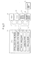
- Fig. 2 is a block diagram showing the robot simulation apparatus according to the invention.
- the robot simulation apparatus 10 includes a CPU 11, a storage unit having a ROM 12 and RAM 13, an input and output device 14 having a mouse and/or keyboard and a graphics control circuit 15, which are interconnected by a bidirectional bus 16.
- the CPU 11 functions as a virtual space creating means 31 for creating a virtual space for three-dimensionally expressing the working space in which the robot 22 carries out the handling operation of the workpieces 20, a workpiece model layout means 32 for automatically arranging workpiece models of the workpieces 20 in the model of the container 24 in the virtual space, a virtual camera means 33 for acquiring a virtual image of the workpiece models in the virtual space, a correcting means 34 for correcting the teaching points in the robot program based on the virtual image and a simulation means 35 for simulating the operation of the robot 22 to handle the workpieces 20 based on the corrected program.
- the RAM 13 of the storage unit has stored therein data on the three-dimensional geometric models for the robot 22, container 24, workpieces 20 and peripheral devices thereof intended for simulation.
- the RAM 13 also has stored therein workpiece attribute information such as the stiffness of workpieces 20, weight of the workpieces 20 and center of gravity of each workpiece 20.
- operation programs 100 to 400, described later for the robot simulation apparatus 10 and the robot program for operating the robot 22 are stored in the ROM 12 of the storage unit. Also, as shown, the graphics control circuit 15 is connected to a display unit 19, such as a liquid crystal monitor or CRT.
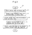
- Fig. 3 is a flowchart showing the operation program of the robot simulation apparatus according to the invention. The operation of the robot simulation apparatus 10 according to the invention is explained below with reference to the operation program shown in Fig. 3.
- a three-dimensional virtual space 60 for carrying out the simulation is created by a virtual space creating means 31 (step 101).
- the three-dimensional virtual space 60 thus created is displayed on a display unit 19 via the graphics control circuit 15.
- Fig. 4 is a diagram showing the three-dimensional virtual space displayed on the display unit 19.
- the three-dimensional virtual space 60 is displayed on a first screen 51 on the display unit 19.
- a container model 44 corresponding to the container 24 shown in Fig. 1 is displayed in the three-dimensional virtual space 60 on the first screen 51.
- This container model 44 is created based on the three-dimensional geometric data stored in the storage unit, and an outer wall 45 and an opening 46 corresponding to the outer wall 25 and the opening 26, respectively, are also displayed.
- the viewpoints of the three-dimensional virtual space 60 can be three-dimensionally changed by use of an input/output device, such as a mouse.
- the workpiece models 40 corresponding to the workpieces 20 are arranged in the three-dimensional virtual space 60 by the workpiece model layout means 32.
- the workpiece models 40 are also created based on the three-dimensional geometric data of the workpieces 20 stored in the storage unit.
- a plurality of the workpiece models 40 are automatically arranged at appropriate positions in appropriate postures in the container model 44 by the workpiece model layout means 32.
- the method of arranging the plurality of the workpiece models 40 is explained below.
- Fig. 5 is a diagram explaining the method of arranging the plurality of the workpiece models 40, and to facilitate explanation, Fig. 5 shows the models two- dimensionally.
- step 201 of the program 200 in Fig. 5 first, one workpiece model 40 is arranged in an appropriate posture at an appropriate position above the container model 44 by the workpiece model layout means 32.
- the posture and position of each workpiece model 40 is determined in the workpiece model layout means 32 using a random number or the like.
- step 202 the workpiece model 40 is moved down without changing the posture thereof, so that the workpiece model 40 reaches the bottom surface 47 of the container model 44.
- step 201 the process is returned to step 201, in which another workpiece model 40 is arranged above the container model 44 and then moved down toward the bottom surface 47.
- another workpiece model 40 is arranged in such a manner so as to not be superposed on the workpiece model 40 already arranged in the container model 44.
- another workpiece model 40 may not be in contact with the bottom surface 47 or the outer wall 45 of the container model 44.
- This process is repeated a predetermined number of times thereby to arrange a plurality of the workpiece models 40 in the container model 44 (step 203).
- each workpiece model 40 is determined at random using a random number or the like, and a plurality of the workpiece models 40 are arranged in a manner not to be superposed on one another. Therefore, the postures, etc. of the workpiece models 40 are very similar to the postures, etc. of the actual workpieces 20 stacked in bulk in the container 24. According to this invention, the operation of picking up a plurality of workpieces having the same shape stacked in bulk in the container can be simulated with higher accuracy.
- a camera model 55' is arranged at a place designated in advance in the three-dimensional virtual space 60 of the first screen 51. This place corresponds to the place of the actual imaging means 55 (Fig. 1).
- the camera model 55' is arranged just above the container model 44.
- the dashed lines extending from the camera model 55' indicate a visual field 56' of the camera model 55'.
- This visual field 56' corresponds to the visual field of the actual imaging means 55 (Fig. 1).
- the visual field 56' of the camera model 55' covers a plurality of the workpiece models 40 arranged in the container model 44.
- the camera model 55' can acquire the virtual image of the workpiece models 40 in the visual field 56' through a virtual camera means 33.
- the virtual camera means 33 displays the acquired virtual image as a second screen 52 on the display unit 19 (see step 103 in Fig. 3).
- the first screen 51 and the second screen 52 are plotted as different windows.
- the virtual image covered by the camera model 55' may be plotted at a corner of the first screen 51.
- the correcting means 34 first selects an appropriate workpiece model 40 such as a workpiece model 40a from the virtual image on the second screen 52 and calculates the posture and position thereof.
- the robot program describes the method by which the hand 23 of the robot 22 grasps a workpiece 20 in a predetermined posture at a predetermined position.
- the teaching points in the robot program are thus changed based on the calculated posture and position of the workpiece model 40a so that the hand 23 of the robot 22 can grasp the workpiece model 40a.
- the correcting means 34 sequentially selects other workpiece models 40b, 40c,.... and calculating the posture and position thereof similarly, changes the teaching points so that the hand 23 can grasp the workpiece models 40b, 40c,.... (step 104).
- the workpiece model 40d is located under the workpiece model 40a, and therefore, only a part of the workpiece model 40d is shown in the second screen 52.
- the workpiece model 40a existing on this side constitutes an obstacle, and therefore, the posture and position of the workpiece model 40d are difficult to calculate.
- the workpiece model 40a constituting an obstacle is provisionally deleted to calculate the posture and position of the workpiece model 40d at a lower position. In this way, the teaching points of the robot program are changed in such a manner that all the workpiece models 40 can be grasped.
- the robot model 22' of the robot 22 is displayed in the three-dimensional virtual space 60 on the first screen 51.
- the simulation means 35 operates the robot model 22' by simulation on the three-dimensional virtual space 60 (step 105).
- the simulation operation by the simulation means 35 may be performed on other screen from the first screen 51.
- the hand model 23' of the robot model 22' performs the operation of sequentially picking up the workpiece models 40 arranged in the container model 44.
- the hand 23 will be interrupted by the outer wall 25 of the container 24 and other workpieces other than the workpiece 20 to be grasped.
- the dimensions of the container model 44 may be changed on the three-dimensional virtual space 60, and the simulation may be repeated until the interruption is avoided, and as a result, the optimum size of the container 24 can be studied using the simulation.
- the hand model 23' of the optimum size can be studied similarly by changing the size of the hand model 23' on the three-dimensional virtual space 60.
- the teaching points of the robot program are changed for each of the workpiece models 40 corresponding to a plurality of the workpieces 20. Specifically, the posture of the hand 23 in the handling operation is successively changed in accordance with the specific workpiece 20 to be grasped. Therefore, according to this invention, the time required to pick up all of the plurality of the workpieces 20 from the container 24 can be accurately calculated in advance.
- the number of the workpiece models 40 arranged in the three-dimensional virtual space 60 can of course be easily changed by use of an input/output device 14, such as a mouse and/or keyboard. In other words, the simulation can be carried out more accurately by matching the number of the workpiece models 40 with the number of the actual workpieces 20.
- the workpiece model 40e is supported at a supporting point p on the workpiece model 40f and a supporting point q on the workpiece model 40g.
- the workpiece model 40e is distorted between the supporting points p and q, and therefore, it is preferable to display the workpiece model 40e while taking the distortion amount thereof into account.
- Fig. 6b is a diagram showing the method of displaying a workpiece model based on the distortion amount of a workpiece.
- the distance L between the supporting points p and q is calculated based on the relative positions of the workpiece models 40e, 40f, 40g.
- the maximum displacement ⁇ is calculated from Equation (1) below (step 301).
- ⁇ P ⁇ L 3 / 48 ⁇ E ⁇ I
- P is the weight of the workpiece 20
- E and I the modulus of elasticity and the geometrical moment of inertia, respectively.
- the weight P, the modulus of elasticity E and the geometrical moment of inertia I are stored in the ROM 12 of the storage unit in advance.
- the intermediate face M of the workpiece model 40e extending in parallel to the line segment connecting the supporting points p and q is set.
- the distance r to each corner of the workpiece model 40e from the intermediate surface M is determined.
- ⁇ i ri / ⁇ where p is the radius of curvature of the intermediate face.
- the workpiece model 40e is shown two- dimensionally in Figs. 6a, 6b, the actual workpiece 20 is three-dimensional.
- the four corners Q1 to Q4 located above the intermediate face M therefore, are compressed toward the center of the workpiece model 40e.
- the remaining four corners Q5 to Q8 located under the intermediate face M are extended outward away from the center.
- the distortion amount is of course similarly calculated for other workpiece models 40 and the corners thereof moved. In such a case, it is apparent that the three-dimensional virtual space 60 obtained is higher in accuracy, and therefore, a more accurate simulation is possible.
- the embodiment shown in Fig. 6 is advantageously applicable in the case where the workpieces 20 piled in the container 24 are liable to be deformed with comparative ease.
- Figs. 6a, 6b explained above assume that the workpiece model 40e is substantially horizontal. Nevertheless, it is apparent that the distortion amount can be similarly calculated and the corners of a workpiece model moved by a similar method also in the case where the particular workpiece model is inclined by other workpiece models.
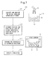
- Fig. 7 is a diagram explaining the method of reproducing the actual operation of the robot in virtual space, and is explained below with reference to Fig. 7.
- the robot 22 shown in Fig. 1 is actually operated thereby to successively pick up a plurality of workpieces 20 stacked in bulk in the container 24.
- the robot simulation apparatus 10 monitors the motion of the robot 22 at every sampling period, and stores the result of monitoring in the RAM 13 (step 401).
- the result of monitoring contains the posture and position of the hand 23 when grasping each of a plurality of the workpieces 20 and the timing of opening/closing of the hand 23.
- the black circles in Fig. 7 designate teaching points.
- step 402 based on the posture, etc. of the hand 23 thus retrieved, the posture and position of the workpieces 20 grasped by the hand 23 are estimated (step 402). This estimation is carried out for all of the workpieces 20 picked up from the container 24.
- a plurality of the workpiece models 40 are arranged in the container model 44 by the workpiece model layout means 32 based on the estimated postures, etc. of the plurality of the workpieces 20 (step 403), and as a result, the plurality of the workpieces 20 stacked in bulk in the actual container 24 can be reproduced in the three-dimensional virtual space 60.
- the robot model 22' (not shown in Fig. 7) is displayed in the three-dimensional virtual space 60, and the simulation operation of the robot model 22' is carried out using the simulation means 35 (step 404).
- the handling operation of the robot 22 for picking up the plurality of the workpieces 20 stacked in bulk in the container 24 can be reproduced.
- the cause of the error can be verified by the reproducing operation described above.
- this invention is also applicable to a case in which the plurality of the workpieces 20 are arranged in a predetermined workpiece stock area on the floor.
Applications Claiming Priority (1)
| Application Number | Priority Date | Filing Date | Title |
|---|---|---|---|
| JP2006157557A JP4238256B2 (ja) | 2006-06-06 | 2006-06-06 | ロボットシミュレーション装置 |
Publications (3)
| Publication Number | Publication Date |
|---|---|
| EP1864764A2 true EP1864764A2 (fr) | 2007-12-12 |
| EP1864764A3 EP1864764A3 (fr) | 2009-12-30 |
| EP1864764B1 EP1864764B1 (fr) | 2011-11-16 |
Family
ID=38616555
Family Applications (1)
| Application Number | Title | Priority Date | Filing Date |
|---|---|---|---|
| EP07010714A Active EP1864764B1 (fr) | 2006-06-06 | 2007-05-30 | Appareil de simulation robot |
Country Status (4)
| Country | Link |
|---|---|
| US (1) | US7881917B2 (fr) |
| EP (1) | EP1864764B1 (fr) |
| JP (1) | JP4238256B2 (fr) |
| CN (1) | CN101085523B (fr) |
Cited By (6)
| Publication number | Priority date | Publication date | Assignee | Title |
|---|---|---|---|---|
| WO2012004232A3 (fr) * | 2010-07-08 | 2012-11-15 | Abb Research Ltd. | Procédé pour étalonner un robot positionné sur une plateforme mobile |
| CN103042529A (zh) * | 2011-10-13 | 2013-04-17 | 株式会社安川电机 | 工件取出系统、机器人装置以及被加工物的制造方法 |
| WO2014121365A1 (fr) * | 2013-02-11 | 2014-08-14 | Mytnik Vyacheslav Georgievich | Procédé de commande d'un objet |
| EP2783812A3 (fr) * | 2013-03-18 | 2015-04-01 | Kabushiki Kaisha Yaskawa Denki | Dispositif de robot et procédé de fabrication d'un objet |
| EP3330813A1 (fr) * | 2016-12-02 | 2018-06-06 | Omron Corporation | Simulateur, procédé de simulation et programme de simulation |
| US10410339B2 (en) | 2015-11-18 | 2019-09-10 | Omron Corporation | Simulator, simulation method, and simulation program |
Families Citing this family (90)
| Publication number | Priority date | Publication date | Assignee | Title |
|---|---|---|---|---|
| JP2008021092A (ja) * | 2006-07-12 | 2008-01-31 | Fanuc Ltd | ロボットシステムのシミュレーション装置 |
| JP4347386B2 (ja) * | 2008-01-23 | 2009-10-21 | ファナック株式会社 | 加工用ロボットプラグラムの作成装置 |
| US8584025B2 (en) * | 2008-05-02 | 2013-11-12 | International Business Machines Corporation | Virtual world teleportation |
| JP4653836B2 (ja) * | 2008-12-12 | 2011-03-16 | ファナック株式会社 | シミュレーション装置 |
| JP5233709B2 (ja) * | 2009-02-05 | 2013-07-10 | 株式会社デンソーウェーブ | ロボットシミュレーション画像表示システム |
| KR100968944B1 (ko) * | 2009-12-14 | 2010-07-14 | (주) 아이알로봇 | 로봇 동기화 장치 및 그 방법 |
| JP4938115B2 (ja) * | 2010-07-27 | 2012-05-23 | ファナック株式会社 | ワーク取出し装置およびワーク取出し方法 |
| IT1401373B1 (it) * | 2010-08-06 | 2013-07-18 | Fidia Spa | Sistema predittivo di controllo e visualizzazione virtuale per una macchina utensile a controllo numerico |
| WO2012066819A1 (fr) * | 2010-11-17 | 2012-05-24 | 三菱電機株式会社 | Appareil de saisie de pièces |
| US9921712B2 (en) | 2010-12-29 | 2018-03-20 | Mako Surgical Corp. | System and method for providing substantially stable control of a surgical tool |
| US9119655B2 (en) | 2012-08-03 | 2015-09-01 | Stryker Corporation | Surgical manipulator capable of controlling a surgical instrument in multiple modes |
| JP5382035B2 (ja) * | 2011-03-08 | 2014-01-08 | 株式会社安川電機 | 自動作業装置 |
| JP5806606B2 (ja) | 2011-12-01 | 2015-11-10 | キヤノン株式会社 | 情報処理装置、情報処理方法 |
| JP5266377B2 (ja) * | 2011-12-19 | 2013-08-21 | ファナック株式会社 | 物品の姿勢を修正する機能を備えた取出し装置 |
| KR101896473B1 (ko) * | 2012-01-04 | 2018-10-24 | 삼성전자주식회사 | 로봇 핸드의 제어 방법 |
| JP5838873B2 (ja) * | 2012-03-15 | 2016-01-06 | オムロン株式会社 | シミュレーション装置、シミュレーション方法、および、シミュレーションプログラム |
| JP5426719B2 (ja) * | 2012-05-18 | 2014-02-26 | ファナック株式会社 | ロボットシステムの動作シミュレーション装置 |
| JP5426722B2 (ja) * | 2012-05-24 | 2014-02-26 | ファナック株式会社 | ロボットプログラム変更装置 |
| JP6157066B2 (ja) * | 2012-06-11 | 2017-07-05 | キヤノン株式会社 | 画像処理装置、物体取出システム、画像処理方法及びプログラム |
| JP5642738B2 (ja) * | 2012-07-26 | 2014-12-17 | ファナック株式会社 | バラ積みされた物品をロボットで取出す装置及び方法 |
| JP5469216B2 (ja) * | 2012-07-31 | 2014-04-16 | ファナック株式会社 | バラ積みされた物品をロボットで取出す装置 |
| KR102397265B1 (ko) | 2012-08-03 | 2022-05-12 | 스트리커 코포레이션 | 로봇 수술을 위한 시스템 및 방법 |
| US9820818B2 (en) | 2012-08-03 | 2017-11-21 | Stryker Corporation | System and method for controlling a surgical manipulator based on implant parameters |
| US9226796B2 (en) | 2012-08-03 | 2016-01-05 | Stryker Corporation | Method for detecting a disturbance as an energy applicator of a surgical instrument traverses a cutting path |
| JP5620445B2 (ja) * | 2012-09-13 | 2014-11-05 | ファナック株式会社 | 選択条件に基づいてロボットの保持位置姿勢を決定する物品取出装置 |
| JP6015282B2 (ja) * | 2012-09-21 | 2016-10-26 | オムロン株式会社 | シミュレーション装置、シミュレーション方法、およびシミュレーションプログラム |
| JP5561384B2 (ja) * | 2013-01-15 | 2014-07-30 | 株式会社安川電機 | 認識プログラム評価装置および認識プログラム評価方法 |
| JP5727528B2 (ja) * | 2013-01-30 | 2015-06-03 | ファナック株式会社 | ロボットプログラムによりシミュレーションを行うシミュレーション装置 |
| CN103085072B (zh) * | 2013-03-11 | 2014-10-29 | 南京埃斯顿机器人工程有限公司 | 基于三维建模软件实现工业机器人离线编程的方法 |
| US9102055B1 (en) * | 2013-03-15 | 2015-08-11 | Industrial Perception, Inc. | Detection and reconstruction of an environment to facilitate robotic interaction with the environment |
| JP5765355B2 (ja) * | 2013-03-18 | 2015-08-19 | 株式会社安川電機 | ロボットピッキングシステム及び被加工物の製造方法 |
| JP5975010B2 (ja) * | 2013-10-17 | 2016-08-23 | 株式会社安川電機 | ティーチングシステムおよびティーチング方法 |
| US9782896B2 (en) * | 2013-11-28 | 2017-10-10 | Mitsubishi Electric Corporation | Robot system and control method for robot system |
| CN103692441B (zh) * | 2013-12-19 | 2015-09-09 | 成都市卓睿科技有限公司 | 通过工作流技术模拟机械臂运动的系统及方法 |
| US10078712B2 (en) * | 2014-01-14 | 2018-09-18 | Energid Technologies Corporation | Digital proxy simulation of robotic hardware |
| JP5850958B2 (ja) * | 2014-01-24 | 2016-02-03 | ファナック株式会社 | ワークを撮像するためのロボットプログラムを作成するロボットプログラミング装置 |
| JP5824173B1 (ja) * | 2014-02-28 | 2015-11-25 | ファナック株式会社 | ロボットを用いて物品を整列させる物品整列装置及び物品整列方法、並びに物品整列装置を備えた物品移送システム |
| JP5877857B2 (ja) * | 2014-03-10 | 2016-03-08 | ファナック株式会社 | ワークの取出工程をシミュレーションするロボットシミュレーション装置 |
| JP5897624B2 (ja) | 2014-03-12 | 2016-03-30 | ファナック株式会社 | ワークの取出工程をシミュレーションするロボットシミュレーション装置 |
| JP5877867B2 (ja) | 2014-04-25 | 2016-03-08 | ファナック株式会社 | 複数台のロボットのシミュレーション装置 |
| JP5778311B1 (ja) * | 2014-05-08 | 2015-09-16 | 東芝機械株式会社 | ピッキング装置およびピッキング方法 |
| JP5829306B2 (ja) | 2014-05-12 | 2015-12-09 | ファナック株式会社 | レンジセンサの配置位置評価装置 |
| US9737990B2 (en) | 2014-05-16 | 2017-08-22 | Microsoft Technology Licensing, Llc | Program synthesis for robotic tasks |
| CN104057459B (zh) * | 2014-06-25 | 2017-02-22 | 上海发那科机器人有限公司 | 一种机器人智能分拣工件的装置及方法 |
| US9283678B2 (en) * | 2014-07-16 | 2016-03-15 | Google Inc. | Virtual safety cages for robotic devices |
| JP5980873B2 (ja) * | 2014-10-17 | 2016-08-31 | ファナック株式会社 | ロボットの干渉領域設定装置 |
| JP6461712B2 (ja) * | 2015-05-28 | 2019-01-30 | 株式会社東芝 | 荷役装置及びその動作方法 |
| JP6240689B2 (ja) | 2015-07-31 | 2017-11-29 | ファナック株式会社 | 人の行動パターンを学習する機械学習装置、ロボット制御装置、ロボットシステム、および機械学習方法 |
| DE102016009030B4 (de) | 2015-07-31 | 2019-05-09 | Fanuc Corporation | Vorrichtung für maschinelles Lernen, Robotersystem und maschinelles Lernsystem zum Lernen eines Werkstückaufnahmevorgangs |
| JP6522488B2 (ja) * | 2015-07-31 | 2019-05-29 | ファナック株式会社 | ワークの取り出し動作を学習する機械学習装置、ロボットシステムおよび機械学習方法 |
| JP6052372B2 (ja) * | 2015-11-12 | 2016-12-27 | オムロン株式会社 | シミュレーション装置、シミュレーション方法、および、シミュレーションプログラム |
| JP6458713B2 (ja) * | 2015-11-18 | 2019-01-30 | オムロン株式会社 | シミュレーション装置、シミュレーション方法、およびシミュレーションプログラム |
| US9669543B1 (en) | 2015-12-11 | 2017-06-06 | Amazon Technologies, Inc. | Validation of robotic item grasping |
| CN105563487B (zh) * | 2016-02-17 | 2018-08-21 | 太仓中科信息技术研究院 | 基于Maya的摄像机器人离线编程方法 |
| JP6392817B2 (ja) * | 2016-08-04 | 2018-09-19 | ファナック株式会社 | シミュレーション装置 |
| JP6514156B2 (ja) * | 2016-08-17 | 2019-05-15 | ファナック株式会社 | ロボット制御装置 |
| JP6517762B2 (ja) * | 2016-08-23 | 2019-05-22 | ファナック株式会社 | 人とロボットが協働して作業を行うロボットの動作を学習するロボットシステム |
| JP6654532B2 (ja) * | 2016-09-05 | 2020-02-26 | 株式会社日立製作所 | 設計支援装置および設計支援方法 |
| CN109844659B (zh) * | 2016-10-14 | 2022-04-05 | 三菱电机株式会社 | 仿真装置 |
| JP6450726B2 (ja) | 2016-10-26 | 2019-01-09 | ファナック株式会社 | ロボットの動作をシミュレーションするシミュレーション装置、およびシミュレーション方法 |
| JP6444957B2 (ja) * | 2016-10-27 | 2018-12-26 | ファナック株式会社 | ロボットシステムの動作のシミュレーションを行うシミュレーション装置、シミュレーション方法、およびコンピュータプログラムを記録する記録媒体 |
| JP6450727B2 (ja) * | 2016-10-28 | 2019-01-09 | ファナック株式会社 | ロボットが行う物品整列作業のシミュレーションのための装置、方法、プログラム及び記録媒体 |
| WO2018112025A1 (fr) | 2016-12-16 | 2018-06-21 | Mako Surgical Corp. | Techniques pour modifier le fonctionnement d'un outil dans un système robotisé chirurgical sur la base de la comparaison des états réels et commandés de l'outil par rapport à un site chirurgical |
| JP6646894B2 (ja) * | 2016-12-28 | 2020-02-14 | オムロン株式会社 | 保持可否結果出力装置 |
| JP6823502B2 (ja) * | 2017-03-03 | 2021-02-03 | 株式会社キーエンス | ロボット設定装置、ロボット設定方法、ロボット設定プログラム及びコンピュータで読み取り可能な記録媒体並びに記録した機器 |
| JP2018144157A (ja) * | 2017-03-03 | 2018-09-20 | 株式会社キーエンス | ロボットシミュレーション装置、ロボットシミュレーション方法、ロボットシミュレーションプログラム及びコンピュータで読み取り可能な記録媒体並びに記録した機器 |
| JP6889574B2 (ja) * | 2017-03-03 | 2021-06-18 | 株式会社キーエンス | ロボット設定装置、ロボット設定方法、ロボット設定プログラム及びコンピュータで読み取り可能な記録媒体並びに記録した機器 |
| JP6846949B2 (ja) | 2017-03-03 | 2021-03-24 | 株式会社キーエンス | ロボットシミュレーション装置、ロボットシミュレーション方法、ロボットシミュレーションプログラム及びコンピュータで読み取り可能な記録媒体並びに記録した機器 |
| EP3593960A4 (fr) * | 2017-03-06 | 2020-01-22 | Fuji Corporation | Structure de données pour création de données de traitement d'image et procédé de création de données de traitement d'image |
| WO2018173318A1 (fr) * | 2017-03-24 | 2018-09-27 | 三菱電機株式会社 | Dispositif et procédé de génération de programme de robot |
| US11167422B2 (en) * | 2017-03-30 | 2021-11-09 | Soft Robotics, Inc. | User-assisted robotic control systems |
| JP7091609B2 (ja) * | 2017-04-14 | 2022-06-28 | セイコーエプソン株式会社 | シミュレーション装置、ロボット制御装置およびロボット |
| US11065761B2 (en) * | 2017-07-25 | 2021-07-20 | Dematic Corp. | Robotic picking training technique |
| JP6857101B2 (ja) * | 2017-07-31 | 2021-04-14 | 株式会社キーエンス | ロボットシミュレーション装置及びロボットシミュレーション方法 |
| JP6626065B2 (ja) * | 2017-10-31 | 2019-12-25 | ファナック株式会社 | 教示点又は教示線の位置ずれを警告又は修正するロボット教示装置 |
| CN111278612B (zh) * | 2017-11-28 | 2023-12-12 | 株式会社富士 | 元件移载装置 |
| JP7002326B2 (ja) * | 2017-12-26 | 2022-01-20 | 川崎重工業株式会社 | 蓋閉じ装置及び蓋閉じ方法 |
| EP3733357A4 (fr) * | 2017-12-28 | 2020-12-16 | Fuji Corporation | Dispositif de fourniture d'informations, procédé et programme de fourniture d'informations |
| JP6693981B2 (ja) | 2018-02-19 | 2020-05-13 | ファナック株式会社 | ロボットの動作をシミュレーションするシミュレーション装置 |
| US10967507B2 (en) * | 2018-05-02 | 2021-04-06 | X Development Llc | Positioning a robot sensor for object classification |
| AT521390B1 (de) * | 2018-06-29 | 2021-11-15 | Wittmann Tech Gmbh | Verfahren zur laufenden Speicherung von internen Betriebszuständen und zur Visualisierung von zeitlich zurückliegenden Ablaufsequenzen sowie Roboter und/oder Robotsteuerung hierfür |
| JP7124509B2 (ja) * | 2018-07-19 | 2022-08-24 | オムロン株式会社 | シミュレーション装置、シミュレーションプログラムおよびシミュレーション方法 |
| EP3651944A4 (fr) * | 2018-07-25 | 2021-02-24 | Dematic Corp. | Technique d'apprentissage de collecte robotique |
| US20210271791A1 (en) * | 2018-08-09 | 2021-09-02 | Fuji Corporation | Simulation method and simulation system |
| JP7275759B2 (ja) * | 2019-03-28 | 2023-05-18 | セイコーエプソン株式会社 | 物体検出方法、物体検出装置およびロボットシステム |
| JP2020199625A (ja) * | 2019-06-13 | 2020-12-17 | ファナック株式会社 | シミュレーション装置 |
| WO2021117871A1 (fr) * | 2019-12-13 | 2021-06-17 | 川崎重工業株式会社 | Système de robot |
| EP4091776A4 (fr) * | 2020-01-16 | 2023-04-26 | OMRON Corporation | Dispositif de génération de programme, procédé de génération de programme et programme de génération |
| CN112248010B (zh) * | 2020-10-27 | 2021-06-25 | 北京晶品特装科技股份有限公司 | 便携式侦察机器人操控模拟装置 |
| CN115284297B (zh) * | 2022-08-31 | 2023-12-12 | 深圳前海瑞集科技有限公司 | 工件定位方法、机器人及机器人作业方法 |
Citations (2)
| Publication number | Priority date | Publication date | Assignee | Title |
|---|---|---|---|---|
| EP0026637A2 (fr) | 1979-09-24 | 1981-04-08 | THE UNITED STATES OF AMERICA as represented by the Secretary United States Department of Commerce | Procédé et dispositif pour l'acquisition de données topographiques d'un corps céleste |
| JP2005135278A (ja) | 2003-10-31 | 2005-05-26 | Fanuc Ltd | シミュレーション装置 |
Family Cites Families (13)
| Publication number | Priority date | Publication date | Assignee | Title |
|---|---|---|---|---|
| US7092860B1 (en) * | 1999-02-03 | 2006-08-15 | Mitutoyo Corporation | Hardware simulation systems and methods for vision inspection systems |
| JP3673725B2 (ja) * | 2001-04-05 | 2005-07-20 | ファナック株式会社 | ロボット用情報処理システム |
| JP3782679B2 (ja) | 2001-05-09 | 2006-06-07 | ファナック株式会社 | 干渉回避装置 |
| US7012608B1 (en) * | 2001-08-02 | 2006-03-14 | Iwao Fujisaki | Simulation device |
| JP2003150219A (ja) * | 2001-11-12 | 2003-05-23 | Fanuc Ltd | 作業機械のシミュレーション装置 |
| JP2004130426A (ja) * | 2002-10-09 | 2004-04-30 | Sony Corp | ロボット装置及びその動作制御方法 |
| JP4174342B2 (ja) * | 2003-02-19 | 2008-10-29 | ファナック株式会社 | ワーク搬送装置 |
| JP3708083B2 (ja) * | 2003-02-28 | 2005-10-19 | ファナック株式会社 | ロボット教示装置 |
| US7606633B2 (en) * | 2003-03-25 | 2009-10-20 | Rorze Corporation | Robot simulation device, and robot simulation program |
| JP2004306182A (ja) | 2003-04-04 | 2004-11-04 | Hitachi Eng Co Ltd | 画像処理を用いたロボットのシミュレーションシステム |
| JP3834307B2 (ja) * | 2003-09-29 | 2006-10-18 | ファナック株式会社 | ロボットシステム |
| JP4592276B2 (ja) * | 2003-10-24 | 2010-12-01 | ソニー株式会社 | ロボット装置のためのモーション編集装置及びモーション編集方法、並びにコンピュータ・プログラム |
| KR20070075957A (ko) * | 2006-01-17 | 2007-07-24 | 주식회사 로보스타 | 멀티 타스킹을 위한 타스크 기반 로봇 제어시스템 |
-
2006
- 2006-06-06 JP JP2006157557A patent/JP4238256B2/ja active Active
-
2007
- 2007-05-30 EP EP07010714A patent/EP1864764B1/fr active Active
- 2007-05-31 US US11/806,344 patent/US7881917B2/en active Active
- 2007-06-01 CN CN2007101054969A patent/CN101085523B/zh active Active
Patent Citations (2)
| Publication number | Priority date | Publication date | Assignee | Title |
|---|---|---|---|---|
| EP0026637A2 (fr) | 1979-09-24 | 1981-04-08 | THE UNITED STATES OF AMERICA as represented by the Secretary United States Department of Commerce | Procédé et dispositif pour l'acquisition de données topographiques d'un corps céleste |
| JP2005135278A (ja) | 2003-10-31 | 2005-05-26 | Fanuc Ltd | シミュレーション装置 |
Non-Patent Citations (1)
| Title |
|---|
| KUGELMANN D: "Autonomous robotic handling applying sensor systems and 3D simulation", ROBOTICS AND AUTOMATION, 1994. PROCEEDINGS., 1994 IEEE INTERNATIONAL CONFERENCE ON SAN DIEGO, CA, USA 8-13 MAY 1994, USA, IEEE COMPUT. SOC, 5151019, pages 196 - 201 |
Cited By (8)
| Publication number | Priority date | Publication date | Assignee | Title |
|---|---|---|---|---|
| WO2012004232A3 (fr) * | 2010-07-08 | 2012-11-15 | Abb Research Ltd. | Procédé pour étalonner un robot positionné sur une plateforme mobile |
| US8868236B2 (en) | 2010-07-08 | 2014-10-21 | Abb Research Ltd. | Method and apparatus for calibration of a robot positioned on a movable platform |
| CN103042529A (zh) * | 2011-10-13 | 2013-04-17 | 株式会社安川电机 | 工件取出系统、机器人装置以及被加工物的制造方法 |
| CN103042529B (zh) * | 2011-10-13 | 2016-05-11 | 株式会社安川电机 | 工件取出系统、机器人装置以及被加工物的制造方法 |
| WO2014121365A1 (fr) * | 2013-02-11 | 2014-08-14 | Mytnik Vyacheslav Georgievich | Procédé de commande d'un objet |
| EP2783812A3 (fr) * | 2013-03-18 | 2015-04-01 | Kabushiki Kaisha Yaskawa Denki | Dispositif de robot et procédé de fabrication d'un objet |
| US10410339B2 (en) | 2015-11-18 | 2019-09-10 | Omron Corporation | Simulator, simulation method, and simulation program |
| EP3330813A1 (fr) * | 2016-12-02 | 2018-06-06 | Omron Corporation | Simulateur, procédé de simulation et programme de simulation |
Also Published As
| Publication number | Publication date |
|---|---|
| EP1864764B1 (fr) | 2011-11-16 |
| US20070282485A1 (en) | 2007-12-06 |
| CN101085523A (zh) | 2007-12-12 |
| US7881917B2 (en) | 2011-02-01 |
| JP4238256B2 (ja) | 2009-03-18 |
| JP2007326160A (ja) | 2007-12-20 |
| CN101085523B (zh) | 2011-07-20 |
| EP1864764A3 (fr) | 2009-12-30 |
Similar Documents
| Publication | Publication Date | Title |
|---|---|---|
| EP1864764A2 (fr) | Appareil de simulation robot | |
| JP3732494B2 (ja) | シミュレーション装置 | |
| JP6540472B2 (ja) | シミュレーション装置、シミュレーション方法、およびシミュレーションプログラム | |
| CN106896790B (zh) | 模拟装置以及模拟方法 | |
| EP1867444A2 (fr) | Appareil de simulation de robot | |
| EP2263837B1 (fr) | Système et procédé d'apprentissage d'opération | |
| CN106457569A (zh) | 机器人系统及操作机器人系统的方法 | |
| EP1881383A2 (fr) | Dispositif de simulation de système robotique | |
| US9569568B2 (en) | Robot simulation system which simulates takeout process of workpiece | |
| JP5113666B2 (ja) | ロボット教示システム及びロボットの動作のシミュレーション結果の表示方法 | |
| EP1769890A2 (fr) | Dispositif de simulation pour robot | |
| US20120265342A1 (en) | Method and apparatus for predicting interference between target section of robot and peripheral object | |
| JP7147571B2 (ja) | 経路生成装置、経路生成方法、及び経路生成プログラム | |
| JP6811465B2 (ja) | 学習装置、学習方法、学習プログラム、自動制御装置、自動制御方法および自動制御プログラム | |
| JP7346133B2 (ja) | ロボット設定装置及びロボット設定方法 | |
| JP5586445B2 (ja) | ロボット制御設定支援装置 | |
| JP6846951B2 (ja) | ロボット設定装置、ロボットシステム、ロボット設定方法、ロボット設定プログラム及びコンピュータで読み取り可能な記録媒体並びに記録した機器 | |
| JP6930457B2 (ja) | シミュレーション装置、方法、及びプログラム | |
| JP7233858B2 (ja) | ロボット制御装置、ロボット制御方法、及びロボット制御プログラム | |
| JP2009190113A (ja) | ロボットシミュレーション装置 | |
| CN109835706B (zh) | 工件配置系统 | |
| JP2021091056A (ja) | 測定装置 | |
| JP7344699B2 (ja) | ロボットピッキングシミュレーション装置及びロボットピッキングシミュレーション方法 | |
| JP7415013B2 (ja) | ロボットの構成部材の干渉を検出するロボット装置 | |
| US20230005250A1 (en) | Learning dataset generation device and learning dataset generation method |
Legal Events
| Date | Code | Title | Description |
|---|---|---|---|
| PUAI | Public reference made under article 153(3) epc to a published international application that has entered the european phase |
Free format text: ORIGINAL CODE: 0009012 |
|
| AK | Designated contracting states |
Kind code of ref document: A2 Designated state(s): AT BE BG CH CY CZ DE DK EE ES FI FR GB GR HU IE IS IT LI LT LU LV MC MT NL PL PT RO SE SI SK TR |
|
| AX | Request for extension of the european patent |
Extension state: AL BA HR MK YU |
|
| PUAL | Search report despatched |
Free format text: ORIGINAL CODE: 0009013 |
|
| AK | Designated contracting states |
Kind code of ref document: A3 Designated state(s): AT BE BG CH CY CZ DE DK EE ES FI FR GB GR HU IE IS IT LI LT LU LV MC MT NL PL PT RO SE SI SK TR |
|
| AX | Request for extension of the european patent |
Extension state: AL BA HR MK RS |
|
| RIC1 | Information provided on ipc code assigned before grant |
Ipc: G05B 19/4068 20060101ALI20091124BHEP Ipc: G05B 19/4069 20060101ALI20091124BHEP Ipc: B25J 9/16 20060101AFI20071107BHEP |
|
| 17P | Request for examination filed |
Effective date: 20100326 |
|
| AKX | Designation fees paid |
Designated state(s): DE |
|
| 17Q | First examination report despatched |
Effective date: 20100914 |
|
| RAP1 | Party data changed (applicant data changed or rights of an application transferred) |
Owner name: FANUC CORPORATION |
|
| GRAP | Despatch of communication of intention to grant a patent |
Free format text: ORIGINAL CODE: EPIDOSNIGR1 |
|
| GRAS | Grant fee paid |
Free format text: ORIGINAL CODE: EPIDOSNIGR3 |
|
| GRAA | (expected) grant |
Free format text: ORIGINAL CODE: 0009210 |
|
| AK | Designated contracting states |
Kind code of ref document: B1 Designated state(s): DE |
|
| REG | Reference to a national code |
Ref country code: DE Ref legal event code: R096 Ref document number: 602007018698 Country of ref document: DE Effective date: 20120126 |
|
| PLBE | No opposition filed within time limit |
Free format text: ORIGINAL CODE: 0009261 |
|
| STAA | Information on the status of an ep patent application or granted ep patent |
Free format text: STATUS: NO OPPOSITION FILED WITHIN TIME LIMIT |
|
| 26N | No opposition filed |
Effective date: 20120817 |
|
| REG | Reference to a national code |
Ref country code: DE Ref legal event code: R097 Ref document number: 602007018698 Country of ref document: DE Effective date: 20120817 |
|
| PGFP | Annual fee paid to national office [announced via postgrant information from national office to epo] |
Ref country code: DE Payment date: 20230404 Year of fee payment: 17 |