EP1857715B1 - Automatikgetriebesteuervorrichtung - Google Patents
Automatikgetriebesteuervorrichtung Download PDFInfo
- Publication number
- EP1857715B1 EP1857715B1 EP06715686A EP06715686A EP1857715B1 EP 1857715 B1 EP1857715 B1 EP 1857715B1 EP 06715686 A EP06715686 A EP 06715686A EP 06715686 A EP06715686 A EP 06715686A EP 1857715 B1 EP1857715 B1 EP 1857715B1
- Authority
- EP
- European Patent Office
- Prior art keywords
- control
- return
- state
- vehicle
- neutral
- Prior art date
- Legal status (The legal status is an assumption and is not a legal conclusion. Google has not performed a legal analysis and makes no representation as to the accuracy of the status listed.)
- Expired - Fee Related
Links
Images


Classifications
-
- F—MECHANICAL ENGINEERING; LIGHTING; HEATING; WEAPONS; BLASTING
- F16—ENGINEERING ELEMENTS AND UNITS; GENERAL MEASURES FOR PRODUCING AND MAINTAINING EFFECTIVE FUNCTIONING OF MACHINES OR INSTALLATIONS; THERMAL INSULATION IN GENERAL
- F16H—GEARING
- F16H61/00—Control functions within control units of change-speed- or reversing-gearings for conveying rotary motion ; Control of exclusively fluid gearing, friction gearing, gearings with endless flexible members or other particular types of gearing
- F16H61/20—Preventing gear creeping ; Transmission control during standstill, e.g. hill hold control
-
- F—MECHANICAL ENGINEERING; LIGHTING; HEATING; WEAPONS; BLASTING
- F16—ENGINEERING ELEMENTS AND UNITS; GENERAL MEASURES FOR PRODUCING AND MAINTAINING EFFECTIVE FUNCTIONING OF MACHINES OR INSTALLATIONS; THERMAL INSULATION IN GENERAL
- F16H—GEARING
- F16H61/00—Control functions within control units of change-speed- or reversing-gearings for conveying rotary motion ; Control of exclusively fluid gearing, friction gearing, gearings with endless flexible members or other particular types of gearing
- F16H61/14—Control of torque converter lock-up clutches
- F16H61/143—Control of torque converter lock-up clutches using electric control means
- F16H2061/145—Control of torque converter lock-up clutches using electric control means for controlling slip, e.g. approaching target slip value
-
- F—MECHANICAL ENGINEERING; LIGHTING; HEATING; WEAPONS; BLASTING
- F16—ENGINEERING ELEMENTS AND UNITS; GENERAL MEASURES FOR PRODUCING AND MAINTAINING EFFECTIVE FUNCTIONING OF MACHINES OR INSTALLATIONS; THERMAL INSULATION IN GENERAL
- F16H—GEARING
- F16H61/00—Control functions within control units of change-speed- or reversing-gearings for conveying rotary motion ; Control of exclusively fluid gearing, friction gearing, gearings with endless flexible members or other particular types of gearing
- F16H61/20—Preventing gear creeping ; Transmission control during standstill, e.g. hill hold control
- F16H2061/207—Preventing gear creeping ; Transmission control during standstill, e.g. hill hold control by neutral control
-
- F—MECHANICAL ENGINEERING; LIGHTING; HEATING; WEAPONS; BLASTING
- F16—ENGINEERING ELEMENTS AND UNITS; GENERAL MEASURES FOR PRODUCING AND MAINTAINING EFFECTIVE FUNCTIONING OF MACHINES OR INSTALLATIONS; THERMAL INSULATION IN GENERAL
- F16H—GEARING
- F16H2200/00—Transmissions for multiple ratios
- F16H2200/003—Transmissions for multiple ratios characterised by the number of forward speeds
- F16H2200/0052—Transmissions for multiple ratios characterised by the number of forward speeds the gear ratios comprising six forward speeds
-
- F—MECHANICAL ENGINEERING; LIGHTING; HEATING; WEAPONS; BLASTING
- F16—ENGINEERING ELEMENTS AND UNITS; GENERAL MEASURES FOR PRODUCING AND MAINTAINING EFFECTIVE FUNCTIONING OF MACHINES OR INSTALLATIONS; THERMAL INSULATION IN GENERAL
- F16H—GEARING
- F16H2200/00—Transmissions for multiple ratios
- F16H2200/20—Transmissions using gears with orbital motion
- F16H2200/2002—Transmissions using gears with orbital motion characterised by the number of sets of orbital gears
- F16H2200/2007—Transmissions using gears with orbital motion characterised by the number of sets of orbital gears with two sets of orbital gears
-
- F—MECHANICAL ENGINEERING; LIGHTING; HEATING; WEAPONS; BLASTING
- F16—ENGINEERING ELEMENTS AND UNITS; GENERAL MEASURES FOR PRODUCING AND MAINTAINING EFFECTIVE FUNCTIONING OF MACHINES OR INSTALLATIONS; THERMAL INSULATION IN GENERAL
- F16H—GEARING
- F16H2200/00—Transmissions for multiple ratios
- F16H2200/20—Transmissions using gears with orbital motion
- F16H2200/202—Transmissions using gears with orbital motion characterised by the type of Ravigneaux set
- F16H2200/2023—Transmissions using gears with orbital motion characterised by the type of Ravigneaux set using a Ravigneaux set with 4 connections
-
- F—MECHANICAL ENGINEERING; LIGHTING; HEATING; WEAPONS; BLASTING
- F16—ENGINEERING ELEMENTS AND UNITS; GENERAL MEASURES FOR PRODUCING AND MAINTAINING EFFECTIVE FUNCTIONING OF MACHINES OR INSTALLATIONS; THERMAL INSULATION IN GENERAL
- F16H—GEARING
- F16H2200/00—Transmissions for multiple ratios
- F16H2200/20—Transmissions using gears with orbital motion
- F16H2200/203—Transmissions using gears with orbital motion characterised by the engaging friction means not of the freewheel type, e.g. friction clutches or brakes
- F16H2200/2046—Transmissions using gears with orbital motion characterised by the engaging friction means not of the freewheel type, e.g. friction clutches or brakes with six engaging means
-
- F—MECHANICAL ENGINEERING; LIGHTING; HEATING; WEAPONS; BLASTING
- F16—ENGINEERING ELEMENTS AND UNITS; GENERAL MEASURES FOR PRODUCING AND MAINTAINING EFFECTIVE FUNCTIONING OF MACHINES OR INSTALLATIONS; THERMAL INSULATION IN GENERAL
- F16H—GEARING
- F16H2312/00—Driving activities
- F16H2312/02—Driving off
-
- F—MECHANICAL ENGINEERING; LIGHTING; HEATING; WEAPONS; BLASTING
- F16—ENGINEERING ELEMENTS AND UNITS; GENERAL MEASURES FOR PRODUCING AND MAINTAINING EFFECTIVE FUNCTIONING OF MACHINES OR INSTALLATIONS; THERMAL INSULATION IN GENERAL
- F16H—GEARING
- F16H2312/00—Driving activities
- F16H2312/14—Going to, or coming from standby operation, e.g. for engine start-stop operation at traffic lights
-
- F—MECHANICAL ENGINEERING; LIGHTING; HEATING; WEAPONS; BLASTING
- F16—ENGINEERING ELEMENTS AND UNITS; GENERAL MEASURES FOR PRODUCING AND MAINTAINING EFFECTIVE FUNCTIONING OF MACHINES OR INSTALLATIONS; THERMAL INSULATION IN GENERAL
- F16H—GEARING
- F16H3/00—Toothed gearings for conveying rotary motion with variable gear ratio or for reversing rotary motion
- F16H3/44—Toothed gearings for conveying rotary motion with variable gear ratio or for reversing rotary motion using gears having orbital motion
- F16H3/62—Gearings having three or more central gears
- F16H3/66—Gearings having three or more central gears composed of a number of gear trains without drive passing from one train to another
- F16H3/663—Gearings having three or more central gears composed of a number of gear trains without drive passing from one train to another with conveying rotary motion between axially spaced orbital gears, e.g. RAVIGNEAUX
-
- F—MECHANICAL ENGINEERING; LIGHTING; HEATING; WEAPONS; BLASTING
- F16—ENGINEERING ELEMENTS AND UNITS; GENERAL MEASURES FOR PRODUCING AND MAINTAINING EFFECTIVE FUNCTIONING OF MACHINES OR INSTALLATIONS; THERMAL INSULATION IN GENERAL
- F16H—GEARING
- F16H59/00—Control inputs to control units of change-speed-, or reversing-gearings for conveying rotary motion
- F16H59/02—Selector apparatus
- F16H59/08—Range selector apparatus
- F16H59/10—Range selector apparatus comprising levers
-
- F—MECHANICAL ENGINEERING; LIGHTING; HEATING; WEAPONS; BLASTING
- F16—ENGINEERING ELEMENTS AND UNITS; GENERAL MEASURES FOR PRODUCING AND MAINTAINING EFFECTIVE FUNCTIONING OF MACHINES OR INSTALLATIONS; THERMAL INSULATION IN GENERAL
- F16H—GEARING
- F16H59/00—Control inputs to control units of change-speed-, or reversing-gearings for conveying rotary motion
- F16H59/14—Inputs being a function of torque or torque demand
- F16H59/18—Inputs being a function of torque or torque demand dependent on the position of the accelerator pedal
-
- F—MECHANICAL ENGINEERING; LIGHTING; HEATING; WEAPONS; BLASTING
- F16—ENGINEERING ELEMENTS AND UNITS; GENERAL MEASURES FOR PRODUCING AND MAINTAINING EFFECTIVE FUNCTIONING OF MACHINES OR INSTALLATIONS; THERMAL INSULATION IN GENERAL
- F16H—GEARING
- F16H59/00—Control inputs to control units of change-speed-, or reversing-gearings for conveying rotary motion
- F16H59/50—Inputs being a function of the status of the machine, e.g. position of doors or safety belts
- F16H59/56—Inputs being a function of the status of the machine, e.g. position of doors or safety belts dependent on signals from the main clutch
-
- F—MECHANICAL ENGINEERING; LIGHTING; HEATING; WEAPONS; BLASTING
- F16—ENGINEERING ELEMENTS AND UNITS; GENERAL MEASURES FOR PRODUCING AND MAINTAINING EFFECTIVE FUNCTIONING OF MACHINES OR INSTALLATIONS; THERMAL INSULATION IN GENERAL
- F16H—GEARING
- F16H61/00—Control functions within control units of change-speed- or reversing-gearings for conveying rotary motion ; Control of exclusively fluid gearing, friction gearing, gearings with endless flexible members or other particular types of gearing
- F16H61/14—Control of torque converter lock-up clutches
Definitions
- the present invention relates to a control device for an automatic transmission, and particularly to a control device returning from neutral control to start a vehicle.
- An automatic transmission has been in actual use that has an electromagnetic valve and receives an externally applied electric signal to adjust, by means of an ECU (Electronic Control Unit), such variables concerning gear-ratio change as gear position, hydraulic-pressure level, time constant and timing for example for the gear-ratio change.
- an ECU Electronic Control Unit
- the operating state of the automatic transmission can surely and speedily be changed to various states.
- the ECU incorporates therein a CPU (Central Processing Unit) and thus can be controlled by a program. Therefore, through changes of the program and various constants, the operating state of the automatic transmission may be set delicately. Then, according to the running state of the vehicle and the load state of the engine, the optimum performance can be derived from the automatic transmission.
- the running state of the vehicle refers to the vehicle speed, steering operation, the frequency of acceleration/deceleration and the level thereof, and the road surface state for example.
- the engine load state refers to the rotational speed of the engine, the opening position of the throttle, the press-down degree of the accelerator, the torques of input and output shafts of the engine and automatic transmission for example.
- the pressure level of fluid supplied to engagement elements (such as clutch and brake) incorporated in the automatic transmission is delicately adjusted according to the running state of the vehicle and the load state of the engine. By this adjustment, while both of suppression of shift shock and reduction of wear of the engagement elements are achieved, gear ratios can be changed speedily and smoothly.
- Such an automatic transmission is configured to connect to an engine via a torque converter or the like and have a transmission mechanism including a plurality of power transmission paths and, for example, automatically change the power transmission paths based on the press-down degree of the accelerator and the vehicle speed.
- the automatic transmission is configured to automatically change gear ratios (speed gears).
- a vehicle having the automatic transmission is provided with a shift lever to be operated by a driver. According to the operation of the shift lever, the gear position (for example, reverse drive position, neutral position, forward drive position) is set. Within the range of the gear position thus set (usually within the range of the forward drive position), automatic transmission control is performed.
- the vehicle having the automatic transmission as described above When the vehicle having the automatic transmission as described above is in the condition where the forward drive position is selected while the vehicle stops, a driving force from the engine which is idling is transmitted via the torque converter to the transmission and then transmitted to wheels, resulting in so-called creeping.
- the creeping is very useful under some predetermined conditions. For example, the vehicle stopping on an uphill slope can be started smoothly. However, when the vehicle should be stopped and kept as it is, the creeping is unnecessary.
- the vehicle brake is operated to suppress the creeping force. In other words, the creeping force from the engine is suppressed by the brake, which means that the problem of deterioration in engine fuel economy arises accordingly.
- the power transmission ratio between mechanical power transmission by the lockup clutch and power transmission by the torque converter is delicately controlled according to the running state so as to remarkably improve the transmission efficiency.
- an intermediate mode slip control providing a very small slip to the lockup clutch
- slip control is applied extensively to a low-vehicle-speed range so as to expand the lockup region.
- Japanese Patent Laying-Open No. 2005-3193 or family member US 2004/0229728 discloses a control apparatus for a lockup clutch of a vehicle, performing slip control for the lockup clutch in returning from neutral control to start the vehicle according to the preamble of claim 1.
- the control apparatus for the lockup clutch of the vehicle is a control apparatus for controlling a lockup clutch of a vehicle having a hydraulic power transmission device equipped with the lockup clutch.
- the hydraulic power transmission device is disposed on the output side of an engine.
- An automatic transmission is coupled to the output side of the hydraulic power transmission device equipped with the lockup clutch.
- the control apparatus includes: a neutral control unit releasing a hydraulic frictional engagement device for releasing a power transmission path in the automatic transmission when the vehicle is stopped; an original pressure control unit raising an original pressure of the hydraulic frictional engagement device by a predetermined level during control of the neutral control unit for releasing the power transmission path of the automatic transmission, and gradually reducing the original pressure after the releasing control is finished for returning; and a lockup clutch control unit setting the lockup clutch in a slip state when the vehicle is started.
- the control hydraulic pressure used for the control of the lockup clutch is produced from the original pressure controlled by the original pressure control unit.
- the lockup clutch control unit sets the lockup clutch in the slip state.
- the transmission torque is also transmitted via the lockup clutch to the subsequent stage. Therefore, as compared with the conventional start with power transmitted by only the hydraulic power transmission device, any increase in rotational speed of the engine when the vehicle is to be started is suppressed. Therefore, good fuel economy is obtained in starting the vehicle (the start of the vehicle as described above is hereinafter referred to as slip start).
- the original pressure control unit gradually reduces, when the neutral control is finished, the original pressure which is raised by a predetermined pressure during the neutral control by the original pressure control unit.
- the lockup clutch control unit sets the lockup clutch of the hydraulic power transmission device in the slip state, and a sudden change of the original pressure used for slip control of the lockup clutch can be prevented. Therefore, any disturbance in slip control due to the sudden change of the original pressure is appropriately eliminated.
- An object of the present invention is to provide a control device for an automatic transmission, maintaining the durability of an engagement element while suppressing occurrence of engagement shock when the control returns from neutral control.
- a control device for an automatic transmission controls the automatic transmission having an engagement element engaged when a vehicle is started.
- the automatic transmission includes a torque converter having a lockup clutch and a transmission mechanism.
- the control device includes: a neutral control execution unit controlling the transmission mechanism to disengage the engagement element in a case where the vehicle in a forward travel position is in a state satisfying a predetermined condition and accordingly stops; a neutral control return unit controlling the transmission mechanism to engage the engagement element in a case where the vehicle is in a state satisfying another predetermined condition; a start control unit controlling the lockup clutch to set the lockup clutch in one of an engaged state and a slip state when the vehicle is started; a detection unit detecting a state of return from the neutral control; and a determination unit determining, based on the state of return from the neutral control, whether to control the lockup clutch by the start control unit or not.
- a turbine torque (TT) that is an output torque from the torque converter is represented as described below using an engine torque TE (supposed to be equal to pump torque TP) and a torque ratio t (t > 1) of the torque converter.
- Turbine torque TT is an input torque to the transmission mechanism, and is a torque transmitted to the subsequent stage by a forward clutch that is an engagement element engaged when the vehicle is started and that is disengaged when the neutral control is executed while engaged when the vehicle is started. It is supposed here that this torque changes before the forward clutch is completely engaged. Then, in the case where turbine torque TT changes to a large extent, it is likely that the forward clutch slips and thus wears. In the case where turbine torque TT changes to a small extent, the forward clutch is suddenly engaged to cause shock. Therefore, the detection unit detects a state of return from the neutral control (state of engagement of the forward clutch).
- the slip start is allowed.
- the slip start is not allowed. Accordingly, the control device for the automatic transmission can be provided that maintains the durability of the engagement element while suppressing occurrence of engagement shock when the control returns from the neutral control.
- the determination unit determines to inhibit the control by the start control unit when the return from the neutral control is in an initial state.
- the slip start is inhibited to suppress influences of a change of turbine torque TT on the forward clutch.
- the determination unit determines to execute the control by said start control unit when the return from said neutral control has passed through an initial state.
- the slip start in the case where the return from the neutral control has passed through the initial state and the forward clutch is sufficiently engaged, the slip start can be permitted to immediately start the vehicle.
- the determination unit determines, based on an engagement state of the engagement element, whether the return from the neutral control is in an initial state or has passed through the initial state and determines, when the return from the neutral control has passed through the initial state, to execute control by the start control unit.
- the forward clutch which is engaged when the vehicle is started in the case where the forward clutch which is engaged when the vehicle is started is not sufficiently engaged, it is determined that the state is in an initial state. In the case where the forward clutch is sufficiently engaged, it is determined that the state has passed through the initial state. In this way, the slip start can be permitted/inhibited.
- the determination unit determines that, when a predetermined time passes from start of the return from the neutral control, the return from the neutral control has passed through the initial state, and determines to execute control by the start control unit.
- the determination unit determines that, when a turbine rotational speed is at most a predetermined rotational speed, the initial state has been passed through, and determines to execute control by the start control unit.
- turbine rotational speed NT As the control returns from the neutral control and the forward clutch is engaged, turbine rotational speed decreases. Therefore, a change of turbine rotational speed NT from the start of the return from the neutral control is detected. When turbine rotational speed NT becomes a predetermined rotational speed or smaller, it can be determined that the initial state has been passed through.
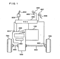
- the vehicle is an FF (Front engine Front drive) vehicle.
- the vehicle incorporating the control device for an automatic transmission according to the present embodiment is not limited to the FF vehicle.
- the vehicle includes an engine 1000, a transmission 2000, a planetary gear unit 3000 constituting a portion of transmission 2000, an oil hydraulic circuit 4000 constituting a portion of transmission 2000, a differential gear 5000, a drive shaft 6000, front wheels 7000, and an ECU 8000.
- Engine 1000 is an internal combustion engine that burns a mixture of fuel injected from an injector (not shown) and air, within a combustion chamber of a cylinder. A piston in the cylinder is pushed down by the combustion, whereby a crankshaft is rotated.
- an external combustion engine may be employed.
- a rotating electric machine for example may be employed.
- Transmission 2000 converts the rotational speed of the crankshaft into a desired rotational speed by implementing a desired gear.
- the output gear of transmission 2000 meshes with differential gear 5000.
- planetary gear unit 3000 As to planetary gear unit 3000, a detailed description thereof is given hereinlater.
- Driveshaft 6000 is coupled to differential gear 5000 through spline-fitting for example. Motive power is transmitted to right and left front wheels 7000 via driveshaft 6000.
- a vehicle speed sensor 8002, a position switch 8005 of a shift lever 8004, an accelerator pedal position sensor 8007 of an accelerator pedal 8006, a stop lamp switch 8009 provided at a brake pedal 8008, and an oil temperature sensor 8010 are connected to ECU 8000 via a harness or the like.
- Vehicle speed sensor 8002 senses the vehicle speed from the rotational speed of drive shaft 6000, and transmits a signal representing the sensed result to ECU 8000.
- the position of shift lever 8004 is sensed by position switch 8005, and a signal representing the sensed result is transmitted to ECU 8000.
- a gear of transmission 2000 is automatically implemented corresponding to the position of shift lever 8004. Additionally, the driver may operate to select a manual shift mode in which the driver can select a gear arbitrarily.
- Accelerator pedal position sensor 8007 senses the position of accelerator pedal 8006, and transmits a signal representing the sensed result to ECU 8000.
- Stop lamp switch 8009 senses the ON/OFF state of brake pedal 8008, and transmits a signal representing the sensed result to ECU 8000.
- a stroke sensor sensing the stroke level of brake pedal 8008 may be provided instead of stop lamp switch 8009.
- Oil temperature sensor 8010 senses the temperature of ATF (Automatic Transmission Fluid) of transmission 2000, and transmits a signal representing the sensed result to ECU 8000.
- ECU 8000 controls various devices such that the vehicle attains a desired traveling state based on signals transmitted from vehicle speed sensor 8002, position switch 8005, accelerator pedal position sensor 8007, stop lamp switch 8009, oil temperature sensor 8010, as well as a map and a program stored in a ROM (Read Only Memory).
- ROM Read Only Memory
- Planetary gear unit 3000 is connected to a torque converter 3200 having an input shaft 3100 coupled to the crankshaft.
- Planetary gear unit 3000 includes a first set of the planetary gear mechanism 3300, a second set of the planetary gear mechanism 3400, an output gear 3500, B1, B2, and B3 brakes 3610, 3620 and 3630 fixed to a gear case 3600, C1 and C2 clutches 3640 and 3650, and a one-way clutch F 3660.
- First set 3300 is a single pinion type planetary gear mechanism.
- First set 3300 includes a sun gear S (UD) 3310, a pinion gear 3320, a ring gear R (UD) 3330, and a carrier C (UD) 3340.
- Sun gear S (UD) 3310 is coupled to an output shaft 3210 of torque converter 3200.
- Pinion gear 3320 is rotatably supported on carrier C (UD) 3340. Pinion gear 3320 engages with sun gear S (UD) 3310 and ring gear R (UD) 3300.
- Ring gear R (UD) 3330 is fixed to gear case 3600 by B3 brake 3630.
- Carrier C (UD) 3340 is fixed to gear case 3600 by B1 brake 3610.
- Second set 3400 is a Ravigneaux type planetary gear mechanism.
- Second set 3400 includes a sun gear S (D) 3410, a short pinion gear 3420, a carrier C (1) 3422, a long pinion gear 3430, a carrier C (2) 3432, a sun gear S (S) 3440, and a ring gear R (1) (R (2)) 3450.
- Sun gear S (D) 3410 is coupled to carrier C (UD) 3340.
- Short pinion gear 3420 is rotatably supported on carrier C (1) 3422.
- Short pinion gear 3420 engages with sun gear S (D) 3410 and long pinion gear 3430.
- Carrier C (1) 3422 is coupled with output gear 3500.
- Long pinion gear 3430 is rotatably supported on carrier C (2) 3432. Long pinion gear 3430 engages with short pinion gear 3420, sun gear S (S) 3440, and ring gear R (1) (R (2)) 3450. Carrier C (2) 3432 is coupled with output gear 3500.
- Sun gear S (S) 3440 is coupled to output shaft 3210 of torque converter 3200 by C1 clutch 3640.
- Ring gear R (1) (R (2)) 3450 is fixed to gear case 3600 by B2 brake 3620, and coupled to output shaft 3210 of torque converter 3200 by C2 clutch 3650.
- Ring gear R (1) (R (2)) 3450 is coupled to one-way clutch F 3660, and is disabled in rotation during the drive in first gear.
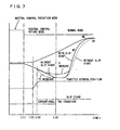
- Fig. 3 is an operation table showing the relation between each transmission gear and respective operation states of the clutches and brakes.
- the mark representing a circle means engagement.
- the mark representing letter X means disengagement.
- the mark representing a double circle means engagement in engine braking condition only.
- the mark representing a triangle means engagement in driving only. According to the combinations shown in this operation table, the brakes and clutches are each operated to implement forward gears including first gear to sixth gear and a reverse gear.
- one-way clutch F 3660 is provided in parallel with B2 brake 3620, it is not necessary to engage B2 brake 3620 in a driving state from the engine side (acceleration) during implementation of first gear (1ST), as indicated by the double circle mark in the operation table.
- one-way clutch F 3660 restrains the rotation of ring gear R (1) (R (2)) 3450.
- one-way clutch F 3660 does not restrain the rotation of ring gear R (1) (R (2)) 3450.
- Torque converter 3200 has a lockup clutch 3203 directly coupling the input shaft and the output shaft, a pump impeller 3201 on the input-shaft side, a turbine impeller 3202 on the output-shaft side, and a stator 3205 having a one-way clutch 3204 and having torque amplifying capability. Torque converter 3200 and the automatic transmission are connected by a rotational shaft.
- the rotational speed NT of the output shaft of torque converter 3200 (turbine rotational speed NT) is detected by a turbine rotational speed sensor.
- the output-shaft rotational speed NOUT of the automatic transmission is detected by an output-shaft rotational speed sensor.
- the operation table in Fig. 3 shows the gear for which the clutch elements that are frictional elements (C1-C2 in the table), the brake elements (B1-B3) and the one-way clutch element (F) are engaged/disengaged.
- the clutch element (C1) and the one-way clutch element (F) are engaged.
- C1 clutch 3640 is particularly referred to as forward travel clutch, input clutch or forward clutch, and is always used in the engaged state for implementing a gear except for the parking (P) position, the reverse (R) position and the neutral (N) position, so as to allow the vehicle to travel forward, as shown the operation table in Fig. 3 .
- C1 clutch 3640 In forward drive (D) position, when it is determined that the vehicle state satisfies predetermined conditions (accelerator-off, brake-on, the brake master cylinder pressure of at least a predetermined value, and the vehicle speed of at most a predetermined value) and thus determined that the vehicle is stopped, C1 clutch 3640 is disengaged to set a predetermined slip state and thereby set a state which is close to the neutral. This control is referred to as neutral control.
- ECU 8000 sets, in returning from the neutral control, lockup clutch 3206 of torque converter 3200 in the slip state to make the slip start.
- a feature of the ECU is to inhibit the slip start until C1 clutch 3640 is engaged. In the following, this feature is described using a flowchart.
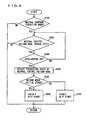
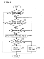
- FIG. 4 a description is given of a control structure of a program executed by ECU 8000 that is the control device of the present embodiment.
- the program shown by the flowchart described below is repeatedly executed at a predetermined cycle time.
- step (hereinafter step is abbreviated as S) 100 ECU 8000 determines whether or not the mode is a neutral control execution mode. When such conditions as: the vehicle is stopped; the accelerator pedal is not depressed; and the brake is operating, are satisfied, the neutral control execution mode is started to disengage C1 clutch 3640. When the mode is the neutral control execution mode (YES in S 100), the process proceeds to S200. Otherwise (NO in S 100), this process is ended.
- ECU 8000 determines whether or not the mode is a neutral control return mode. When such conditions that the vehicle is stopped while the brake is not operating (the depressed brake pedal is not depressed now) are satisfied, the neutral control return mode is started to start to engage C1 clutch 3640. When the mode is the neutral control return mode (YES in S200), the process proceeds to S300. Otherwise (NO in S200), the process is ended.
- ECU 8000 determines whether or not the mode is now the neutral control return mode and the accelerator pedal is depressed to make the accelerator ON. When it is determined that the accelerator is ON (YES in S300), the process proceeds to S400. Otherwise (NO in S300), the process returns to S200.
- ECU 8000 detects the proceeding state of the neutral control return mode. It is detected to what degree C 1 clutch 3640 that was disengaged is now engaged. In the present embodiment, the method of this detection is not limited to a particular one.
- ECU 8000 determines whether or not the mode is an initial stage of the neutral control return mode. When it is determined that the mode is now in the initial stage of the neutral control return mode (YES in S500), the process proceeds to S600. Otherwise (NO in S500), the process proceeds to S700.
- Fig. 5 shows changes with time of engine rotational speed NE, turbine rotational speed NT and the engaging pressure (command pressure) of C1 clutch 3640, when the mode changes from the neutral control execution mode to the neutral control return mode and then to a normal mode.
- Fig. 5 shows the case where the accelerator pedal is not depressed (namely engine rotational speed NE does not change).
- a brake signal is made OFF (YES in S200) and the neutral control return mode is started to cause the engaging pressure (command pressure) of C1 clutch 3640 to temporarily increase to an initial engaging pressure.
- a constant standby pressure is kept and thereafter the pressure is increased with a constant gradient.
- Fig. 6 shows the state (without slip start) where the accelerator pedal is depressed to open the throttle in the neutral control return mode shown in Fig. 5 .
- this is the state where a driver depresses the accelerator pedal at time t (3) immediately after the driver releases the brake pedal at time t (1).
- engine rotational speed NE increases.
- engagement of C1 clutch 3640 is completed.
- turbine rotational speed NT decreases similarly to the decrease shown in Fig. 5 .
- engine torque TE is transmitted via torque converter 3200 to the transmission mechanism (1st gear is implemented) and then transmitted at a desired gear ratio to front wheels that are drive wheels.
- the vehicle is started.
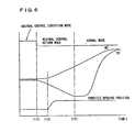
- Fig. 7 shows the state where the accelerator pedal is depressed to open the throttle in the neutral control return mode as shown in Fig. 5 and shows respective cases where the slip start is made and the slip start is not made.
- the mode is now the neutral control return mode (YES in S200) and the accelerator is made ON (YES in S300)
- the proceeding state of the neutral control return mode is detected (S400).
- the slip start is inhibited (S600) and turbine rotational speed NT changes as indicated by the solid line. It is supposed here that the initial state of the neutral control return mode continues to time t (2) (the initial state may continue to any time somewhat earlier than time t (2)).
- the ECU which is the control device for the automatic transmission of the present embodiment
- the slip start is inhibited.
- the durability of the forward clutch can be kept while the engagement shock can be prevented from occurring.
- FIG. 8 a description is given of a control structure of a program executed by ECU 8000 that is the control device of the present embodiment.
- the same process steps as those of the flowchart shown in Fig. 4 are indicated by the same step numbers. Details of these process steps are also identical. Therefore, a detailed description thereof is not repeated here.
- ECU 8000 starts a timer (timer set value is T threshold here).
- T threshold timer set value is T threshold here.
- ECU 8000 determines whether or not count time T of the timer is smaller than T threshold. When count time T of the timer is smaller than T threshold, namely there is no time-up, the process proceeds to S600. Otherwise (NO in S1100), the process proceeds to S700.
- the timer monitors the period from the time of the neutral control return to the time when the hydraulic pressure is applied for engaging the forward clutch to allow the forward clutch to be engaged.
- a predetermined time passes from the start of the return from the neutral control, it is determined that the initial state has ended, and thus the slip start can be permitted. Otherwise, the slip start is inhibited to suppress the engagement shock of the forward clutch and improve the durability of the forward clutch.
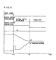
- FIG. 9 a description is given of a control structure of a program executed by ECU 8000 that is a control device of the present embodiment.
- the same process steps as those of the flowchart shown in Fig. 4 are indicated by the same step numbers. Details of these process steps are also identical. Therefore, a detailed description thereof is not repeated here.
- ECU 8000 detects turbine rotational speed NT.
- ECU 8000 determines whether or not turbine rotational speed NT is larger than NT threshold. When turbine rotational speed NT is still larger than NT threshold (YES in 52100), the process proceeds to S600. Otherwise (NO in S2100), the process proceeds to S700.
- turbine rotational speed NR decreases. Therefore, after starting the return from the neutral control, change of turbine rotational speed NT is detected.
- turbine rotational speed NT becomes equal to or smaller than NT threshold, it is determined that the initial state is ended, and thus the slip start can be permitted. Otherwise, the slip start is inhibited to suppress engagement shock of the forward clutch and improve the durability of the forward clutch.
Claims (6)
- Steuerungsvorrichtung für ein Automatikgetriebe mit einem Einrückelement, das eingerückt ist, wenn ein Fahrzeug gestartet wird,
wobei das Automatikgetriebe einen Drehmomentwandler mit einer Überbrückungskupplung und einem Getriebemechanismus aufweist,
wobei die Steuerungsvorrichtung aufweist:eine Leerlaufsteuerungs-Ausführeinrichtung zum Steuern des Getriebemechanismus, um das Einrückelement in einem Fall auszurücken, in dem das Fahrzeug in einer Vorwärtsfahrposition sich in einem Zustand befindet, der eine vorbestimmte Bedingung erfüllt, und dementsprechend anhält;eine Leerlaufsteuerungs-Rückkehreinrichtung zum Steuern des Getriebemechanismus, so dass das Einrückelement in einem Fall eingerückt wird,in dem das Fahrzeug sich in einem Zustand befindet, der eine andere vorbestimmte Bedingung erfüllt;eine Startsteuerungseinrichtung zum Steuern der Überbrückungskupplung, so dass die Überbrückungskupplung in einen Rutschzustand versetzt wird, wenn die Rückkehr von der Leerlaufsteuerung erfolgt und das Fahrzeug gestartet wird,wobei die Steuerungsvorrichtung dadurch gekennzeichnet ist, dass sie ferner aufweist:eine Erfassungseinrichtung zum Erfassen eines Zustands der Rückkehr von der Leerlaufsteuerung; undeine Bestimmungseinrichtung zum Bestimmen, basierend auf dem Zustand der Rückkehr von der Leerlaufsteuerung, ob die Überbrückungskupplung durch die Startsteuerungseinrichtung gesteuert werden soll oder nicht, wobeidie Bestimmungseinrichtung eine Einrichtung zum Bestimmen beinhaltet, um die Steuerung durch die Startsteuerungseinrichtung zu verhindern, wenn sich die Rückkehr von der Leerlaufsteuerung in einem Initialzustand befindet. - Steuerungsvorrichtung nach Anspruch 1, wobei
die Bestimmungseinrichtung eine Einrichtung zum Bestimmen beinhaltet, um die Steuerung durch die Startsteuerungseinheit auszuführen, wenn die Rückkehr von der Leerlaufsteuerung einen Initialzustand durchlaufen hat. - Steuerungsvorrichtung nach Anspruch 1 oder 2, wobei
die Bestimmungseinrichtung eine Einrichtung zum basierend auf einem Einrückzustand des Einrückelements erfolgenden Bestimmen, ob die Rückkehr von der Leerlaufsteuerung in einem Initialzustand erfolgt oder den Initialzustand durchlaufen hat, und zum Bestimmen, dass, wenn die Rückkehr von der Leerlaufsteuerung den Initialzustand durchlaufen hat, die Steuerung durch die Startsteuerungseinrichtung ausgeführt wird, beinhaltet. - Steuerungsvorrichtung nach einem der vorhergehenden Ansprüche, wobei
die Bestimmungseinrichtung eine Einrichtung zum Bestimmen, dass, wenn eine vorbestimmte Zeit ab dem Start der Rückkehr von der Leerlaufsteuerung vergangen ist, die Rückkehr von der Leerlaufsteuerung den Initialzustand durchlaufen hat, und zum Bestimmen, dass die Steuerung durch die Startsteuerungseinrichtung ausgeführt wird, beinhaltet. - Steuerungsvorrichtung nach einem der vorhergehenden Ansprüche, wobei
die Bestimmungseinrichtung eine Einrichtung zum Bestimmen, dass, wenn eine Turbinendrehzahl zumeist einer vorbestimmten Drehzahl entspricht, der Initialzustand durchlaufen worden ist, und zum Bestimmen, dass die Steuerung durch die Startsteuerungseinrichtung ausgeführt wird, beinhaltet. - Automatikgetriebe, aufweisend die Steuerungsvorrichtung nach einem der vorhergehenden Ansprüche.
Applications Claiming Priority (2)
| Application Number | Priority Date | Filing Date | Title |
|---|---|---|---|
| JP2005069616A JP4760065B2 (ja) | 2005-03-11 | 2005-03-11 | 自動変速機の制御装置 |
| PCT/JP2006/305195 WO2006095920A1 (ja) | 2005-03-11 | 2006-03-09 | 自動変速機の制御装置 |
Publications (3)
| Publication Number | Publication Date |
|---|---|
| EP1857715A1 EP1857715A1 (de) | 2007-11-21 |
| EP1857715A4 EP1857715A4 (de) | 2011-07-13 |
| EP1857715B1 true EP1857715B1 (de) | 2012-11-14 |
Family
ID=36953500
Family Applications (1)
| Application Number | Title | Priority Date | Filing Date |
|---|---|---|---|
| EP06715686A Expired - Fee Related EP1857715B1 (de) | 2005-03-11 | 2006-03-09 | Automatikgetriebesteuervorrichtung |
Country Status (6)
| Country | Link |
|---|---|
| US (1) | US7769516B2 (de) |
| EP (1) | EP1857715B1 (de) |
| JP (1) | JP4760065B2 (de) |
| KR (1) | KR100875864B1 (de) |
| CN (1) | CN100498015C (de) |
| WO (1) | WO2006095920A1 (de) |
Families Citing this family (27)
| Publication number | Priority date | Publication date | Assignee | Title |
|---|---|---|---|---|
| DE102005027098A1 (de) * | 2005-06-11 | 2006-12-14 | Zf Friedrichshafen Ag | Verfahren zum Schalten eines Kraftfahrzeug-Automatikgetriebes mit hydrodynamischem Drehmomentwandler beim Anhalten des Fahrzeuges |
| JP4978394B2 (ja) | 2007-09-19 | 2012-07-18 | トヨタ自動車株式会社 | 車両の制御装置、制御方法およびその方法をコンピュータに実現させるプログラムならびにそのプログラムを記録した記録媒体 |
| JP4349464B2 (ja) * | 2008-03-13 | 2009-10-21 | トヨタ自動車株式会社 | 車両用駆動装置 |
| JP5012734B2 (ja) * | 2008-08-29 | 2012-08-29 | アイシン・エィ・ダブリュ株式会社 | 自動変速機の制御装置及び自動変速機の制御方法 |
| JP5261224B2 (ja) * | 2009-02-12 | 2013-08-14 | トヨタ自動車株式会社 | 車両用自動変速機の制御装置 |
| US8401768B2 (en) | 2009-09-01 | 2013-03-19 | Ford Global Technologies, Llc | System and method for restarting an engine |
| US8795135B2 (en) | 2009-09-01 | 2014-08-05 | Ford Global Technologies, Llc | Method for controlling an engine during a restart |
| JP5377352B2 (ja) * | 2010-02-05 | 2013-12-25 | トヨタ自動車株式会社 | 車両用動力伝達装置の発進制御装置 |
| US8880310B2 (en) * | 2010-03-31 | 2014-11-04 | Aisin Aw Co., Ltd. | Control device of automatic transmission |
| DE112011100173T5 (de) | 2010-03-31 | 2012-10-31 | Aisin Aw Co., Ltd. | Steuervorrichtung eines automatikgetriebes |
| JP5387481B2 (ja) * | 2010-03-31 | 2014-01-15 | アイシン・エィ・ダブリュ株式会社 | 自動変速機の制御装置 |
| JP5729379B2 (ja) * | 2010-03-31 | 2015-06-03 | アイシン・エィ・ダブリュ株式会社 | 自動変速機の制御装置 |
| CN101885332B (zh) * | 2010-06-22 | 2012-08-29 | 重庆长安汽车股份有限公司 | 汽车at变速器制动辅助控制方法 |
| JP5593908B2 (ja) * | 2010-07-20 | 2014-09-24 | トヨタ自動車株式会社 | ロックアップクラッチの制御装置 |
| WO2013011579A1 (ja) * | 2011-07-20 | 2013-01-24 | トヨタ自動車株式会社 | 車両の制御装置 |
| CN102635692B (zh) * | 2012-01-16 | 2015-05-20 | 浙江吉利汽车研究院有限公司 | 一种汽车自动变速器离合器空挡停止装置 |
| JP6094192B2 (ja) * | 2012-12-11 | 2017-03-15 | 三菱自動車工業株式会社 | シフト装置 |
| DE102013001019A1 (de) * | 2013-01-22 | 2014-07-24 | GM Global Technology Operations LLC (n. d. Ges. d. Staates Delaware) | Verfahren zum Auslösen eines Warnsignals bei einem Fehlverhalten beim Betrieb eines Kraftfahrzeugs |
| KR101714595B1 (ko) * | 2013-03-11 | 2017-03-09 | 도요타 지도샤(주) | 자동 변속기의 제어 장치 |
| JP5644922B2 (ja) * | 2013-09-19 | 2014-12-24 | トヨタ自動車株式会社 | 車両用動力伝達装置の発進制御装置 |
| CN106030161B (zh) * | 2014-02-28 | 2017-08-25 | 爱信艾达株式会社 | 车辆用驱动装置的控制装置 |
| US10202120B2 (en) | 2016-06-01 | 2019-02-12 | Ford Global Technologies, Llc | Methods and system for decelerating a vehicle |
| US10011283B2 (en) | 2016-06-28 | 2018-07-03 | Ford Global Technologies, Llc | System and method for driving vehicle accessories |
| US10017182B2 (en) | 2016-06-28 | 2018-07-10 | Ford Global Technologies, Llc | System and method for controlling a torque converter clutch |
| US10322725B2 (en) | 2016-07-14 | 2019-06-18 | Ford Global Technologies, Llc | Powertrain lash management |
| US10295054B2 (en) * | 2016-10-28 | 2019-05-21 | Ford Global Technologies, Llc | Method and control for operating transmission during clutch failure when shifting from gear to neutral |
| KR101809257B1 (ko) | 2016-12-12 | 2018-01-18 | 한국지질자원연구원 | 차동기어를 이용한 회생제동 하이브리드 변속기 및 이의 작동방법 |
Family Cites Families (9)
| Publication number | Priority date | Publication date | Assignee | Title |
|---|---|---|---|---|
| JPH0672661B2 (ja) * | 1983-01-27 | 1994-09-14 | マツダ株式会社 | 自動変速機のロツクアツプ制御装置 |
| JPS6155455A (ja) * | 1984-08-24 | 1986-03-19 | Toyota Motor Corp | 車輌用自動変速機のアイドル運転時制御方法 |
| JPS6283537A (ja) * | 1985-10-07 | 1987-04-17 | Toyota Motor Corp | 車輛用自動変速機のアイドル運転時制御方法 |
| DE19705956C1 (de) * | 1997-02-17 | 1998-02-19 | Zahnradfabrik Friedrichshafen | Verfahren zur Regelung einer Wandlerkupplung bei einem Anfahrvorgang |
| JP2000304125A (ja) * | 1999-04-16 | 2000-11-02 | Mitsubishi Motors Corp | 自動変速機の制御装置 |
| US6634988B2 (en) * | 2001-01-23 | 2003-10-21 | General Motors Corporation | Transmission shift control |
| JP2002256921A (ja) * | 2001-02-28 | 2002-09-11 | Toyota Motor Corp | 車両の制御装置 |
| JP3873905B2 (ja) * | 2003-02-27 | 2007-01-31 | マツダ株式会社 | 変速機の制御装置 |
| JP2005003193A (ja) * | 2003-05-16 | 2005-01-06 | Toyota Motor Corp | 車両用ロックアップクラッチの制御装置 |
-
2005
- 2005-03-11 JP JP2005069616A patent/JP4760065B2/ja not_active Expired - Fee Related
-
2006
- 2006-03-09 KR KR1020077010130A patent/KR100875864B1/ko not_active IP Right Cessation
- 2006-03-09 EP EP06715686A patent/EP1857715B1/de not_active Expired - Fee Related
- 2006-03-09 CN CNB2006800009809A patent/CN100498015C/zh not_active Expired - Fee Related
- 2006-03-09 WO PCT/JP2006/305195 patent/WO2006095920A1/ja active Application Filing
- 2006-03-09 US US11/661,856 patent/US7769516B2/en not_active Expired - Fee Related
Also Published As
| Publication number | Publication date |
|---|---|
| KR100875864B1 (ko) | 2008-12-26 |
| US20080172161A1 (en) | 2008-07-17 |
| WO2006095920B1 (ja) | 2006-11-02 |
| US7769516B2 (en) | 2010-08-03 |
| EP1857715A1 (de) | 2007-11-21 |
| JP4760065B2 (ja) | 2011-08-31 |
| CN101040135A (zh) | 2007-09-19 |
| JP2006250287A (ja) | 2006-09-21 |
| WO2006095920A1 (ja) | 2006-09-14 |
| CN100498015C (zh) | 2009-06-10 |
| KR20070064656A (ko) | 2007-06-21 |
| EP1857715A4 (de) | 2011-07-13 |
Similar Documents
| Publication | Publication Date | Title |
|---|---|---|
| EP1857715B1 (de) | Automatikgetriebesteuervorrichtung | |
| EP2192331B1 (de) | Steuerungsvorrichtung und steuerungsverfahren für ein stufenloses getriebe | |
| US20030203790A1 (en) | Vehicle drive control apparatus and method | |
| US8046143B2 (en) | Automatic gear control device | |
| US10495222B2 (en) | Automatic transmission control device and control method | |
| US7632210B2 (en) | Device and method for controlling an automatic transmission | |
| US20180073632A1 (en) | Automatic transmission control device and control method | |
| EP1855031B1 (de) | Steuervorrichtung für automatikgetriebe | |
| JP2008045565A (ja) | 車両の制御装置 | |
| JPH0587236A (ja) | 車両のクリープ制御装置 | |
| JP2005219672A (ja) | 車両用動力伝達装置のエンジン制御装置 | |
| JP2001021029A (ja) | 車両用自動変速機の変速制御方法 | |
| JP4622501B2 (ja) | 自動変速機の制御装置 | |
| JP4924015B2 (ja) | 自動変速機の制御装置 | |
| JP2008101697A (ja) | パワートレーンの制御装置、制御方法、その方法を実現させるプログラムおよびそのプログラムを記録した記録媒体 | |
| JP2008038613A (ja) | 車両の制御装置 | |
| JP2009097614A (ja) | 自動変速機の制御装置 |
Legal Events
| Date | Code | Title | Description |
|---|---|---|---|
| PUAI | Public reference made under article 153(3) epc to a published international application that has entered the european phase |
Free format text: ORIGINAL CODE: 0009012 |
|
| 17P | Request for examination filed |
Effective date: 20070906 |
|
| AK | Designated contracting states |
Kind code of ref document: A1 Designated state(s): DE FR GB |
|
| DAX | Request for extension of the european patent (deleted) | ||
| RBV | Designated contracting states (corrected) |
Designated state(s): DE FR GB |
|
| A4 | Supplementary search report drawn up and despatched |
Effective date: 20110615 |
|
| RIC1 | Information provided on ipc code assigned before grant |
Ipc: F16H 59/18 20060101ALI20110608BHEP Ipc: B60W 10/10 20060101ALI20110608BHEP Ipc: F16H 61/14 20060101ALI20110608BHEP Ipc: F16H 59/56 20060101ALI20110608BHEP Ipc: F16H 59/10 20060101ALI20110608BHEP Ipc: F16H 1/14 20060101ALI20110608BHEP Ipc: F16H 45/00 20060101ALI20110608BHEP Ipc: B60W 10/02 20060101ALI20110608BHEP Ipc: F16H 61/20 20060101AFI20070822BHEP |
|
| GRAP | Despatch of communication of intention to grant a patent |
Free format text: ORIGINAL CODE: EPIDOSNIGR1 |
|
| RIC1 | Information provided on ipc code assigned before grant |
Ipc: F16H 61/20 20060101AFI20120223BHEP Ipc: F16H 59/10 20060101ALI20120223BHEP Ipc: F16H 59/18 20060101ALI20120223BHEP Ipc: F16H 1/14 20060101ALI20120223BHEP Ipc: B60W 10/10 20120101ALI20120223BHEP Ipc: F16H 59/56 20060101ALI20120223BHEP Ipc: B60W 10/02 20060101ALI20120223BHEP Ipc: F16H 61/14 20060101ALI20120223BHEP Ipc: F16H 45/00 20060101ALI20120223BHEP |
|
| RIN1 | Information on inventor provided before grant (corrected) |
Inventor name: ASAMI, TOMOHIRO C/O TOYOTA JIDOSHA KABUSHIKI KAISH Inventor name: KONDO, TAKAHIRO C/O TOYOTA JIDOSHA KABUSHIKI KAIS Inventor name: NAKAYASHIKI, MAKOTO C/O TOYOTA JIDOSHA KABUSHIKI K Inventor name: MINAKI, SHUN C/O TOYOTA JIDOSHA KABUSHIKI KAISHA |
|
| GRAS | Grant fee paid |
Free format text: ORIGINAL CODE: EPIDOSNIGR3 |
|
| GRAA | (expected) grant |
Free format text: ORIGINAL CODE: 0009210 |
|
| AK | Designated contracting states |
Kind code of ref document: B1 Designated state(s): DE FR GB |
|
| REG | Reference to a national code |
Ref country code: GB Ref legal event code: FG4D |
|
| REG | Reference to a national code |
Ref country code: DE Ref legal event code: R096 Ref document number: 602006033036 Country of ref document: DE Effective date: 20130110 |
|
| RAP2 | Party data changed (patent owner data changed or rights of a patent transferred) |
Owner name: TOYOTA JIDOSHA KABUSHIKI KAISHA |
|
| PLBE | No opposition filed within time limit |
Free format text: ORIGINAL CODE: 0009261 |
|
| STAA | Information on the status of an ep patent application or granted ep patent |
Free format text: STATUS: NO OPPOSITION FILED WITHIN TIME LIMIT |
|
| 26N | No opposition filed |
Effective date: 20130815 |
|
| REG | Reference to a national code |
Ref country code: DE Ref legal event code: R097 Ref document number: 602006033036 Country of ref document: DE Effective date: 20130815 |
|
| PGFP | Annual fee paid to national office [announced via postgrant information from national office to epo] |
Ref country code: FR Payment date: 20140311 Year of fee payment: 9 |
|
| PGFP | Annual fee paid to national office [announced via postgrant information from national office to epo] |
Ref country code: GB Payment date: 20140305 Year of fee payment: 9 |
|
| PGFP | Annual fee paid to national office [announced via postgrant information from national office to epo] |
Ref country code: DE Payment date: 20140417 Year of fee payment: 9 |
|
| REG | Reference to a national code |
Ref country code: DE Ref legal event code: R119 Ref document number: 602006033036 Country of ref document: DE |
|
| GBPC | Gb: european patent ceased through non-payment of renewal fee |
Effective date: 20150309 |
|
| REG | Reference to a national code |
Ref country code: FR Ref legal event code: ST Effective date: 20151130 |
|
| PG25 | Lapsed in a contracting state [announced via postgrant information from national office to epo] |
Ref country code: DE Free format text: LAPSE BECAUSE OF NON-PAYMENT OF DUE FEES Effective date: 20151001 Ref country code: GB Free format text: LAPSE BECAUSE OF NON-PAYMENT OF DUE FEES Effective date: 20150309 |
|
| PG25 | Lapsed in a contracting state [announced via postgrant information from national office to epo] |
Ref country code: FR Free format text: LAPSE BECAUSE OF NON-PAYMENT OF DUE FEES Effective date: 20150331 |