EP1855328B1 - Thermoelectric power generator with built-In temperature adjustment - Google Patents
Thermoelectric power generator with built-In temperature adjustment Download PDFInfo
- Publication number
- EP1855328B1 EP1855328B1 EP07251930.9A EP07251930A EP1855328B1 EP 1855328 B1 EP1855328 B1 EP 1855328B1 EP 07251930 A EP07251930 A EP 07251930A EP 1855328 B1 EP1855328 B1 EP 1855328B1
- Authority
- EP
- European Patent Office
- Prior art keywords
- thermoelectric module
- cooling
- heat
- heat sink
- temperature
- Prior art date
- Legal status (The legal status is an assumption and is not a legal conclusion. Google has not performed a legal analysis and makes no representation as to the accuracy of the status listed.)
- Active
Links
Images


Classifications
-
- H—ELECTRICITY
- H10—SEMICONDUCTOR DEVICES; ELECTRIC SOLID-STATE DEVICES NOT OTHERWISE PROVIDED FOR
- H10N—ELECTRIC SOLID-STATE DEVICES NOT OTHERWISE PROVIDED FOR
- H10N10/00—Thermoelectric devices comprising a junction of dissimilar materials, i.e. devices exhibiting Seebeck or Peltier effects
- H10N10/10—Thermoelectric devices comprising a junction of dissimilar materials, i.e. devices exhibiting Seebeck or Peltier effects operating with only the Peltier or Seebeck effects
- H10N10/13—Thermoelectric devices comprising a junction of dissimilar materials, i.e. devices exhibiting Seebeck or Peltier effects operating with only the Peltier or Seebeck effects characterised by the heat-exchanging means at the junction
Definitions
- the present disclosure relates to electrical power systems, and more specifically, to generating electrical power using thermoelectric modules.
- thermoelectric effect is the conversion of a thermal differential between opposing surfaces of a thermoelectric material to electric voltage, and vice versa.
- the thermoelectric effect forms of which are known as the "Peltier effect” or the “Seebeck effect,” for one example, is the technology used in small electrical refrigeration systems used in portable beverage coolers and cars.
- Applying a voltage across a thermoelectric module causes a current to be driven through the semiconducting material of the thermoelectric module.
- the flow of current through the thermoelectric module causes the thermoelectric module to draw heat from a cooling side of the thermoelectric module to an opposing surface of the module.
- the cooling side is coupled with an enclosure that serves as a solid-state cooling device.
- thermoelectric effect also can be used to generate electric voltage by disposing thermoelectric modules where one surface will be exposed to a relatively hot temperature, while an opposing surface will be exposed to a relatively cold temperature; instead of the voltage causing the thermal differential, the thermal differential is used to generate electric voltage.
- FIGURE 1 depicts a thermoelectric module 100 used to generate electric voltage.
- the thermoelectric module 100 is situated between a hot thermal source 110 and a cold thermal source 120, creating a thermal differential ⁇ H 130 between a first surface 140 of the thermoelectric module 100 presented to the hot thermal source 110 and a second surface 150 of the thermoelectric module 100 presented to the cold thermal source 120.
- the thermoelectric module 100 generates a voltage differential ⁇ V 160.
- thermoelectric modules to generate electrical power involves a number of concerns.
- Third, currently available thermoelectric modules are relatively fragile. Thus, in attempting to expose one surface of a thermoelectric module to a very hot environment in order to create a very high thermal differential, the high heat may damage the thermoelectric module.
- thermoelectric modules There is growing interest in using thermoelectric modules to generate power. After all, countless engines, motors, furnaces, lights, electrical circuits, and other devices generate waste heat as a byproduct of their operation. Moreover, energy must be expended to cool these engines and other devices to keep them functioning or protect them from being damaged. Similarly, natural sources of heat, such as geothermal sources generate heat that represents a wasted opportunity for the generation of power. If this wasted or excess heat could be harnessed with thermoelectric modules, electrical energy could be generated from otherwise unused heat sources. Unfortunately, problems in maintaining sufficient thermal differentials, preventing excessive thermal differentials, or simply being unable to regulate thermal differentials undermines the practicality and effectiveness of using thermoelectric modules to generate electrical power.
- US-B2-6,747,572 relates to an autonomous sensor system provided for powering sensors using thermoelectric modules driven by thermal energy. US-B2-6,747,572 discloses the features of the pre-characterising portion of claim 1.
- JP-A-10/290,590 relates to a thermoelectric conversion module to which the quantity of heat transferred from combustion exhaust gas is controlled so that the high-temperature side of the thermoelectric conversion module may be under the set temperature corresponding to the heat-resistant temperature of the thermoelectric elements.
- thermoelectric module As set out in claim 1.
- thermoelectric module as set out in claim 3.
- Embodiments of the present invention are related to regulating a temperature of a thermoelectric module presented to a heat source. By regulating the temperature of the thermoelectric module or the thermal differential across the thermoelectric module, the output voltage of the thermoelectric module can be regulated, and the thermoelectric module can be protected from damage.
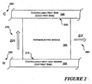
- FIGURE 2 is a general, schematic view of a thermoelectric module 200 with which an embodiment of the invention is used.
- a first surface 210 of the thermoelectric module 200 is presented to an input heat source 220.
- the input heat source 220 in one mode, is a source of waste heat, such as an engine coolant line or an engine exhaust.
- the input heat source 220 may include a "hot" heat sink that conveys heat from a principal heat source.
- the principal heat source is an engine
- the input heat source 220 may include a heat sink that conveys heat from an exhaust line or cooling line running from the engine block.
- Embodiments of the invention may include a controllable heat sink or heat source allowing the heat conveyed to the heat sink to be regulated, for example, to prevent thermal damage to the thermoelectric module 200.
- thermoelectric module 200 A second surface 230 of the thermoelectric module 200 is presented to a controllable heat sink 240.
- a difference between a temperature H 250 of the input heat source 220 and a temperature C 260 of the controllable heat sink 240 results in a thermal differential ⁇ H 270.
- the thermal differential ⁇ H 270 applied across the thermoelectric module 200 results in a voltage differential ⁇ V 280.
- the voltage differential ⁇ V 280 is proportional to the thermal differential ⁇ H 270.
- the temperature H 250 typically will vary. As previously described, the variation of the temperature H 250 may present problems if the temperature H 250 is either too low or too high.
- the controllable heat sink 240 allows for the temperature C 260 to be varied to change the thermal differential ⁇ H 270.
- the controllable heat sink 240 can be cooled to reduce the temperature C 260 and increase the thermal differential ⁇ H 270.
- the temperature of the controllable heat sink H 220 can be cooled to protect the thermoelectric module 200 from damage.
- the temperature C 260 of the controllable heat sink can be increased to reduce the thermal differential ⁇ H 270 and, in turn, reduce the voltage differential ⁇ V 280.
- the input heat source 220 could be controllably coupled with the controllable heat sink 240 to reduce the thermal differential across the thermoelectric module 200.
- the input heat source 220 includes a heat sink conveying heat from a principal heat source
- the heat conveyed from the principal heat source may also be regulated to control the heat applied to the thermoelectric module 200, as well as to regulate the thermal differential ⁇ H 270 applied across the thermoelectric module 200.
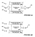
- FIGURE 3A illustrates an exemplary case when the temperature H 300 presented by the heat source 220 is lower than desired.
- the input heat source 220 may include a controlled or uncontrolled heat source. Because the temperature H 300 is lower than desired, the thermal differential ⁇ H 310 between the temperature H 300 and the temperature C 320 across the thermoelectric module 200 yields a resulting voltage differential ⁇ V 330 lower than desired.
- FIGURE 3B illustrates how, using one embodiment, the temperature C 350 of the controllable heat sink 240 is reduced, causing an increased thermal differential ⁇ H 360 with no change in the temperature H 300 of the heat source 220.
- the increased thermal differential ⁇ H 360 yields an increased voltage differential ⁇ V 370 across the thermoelectric module 200.
- FIGURE 4A illustrates an exemplary case in which the temperature H 400 presented by the heat source 220 is higher than desired.
- the thermal differential ⁇ H 410 between the temperature H 400 and the temperature C 420 across the thermoelectric module 200 becomes higher than intended or desired, resulting in a voltage differential ⁇ V 430 that also is higher than is desired or intended.
- a change in the voltage differential is not necessarily a linear response as a result of a change in a thermal differential. Accordingly, thermal adjustments applied to adjust for changes in the temperature H 400 should consider the voltage differential-to-thermal differential response of the thermoelectric module.
- FIGURE 4B illustrates how the temperature C 450 of the controllable heat sink 240 is increased, causing a reduced thermal differential ⁇ H 460 with no change in the temperature H 400 of the heat source 220.
- the reduced thermal differential ⁇ H 460 yields a reduced voltage differential ⁇ V 470 across the thermoelectric module 200.
- the heat source 220 includes an input heat sink conveying heat from a principal heat source
- the heat conveyed from the principal heat source to the heat sink can be regulated, as described further below.
- regulating the heat conveyed to the input heat source 220 can reduce the heat applied to the thermoelectric module to protect the thermoelectric module from damage, or adjust the thermal differential ⁇ H 460 to cause a reduced voltage differential ⁇ V 370 across the thermoelectric module 200.
- the temperature of the controllable heat sink 240 can be adjusted to change the thermal differential across the thermoelectric module 200 to account for variations in the heat supplied by the heat source 220.
- the thermal differential thus can be changed to change the resulting voltage differential.
- the temperature applied by the controllable heat sink 240 can be adjusted to reduce the temperature or the thermal differential to which the thermoelectric module 200 is subjected to reduce damage to the thermoelectric module.
- the heat conveyed from the principal heat source to the heat sink can be regulated to reduce the temperature or the thermal differential to which the thermoelectric module 200 is subjected to reduce damage to the thermoelectric module.
- the controllable heat sink may be manifested in a number of forms, and the temperature of the controllable heat sink may be controlled using a variety of systems.
- the cooling system may include a fluid cooled system, in which the fluid may be in a gaseous or a liquid form. Also, as is described further below, it may be desirable to employ a control system to direct the operations of the cooling system.
- the control system can monitor the operating conditions of the thermoelectric module, and as a result of those conditions, adjust the cooling applied to the controllable heat sink to adjust or maintain the thermal differential across the thermoelectric module.
- FIGURES 5A and 5B illustrate heat sinks that are suitable for an air-cooled or other gas-cooled system.
- FIGURE 5A shows a heat sink 500 that includes a planar block 510 that supports a plurality of cooling fins 520. Both the planar block 510 and the cooling fins 520 are composed of a thermally-conductive material, such as copper, or an aluminum alloy.
- the planar block 510 is disposed on the component to be cooled.
- the planar block 510 conveys heat generated by the component to the fins 520.
- the fins 520 which present an increased surface area for the disbursal of heat, radiate the heat to the environment surrounding the fins 520.
- FIGURE 5B shows a heat sink 550 that includes a planar block 560 that supports one or more heat pipes 570 that disburse heat from the planar block.
- the heat pipe 570 may include a plurality of fins 580 at an end removed from the planar block 560 to further facilitate temperature transfer.
- the heat pipe 570 is a hollow, enclosed tube in which a coolant, such as water, ethanol, or mercury is enclosed.
- a coolant such as water, ethanol, or mercury
- the heat sinks 500 and 550 are two exemplary forms of heat sinks; other types of heat sinks also are suitable for an embodiment of a controllable heat sink using air-cooling or gas-cooling.
- Embodiments of the invention may also employ vapor chamber heat sinks or any other desired form of heat sinks for applying thermal adjustments to the thermoelectric module. Embodiments of the invention are not limited to the use of any particular selected form of heat sink.
- FIGURES 6A and 6B illustrate exemplary embodiments of systems for applying thermal adjustments to thermoelectric modules to protect the modules from damage, control the voltage output of the modules, or to address other operating concerns.
- the systems of FIGURES 6A and 6B both include, but do not show, original heat sources used to develop the thermal differential that supports the thermoelectric effect exploited by the thermoelectric modules.
- Many original heat sources may be used.
- the engine that motivates the vehicle will generate heat both as a result of cooling the engine and in the engine's exhaust. Either or both of these heat sources may be exploited to supply heat to facilitate a thermoelectric effect.
- thermoelectric effect a phenomena that can be used to facilitate a thermoelectric effect.
- naturally occurring phenomena such as radiant heat from the Earth or the Sun, or geothermal heat in liquid or steam form can be used to facilitate a thermoelectric effect. Any of these heat sources, or any other heat source, can be tapped to facilitate a thermoelectric effect.
- the input heat sinks or heat sources shown convey heat from the original heat source to facilitate the thermoelectric effect.
- the heat conveyed is controlled to apply thermal adjustments to the thermoelectric modules, or the heat conveyed is controlled as part of applying thermal adjustments to the thermoelectric modules.
- FIGURE 6A illustrates a cooling system 600 suitable for transferring heat from a thermoelectric module 602 equipped with a controllable heat sink 604.
- the controllable heat sink 604 is disposed in a gaseous cooling loop 606.
- gas is heated to an elevated temperature C ⁇ 608.
- the gas at the elevated temperature C ⁇ 608 is circulated by convection, a fan, or other motivating force (not shown) until it is exposed to a cooling gas source 612.
- the cooling gas source 612 cools the gas to a reduced temperature C ⁇ 610, where it circulates via the cooling loop 606 to draw heat from the heat sink 604.
- the cooling system 600 includes a control unit 614 that is coupled with a sensor 616 that monitors operating conditions of the thermoelectric module 602.
- the control unit may include a thermostat or another type of control logic operable to direct a cooling mechanism 618 to control the degree of cooling applied within the cooling loop 606 based on the operating conditions.
- the sensor 616 may monitor the operating temperature of the thermoelectric module 602, including the environmental temperature attending the thermoelectric module 602, or the surface temperature of the thermoelectric module 602.
- the sensor 616 may monitor the voltage generated by the thermoelectric module 602 as indicative of the thermal differential to which the thermoelectric module 602 is exposed.
- the cooling mechanism 618 may include a controlled port, a fan, or another mechanism the control unit 614 directs in response to the operating conditions read from the sensor 616.
- the cooling mechanism 618 may include a fan mechanically engaged to an engine to take advantage of the operation of the engine to motivate a flow from the cooling gas source 612 to the cooling cycle.
- the fan may include a clutch mechanism to selectively increase the air flow based on signals from the control unit 614. The clutch mechanism could be selectively engaged and geared by the control unit in order to control the thermal adjustment applied by the fan.
- the control unit 614 engages the cooling mechanism 618 to increase the contact of the cooling gas source 612 with the cooling cycle 606. Conversely, if less cooling is needed, the control unit 614 can engage the cooling mechanism 618 to reduce the exposure of the cooling cycle 606.
- the cooling mechanism 618 may include a panel that exposes the cooling cycle 606 to ambient air as a cooling gas source 612. Because jet engines operate at high altitudes where the ambient air is quite cold and inherently flows by at very high speeds, controlling the area of the cooling loop 606 exposed to the cooling gas source 612 may be affected by selectively opening or closing a panel to the outside air.
- the control unit 614 also is coupled with a control 622 operable to control the heat supplied to the input heat sink or heat source 620 from an original heat source (not shown).
- a control 622 operable to control the heat supplied to the input heat sink or heat source 620 from an original heat source (not shown).
- the control unit can reduce the heat applied to the thermoelectric module and change the thermal differential applied to the input heat sink or heat source.
- the control 622 may include a valve or similar control that can be used to reduce the heat conveyed to the input heat sink or heat source 620.
- FIGURE 6B illustrates another cooling system 650 suitable for controlling the thermal differential applied to a thermoelectric module 652 by controlling the heat applied to each of the surfaces of the thermoelectric module.
- the cooling system 650 transfers heat from a thermoelectric module 652 equipped with a secondary heat sink 654.
- the secondary heat sink 654 is disposed in a secondary cooling loop 656, which may include a gaseous or a liquid cooling loop.
- cooling fluid either gaseous or liquid, is heated to an elevated temperature C ⁇ 658.
- the fluid at the elevated temperature C ⁇ 658 is circulated by convection, a fan, or other motivating force (not shown) until it is exposed to a cooling source 662.
- the cooling source 662 cools the fluid to a reduced temperature C ⁇ 660, where it circulates via the secondary cooling loop 656 to draw heat from the secondary heat sink 654.
- the cooling system 650 includes a control unit 664 that is coupled with a secondary sensor 668 that monitors operating conditions of the thermoelectric module 652.
- the control unit 664 may include a thermostat or another type of control logic operable to direct a cooling mechanism 670 to control the degree of cooling applied within the secondary cooling loop 656 based on the operating conditions.
- the secondary sensor 668 may monitor the operating temperature of the thermoelectric module 652, including the environmental temperature attending the thermoelectric module 652, or the surface temperature of the thermoelectric module 652.
- the secondary sensor 668 may monitor the voltage generated by the thermoelectric module 652 as indicative of the thermal differential to which the thermoelectric module 652 is exposed.
- the cooling mechanism 670 may include a controlled port, a fan, or another mechanism the control unit 664 directs in response to the operating conditions read from the sensor 668.
- the cooling mechanism 670 may include a fan mechanically engaged to an engine to take advantage of the operation of the engine to motivate a flow from the cooling source 662 to the cooling cycle.
- the fan may include a clutch mechanism to selectively increase the air flow based on signals from the control unit 664 as previously described with regard to FIGURE 6A .
- the control unit 664 engages the cooling mechanism 670 to increase the contact of the cooling gas source 662 with the cooling cycle 656. Conversely, if less cooling is needed, the control unit 664 can engage the cooling mechanism 670 to reduce the exposure of the cooling cycle 656.
- the operating conditions to which the thermal module 652 is subjected can be regulated by adjusting the heat conveyed to the primary heat sink 680.
- the heat conveyed by the primary heat sink 680 can be regulated in a number of different ways. For example, if the heat is conveyed to the primary heat sink 680 by a fluid, the flow of fluid can be restricted so that the primary heat sink 680 receives less heat.
- the heat conveyed may be regulated by the control unit 664, or another control unit.
- the control unit 664 suitably is coupled with a primary sensor 692 that measures the temperature of the primary heat sink 680, the surface temperature of the thermoelectric module 652, or the attendant temperature about the thermoelectric module 652.
- the control unit 664 may restrict the fluid flow that conveys heat to the primary heat sink 680 when the temperature or thermal differential to which the thermoelectric module 652 is subjected becomes too high.
- the primary heat sink 680 may convey heat from the original heat source (not shown), and the primary heat sink 680 is cooled by another primary cooling loop 682.
- the control unit 664 coupled with the primary sensor 692 monitors operating conditions of the thermoelectric module 652 and controls a cooling mechanism 690 to regulate the cooling of the primary heat sink 680.
- the cooling mechanism 690 may include a controlled port, a fan, or another mechanism the control unit 664 directs in response to the operating conditions read from the primary sensor 692.
- the control unit 664 engages the cooling mechanism 690 to increase the contact of the cooling source 668, which may be the same cooling source used in the secondary cooling loop 656 or a different cooling source.
- the control unit 664 can engage the cooling mechanism 690 to reduce the exposure of the primary cooling cycle 682.
- cooling fluid either gaseous or liquid
- the fluid at the elevated temperature C ⁇ 684 is circulated by convection, a fan, or other motivating force (not shown) until it is exposed to a cooling source 688.
- the cooling source 688 cools the fluid to a reduced temperature C ⁇ 686, where it circulates via the primary cooling loop 682 to draw heat from the primary heat sink 680.
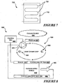
- FIGURES 7-8 illustrate a controllable heat sink and a cooling system in which liquid cooling is used to cool a thermoelectric module.
- FIGURE 7 illustrates a liquid cooled heat sink 700.
- the heat sink 700 includes a planar block 710 that is disposed against the component to be cooled, such as a thermoelectric module.
- the planar block 710 comprises a thermally conductive material to transfer heat from the thermoelectric module to loops of a cooling tube 720.
- the cooling tube 720 receives cooled liquid that absorbs heat from the planar block 710 and carries the heated liquid through a cooling loop as described in connection with FIGURE 8 .
- This type of heat sink is commonly termed a cold plate heat exchanger.
- FIGURE 8 illustrates a liquid cooling system 800 suitable for transferring heat from a thermoelectric module 810 equipped with a heat sink 820.
- the controllable heat sink 820 may include a cold plate heat exchanger as described in connection with FIGURE 7 that is included in a liquid cooling loop 830.
- liquid is heated to an elevated temperature C ⁇ 842.
- the liquid at the elevated temperature C ⁇ 842 is circulated by a pump 870 that circulates the liquid coolant around the cooling loop 830 between the controllable heat sink 820 and a radiator 844.
- the liquid coolant circulates through the radiator 844, which also may be in the nature of the heat sink 700 of FIGURE 7 .
- the cooling source 846 may be the ambient air to which the radiator 844 is exposed.
- the cooling source 846 may include a body of water, such as a river, lake, or ocean, when the thermoelectric module 810 is included in a watercraft or another system that operates adjacent to the body of water, or a hot spring or other liquid geothermal source.
- the cooling source 846 cools the liquid coolant to a reduced temperature C ⁇ 848, where it returns via the cooling loop 830 to draw heat from the heat sink 820.
- the cooling system 800 includes a control unit 850 that is coupled with a sensor 860 that monitors the operating conditions of the thermoelectric module 810.
- the control unit 850 may include a thermostat or another type of control logic operable to direct a cooling mechanism, such as the pump 870, to control the degree of cooling applied within the cooling loop 830 based on the operating conditions.
- the sensor 860 may monitor the operating temperature of the thermoelectric module 810, including the environmental temperature attending the thermoelectric module 810, or the surface temperature of the thermoelectric module 810.
- the sensor 860 may monitor the voltage 880 generated by the thermoelectric module 810 as indicative of the thermal differential to which the thermoelectric module 810 is exposed.
- the pump 870 is an electric pump that is powered, for example, by a portion of the voltage 880 generated by the thermoelectric module 810.
- the pump 870 may include a pump that is mechanically coupled to and driven by an engine, where the pump 870 includes a clutched mechanism controlling the degree of cooling transferred from the cooling source 846 to the radiator 844.
- the clutch or other switching mechanism used to control the pump may be powered by a portion of the voltage 880 generated by the thermoelectric module 810.
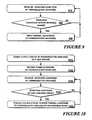
- FIGURES 9 and 10 illustrate modes of adjusting the temperature of a thermoelectric module used to generate power.
- FIGURE 9 is a generalized mode of applying a temperature adjustment to a thermoelectric module.
- operating conditions of one or more thermoelectric modules are monitored.
- the operating conditions may include an ambient temperature attending a thermoelectric module, or a surface temperature of a thermoelectric module.
- the operating conditions may include a voltage output of a thermoelectric module, which is representative of the thermal differential to which the thermoelectric module is subjected.
- thermoelectric module it is determined if the operating conditions are outside the desirable operating range of the thermoelectric module. For example, if the surface temperature of the thermoelectric module is too high, or the thermal differential to which the thermoelectric module is subjected is too high so as to possibly damage the thermoelectric module or produce excessive voltage, the operating conditions may be determined to transcend a desirable range. If so, at 930, thermal adjustment is applied to the thermoelectric modules. For example, if thermal adjustment is to be applied to the thermoelectric modules, a cooling mechanism such as a fan, pump, or access panel is motivated to apply a thermal adjustment to bring the thermoelectric modules back to within a desired operating range. Once the thermal adjustment is applied, or if it was found at 920 that the operating conditions are not beyond a desired operating range, at 910, the operating conditions of the thermoelectric module continue to be monitored.
- a cooling mechanism such as a fan, pump, or access panel is motivated to apply a thermal adjustment to bring the thermoelectric modules back to within a desired operating range.
- FIGURE 10 illustrates a mode of generating electrical power using one or more thermoelectric modules, and applying a thermal adjustment to facilitate the desirable operation of the thermoelectric modules.
- a first surface of the thermoelectric module or cells is submitted to a heat source that is used to create a thermal difference to enable the thermoelectric effect.
- the power generated by the thermoelectric module or cells is received by a system that will store or use the power.
- operating conditions of one or more thermoelectric modules are monitored.
- thermoelectric module it is determined if the operating conditions are outside the desirable operating range of the thermoelectric module. If so, at 1050, a thermal adjustment is applied to the thermoelectric modules. For example, if a thermal adjustment is to be applied to the thermoelectric modules, a cooling mechanism such as a fan, pump, or access panel is motivated to apply a thermal adjustment to bring the thermoelectric modules back to within a desired operating range. Once the thermal adjustment is applied, or if it was found at 1040 that the operating conditions are not beyond a desired operating range, at 1030, the operating conditions of the thermoelectric module continue to be monitored.
- a thermal adjustment is applied to the thermoelectric modules. For example, if a thermal adjustment is to be applied to the thermoelectric modules, a cooling mechanism such as a fan, pump, or access panel is motivated to apply a thermal adjustment to bring the thermoelectric modules back to within a desired operating range.
Landscapes
- Control Of Temperature (AREA)
- Cooling Or The Like Of Electrical Apparatus (AREA)
- Cooling Or The Like Of Semiconductors Or Solid State Devices (AREA)
Applications Claiming Priority (1)
| Application Number | Priority Date | Filing Date | Title |
|---|---|---|---|
| US11/382,632 US7915516B2 (en) | 2006-05-10 | 2006-05-10 | Thermoelectric power generator with built-in temperature adjustment |
Publications (3)
| Publication Number | Publication Date |
|---|---|
| EP1855328A2 EP1855328A2 (en) | 2007-11-14 |
| EP1855328A3 EP1855328A3 (en) | 2011-05-25 |
| EP1855328B1 true EP1855328B1 (en) | 2013-11-13 |
Family
ID=38293425
Family Applications (1)
| Application Number | Title | Priority Date | Filing Date |
|---|---|---|---|
| EP07251930.9A Active EP1855328B1 (en) | 2006-05-10 | 2007-05-10 | Thermoelectric power generator with built-In temperature adjustment |
Country Status (4)
| Country | Link |
|---|---|
| US (1) | US7915516B2 (enExample) |
| EP (1) | EP1855328B1 (enExample) |
| JP (1) | JP5114092B2 (enExample) |
| CN (1) | CN101072004B (enExample) |
Families Citing this family (38)
| Publication number | Priority date | Publication date | Assignee | Title |
|---|---|---|---|---|
| CN110254159A (zh) | 2007-05-25 | 2019-09-20 | 詹思姆公司 | 分配式热电加热和冷却的系统和方法 |
| EP2315987A2 (en) | 2008-06-03 | 2011-05-04 | Bsst Llc | Thermoelectric heat pump |
| US20090301687A1 (en) * | 2008-06-10 | 2009-12-10 | Watts Phillip C | Integrated energy system for whole home or building |
| CN102239579A (zh) * | 2008-08-01 | 2011-11-09 | Bsst有限责任公司 | 增强的绝热热电装置 |
| US9238398B2 (en) * | 2008-09-25 | 2016-01-19 | B/E Aerospace, Inc. | Refrigeration systems and methods for connection with a vehicle's liquid cooling system |
| US8130533B2 (en) * | 2008-10-03 | 2012-03-06 | International Business Machines Corporation | Thermoelectric device and method |
| FR2941809B1 (fr) * | 2009-02-02 | 2016-04-29 | Otonomy Aviation | Dispositif de surveillance d'un objet, tel un ouvrant d'aeronef. |
| KR101193494B1 (ko) | 2009-02-17 | 2012-10-22 | 한라공조주식회사 | 열전소자모듈을 사용한 냉난방수단의 온도 제어방법 |
| FR2945271A1 (fr) * | 2009-05-05 | 2010-11-12 | Airbus France | Dispositif de degivrage electrique pour pales de propulseur de type propfan |
| FR2945268B1 (fr) * | 2009-05-05 | 2013-05-17 | Airbus France | Generateur electrique sur une partie tournante de turbopropulseur |
| EP2457271B1 (en) | 2009-07-24 | 2016-09-28 | Gentherm Incorporated | Thermoelectric-based power generation systems and methods |
| DE102010001417A1 (de) * | 2010-02-01 | 2011-08-04 | Robert Bosch GmbH, 70469 | Wärmetauscher für thermoelektrische Generatoren |
| DE102010025211A1 (de) * | 2010-06-23 | 2011-12-29 | Pure Engineering Gmbh & Co. Kg | Kontrollsystem mit wenigstens einer Temperaturmesseinrichtung |
| DE102010045619A1 (de) * | 2010-09-17 | 2012-03-22 | Thyssenkrupp Presta Ag | Energie sparende elektronische Steuereinheit in einem Kraftfahrzeug |
| DE102011009140A1 (de) * | 2011-01-21 | 2012-07-26 | Emitec Gesellschaft Für Emissionstechnologie Mbh | Thermoelektrischer Generator mit abschaltbarer Kühlung |
| JP2012238825A (ja) * | 2011-04-28 | 2012-12-06 | Imasen Electric Ind Co Ltd | 熱発電装置および熱発電装置の冷却システム |
| JP5908975B2 (ja) | 2011-06-06 | 2016-04-26 | ジェンサーム インコーポレイテッドGentherm Incorporated | カートリッジベース熱電システム |
| US9006557B2 (en) | 2011-06-06 | 2015-04-14 | Gentherm Incorporated | Systems and methods for reducing current and increasing voltage in thermoelectric systems |
| FR2978870B1 (fr) * | 2011-08-01 | 2016-11-18 | Commissariat Energie Atomique | Dispositif de localisation de points chauds avec des fluxmetres thermiques |
| US10003000B2 (en) | 2011-08-15 | 2018-06-19 | Incube Labs, Llc | System for thermoelectric energy generation |
| WO2013025843A1 (en) * | 2011-08-15 | 2013-02-21 | Incube Labs, Llc | System and method for thermoelectric energy generation |
| US20130276849A1 (en) * | 2012-04-19 | 2013-10-24 | Gentherm, Incorporated | Teg-powered cooling circuit for thermoelectric generator |
| US20140034103A1 (en) * | 2012-07-31 | 2014-02-06 | Stamp Teg Llc | System, methods, and devices for generating power using a thermoelectric device with closed loop cooling system for mobile device and battery charging |
| JP2015524894A (ja) | 2012-08-01 | 2015-08-27 | ゲンサーム インコーポレイテッド | 高効率熱電発電 |
| CN103853214B (zh) * | 2012-12-04 | 2016-04-27 | 联想(北京)有限公司 | 一种控制温度的电子设备及方法 |
| KR101335277B1 (ko) * | 2012-12-28 | 2013-11-29 | 송영배 | 태양열 발전 시스템에 사용되는 축열조, 이에 사용되는 태양열 발전기 및 이를 포함하는 태양열 발전 시스템 |
| KR102253247B1 (ko) | 2013-01-30 | 2021-05-17 | 젠썸 인코포레이티드 | 열전-기반 열 관리 시스템 |
| US20140360547A1 (en) * | 2013-06-06 | 2014-12-11 | Hamilton Sundstrand Corporation | Energy recovery and regeneration system |
| TWI480565B (zh) * | 2013-06-27 | 2015-04-11 | China Steel Corp | Simulation System of Thermoelectric Power Generation Performance |
| US9666781B2 (en) * | 2013-08-19 | 2017-05-30 | The Boeing Company | Methods for recovering waste energy from bleed air ducts |
| JP6171996B2 (ja) * | 2014-03-13 | 2017-08-02 | 富士ゼロックス株式会社 | 電子機器及び画像形成装置 |
| CN108028306B (zh) * | 2015-09-18 | 2022-01-25 | 三菱综合材料株式会社 | 热电转换模块及热电转换装置 |
| JP6750404B2 (ja) * | 2015-09-18 | 2020-09-02 | 三菱マテリアル株式会社 | 熱電変換モジュール及び熱電変換装置並びに熱電変換モジュールの製造方法 |
| CN105305886B (zh) * | 2015-11-02 | 2017-10-31 | 无锡海斯凯尔医学技术有限公司 | 用于弹性检测设备的热能处理装置 |
| US11075331B2 (en) | 2018-07-30 | 2021-07-27 | Gentherm Incorporated | Thermoelectric device having circuitry with structural rigidity |
| US20200049053A1 (en) * | 2018-08-08 | 2020-02-13 | Universidade Do Minho | System for efficient heat recovery and method thereof |
| US11152557B2 (en) | 2019-02-20 | 2021-10-19 | Gentherm Incorporated | Thermoelectric module with integrated printed circuit board |
| CN109945699B (zh) * | 2019-03-26 | 2024-04-26 | 深圳大学 | 一种并联式换热结构及热伏发电装置 |
Family Cites Families (15)
| Publication number | Priority date | Publication date | Assignee | Title |
|---|---|---|---|---|
| US2015610A (en) * | 1932-12-22 | 1935-09-24 | Underwood Edgar | Means for thermally generating electricity |
| JPH07209841A (ja) * | 1994-01-18 | 1995-08-11 | Koichi Hayashi | 現像廃液濃縮装置 |
| CN2192846Y (zh) * | 1994-04-23 | 1995-03-22 | 林伟堂 | 热电冷却偶的结构 |
| JPH10290590A (ja) * | 1997-04-15 | 1998-10-27 | Honda Motor Co Ltd | 排熱エネルギー回収装置 |
| JPH11257064A (ja) * | 1998-03-10 | 1999-09-21 | Nissan Motor Co Ltd | 内燃機関の排気管冷却装置 |
| US6411042B1 (en) * | 1999-12-29 | 2002-06-25 | Honeywell International Inc. | Display cold spot temperature regulator |
| US6747572B2 (en) * | 2001-01-30 | 2004-06-08 | Oceana Sensor Technologies, Inc. | Autonomous sensor system for remote sensing and signal transmission |
| US7273981B2 (en) | 2001-02-09 | 2007-09-25 | Bsst, Llc. | Thermoelectric power generation systems |
| US6487865B1 (en) * | 2002-02-25 | 2002-12-03 | Chin-Kuang Luo | Apparatus for conducting thermal energy |
| US7007501B2 (en) * | 2003-08-15 | 2006-03-07 | The Boeing Company | System, apparatus, and method for passive and active refrigeration of at least one enclosure |
| JP4085998B2 (ja) * | 2004-03-22 | 2008-05-14 | トヨタ自動車株式会社 | 排熱回収装置 |
| JP4023472B2 (ja) * | 2004-05-26 | 2007-12-19 | 株式会社デンソー | 熱電発電装置 |
| US20060118157A1 (en) * | 2004-12-03 | 2006-06-08 | Caterpillar Inc | Thermoelectric generator and control system |
| JP2006177265A (ja) * | 2004-12-22 | 2006-07-06 | Denso Corp | 熱電発電装置 |
| CN101213679B (zh) * | 2005-06-28 | 2010-09-29 | Bsst有限责任公司 | 用于可变热功率源的热电发电机 |
-
2006
- 2006-05-10 US US11/382,632 patent/US7915516B2/en active Active
-
2007
- 2007-05-07 JP JP2007122230A patent/JP5114092B2/ja active Active
- 2007-05-10 EP EP07251930.9A patent/EP1855328B1/en active Active
- 2007-05-10 CN CN2007101032705A patent/CN101072004B/zh active Active
Also Published As
| Publication number | Publication date |
|---|---|
| JP2007305993A (ja) | 2007-11-22 |
| US7915516B2 (en) | 2011-03-29 |
| JP5114092B2 (ja) | 2013-01-09 |
| EP1855328A3 (en) | 2011-05-25 |
| US20070261729A1 (en) | 2007-11-15 |
| EP1855328A2 (en) | 2007-11-14 |
| CN101072004A (zh) | 2007-11-14 |
| CN101072004B (zh) | 2011-10-12 |
Similar Documents
| Publication | Publication Date | Title |
|---|---|---|
| EP1855328B1 (en) | Thermoelectric power generator with built-In temperature adjustment | |
| CN101313420B (zh) | 具有中间回路的热电发电器 | |
| Remeli et al. | Experimental study of a mini cooler by using Peltier thermoelectric cell | |
| US6166317A (en) | Cryogenic thermoelectric generator | |
| US20070199333A1 (en) | Thermoelectric fluid heat exchange system | |
| US20160141825A1 (en) | Air cooled laser systems using oscillating heat pipes | |
| US11147191B2 (en) | Liquid cooling with outdoor chiller rack system | |
| KR101784989B1 (ko) | 태양열 집열기를 이용한 열전발전 시스템 | |
| Alamri | Concentrated solar thermoelectric power generator equipped with a novel ultrathin wet porous membrane cooling technique; experimental study | |
| JP4396351B2 (ja) | 熱電発電装置 | |
| US11920869B2 (en) | Balanced heat transfer mechanism and control for automotive vehicles communication systems | |
| KR101882839B1 (ko) | 태양열 집열기를 이용한 발전시스템 | |
| US10295229B2 (en) | Thermoelectric cooling system | |
| KR101651651B1 (ko) | 태양전지 패널 냉각 시스템 | |
| KR20160002493A (ko) | 액체금속 열교환부를 포함한 열전 발전장치 | |
| KR20160144842A (ko) | 태양전지 패널 냉각 시스템 | |
| KR20220159089A (ko) | 온도차 발전 장치 | |
| CN113961056A (zh) | 一种计算机温度调控方法及其装置 | |
| KR102849237B1 (ko) | 보일러용 온도차 발전 장치 | |
| JP2008192664A (ja) | 冷却装置及びそれを用いた電子機器 | |
| KR102550741B1 (ko) | 태양열 집열장치를 이용한 열전발전 시스템 | |
| JP2008106958A (ja) | 熱交換器 | |
| KR20150004573A (ko) | 열전소자를 이용한 국부적 냉각장치 | |
| JP2001183026A (ja) | 移動体の冷却装置 | |
| KR101627615B1 (ko) | 냉각용 폐수 감소 및 소비전력 절감기능을 내장한 스마트 냉온정수기 및 그 제어 방법 |
Legal Events
| Date | Code | Title | Description |
|---|---|---|---|
| PUAI | Public reference made under article 153(3) epc to a published international application that has entered the european phase |
Free format text: ORIGINAL CODE: 0009012 |
|
| 17P | Request for examination filed |
Effective date: 20070530 |
|
| AK | Designated contracting states |
Kind code of ref document: A2 Designated state(s): AT BE BG CH CY CZ DE DK EE ES FI FR GB GR HU IE IS IT LI LT LU LV MC MT NL PL PT RO SE SI SK TR |
|
| AX | Request for extension of the european patent |
Extension state: AL BA HR MK YU |
|
| PUAL | Search report despatched |
Free format text: ORIGINAL CODE: 0009013 |
|
| AK | Designated contracting states |
Kind code of ref document: A3 Designated state(s): AT BE BG CH CY CZ DE DK EE ES FI FR GB GR HU IE IS IT LI LT LU LV MC MT NL PL PT RO SE SI SK TR |
|
| AX | Request for extension of the european patent |
Extension state: AL BA HR MK RS |
|
| RIC1 | Information provided on ipc code assigned before grant |
Ipc: F02G 5/00 20060101ALI20110419BHEP Ipc: H01L 35/30 20060101AFI20070803BHEP |
|
| AKX | Designation fees paid |
Designated state(s): AT BE BG CH CY CZ DE DK EE ES FI FR GB GR HU IE IS IT LI LT LU LV MC MT NL PL PT RO SE SI SK TR |
|
| GRAP | Despatch of communication of intention to grant a patent |
Free format text: ORIGINAL CODE: EPIDOSNIGR1 |
|
| RIC1 | Information provided on ipc code assigned before grant |
Ipc: H01L 35/30 20060101AFI20130515BHEP Ipc: F02G 5/00 20060101ALI20130515BHEP |
|
| INTG | Intention to grant announced |
Effective date: 20130605 |
|
| GRAS | Grant fee paid |
Free format text: ORIGINAL CODE: EPIDOSNIGR3 |
|
| GRAA | (expected) grant |
Free format text: ORIGINAL CODE: 0009210 |
|
| AK | Designated contracting states |
Kind code of ref document: B1 Designated state(s): AT BE BG CH CY CZ DE DK EE ES FI FR GB GR HU IE IS IT LI LT LU LV MC MT NL PL PT RO SE SI SK TR |
|
| REG | Reference to a national code |
Ref country code: GB Ref legal event code: FG4D |
|
| REG | Reference to a national code |
Ref country code: CH Ref legal event code: EP |
|
| REG | Reference to a national code |
Ref country code: AT Ref legal event code: REF Ref document number: 640904 Country of ref document: AT Kind code of ref document: T Effective date: 20131215 |
|
| REG | Reference to a national code |
Ref country code: IE Ref legal event code: FG4D |
|
| REG | Reference to a national code |
Ref country code: DE Ref legal event code: R096 Ref document number: 602007033773 Country of ref document: DE Effective date: 20140109 |
|
| REG | Reference to a national code |
Ref country code: NL Ref legal event code: VDEP Effective date: 20131113 |
|
| REG | Reference to a national code |
Ref country code: AT Ref legal event code: MK05 Ref document number: 640904 Country of ref document: AT Kind code of ref document: T Effective date: 20131113 |
|
| REG | Reference to a national code |
Ref country code: LT Ref legal event code: MG4D |
|
| PG25 | Lapsed in a contracting state [announced via postgrant information from national office to epo] |
Ref country code: IS Free format text: LAPSE BECAUSE OF FAILURE TO SUBMIT A TRANSLATION OF THE DESCRIPTION OR TO PAY THE FEE WITHIN THE PRESCRIBED TIME-LIMIT Effective date: 20140313 Ref country code: FI Free format text: LAPSE BECAUSE OF FAILURE TO SUBMIT A TRANSLATION OF THE DESCRIPTION OR TO PAY THE FEE WITHIN THE PRESCRIBED TIME-LIMIT Effective date: 20131113 Ref country code: NL Free format text: LAPSE BECAUSE OF FAILURE TO SUBMIT A TRANSLATION OF THE DESCRIPTION OR TO PAY THE FEE WITHIN THE PRESCRIBED TIME-LIMIT Effective date: 20131113 Ref country code: LT Free format text: LAPSE BECAUSE OF FAILURE TO SUBMIT A TRANSLATION OF THE DESCRIPTION OR TO PAY THE FEE WITHIN THE PRESCRIBED TIME-LIMIT Effective date: 20131113 Ref country code: SE Free format text: LAPSE BECAUSE OF FAILURE TO SUBMIT A TRANSLATION OF THE DESCRIPTION OR TO PAY THE FEE WITHIN THE PRESCRIBED TIME-LIMIT Effective date: 20131113 |
|
| PG25 | Lapsed in a contracting state [announced via postgrant information from national office to epo] |
Ref country code: AT Free format text: LAPSE BECAUSE OF FAILURE TO SUBMIT A TRANSLATION OF THE DESCRIPTION OR TO PAY THE FEE WITHIN THE PRESCRIBED TIME-LIMIT Effective date: 20131113 Ref country code: BE Free format text: LAPSE BECAUSE OF FAILURE TO SUBMIT A TRANSLATION OF THE DESCRIPTION OR TO PAY THE FEE WITHIN THE PRESCRIBED TIME-LIMIT Effective date: 20131113 Ref country code: CY Free format text: LAPSE BECAUSE OF FAILURE TO SUBMIT A TRANSLATION OF THE DESCRIPTION OR TO PAY THE FEE WITHIN THE PRESCRIBED TIME-LIMIT Effective date: 20131113 Ref country code: LV Free format text: LAPSE BECAUSE OF FAILURE TO SUBMIT A TRANSLATION OF THE DESCRIPTION OR TO PAY THE FEE WITHIN THE PRESCRIBED TIME-LIMIT Effective date: 20131113 Ref country code: ES Free format text: LAPSE BECAUSE OF FAILURE TO SUBMIT A TRANSLATION OF THE DESCRIPTION OR TO PAY THE FEE WITHIN THE PRESCRIBED TIME-LIMIT Effective date: 20131113 |
|
| PG25 | Lapsed in a contracting state [announced via postgrant information from national office to epo] |
Ref country code: PT Free format text: LAPSE BECAUSE OF FAILURE TO SUBMIT A TRANSLATION OF THE DESCRIPTION OR TO PAY THE FEE WITHIN THE PRESCRIBED TIME-LIMIT Effective date: 20140313 |
|
| PG25 | Lapsed in a contracting state [announced via postgrant information from national office to epo] |
Ref country code: EE Free format text: LAPSE BECAUSE OF FAILURE TO SUBMIT A TRANSLATION OF THE DESCRIPTION OR TO PAY THE FEE WITHIN THE PRESCRIBED TIME-LIMIT Effective date: 20131113 |
|
| REG | Reference to a national code |
Ref country code: DE Ref legal event code: R097 Ref document number: 602007033773 Country of ref document: DE |
|
| PG25 | Lapsed in a contracting state [announced via postgrant information from national office to epo] |
Ref country code: SK Free format text: LAPSE BECAUSE OF FAILURE TO SUBMIT A TRANSLATION OF THE DESCRIPTION OR TO PAY THE FEE WITHIN THE PRESCRIBED TIME-LIMIT Effective date: 20131113 Ref country code: PL Free format text: LAPSE BECAUSE OF FAILURE TO SUBMIT A TRANSLATION OF THE DESCRIPTION OR TO PAY THE FEE WITHIN THE PRESCRIBED TIME-LIMIT Effective date: 20131113 Ref country code: CZ Free format text: LAPSE BECAUSE OF FAILURE TO SUBMIT A TRANSLATION OF THE DESCRIPTION OR TO PAY THE FEE WITHIN THE PRESCRIBED TIME-LIMIT Effective date: 20131113 Ref country code: RO Free format text: LAPSE BECAUSE OF FAILURE TO SUBMIT A TRANSLATION OF THE DESCRIPTION OR TO PAY THE FEE WITHIN THE PRESCRIBED TIME-LIMIT Effective date: 20131113 |
|
| PLBE | No opposition filed within time limit |
Free format text: ORIGINAL CODE: 0009261 |
|
| STAA | Information on the status of an ep patent application or granted ep patent |
Free format text: STATUS: NO OPPOSITION FILED WITHIN TIME LIMIT |
|
| PG25 | Lapsed in a contracting state [announced via postgrant information from national office to epo] |
Ref country code: DK Free format text: LAPSE BECAUSE OF FAILURE TO SUBMIT A TRANSLATION OF THE DESCRIPTION OR TO PAY THE FEE WITHIN THE PRESCRIBED TIME-LIMIT Effective date: 20131113 |
|
| 26N | No opposition filed |
Effective date: 20140814 |
|
| REG | Reference to a national code |
Ref country code: DE Ref legal event code: R097 Ref document number: 602007033773 Country of ref document: DE Effective date: 20140814 |
|
| PG25 | Lapsed in a contracting state [announced via postgrant information from national office to epo] |
Ref country code: LU Free format text: LAPSE BECAUSE OF FAILURE TO SUBMIT A TRANSLATION OF THE DESCRIPTION OR TO PAY THE FEE WITHIN THE PRESCRIBED TIME-LIMIT Effective date: 20140510 |
|
| REG | Reference to a national code |
Ref country code: CH Ref legal event code: PL |
|
| PG25 | Lapsed in a contracting state [announced via postgrant information from national office to epo] |
Ref country code: CH Free format text: LAPSE BECAUSE OF NON-PAYMENT OF DUE FEES Effective date: 20140531 Ref country code: MC Free format text: LAPSE BECAUSE OF FAILURE TO SUBMIT A TRANSLATION OF THE DESCRIPTION OR TO PAY THE FEE WITHIN THE PRESCRIBED TIME-LIMIT Effective date: 20131113 Ref country code: LI Free format text: LAPSE BECAUSE OF NON-PAYMENT OF DUE FEES Effective date: 20140531 |
|
| REG | Reference to a national code |
Ref country code: IE Ref legal event code: MM4A |
|
| PG25 | Lapsed in a contracting state [announced via postgrant information from national office to epo] |
Ref country code: SI Free format text: LAPSE BECAUSE OF FAILURE TO SUBMIT A TRANSLATION OF THE DESCRIPTION OR TO PAY THE FEE WITHIN THE PRESCRIBED TIME-LIMIT Effective date: 20131113 |
|
| PG25 | Lapsed in a contracting state [announced via postgrant information from national office to epo] |
Ref country code: IT Free format text: LAPSE BECAUSE OF FAILURE TO SUBMIT A TRANSLATION OF THE DESCRIPTION OR TO PAY THE FEE WITHIN THE PRESCRIBED TIME-LIMIT Effective date: 20131113 Ref country code: IE Free format text: LAPSE BECAUSE OF NON-PAYMENT OF DUE FEES Effective date: 20140510 |
|
| PG25 | Lapsed in a contracting state [announced via postgrant information from national office to epo] |
Ref country code: MT Free format text: LAPSE BECAUSE OF FAILURE TO SUBMIT A TRANSLATION OF THE DESCRIPTION OR TO PAY THE FEE WITHIN THE PRESCRIBED TIME-LIMIT Effective date: 20131113 |
|
| REG | Reference to a national code |
Ref country code: FR Ref legal event code: PLFP Year of fee payment: 10 |
|
| PG25 | Lapsed in a contracting state [announced via postgrant information from national office to epo] |
Ref country code: BG Free format text: LAPSE BECAUSE OF FAILURE TO SUBMIT A TRANSLATION OF THE DESCRIPTION OR TO PAY THE FEE WITHIN THE PRESCRIBED TIME-LIMIT Effective date: 20131113 |
|
| PG25 | Lapsed in a contracting state [announced via postgrant information from national office to epo] |
Ref country code: GR Free format text: LAPSE BECAUSE OF FAILURE TO SUBMIT A TRANSLATION OF THE DESCRIPTION OR TO PAY THE FEE WITHIN THE PRESCRIBED TIME-LIMIT Effective date: 20140214 |
|
| PG25 | Lapsed in a contracting state [announced via postgrant information from national office to epo] |
Ref country code: HU Free format text: LAPSE BECAUSE OF FAILURE TO SUBMIT A TRANSLATION OF THE DESCRIPTION OR TO PAY THE FEE WITHIN THE PRESCRIBED TIME-LIMIT; INVALID AB INITIO Effective date: 20070510 Ref country code: TR Free format text: LAPSE BECAUSE OF FAILURE TO SUBMIT A TRANSLATION OF THE DESCRIPTION OR TO PAY THE FEE WITHIN THE PRESCRIBED TIME-LIMIT Effective date: 20131113 |
|
| REG | Reference to a national code |
Ref country code: FR Ref legal event code: PLFP Year of fee payment: 11 |
|
| REG | Reference to a national code |
Ref country code: FR Ref legal event code: PLFP Year of fee payment: 12 |
|
| REG | Reference to a national code |
Ref country code: DE Ref legal event code: R079 Ref document number: 602007033773 Country of ref document: DE Free format text: PREVIOUS MAIN CLASS: H01L0035300000 Ipc: H10N0010130000 |
|
| P01 | Opt-out of the competence of the unified patent court (upc) registered |
Effective date: 20230516 |
|
| PGFP | Annual fee paid to national office [announced via postgrant information from national office to epo] |
Ref country code: DE Payment date: 20250529 Year of fee payment: 19 |
|
| PGFP | Annual fee paid to national office [announced via postgrant information from national office to epo] |
Ref country code: GB Payment date: 20250527 Year of fee payment: 19 |
|
| PGFP | Annual fee paid to national office [announced via postgrant information from national office to epo] |
Ref country code: FR Payment date: 20250526 Year of fee payment: 19 |