EP1855048B1 - Valve assembly for gas container - Google Patents
Valve assembly for gas container Download PDFInfo
- Publication number
- EP1855048B1 EP1855048B1 EP20060714655 EP06714655A EP1855048B1 EP 1855048 B1 EP1855048 B1 EP 1855048B1 EP 20060714655 EP20060714655 EP 20060714655 EP 06714655 A EP06714655 A EP 06714655A EP 1855048 B1 EP1855048 B1 EP 1855048B1
- Authority
- EP
- European Patent Office
- Prior art keywords
- valve
- gas
- passage
- gas container
- discharge
- Prior art date
- Legal status (The legal status is an assumption and is not a legal conclusion. Google has not performed a legal analysis and makes no representation as to the accuracy of the status listed.)
- Active
Links
Images


Classifications
-
- F—MECHANICAL ENGINEERING; LIGHTING; HEATING; WEAPONS; BLASTING
- F17—STORING OR DISTRIBUTING GASES OR LIQUIDS
- F17C—VESSELS FOR CONTAINING OR STORING COMPRESSED, LIQUEFIED OR SOLIDIFIED GASES; FIXED-CAPACITY GAS-HOLDERS; FILLING VESSELS WITH, OR DISCHARGING FROM VESSELS, COMPRESSED, LIQUEFIED, OR SOLIDIFIED GASES
- F17C13/00—Details of vessels or of the filling or discharging of vessels
- F17C13/04—Arrangement or mounting of valves
-
- F—MECHANICAL ENGINEERING; LIGHTING; HEATING; WEAPONS; BLASTING
- F17—STORING OR DISTRIBUTING GASES OR LIQUIDS
- F17C—VESSELS FOR CONTAINING OR STORING COMPRESSED, LIQUEFIED OR SOLIDIFIED GASES; FIXED-CAPACITY GAS-HOLDERS; FILLING VESSELS WITH, OR DISCHARGING FROM VESSELS, COMPRESSED, LIQUEFIED, OR SOLIDIFIED GASES
- F17C13/00—Details of vessels or of the filling or discharging of vessels
- F17C13/12—Arrangements or mounting of devices for preventing or minimising the effect of explosion ; Other safety measures
-
- F—MECHANICAL ENGINEERING; LIGHTING; HEATING; WEAPONS; BLASTING
- F17—STORING OR DISTRIBUTING GASES OR LIQUIDS
- F17C—VESSELS FOR CONTAINING OR STORING COMPRESSED, LIQUEFIED OR SOLIDIFIED GASES; FIXED-CAPACITY GAS-HOLDERS; FILLING VESSELS WITH, OR DISCHARGING FROM VESSELS, COMPRESSED, LIQUEFIED, OR SOLIDIFIED GASES
- F17C2201/00—Vessel construction, in particular geometry, arrangement or size
- F17C2201/01—Shape
- F17C2201/0104—Shape cylindrical
-
- F—MECHANICAL ENGINEERING; LIGHTING; HEATING; WEAPONS; BLASTING
- F17—STORING OR DISTRIBUTING GASES OR LIQUIDS
- F17C—VESSELS FOR CONTAINING OR STORING COMPRESSED, LIQUEFIED OR SOLIDIFIED GASES; FIXED-CAPACITY GAS-HOLDERS; FILLING VESSELS WITH, OR DISCHARGING FROM VESSELS, COMPRESSED, LIQUEFIED, OR SOLIDIFIED GASES
- F17C2205/00—Vessel construction, in particular mounting arrangements, attachments or identifications means
- F17C2205/03—Fluid connections, filters, valves, closure means or other attachments
- F17C2205/0302—Fittings, valves, filters, or components in connection with the gas storage device
- F17C2205/0323—Valves
-
- F—MECHANICAL ENGINEERING; LIGHTING; HEATING; WEAPONS; BLASTING
- F17—STORING OR DISTRIBUTING GASES OR LIQUIDS
- F17C—VESSELS FOR CONTAINING OR STORING COMPRESSED, LIQUEFIED OR SOLIDIFIED GASES; FIXED-CAPACITY GAS-HOLDERS; FILLING VESSELS WITH, OR DISCHARGING FROM VESSELS, COMPRESSED, LIQUEFIED, OR SOLIDIFIED GASES
- F17C2205/00—Vessel construction, in particular mounting arrangements, attachments or identifications means
- F17C2205/03—Fluid connections, filters, valves, closure means or other attachments
- F17C2205/0302—Fittings, valves, filters, or components in connection with the gas storage device
- F17C2205/0338—Pressure regulators
-
- F—MECHANICAL ENGINEERING; LIGHTING; HEATING; WEAPONS; BLASTING
- F17—STORING OR DISTRIBUTING GASES OR LIQUIDS
- F17C—VESSELS FOR CONTAINING OR STORING COMPRESSED, LIQUEFIED OR SOLIDIFIED GASES; FIXED-CAPACITY GAS-HOLDERS; FILLING VESSELS WITH, OR DISCHARGING FROM VESSELS, COMPRESSED, LIQUEFIED, OR SOLIDIFIED GASES
- F17C2205/00—Vessel construction, in particular mounting arrangements, attachments or identifications means
- F17C2205/03—Fluid connections, filters, valves, closure means or other attachments
- F17C2205/0388—Arrangement of valves, regulators, filters
- F17C2205/0391—Arrangement of valves, regulators, filters inside the pressure vessel
-
- Y—GENERAL TAGGING OF NEW TECHNOLOGICAL DEVELOPMENTS; GENERAL TAGGING OF CROSS-SECTIONAL TECHNOLOGIES SPANNING OVER SEVERAL SECTIONS OF THE IPC; TECHNICAL SUBJECTS COVERED BY FORMER USPC CROSS-REFERENCE ART COLLECTIONS [XRACs] AND DIGESTS
- Y10—TECHNICAL SUBJECTS COVERED BY FORMER USPC
- Y10T—TECHNICAL SUBJECTS COVERED BY FORMER US CLASSIFICATION
- Y10T137/00—Fluid handling
- Y10T137/8158—With indicator, register, recorder, alarm or inspection means
- Y10T137/8326—Fluid pressure responsive indicator, recorder or alarm
-
- Y—GENERAL TAGGING OF NEW TECHNOLOGICAL DEVELOPMENTS; GENERAL TAGGING OF CROSS-SECTIONAL TECHNOLOGIES SPANNING OVER SEVERAL SECTIONS OF THE IPC; TECHNICAL SUBJECTS COVERED BY FORMER USPC CROSS-REFERENCE ART COLLECTIONS [XRACs] AND DIGESTS
- Y10—TECHNICAL SUBJECTS COVERED BY FORMER USPC
- Y10T—TECHNICAL SUBJECTS COVERED BY FORMER US CLASSIFICATION
- Y10T137/00—Fluid handling
- Y10T137/8593—Systems
- Y10T137/86348—Tank with internally extending flow guide, pipe or conduit
- Y10T137/86372—Inlet internally extending
-
- Y—GENERAL TAGGING OF NEW TECHNOLOGICAL DEVELOPMENTS; GENERAL TAGGING OF CROSS-SECTIONAL TECHNOLOGIES SPANNING OVER SEVERAL SECTIONS OF THE IPC; TECHNICAL SUBJECTS COVERED BY FORMER USPC CROSS-REFERENCE ART COLLECTIONS [XRACs] AND DIGESTS
- Y10—TECHNICAL SUBJECTS COVERED BY FORMER USPC
- Y10T—TECHNICAL SUBJECTS COVERED BY FORMER US CLASSIFICATION
- Y10T137/00—Fluid handling
- Y10T137/8593—Systems
- Y10T137/87249—Multiple inlet with multiple outlet
Definitions
- valves such as a shut-off valve and a check valve are integrated to constitute a valve assembly and that the valve assembly is attached to a mouthpiece of a gas container (e.g., see Patent Documents 1 to 4).
- a gas filling passage of the valve assembly described in Patent Document 1 is provided with a check valve which inhibits outflow of gas from the gas container.
- a gas discharge passage of the valve assembly is provided with an electromagnetic shut-off valve which opens and closes this passage.
- the electromagnetic shut-off valve is positioned in the gas container, and the discharge passage and the filling passage are arranged independently of each other on a downstream side of the electromagnetic shut-off valve.
- Document EP 1 275 548 A2 further discloses a gas fuel supply piping system according to the preamble of claim 1, where a filling passage and a supplying passage are provided in a valve body which serves as a block of a CNG fuel container.
- the filling passage and the supplying passage are provided with manual stop valves.
- a solenoid valve is disposed at an open end of the supplying passage.
- a CNG filling inlet is provided at an outer end of a filling conduit communicated to the filling passage.
- a conduit extending to an engine is provided with an inspection gas inlet.
- the stop valves are closed and an inspection gas is introduced from a leakage inspection gas inlet and the filling inlet. It is examined by measuring a pressure change in the conduits and whether or not a leakage occurs.
- An object of the present invention is to provide a valve assembly for a gas container capable of appropriately discharging gas from the gas container even in a case where a valve of a discharge passage has a failure or the like.
- a valve assembly for a gas container of the present invention is disposed at the gas container and has a filling passage to fill the gas container with gas and a discharge passage to discharge the gas as passages which allow the inside of the gas container to communicate with the outside.
- the valve assembly has a filling-side valve which is disposed at the filling passage and which is configured to shut off the filling passage; a discharge-side valve which is disposed at the discharge passage and which is configured to shut off the discharge passage; a communication path which connects a downstream side of the discharge-side valve to a downstream side of the filling-side valve; and a communication shut-off mechanism that opens and closes the communication path and that is configured to open the communication path, whereby the gas stored in the gas container flows backwards in the filling passage and flows into the discharge passage via the communication path.
- the gas container is filled with the gas via the filling passage.
- the gas is discharged from the gas container via the discharge passage.
- the communication is shut off by the communication shut-off mechanism.
- the filling passage can be disposed independently of the discharge passage, and the filling with the gas and the discharging of the gas can appropriately be performed.
- the communication is allowed by the communication shut-off mechanism.
- the gas stored in the gas container can flow through the communication path from the downstream side of the filling passage (the downstream side of the filling-side valve) and flow into the downstream side of the discharge passage (the downstream side of the discharge-side valve) from the communication path.
- the communication path connecting the discharge passage to the filling passage is disposed at the above-mentioned position, it is possible to appropriately discharge the gas from the gas container via the discharge passage by effectively using the filling passage, even if the discharge-side valve does not open owing to the failure or the like.
- the downstream side of the filling passage and the downstream side of the filling-side valve are a downstream side as viewed from a gas flow direction in a case where the container is filled with the gas from the filling passage. Therefore, in view of a relation between the gas container and the passage, the inside of the gas container viewed from the filling-side valve is the downstream side of the filling-side valve, and the outside of the gas container viewed from the filling-side valve is an upstream side of the filling-side valve.
- the downstream side of the discharge passage and the downstream side of the discharge-side valve are a downstream side as viewed from a gas flow direction in a case where the gas is discharged from the discharge passage. Therefore, in view of a relation between the gas container and the passage, the outside of the gas container viewed from the discharge-side valve is the downstream side of the discharge-side valve, and the inside of the gas container viewed from the discharge-side valve is an upstream side of the discharge-side valve.
- the gas is, for example, a high-pressure combustible gas.
- the high-pressure combustible gas is, for example, a hydrogen gas or a compressed natural gas.
- the communication shut-off mechanism comprises a shut-off valve disposed at the communication path.
- the shut-off valve disposed at the communication path is a man-powered valve.
- examples of the man-powered valve include a foot valve in addition to a manual valve described later.
- the shut-off valve disposed at the communication path may be constituted of an electrically driven valve such as an electromagnetic valve.
- a communication shut-off mechanism in which any shut-off valve is not disposed at the communication path may be constituted.
- the communication shut-off mechanism comprises, for example, a plurality of shut-off valves disposed at the filling passage and the discharge passage.
- the shut-off valves are disposed on an upstream side and a downstream side of a position of a connection point between the filling passage and the communication path and that the shut-off valve is disposed on a downstream side of a connection point between the discharge passage and the communication path.
- the communication shut-off mechanism can more simply be constituted.
- shut-off valve is a manual valve having a manual operating portion which opens and closes the communication path and that the manual operating portion is disposed outside the gas container.
- the shut-off valve is the manual valve
- the shut-off valve can be constituted to be compact. Since the manual operating portion is disposed outside the gas container, the manual operating portion can easily be accessed to open the shut-off valve during the failure of the discharge-side valve or the like.
- the manual operating portion may comprise, for example, a handle, a lever or a button.
- the discharge passage is provided with a pressure regulation valve on a downstream side of a connection combining point between the discharge passage and the communication path.
- the pressure regulation valve is positioned on the downstream side of the connection combining point between the discharge passage and the communication path, the gas flowing through the discharge passage passes through the pressure regulation valve even during the failure that the discharge-side valve does not open. In consequence, even during this failure or the like, the pressure of the gas can be reduced (regulated) before the gas is discharged.
- valve assembly for the gas container further comprises: a sensor which is disposed at the discharge passage on an upstream side of the pressure regulation valve and which detects a state quantity of the gas.
- the discharge passage may be provided with a sensor which detects a state quantity of the gas on the downstream side of the discharge-side valve.
- the senor can detect the state of the gas stored in the gas container in the same manner as described above. If the gas leaks from the sensor, the discharge-side valve on the upstream side of the sensor can be closed to inhibit the gas leakage from the sensor. Therefore, a seal structure of the sensor can be simplified.
- examples of the state quantity of the gas to be detected by the sensor include a pressure and a temperature of the gas. Therefore, examples of the sensor include a pressure sensor and a temperature sensor.
- the filling-side valve is a check valve or a man-powered valve.
- the filling-side valve when the filling-side valve is the man-powered valve, the filling-side valve may be operated to appropriately open or close during the filling with the gas or the discharging of the gas (including the failure time of the discharge-side valve or the like).
- the filling-side valve when the filling-side valve is the check valve, without operating the filling-side valve, the gas is allowed to flow through the filling passage on the downstream side during the filling with the gas. Without operating the filling-side valve, it can be prevented that the gas stored in the gas container flows backwards through the filling passage and is discharged to the outside.
- valve assembly may further have a plurality of filling-side valves that may include check valves arranged in series in the filling passage.
- the plurality of check valves is arranged in series. Therefore, if one check valve has a failure or the like, counter flow of the gas can be inhibited by another check valve. That is, fail safe can be achieved.
- the discharge-side valve is an electrically driven valve.
- valve assembly may further have a plurality of discharge-side valves that may include an electrically driven valve and a man-powered valve positioned on a downstream side of the electrically driven valve.
- the communication may be allowed by the communication shut-off mechanism as described above to secure a flow path for discharging the gas.
- the electrically driven valve does not close owing to the failure or the like, the man-powered valve on the downstream side of the electrically driven valve can be operated and closed to inhibit the discharge of the gas.
- examples of the electrically driven valve include an electromagnetic valve to be driven by a solenoid, an electromotive valve to be driven by a motor and a valve to be driven by an electric or magnetic force of a piezoelectric element, a magnetostrictive element or the like.
- the discharge-side valve is a source valve of the gas container.
- the discharge passage is provided with a filter on an upstream side of the discharge-side valve.
- the valve assembly for the gas container of the present invention further has: a relief valve to be opened when the gas stored in the gas container reaches a predetermined pressure or more; and a relief passage which is provided with the relief valve and which allows the inside of the gas container to communicate with the outside, when the relief valve opens.
- the relief passage is a passage connected to the filling passage so as to be branched from the filling passage and that the filling-side valve is positioned on an upstream side of a branch connection point between the relief passage and the filling passage.
- the relief passage is connected to the filling passage so as to be branched from the filling passage, a size of the whole valve assembly can be reduced as compared with a case where the relief passage and the filling passage are arranged independently of each other.
- the branch connection point is set as described above. In consequence, when the inside of the gas container reaches the abnormally high pressure, the gas can appropriately be guided to the downstream side of the relief passage and discharged.
- the valve assembly for the gas container of the present invention further includes a housing having the filling passage, the discharge passage, the filling-side valve, the discharge-side valve, the communication path and the communication shut-off mechanism.
- the filling passage allows the inside of the gas container to communicate with a gas filling line in a fuel cell system
- the discharge passage allows the inside of the gas container to communicate with a gas discharge line which discharges the gas to a fuel cell in the fuel cell system
- Another valve assembly for a gas container of the present invention is disposed at the gas container and has: a discharge passage of a gas which allows the inside of the gas container to communicate with the outside; a first gas passage which allows the inside of the gas container to communicate with the outside and which is different from the discharge passage; a discharge-side valve which is disposed at the discharge passage and which is configured to shut off the discharge passage; a first valve which is disposed at the first gas passage and which is configured to shut off the first gas passage; a communication path which connects a portion of the discharge passage outside the gas container as viewed from the discharge-side valve to a portion of the first gas passage in the gas container as viewed from the first valve; and a communication shut-off mechanism which is configured to allow communication between the first gas passage and the discharge passage which are allowed to communicate with each other via the communication path and to shut off the communication.
- the communication shut-off mechanism shuts off the communication.
- the first gas passage can be disposed independently of the discharge passage, and the gas can appropriately be discharged.
- the communication shut-off mechanism allows the communication.
- the gas stored in the gas container flows through the communication path from the downstream side of the first gas passage (the portion of the first gas passage in the gas container as viewed from the first valve), and can flow into the discharge passage on the downstream side (the portion of the discharge passage outside the gas container as viewed from the discharge-side valve) from the communication path.
- the discharge-side valve does not open owing to the failure or the like, the gas can appropriately be discharged from the gas container via the discharge passage by effectively using the first gas passage and the communication path.
- the first gas passage is a filling passage for filling the gas container with the gas, or a relief passage for discharging the gas when the gas stored in the gas container reaches a predetermined pressure or more.
- the communication shut-off mechanism comprises a shut-off valve disposed at the communication path.
- the communication shut-off mechanism can easily be constituted in the same manner as described above.
- the above gas container has a container body in which the gas is stored and a mouthpiece attached to the container body, and the valve assembly for the gas container of the present invention is disposed at the mouthpiece. More preferably, the valve assembly for the gas container is screwed into the mouthpiece.
- valve assembly for the gas container of the present invention described above, even if the valve of the discharge passage has the failure or the like, the gas can appropriately be discharged from the gas container.
- valve assembly for a gas container allows the discharge passage to communicate with, for example, a filling passage, even if a discharge-side valve disposed on a discharge passage does not open owing to a failure or the like. In consequence, gas can be discharged from the gas container through the discharge passage.
- parts common to those of the first embodiment are denoted with the same reference numerals as those of the first embodiment and description thereof is omitted.
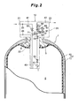
- a gas container 1 includes a container body 2 having a hermetically-sealed cylindrical shape as a whole, and a mouthpiece 3 attached to one end portion or opposite end portions of the container body 2 in a longitudinal direction.
- the inside of the container body 2 constitutes a storage space 5 in which various gases are stored.
- the gas container 1 may be filled with gas at normal pressure or gas having a pressure raised as compared with the normal pressure. That is, the gas container 1 of the present invention can function as a high-pressure gas container.
- a pressure of a combustible fuel gas prepared under a high pressure is reduced for use in power generation of a fuel cell.
- the gas container 1 of the present invention is applicable to storage of the high-pressure fuel gas, and a fuel gas such as a hydrogen gas or a compressed natural gas (the CNG gas) may be stored in the container.
- a pressure of hydrogen with which the gas container 1 is filled is, for example, 35 MPa or 70 MPa, and a pressure of the CNG gas is, for example, 20 MPa.
- the container body 2 is constituted of a double layer structure including an inner liner 6 (an inner shell) having a gas barrier property and a shell 7 (an outer shell) made of FRP with which the inner liner 6 is covered.
- the liner 6 is made of a resin such as highly dense polyethylene or a metal such as an aluminum alloy.
- the mouthpiece 3 is made of a metal such as stainless steel, and disposed at the center of an end wall portion of the container body 2 having a semispherical shape.
- An internal thread 9 is formed at an inner peripheral surface of an opening of the mouthpiece 3, and a valve assembly 10 is screwed into and connected to the internal thread.
- the valve assembly 10 is a module in which, in addition to a gas passage, piping line elements such as valves and joints, various gas sensors and the like are integrally incorporated in a housing 31.
- the valve assembly 10 connects an external gas filling line 21 to the storage space 5, and also connects an external gas discharge line 22 to the storage space 5.
- the storage space 5 is filled with, for example, a high-pressure hydrogen gas via the gas filling line 21 and the valve assembly 10.
- the hydrogen gas stored in the storage space 5 is discharged from the gas container 1 of the fuel cell system to the gas discharge line 22 via the valve assembly 10.
- the hydrogen gas is supplied to a fuel cell disposed at the gas discharge line 22.
- the gas container 1 is applied to a high-pressure hydrogen tank for the fuel cell will hereinafter be described.
- the valve assembly 10 is disposed so as to communicate with the inside and the outside of the gas container 1.
- the valve assembly 10 has the housing 31 (the valve body) provided with various valves (46, 51, 52, 62, 63, 64 and 74) and various gas passages (41 to 44).
- An external thread 32 to be screwed into the internal thread 9 of the mouthpiece 3 is formed at an outer peripheral surface of a neck portion of the housing 31, and the valve assembly 10 can be screwed into and connected to the mouthpiece 3 via this thread portion.
- a gap between the screwed and connected housing 31 and mouthpiece 3 is air-tightly sealed with a plurality of seal members (not shown).
- the housing 31 has, as passages which allow the inside of the gas container 1 to communicate with the outside, the filling passage 41 which allows the storage space 5 to communicate with the gas filling line 21, the discharge passage 42 which allows the storage space 5 to communicate with the gas discharge line 22, and the relief passage 43 disposed independently of the filling passage 41 and the discharge passage 42.
- the housing 31 also has a communication path 44 which connects the filling passage 41 to the discharge passage 42.
- the relief passage 43 opens to the outside at a head portion of the housing 31, and the other end of the relief passage opens in the storage space 5.
- the relief passage 43 is provided with a relief valve 46 which operates to open when the gas stored in the gas container 1 reaches a predetermined pressure or more.
- the relief valve 46 operates when the pressure of the gas stored in the gas container 1 reaches a minimum operation pressure (the predetermined pressure), and is constituted of, for example, a spring (mechanical) type valve. According to such a constitution, when the inside of the storage space 5 reaches an abnormally high pressure, the relief valve 46 opens. Therefore, the gas stored in the storage space 5 can be discharged from the relief passage 43, and damages on the gas container 1 can be avoided. It is to be noted that the relief valve 46 may be a fusible plug valve which fuses so as to allow the relief passage 43 to communicate with the outside (the atmosphere) at a high temperature (when a predetermined temperature is reached).
- the filling passage 41 is provided with a check valve 51 which inhibits counter flow of the gas and a manual valve 52 arranged in series with the check valve 51.
- check valve 51 and manual valve 52 constitute "a filling-side valve” or "a first valve” mentioned in the present invention.
- the discharge passage 42 is connected to the gas discharge line 22 (or the fuel cell on a downstream side of the line), and the other end of the passage opens in the storage space 5.
- the discharge passage 42 is provided with, in order from a storage space 5 side, a filter 61 which traps foreign matters in the gas, the shut-off valve 62 capable of electrically opening or closing the discharge passage 42, a manual valve 63 capable of opening or closing the discharge passage 42 by a manual operation, and a pressure regulation valve 64 which reduces the pressure of the gas to regulate the pressure.
- These shut-off valve 62 and manual valve 63 constitute "discharge-side valves" mentioned in the present invention.
- the downstream side of the filling passage 41 is a downstream side as viewed from a gas flow direction in the filling passage 41, in a case where the storage space 5 is filled with the gas from the gas filling line 21. Therefore, the check valve 51 is positioned on an upstream side (a primary side) of the manual valve 52.
- the downstream side of the filling passage as viewed from the check valve 51 corresponds to the inside of the gas container 1
- the upstream side of the filling passage corresponds to the outside of the gas container 1.
- the downstream side of the discharge passage 42 is a downstream side as viewed from a gas flow direction in the discharge passage 42, in a case where the gas is discharged from the storage space 5 to the gas discharge line 22. Therefore, the discharge passage 42 is provided with, in order from the upstream side of the passage, the filter 61, the shut-off valve 62, the manual valve 63 and the pressure regulation valve 64.
- the upstream side of the discharge passage as viewed from the shut-off valve 62 corresponds to the inside of the gas container 1
- the upstream side of the discharge passage corresponds to the outside of the gas container 1.
- the check valve 51 allows the gas to flow through the filling passage 41 on the downstream side, in a case where the gas is supplied from the gas filling line 21 to the filling passage 41.
- the check valve 51 shuts off the filling passage 41 owing to a pressure of the gas which is to flow from the gas container 1 to the upstream side of the filling passage 41. In consequence, the counter flow of the gas is inhibited.
- the manual valve 52 is positioned on the downstream side of the check valve 51, and an operating portion of the manual valve to be manually operated by a user is positioned outside the container body 2. It is to be noted that, as shown in a circuit diagram, this operating portion is actually positioned so as to protrude from an outer wall surface of the housing 31. When the user operates the operating portion to close the manual valve 52, the filling passage 41 is shut off. It is to be noted that, instead of the manual valve 52, an electrically driven valve such as an electromagnetic valve may be disposed. The manual valve 52 may be omitted.
- the filter 61 includes a filter element having a filtering degree in accordance with sizes of foreign matters as targets in the gas.
- the foreign matters include contamination and an oil content in addition to dust. Since the foreign matters can be removed from the gas by the filter 61, a clean gas can be discharged to the gas discharge line 22. Since the filter 61 is disposed on the most upstream side of the discharge passage 42, attachment of the foreign matters to valve bodies and valve seats of the shut-off valve 62, the manual valve 63 and the pressure regulation valve 64 on the downstream side of the filter is prevented.
- the shut-off valve 62 functions as a source valve of the gas container 1, and is positioned, for example, in the container body 2.
- the shut-off valve 62 is connected to a control device (not shown), and controlled to open and close in response to an output signal from the control device.
- This type of shut-off valve 62 is constituted of an electrically driven valve such as an electromagnetic valve to be driven by a solenoid, an electromotive valve to be driven by a motor or a valve to be driven by an electric or magnetic force of a piezoelectric element, a magnetostrictive element or the like.
- the shut-off valve 62 constituted of the electromagnetic valve includes a solenoid as a driving source, a valve rod driven by the solenoid to move forwards and backwards, and the valve seat with respect to which the valve rod comes close or away, although any of these components is not shown. Moreover, when the valve rod is energized by the solenoid and allowed to abut on the valve seat, the discharge passage 42 is shut off. On the other hand, when the valve rod comes away from the valve seat owing to demagnetization of the solenoid, the discharge passage 42 is allowed to communicate.
- An operating portion of the manual valve 63 to be manually operated by the user is positioned outside the container body 2. It is to be noted that, as shown in the circuit drawing, this operating portion is actually positioned so as to protrude from the outer wall surface of the housing 31. When the user operates the operating portion to close the manual valve 63, the discharge passage 42 is shut off. It is to be noted that, instead of the manual valve 63, an electrically driven valve such as the electromagnetic valve may be used. Alternatively, the manual valve 63 may be omitted.
- the pressure regulation valve 64 reduces the pressure of the gas flowing through the discharge passage 42 to a predetermined pressure.
- the pressure regulation valve 64 may be constituted by an operation system of a direct driving type or a pilot type.
- the pressure regulation valve 64 may be configured to control the pressure in a mechanical system or constituted as, for example, an electropneumatic regulator.
- the pressure regulation valve 64 is positioned outside the container body 2, and an operating portion for regulating an open valve characteristic of the pressure regulation valve is positioned so as to protrude from the outer wall surface of the housing 31. Therefore, the open valve characteristic of the pressure regulation valve 64 can be regulated with a satisfactory operability.
- One end of the communication path 44 is connected to the downstream side of the manual valve 52 in the filling passage 41 (or the downstream side as viewed from the check valve 51), and the other end of the communication path is connected to the downstream side of the shut-off valve 62 in the discharge passage 42 (or the downstream side as viewed from the manual valve 63) which is the upstream side of the pressure regulation valve 64. That is, a connection combining point 71 between the communication path 44 and the filling passage 41 is disposed on the downstream side of the manual valve 52, and a connection combining point 72 between the communication path 44 and the discharge passage 42 is disposed between the shut-off valve 62 and the pressure regulation valve 64.
- the communication path 44 is provided with a shut-off valve 74 capable of opening and closing this communication path.
- the shut-off valve 74 (a communication shut-off mechanism) may be constituted of an electrically driven valve in the same manner as in the shut-off valve 62 in the discharge passage 42, or may be constituted in the same manner as in the manual valve 63 in the discharge passage 42.
- the shut-off valve 74 of the present embodiment is constituted of a manual valve, and has a manual operating portion 150 for operating and closing the communication path 44 by a manual operation.
- the manual operating portion 150 is connected to a valve body 151. When the manual operating portion 150 is operated, the valve body 151 comes away from or comes in contact with a valve seat 152.
- This type of manual operating portion 150 may be constituted of a lever, a button of a push-pull operation system, or a circular handle to be rotatably operated.
- the manual operating portion 150 is positioned outside the container body 2, and disposed so as to protrude from an outer wall surface 31 a of the housing 31. Therefore, the user can easily access the manual operating portion 150 without detaching the valve assembly 10 from the mouthpiece 3.
- the filling passage 41 is allowed to communicate with the discharge passage 42.
- the shut-off valve 74 is closed, the filling passage 41 is allowed to communicate with the discharge passage 42.
- the shut-off valve 74 constantly closes, and is opened mainly during a failure of the shut-off valve 62 or the like.
- a valve having any function is applicable to the shut-off valve 74.
- Examples of a type of the shut-off valve 74 include a gate valve, a globe valve, a butterfly valve and a ball valve.
- the shut-off valve 74 may be constituted of the globe valve of an angle valve type or a Y-shaped valve type.
- valve assembly 10 of the present embodiment will be described.
- the manual valve 52 is opened and thereby the gas is introduced into the storage space 5 from the gas filling line 21 via the filling passage 41.
- the shut-off valve 74 disposed at the communication path 44 is closed, and the gas flowing through the filling passage 41 does not flow into the discharge passage 42 via the communication path 44.
- the manual valve 52 is closed. It is to be noted that the filling passage 41 is provided with the check valve 51. Therefore, even if the manual valve 52 is not closed after the completion of the filling with the gas, the gas can be inhibited from being discharged from the filling passage 41.
- the shut-off valve 62 and the manual valve 63 are opened.
- the shut-off valve 62 is opened, when electrically controlled by the control device (not shown), based on a request for the power generation in, for example, the fuel cell system.
- the manual valve 63 may be opened in advance before the gas is discharged.
- the shut-off valve 62 and the manual valve 63 are opened, the gas stored in the storage space 5 flows through the discharge passage 42, the pressure of the gas is reduced by the pressure regulation valve 64 and the gas is discharged to the gas discharge line 22.
- the shut-off valve 74 disposed at the communication path 44 is closed, and the gas flowing through the discharge passage 42 does not flow into the filling passage 41 via the communication path 44.
- shut-off valve 62 sticks and does not open, or a control circuit is disconnected and the shut-off valve 62 is not opened.
- the shut-off valve 62 does not open owing to such a failure or the like in some case.
- the valve assembly 10 needs to be detached from the mouthpiece 3 in order to inspect or replace the shut-off valve 62. If the gas container 1 remains to be filled with the gas, this detaching operation becomes laborious. Therefore, the gas needs to be discharged from the gas container 1.
- the shut-off valve 62 since the shut-off valve 62 does not open owing to the failure or the like, the gas cannot be discharged to the downstream side of the discharge passage 42 through the filter 61 and the shut-off valve 62 of the discharge passage 42.
- the shut-off valve 74 on the communication path 44 is opened, and the filling passage 41 is allowed to communicate with the discharge passage 42 in order to discharge the gas from the discharge passage 42.
- the gas stored in the storage space 5 flows through the filling passage 41 to flow into the communication path 44, and flow into the downstream side of the discharge passage 42 from the communication path 44.
- the gas can appropriately be discharged from the gas container 1 via the discharge passage 42 by effectively using the filling passage 41.
- the gas flowing through the discharge passage 42 passes through the pressure regulation valve 64. Therefore, the pressure of the gas is reduced, and the gas can be discharged from the gas container 1.
- this gas discharged during the failure maybe used in, for example, the power generation of the fuel cell of the fuel cell system.
- concentration of the gas discharged during the failure is reduced with a diluting gas (air or an inactive gas), the gas may be discharged to the atmosphere. Alternatively, the concentration may be reduced by an oxidation reaction on a catalyst.
- the shut-off valve 62 sticks and does not close, or the control circuit is disconnected and cannot close the shut-off valve 62. In this manner, the shut-off valve 62 does not close owing to the failure or the like in some case. In such a case, when the manual valve 63 on the downstream side of the shut-off valve 62 is closed, the gas can be inhibited from being discharged from the storage space 5 to the gas discharge line 22. However, needless to say, during occurrence of this disadvantage, the shut-off valve 74 disposed at the communication path 44 needs to be closed. When the pressure of the gas container 1 abnormally rises as described above, the relief valve 46 can be opened to discharge the gas from the gas container 1 via the relief passage 43, and damages on the gas container 1 can be avoided.
- the shut-off valve 74 is constituted of the manual valve, but an operation system of the valve may be changed, and the shut-off valve 74 may be constituted of, for example, a foot valve. That is, the shut-off valve 74 may be constituted of a man-powered valve such as the manual valve or the foot valve. This also applies to the manual valve 52 and the manual valve 63.
- a discharge passage 42 is provided with a pressure sensor 81 and a temperature sensor 91.
- the pressure sensor 81 is disposed on a downstream side of a connection combining point 72 between the discharge passage 42 and a communication path 44 which is an upstream side of a pressure regulation valve 64. Since the pressure sensor 81 is positioned on a primary side of the pressure regulation valve 64, the pressure sensor 81 can detect a pressure of the gas of a storage space 5.
- the pressure sensor 81 is attached to a passage 82 disposed so as to branch sideward from the discharge passage 42. An attaching portion between the pressure sensor 81 and the passage 82 is sealed with a seal member (not shown).
- the temperature sensor 91 is disposed on the downstream side of the connection combining point 72 between the discharge passage 42 and the communication path 44 which is the upstream side of the pressure regulation valve 64.
- the temperature sensor 91 can detect a temperature of the gas of the storage space 5.
- the temperature sensor 91 is attached to a passage 92 disposed so as to branch sideward from the discharge passage 42. An attaching portion between the temperature sensor 91 and the passage 92 is sealed with a seal member (not shown).
- an amount of the gas to fill a gas container 1 can be calculated by the pressure sensor 81 and the temperature sensor 91. If the gas leaks from the pressure sensor 81 or the attaching portion (the sealed portion) between the pressure sensor 81 and the passage 82, a shut-off valve 62 can be closed to inhibit the gas leakage. Similarly, if the gas leaks from the temperature sensor 91 or the attaching portion between the temperature sensor 91 and the passage 92, the shut-off valve 62 can be closed to inhibit the gas leakage. Therefore, a seal structure for the pressure sensor 81 and the temperature sensor 91 can be simplified.
- the pressure sensor 81 and the temperature sensor 91 may be disposed at any position on the downstream side of the shut-off valve 62, for example, on the upstream side of the connection combining point 72 between the discharge passage 42 and the communication path 44.
- One of the pressure sensor 81 and the temperature sensor 91 may be omitted.
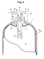
- valve assembly 10 according to a third embodiment will mainly be described with reference to FIG. 3 .
- the embodiment is different from the first embodiment in that a check valve 101 (a filling-side valve) is added to a filling passage 41.
- two check valves 51, 101 having a similar function are arranged in series at the filling passage 41. According to such a constitution, even if outflow of gas as a counter flow cannot be inhibited owing to a failure of one (51 or 101) of the check valves, the counter flow of the gas can be inhibited by the other check valve (101 or 51). It is to be noted that it is preferable to set a minimum operation pressure of the check valve 101 on a downstream side to be smaller than that of the check valve 51 on an upstream side.
- the filling passage 41 may be provided with two or more check valves.
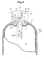
- a different respect of a valve assembly 10 according to a fourth embodiment will mainly be described with reference to FIG. 4 .
- the embodiment is different from the first embodiment in that a relief passage 43 is connected to a filling passage 41 so as to be branched from the passage.
- One end of the relief passage 43 opens to the outside of a housing 31, and the other end of the relief passage is connected to the filling passage 41.
- a branch connection point between the relief passage 43 and the filling passage 41 is positioned on a downstream side of a check valve 51.
- the embodiment is different from the first embodiment in that a relief passage 43 is connected to a discharge passage 42 via a communication path 44, and accordingly the filling passage 41 is disposed independently of the discharge passage 42.
- One end of the communication path 44 is connected to a portion on an upstream side from a relief valve 46 (a first valve), that is, a portion of the relief passage 43 on a storage space 5 side as viewed from the relief valve 46.
- the other end of the communication path 44 is connected to a downstream side of a shut-off valve 62 in the discharge passage 42 which is the upstream side of a pressure regulation valve 64 in the same manner as described above.
- the communication path 44 is provided with a shut-off valve 74 (a communication shut-off mechanism) capable of opening and closing this communication path in the same manner as described above.
- the shut-off valve 74 disposed at the communication path 44 can be opened to allow the relief passage 43 to communicate with the discharge passage 42.
- the gas stored in the storage space 5 flows through the relief passage 43 to flow into the communication path 44, and flows into the discharge passage 42 on the downstream side from the communication path 44.
- the gas can appropriately be discharged from a gas container 1 via the discharge passage 42 by effectively using the relief passage 43 as in the present embodiment.
- a communication shut-off mechanism may be constituted which is capable of shutting off and allowing the communication.
- the communication shut-off mechanism may be constituted of two shut-off valves (not shown) disposed on an upstream side and a downstream side of a connection combining point 71 in the filling passage 41, and two shut-off valves (not shown) disposed on an upstream side and a downstream side of a connection combining point 72 in the discharge passage 42.
- the above shut-off valve 62 is applicable to the shut-off valve on the upstream side of the connection combining point 72 in the discharge passage 42.
- shut-off valve assembly 10 When these four shut-off valves are appropriately opened or closed during discharging of a gas in a case where the shut-off valve 62 does not open in addition to filling with the gas and discharging of the gas, the above specification of the valve assembly 10 can be achieved.
- a gas container 1 including a valve assembly 10 is preferably used in a vehicle and the like on which a fuel cell system is mounted.
- the gas container 1 of the present invention is preferably applicable to transport facilities such as an airplane and a ship in which the gas container is used as a power source, in addition to the vehicle.
Landscapes
- Engineering & Computer Science (AREA)
- Mechanical Engineering (AREA)
- General Engineering & Computer Science (AREA)
- Filling Or Discharging Of Gas Storage Vessels (AREA)
Applications Claiming Priority (2)
| Application Number | Priority Date | Filing Date | Title |
|---|---|---|---|
| JP2005056071A JP4496477B2 (ja) | 2005-03-01 | 2005-03-01 | ガス容器用バルブアッセンブリ |
| PCT/JP2006/303516 WO2006093060A1 (ja) | 2005-03-01 | 2006-02-20 | ガス容器用バルブアッセンブリ |
Publications (3)
| Publication Number | Publication Date |
|---|---|
| EP1855048A1 EP1855048A1 (en) | 2007-11-14 |
| EP1855048A4 EP1855048A4 (en) | 2009-04-15 |
| EP1855048B1 true EP1855048B1 (en) | 2012-03-28 |
Family
ID=36941091
Family Applications (1)
| Application Number | Title | Priority Date | Filing Date |
|---|---|---|---|
| EP20060714655 Active EP1855048B1 (en) | 2005-03-01 | 2006-02-20 | Valve assembly for gas container |
Country Status (8)
| Country | Link |
|---|---|
| US (1) | US8573253B2 (enExample) |
| EP (1) | EP1855048B1 (enExample) |
| JP (1) | JP4496477B2 (enExample) |
| KR (1) | KR100903663B1 (enExample) |
| CN (1) | CN101133281B (enExample) |
| CA (1) | CA2598624C (enExample) |
| RU (1) | RU2355943C1 (enExample) |
| WO (1) | WO2006093060A1 (enExample) |
Cited By (1)
| Publication number | Priority date | Publication date | Assignee | Title |
|---|---|---|---|---|
| EP2728229A1 (de) | 2012-11-05 | 2014-05-07 | Magna Steyr Fahrzeugtechnik AG & Co KG | Drucksperrventileinheit für einen Druckspeicherbehälter |
Families Citing this family (57)
| Publication number | Priority date | Publication date | Assignee | Title |
|---|---|---|---|---|
| JP4714125B2 (ja) * | 2006-11-16 | 2011-06-29 | 本田技研工業株式会社 | ガス燃料用配管装置 |
| US8322569B2 (en) | 2007-12-06 | 2012-12-04 | L'air Liquide Societe Anonyme Pour L'etude Et L'exploitation Des Procedes Georges Claude | Integrated valve regulator assembly and system for the controlled storage and dispensing of a hazardous material |
| JP5239376B2 (ja) * | 2008-02-14 | 2013-07-17 | トヨタ自動車株式会社 | 燃料電池システム |
| FR2927979A1 (fr) * | 2008-02-21 | 2009-08-28 | Air Liquide | Dispositif de remplissage et de distribution de gaz et procede de remplissage. |
| US8104500B2 (en) * | 2008-04-18 | 2012-01-31 | Texas Institute Of Science, Inc. | Acoustic liquid level detection |
| FR2930619A1 (fr) * | 2008-04-24 | 2009-10-30 | Air Liquide | Dispositif receveur de gaz sous pression, ensemble distributeur-dispositif receveur et systeme d'alimentation correspondant |
| FR2931223B1 (fr) | 2008-05-16 | 2010-08-20 | Air Liquide | Dispositif distributeur de gaz sous pression, ensemble comprenant un tel dispositif et dispositif de commande, recipient pourvu d'un tel dispositif distributeur |
| JP5381104B2 (ja) * | 2009-01-05 | 2014-01-08 | トヨタ自動車株式会社 | ガス容器用バルブアッセンブリ |
| EP2389533B1 (en) * | 2009-01-26 | 2012-11-28 | Cavagna Group S.p.a. | A valve unit for pressure vessels |
| JP5409036B2 (ja) * | 2009-02-16 | 2014-02-05 | トヨタ自動車株式会社 | 車両用高圧タンクのバルブ装置 |
| JP2010245004A (ja) * | 2009-04-10 | 2010-10-28 | Honda Motor Co Ltd | 燃料充填供給システム |
| JP5386249B2 (ja) | 2009-07-03 | 2014-01-15 | トヨタ自動車株式会社 | 車両用高圧タンクのバルブ装置 |
| JP5333145B2 (ja) * | 2009-10-14 | 2013-11-06 | トヨタ自動車株式会社 | 車両用高圧タンクのバルブ装置 |
| JP5466033B2 (ja) * | 2010-02-15 | 2014-04-09 | トヨタ自動車株式会社 | 高圧タンクの圧抜き用バルブ |
| JP5115565B2 (ja) * | 2010-02-15 | 2013-01-09 | トヨタ自動車株式会社 | 車両 |
| JP2011179528A (ja) * | 2010-02-26 | 2011-09-15 | Kawasaki Heavy Ind Ltd | タンク内圧力計測用回路及びそれを備えるタンク装置 |
| FR2974883B1 (fr) * | 2011-05-04 | 2014-05-09 | Michelin Soc Tech | Vanne montee sur un reservoir contenant un gaz a haute pression |
| JP6007317B2 (ja) * | 2012-06-04 | 2016-10-12 | ヨンド・アイエヌデー・カンパニー・リミテッド | 流体制御用バルブアセンブリ |
| DE102012019908A1 (de) * | 2012-10-11 | 2014-04-17 | Linde Aktiengesellschaft | Verfahren und Einrichtung zur zumindest teilweisen Entgasung eines ein Fluid enthaltenden Gefäßes |
| EP2728228B1 (de) * | 2012-11-05 | 2015-06-17 | Magna Steyr Fahrzeugtechnik AG & Co KG | Sperrventil für einen Druckspeicherbehälter |
| CN104006285A (zh) * | 2013-02-22 | 2014-08-27 | 西门子公司 | 一种用于燃气轮机的排流系统 |
| US8910651B2 (en) * | 2013-03-13 | 2014-12-16 | GM Global Technology Operations LLC | Thermal pressure relief devices and related systems and methods |
| KR101497420B1 (ko) * | 2013-07-05 | 2015-03-03 | 삼성중공업 주식회사 | 증발가스 저감용 액화천연가스 수송장치 |
| US20150059895A1 (en) * | 2013-08-30 | 2015-03-05 | dHybrid Systems, LLC | Vehicle fueling manifold assembly |
| ITBS20130164A1 (it) * | 2013-11-13 | 2015-05-14 | Omb Saleri S P A | Valvola per metano in sistemi per autotrazione munita di dispositivo di sicurezza termica |
| DE102013019825B4 (de) | 2013-11-26 | 2025-01-23 | Cellcentric Gmbh & Co. Kg | Ventileinrichtung für einen Druckgasspeicher |
| NL2015258A (en) | 2014-08-03 | 2016-07-07 | Protochips Inc | Method for safe control of gas delivery to an electron microscope sample holder. |
| EP3324086B1 (en) * | 2015-07-15 | 2019-09-11 | Nissan Motor Co., Ltd. | Valve device |
| GB201520374D0 (en) * | 2015-11-19 | 2016-01-06 | Moog Controls Ltd | A method for releasing a fluid from a pressure vessel assembly |
| US10696155B2 (en) | 2016-04-01 | 2020-06-30 | Agility Fuel Systems Llc | Vehicle fluid handling systems |
| DE102016008107A1 (de) * | 2016-07-01 | 2018-01-04 | Daimler Ag | Tankventil |
| DE102017201045A1 (de) * | 2017-01-23 | 2018-07-26 | Bayerische Motoren Werke Aktiengesellschaft | Druckbehältersystem für ein Kraftfahrzeug |
| JP6878040B2 (ja) * | 2017-02-20 | 2021-05-26 | 株式会社Soken | 弁装置 |
| FR3067094B1 (fr) * | 2017-06-01 | 2020-08-14 | L'air Liquide Sa Pour L'etude Et L'exploitation Des Procedes Georges Claude | Robinet, stockage et station de remplissage |
| FR3067095B1 (fr) * | 2017-06-01 | 2020-08-14 | L'air Liquide Sa Pour L'etude Et L'exploitation Des Procedes Georges Claude | Robinet, stockage et station de remplissage |
| DE102017213521A1 (de) * | 2017-08-03 | 2019-02-07 | Bayerische Motoren Werke Aktiengesellschaft | Ventil-Vorrichtung für einen Speicherbehälter |
| DE102017213524A1 (de) * | 2017-08-03 | 2019-02-07 | Bayerische Motoren Werke Aktiengesellschaft | Ventil-Vorrichtung für einen Druckbehälter eines Druckbehältersystems mit mehreren Druckbehältern |
| JP6515982B1 (ja) * | 2017-11-22 | 2019-05-22 | 横浜ゴム株式会社 | 航空機用水タンクおよびその製造方法 |
| US11440399B2 (en) | 2019-03-22 | 2022-09-13 | Agility Fuel Systems Llc | Fuel system mountable to a vehicle frame |
| JP7257856B2 (ja) * | 2019-04-05 | 2023-04-14 | キヤノン株式会社 | 記録装置 |
| US20200347992A1 (en) | 2019-05-02 | 2020-11-05 | Agility Fuel Systems Llc | Polymeric liner based gas cylinder with reduced permeability |
| US20230049965A1 (en) * | 2019-06-10 | 2023-02-16 | Patched Conics, LLC. | Fluid supply device |
| TWI706103B (zh) * | 2019-08-05 | 2020-10-01 | 古豐愿 | 負壓供氣鋼瓶 |
| DE102019212037A1 (de) * | 2019-08-12 | 2021-02-18 | Robert Bosch Gmbh | System zur Druckentlastung eines Druckbehälters |
| CN112555679B (zh) * | 2019-09-26 | 2022-02-25 | 未势能源科技有限公司 | 压力容器和车辆 |
| DE102019128427A1 (de) * | 2019-10-22 | 2021-04-22 | Audi Ag | Ventileinrichtung und Gasdruckspeicher |
| KR20220102655A (ko) * | 2019-12-02 | 2022-07-20 | 플라스틱 옴니엄 뉴 에너지스 프랑스 | 차량용 가압 유체 저장 및 분배 조립체 |
| DE202021004175U1 (de) * | 2020-04-24 | 2022-12-19 | Youon Technology Co., Ltd. | Wasserstoffspeicher und Wasserstoffspeichersystem |
| DE102020207253A1 (de) * | 2020-06-10 | 2021-12-16 | Argo Gmbh | Ventileinrichtung, Intankventil und Gasdruckspeichersystem, insbesondere für Brennstoffzellensysteme, sowie Verfahren zum Detektieren einer Leckage |
| JP7539263B2 (ja) | 2020-06-25 | 2024-08-23 | 川崎重工業株式会社 | ガス用ケーシング、及びタンクバルブ装置 |
| CN113970001A (zh) * | 2020-07-25 | 2022-01-25 | 浙江三花汽车零部件有限公司 | 集成组件 |
| JP2024128860A (ja) * | 2023-03-10 | 2024-09-24 | 川崎重工業株式会社 | ノズルヘッド、及びそれを備えるタンクバルブ装置 |
| KR102837562B1 (ko) * | 2023-03-31 | 2025-07-23 | 영도산업 주식회사 | 유체 제어용 밸브 어셈블리 |
| DE102023204902A1 (de) * | 2023-05-25 | 2024-11-28 | Robert Bosch Gesellschaft mit beschränkter Haftung | Tankventilanordnung und Verfahren zum Betanken eines Gasdruckspeichers |
| DE102023207276A1 (de) * | 2023-07-31 | 2025-02-06 | Robert Bosch Gesellschaft mit beschränkter Haftung | Verfahren zum Betreiben einer Druckgasspeichervorrichtung mit mindestens einem Druckgasbehälter, Druckgasbehälter sowie Druckgasspeichervorrichtung |
| DE102023213009A1 (de) * | 2023-12-20 | 2025-06-26 | Robert Bosch Gesellschaft mit beschränkter Haftung | Betankungsverfahren und Tanksystem |
| CN118582652B (zh) * | 2024-07-19 | 2025-10-14 | 广东省洛仑兹技术股份有限公司 | 一种储氢容器及氢动力车辆 |
Family Cites Families (21)
| Publication number | Priority date | Publication date | Assignee | Title |
|---|---|---|---|---|
| US3307597A (en) * | 1964-09-16 | 1967-03-07 | Voit Rubber Corp | First stage pressure regulators mounted within air cylinder plug |
| US4006205A (en) * | 1975-03-17 | 1977-02-01 | Etter Berwyn E | Means for applying additives to industrial gas |
| SU1201610A1 (ru) * | 1984-07-06 | 1985-12-30 | Предприятие П/Я А-3681 | Система газозар дки |
| US4583372A (en) * | 1985-01-30 | 1986-04-22 | At&T Technologies, Inc. | Methods of and apparatus for storing and delivering a fluid |
| US5193580A (en) | 1991-05-30 | 1993-03-16 | Wass Lloyd G | Crash proof solenoid controlled valve with manual override valve |
| US5197710A (en) | 1991-05-30 | 1993-03-30 | Lloyd G. Wass | Crash proof solenoid controlled valve for natural gas powered vehicles |
| DE69300301T2 (de) * | 1992-09-09 | 1996-04-04 | Neriki Kk | Ventilanordnung für Gasbehälter. |
| JP3120316B2 (ja) * | 1994-06-24 | 2000-12-25 | 株式会社ネリキ | ガスボンベ用バルブ装置 |
| AU691270B2 (en) * | 1994-06-24 | 1998-05-14 | Kabushiki Kaisha Neriki | Valve assembly for gas cylinder |
| US6041762A (en) | 1996-08-16 | 2000-03-28 | Impco Technologies, Inc. | Control module for natural gas fuel supply for a vehicle |
| JP2943980B2 (ja) | 1997-07-24 | 1999-08-30 | 本田技研工業株式会社 | ガス燃料用配管装置 |
| US7013916B1 (en) * | 1997-11-14 | 2006-03-21 | Air Products And Chemicals, Inc. | Sub-atmospheric gas delivery method and apparatus |
| GB9724168D0 (en) * | 1997-11-14 | 1998-01-14 | Air Prod & Chem | Gas control device and method of supplying gas |
| RU2153622C1 (ru) * | 1999-04-05 | 2000-07-27 | Открытое акционерное общество "Ракетно-космическая корпорация "Энергия" им. С.П. Королева" | Устройство для хранения и подачи криогенных продуктов |
| US6766829B2 (en) * | 2000-02-18 | 2004-07-27 | Kabushiki Kaisha Neriki | Valve assembly for gas cylinder |
| CA2312186A1 (en) | 2000-06-23 | 2001-12-23 | Erick Girouard | Crashproof instant-on tank valve |
| JP2002115798A (ja) * | 2000-10-06 | 2002-04-19 | Neriki:Kk | バルブ装置 |
| JP4774634B2 (ja) | 2001-06-15 | 2011-09-14 | トヨタ自動車株式会社 | 気体貯蔵システム |
| JP2003166700A (ja) * | 2001-11-30 | 2003-06-13 | Nippon Sanso Corp | 減圧機能付き容器弁 |
| FR2833861B1 (fr) * | 2001-12-20 | 2004-02-06 | Air Liquide | Dispositif de stockage et de melange de deux gaz |
| JP4736312B2 (ja) * | 2003-07-31 | 2011-07-27 | トヨタ自動車株式会社 | タンク |
-
2005
- 2005-03-01 JP JP2005056071A patent/JP4496477B2/ja not_active Expired - Lifetime
-
2006
- 2006-02-20 RU RU2007135747A patent/RU2355943C1/ru not_active IP Right Cessation
- 2006-02-20 US US11/884,129 patent/US8573253B2/en active Active
- 2006-02-20 WO PCT/JP2006/303516 patent/WO2006093060A1/ja not_active Ceased
- 2006-02-20 EP EP20060714655 patent/EP1855048B1/en active Active
- 2006-02-20 CN CN2006800069759A patent/CN101133281B/zh active Active
- 2006-02-20 KR KR1020077020048A patent/KR100903663B1/ko not_active Expired - Fee Related
- 2006-02-20 CA CA 2598624 patent/CA2598624C/en active Active
Cited By (3)
| Publication number | Priority date | Publication date | Assignee | Title |
|---|---|---|---|---|
| EP2728229A1 (de) | 2012-11-05 | 2014-05-07 | Magna Steyr Fahrzeugtechnik AG & Co KG | Drucksperrventileinheit für einen Druckspeicherbehälter |
| US9081391B2 (en) | 2012-11-05 | 2015-07-14 | Magna Steyr Fahrzeugtechnik Ag & Co Kg | Valve assembly for pressure storage vessel |
| EP2927549A1 (de) | 2012-11-05 | 2015-10-07 | Magna Steyr Fahrzeugtechnik AG & Co KG | Drucksperrventileinheit für einen druckspeicherbehälter |
Also Published As
| Publication number | Publication date |
|---|---|
| WO2006093060A1 (ja) | 2006-09-08 |
| CN101133281A (zh) | 2008-02-27 |
| CA2598624C (en) | 2010-06-08 |
| KR100903663B1 (ko) | 2009-06-18 |
| EP1855048A4 (en) | 2009-04-15 |
| JP4496477B2 (ja) | 2010-07-07 |
| CA2598624A1 (en) | 2006-09-08 |
| RU2355943C1 (ru) | 2009-05-20 |
| US20080105310A1 (en) | 2008-05-08 |
| EP1855048A1 (en) | 2007-11-14 |
| US8573253B2 (en) | 2013-11-05 |
| JP2006242225A (ja) | 2006-09-14 |
| CN101133281B (zh) | 2010-04-21 |
| KR20070099687A (ko) | 2007-10-09 |
Similar Documents
| Publication | Publication Date | Title |
|---|---|---|
| EP1855048B1 (en) | Valve assembly for gas container | |
| US6691729B2 (en) | Valve assembly | |
| EP3309433B1 (en) | Safe valve for high pressure regulator | |
| US6901952B2 (en) | Gas flow regulation system | |
| CN101189470B (zh) | 高压罐 | |
| CA2617999C (en) | Tank manifold assembly | |
| US5992219A (en) | Gas fuel supply piping system | |
| US8020430B2 (en) | Passive leak detection devices and systems for detecting gas leaks | |
| WO2007102297A1 (ja) | バルブ、バルブ制御装置及び燃料電池システム | |
| JP5381104B2 (ja) | ガス容器用バルブアッセンブリ | |
| JP6650427B2 (ja) | インタンクレギュレーターの圧力測定システム | |
| US20100206402A1 (en) | Valve device of high-pressure tank for vehicle | |
| CN120332660A (zh) | 瓶口组合阀、储氢瓶组及车载供氢系统 | |
| CN120187980A (zh) | 阀装置、罐、燃料电池系统及氢燃烧发动机系统 | |
| JP2006052787A (ja) | 容器バルブ | |
| JP2006057773A (ja) | ガス供給システム |
Legal Events
| Date | Code | Title | Description |
|---|---|---|---|
| PUAI | Public reference made under article 153(3) epc to a published international application that has entered the european phase |
Free format text: ORIGINAL CODE: 0009012 |
|
| 17P | Request for examination filed |
Effective date: 20070823 |
|
| AK | Designated contracting states |
Kind code of ref document: A1 Designated state(s): DE FR GB IT |
|
| DAX | Request for extension of the european patent (deleted) | ||
| RBV | Designated contracting states (corrected) |
Designated state(s): DE FR GB IT |
|
| A4 | Supplementary search report drawn up and despatched |
Effective date: 20090313 |
|
| 17Q | First examination report despatched |
Effective date: 20090708 |
|
| GRAP | Despatch of communication of intention to grant a patent |
Free format text: ORIGINAL CODE: EPIDOSNIGR1 |
|
| GRAS | Grant fee paid |
Free format text: ORIGINAL CODE: EPIDOSNIGR3 |
|
| RIN1 | Information on inventor provided before grant (corrected) |
Inventor name: KOBAYASHI, NOBUOC/O TOYOTA JIDOSHA KABUSHIKI KAISH Inventor name: OGAMI, NOBUYUKIC/O TOYOTA JIDOSHA KABUSHIKI KAISHA Inventor name: YAMASHITA, AKIRAC/O TOYOTA JIDOSHA KABUSHIKI KAISH |
|
| GRAA | (expected) grant |
Free format text: ORIGINAL CODE: 0009210 |
|
| AK | Designated contracting states |
Kind code of ref document: B1 Designated state(s): DE FR GB IT |
|
| REG | Reference to a national code |
Ref country code: GB Ref legal event code: FG4D |
|
| REG | Reference to a national code |
Ref country code: DE Ref legal event code: R096 Ref document number: 602006028447 Country of ref document: DE Effective date: 20120524 |
|
| REG | Reference to a national code |
Ref country code: GB Ref legal event code: 746 Effective date: 20121112 |
|
| REG | Reference to a national code |
Ref country code: DE Ref legal event code: R084 Ref document number: 602006028447 Country of ref document: DE Effective date: 20121115 |
|
| PLBE | No opposition filed within time limit |
Free format text: ORIGINAL CODE: 0009261 |
|
| STAA | Information on the status of an ep patent application or granted ep patent |
Free format text: STATUS: NO OPPOSITION FILED WITHIN TIME LIMIT |
|
| RAP2 | Party data changed (patent owner data changed or rights of a patent transferred) |
Owner name: TOYOTA JIDOSHA KABUSHIKI KAISHA |
|
| 26N | No opposition filed |
Effective date: 20130103 |
|
| REG | Reference to a national code |
Ref country code: DE Ref legal event code: R097 Ref document number: 602006028447 Country of ref document: DE Effective date: 20130103 |
|
| REG | Reference to a national code |
Ref country code: FR Ref legal event code: PLFP Year of fee payment: 11 |
|
| REG | Reference to a national code |
Ref country code: FR Ref legal event code: PLFP Year of fee payment: 12 |
|
| PGFP | Annual fee paid to national office [announced via postgrant information from national office to epo] |
Ref country code: FR Payment date: 20170112 Year of fee payment: 12 |
|
| PGFP | Annual fee paid to national office [announced via postgrant information from national office to epo] |
Ref country code: GB Payment date: 20170215 Year of fee payment: 12 |
|
| PGFP | Annual fee paid to national office [announced via postgrant information from national office to epo] |
Ref country code: IT Payment date: 20170221 Year of fee payment: 12 |
|
| GBPC | Gb: european patent ceased through non-payment of renewal fee |
Effective date: 20180220 |
|
| REG | Reference to a national code |
Ref country code: FR Ref legal event code: ST Effective date: 20181031 |
|
| PG25 | Lapsed in a contracting state [announced via postgrant information from national office to epo] |
Ref country code: GB Free format text: LAPSE BECAUSE OF NON-PAYMENT OF DUE FEES Effective date: 20180220 Ref country code: IT Free format text: LAPSE BECAUSE OF NON-PAYMENT OF DUE FEES Effective date: 20180220 Ref country code: FR Free format text: LAPSE BECAUSE OF NON-PAYMENT OF DUE FEES Effective date: 20180228 |
|
| P01 | Opt-out of the competence of the unified patent court (upc) registered |
Effective date: 20230427 |
|
| PGFP | Annual fee paid to national office [announced via postgrant information from national office to epo] |
Ref country code: DE Payment date: 20241231 Year of fee payment: 20 |