EP1854704A1 - Joints et système et procédure de formation de joints - Google Patents
Joints et système et procédure de formation de joints Download PDFInfo
- Publication number
- EP1854704A1 EP1854704A1 EP07009213A EP07009213A EP1854704A1 EP 1854704 A1 EP1854704 A1 EP 1854704A1 EP 07009213 A EP07009213 A EP 07009213A EP 07009213 A EP07009213 A EP 07009213A EP 1854704 A1 EP1854704 A1 EP 1854704A1
- Authority
- EP
- European Patent Office
- Prior art keywords
- connector
- distal end
- tubular structure
- members
- joint
- Prior art date
- Legal status (The legal status is an assumption and is not a legal conclusion. Google has not performed a legal analysis and makes no representation as to the accuracy of the status listed.)
- Withdrawn
Links
Images


Classifications
-
- B—PERFORMING OPERATIONS; TRANSPORTING
- B62—LAND VEHICLES FOR TRAVELLING OTHERWISE THAN ON RAILS
- B62D—MOTOR VEHICLES; TRAILERS
- B62D23/00—Combined superstructure and frame, i.e. monocoque constructions
- B62D23/005—Combined superstructure and frame, i.e. monocoque constructions with integrated chassis in the whole shell, e.g. meshwork, tubes, or the like
-
- B—PERFORMING OPERATIONS; TRANSPORTING
- B62—LAND VEHICLES FOR TRAVELLING OTHERWISE THAN ON RAILS
- B62D—MOTOR VEHICLES; TRAILERS
- B62D27/00—Connections between superstructure or understructure sub-units
- B62D27/02—Connections between superstructure or understructure sub-units rigid
- B62D27/023—Assembly of structural joints
-
- B—PERFORMING OPERATIONS; TRANSPORTING
- B62—LAND VEHICLES FOR TRAVELLING OTHERWISE THAN ON RAILS
- B62D—MOTOR VEHICLES; TRAILERS
- B62D27/00—Connections between superstructure or understructure sub-units
- B62D27/02—Connections between superstructure or understructure sub-units rigid
- B62D27/026—Connections by glue bonding
-
- B—PERFORMING OPERATIONS; TRANSPORTING
- B62—LAND VEHICLES FOR TRAVELLING OTHERWISE THAN ON RAILS
- B62D—MOTOR VEHICLES; TRAILERS
- B62D29/00—Superstructures, understructures, or sub-units thereof, characterised by the material thereof
- B62D29/001—Superstructures, understructures, or sub-units thereof, characterised by the material thereof characterised by combining metal and synthetic material
- B62D29/002—Superstructures, understructures, or sub-units thereof, characterised by the material thereof characterised by combining metal and synthetic material a foamable synthetic material or metal being added in situ
Definitions
- the present invention relates generally to the formation of joints of articles of manufacture such as a transportation vehicle and, more particularly, the present invention relates to the formation of joints interconnecting at least one tubular frame member of an automotive vehicle with at least one other member of the vehicle.
- the present invention provides a joint and a system and method of forming the joint wherein the joint, the system and/or the method address one or more the aforementioned issues or other issues arising out of the new manufacturing trends.
- the present invention is directed to a joint and method of forming the joint.
- a first member and second member each having a distal end are provided.
- the first member, the second member or both can be provided by hydroforming a tubular structure defined by the respective member.
- a connector is also provided according to the method.
- the connector typically includes a base portion, a first portion extending away from the base portion and a second portion extending away from the base portion.
- the connector also typically includes an activatable material disposed upon the first portion and the second portion. The first portion and second portion are typically located adjacent the distal ends of the first member and second member.
- the first portion is typically located within the tunnel of the first tubular structure at the distal end of the first member and the second portion is typically located within the tunnel of the second tubular structure adjacent the distal end of the second member.
- the activatable material is typically activated to form a structural adhesive foam adhered to the first portion of the connector and the distal end of the first member and adhered to the second portion of the connector and the distal end of the second member.
- the activatable material can adhere to the interior surface of the first tubular and the interior surface of the second tubular structure.
- the first member is free of direct contact with the second member upon formation of the joint.
- the present invention provides a joint for an article of manufacture.
- the present invention also provides a system and method for the formation of the joint. It is contemplated, and in certain circumstances, for a single article of manufacture to include multiple (e.g., 2, 3, 4, 5, 6 or more) joints formed in accordance with the present invention.
- the joint of the present invention is particularly useful for automotive vehicles although it is contemplated that the joint may be applied to a variety of articles of manufacture such as airplanes, boats, buildings, furniture or the like.
- a joint formed in accordance with the present invention will typically includes two or more of the following:
- the first member is without direct contact with the second member, although such is not required unless specifically stated.
- the connector of the present invention will typically include a base portion and one, two, three, four or more connective portions extending away from the base portion. It is generally preferable that the connector be a monolithic structure formed of a singular material although it is contemplated that the connector be formed of multiple pieces.
- the connector is internally solid and continuous. Examples of such connectors are shown in Figs. 1A and 1B. As an alternative, however, the connector can be skeletal in nature. A skeletal connector will typically include multiple ribs extending in one, two, three or more directions. In one preferred embodiment, the connector can include one or a plurality of first ribs that intersect one or a plurality of second ribs. Examples of such connectors are shown in Figs. 2A and 2B.
- the connector can be formed of a variety of materials and can be formed of a single material or multiple materials.
- the connector may be formed of polymeric materials, metals (e.g., aluminum, steel, magnesium, metal alloys) combinations thereof or the like.
- polymeric materials e.g., thermoplastics, rubber, elastomer, thermosets or the like
- examples of polymeric materials include, without limitation, polyester, polypropylene, polyamide, molding compounds (e.g., sheet or bulk molding compound), polyethylene, polyvinylchloride, polyethylene, combinations thereof or the like.
- the technique for forming and shaping the connector will typically depend upon the material of the connector. Examples of techniques include, without limitation, molding, stamping, hydroforming or the like.
- the connector could be a metal stamping, a metal casting (e.g., a metal, aluminum, aluminum foam, magnesium or magnesium foam casting), a thixomolded structure.
- the connector could also be a molded (e.g., injection, compression or blow molded) plastic structure.
- a joint according to the present invention can connect two members, three members, four members or more.
- the members can have a variety of configurations.
- each member of the invention has a distal end adjacent a portion of the connector and the member is elongated and extends outwardly away from the connector.
- the members will typically be formed of a metal material, however, it is also contemplated that the member can be formed of polymeric materials such as plastics (e.g., thermoset or thermpoplastic material) or composite laminates.
- Exemplary metal materials include, without limitation, steel, titanium, aluminum, iron, metal alloys, combinations thereof or the like.
- the present invention is generally desirable for joining hollow members together.
- a hollow member is one that includes or defines an opening.
- the present invention is particularly desirable for joining tubular members.
- a tubular member is one that defines and substantially or entirely surrounds an opening and more particularly a tunnel.
- the tubular members or other shaped members can be hydroformed tubes, press formed tubes, roll formed tubes, stampings, thixomolds, extrusions (e.g., aluminum extrusions), castings, molded members (e.g., injection, compression or blow molded).
- the present invention contemplates method of forming joints that include prior or simultaneous forming and/or shaping of the members using one or any combination of the following techniques: hydroforming, casting, roll forming, stamping, thixomolding, injection molding, compression molding or blow molding.
- the adhesive material may be an expandable or foamable material that is activated to expand and then cure to form a strong bond between adjacent surfaces (e.g. attachment surfaces).
- the adhesion material When expandable, the adhesion material preferably undergoes a volumetric expansion of no greater than 500%, more preferably no greater than 100% and even more preferably no greater than 50% over its original non-expanded volume. Of course, higher expansion levels are also contemplated within the present invention.
- the adhesive material may also be a non-expandable material, which may or may not be heat activated.
- the adhesive material is formed of a high compressive strength heat activated reinforcement material having foamable characteristics.
- the material may be generally dry to the touch or tacky and can be placed upon surfaces of members in any form of desired pattern, placement, or thickness, but is preferably a substantially uniform thickness.
- One exemplary expandable material is L-5204 structural foam available through L&L Products, Inc. of Romeo, Michigan.
- the strength (e.g., tensile strength) of the adhesive material is at least about 5 Mpa, more preferably at least about 12 Mpa and even more preferably at least about 20 Mpa, although the strength may be lower as well.
- a preferred heat activated material is an expandable plastic, and preferably one that is foamable.
- a particularly preferred material is an epoxy-based structural foam.
- the structural foam may be an epoxy-based material, including an ethylene copolymer or terpolymer that may possess an alpha-olefin.
- the polymer is composed of two or three different monomers, i.e., small molecules with high chemical reactivity that are capable of linking up with similar molecules.
- a number of epoxy-based structural foams are known in the art and may also be used to produce the structural foam adhesive material.
- a typical structural foam includes a polymeric base material, such as an epoxy resin or ethylene-based polymer which, when compounded with appropriate ingredients (typically a blowing and curing agent), expands and cures in a reliable and predicable manner upon the application of heat or the occurrence of a particular ambient condition. From a chemical standpoint for a thermally-activated material, the structural foam is usually initially , processed as a flowable thermoplastic material before curing. It will cross-link upon curing, which makes the material incapable of further flow.
- An example of a preferred structural foam formulation for the adhesive material is an epoxy-based material that is commercially available from L&L Products of Romeo, Michigan, under the designations L5206, L5207, L5208, L5209, L-5220, L-7102, L-7220, XP321 and XP721 or others.
- the adhesive material can include an impact modifier such as at least one shell/core impact modifier.
- core/shell impact modifier denotes an impact modifier wherein a substantial portion (e.g., greater than 30%, 50%, 70% or more by weight) thereof is comprised of a first polymeric material (i.e., the first or core material) that is substantially entirely encapsulated by a second polymeric material (i.e., the second or shell material).
- the first and second polymeric materials, as used herein can be comprised of one, two, three or more polymers that are combined and/or reacted together (e.g., sequentially polymerized) or may be part of separate or same core/shell systems. Examples of such materials are include in commonly owned U.S. patent application serial no. 60/828,704, filed October 9, 2006 , which is incorporated herein by reference for all purposes.
- the preferred adhesive materials can be processed in several ways.
- the preferred materials can be processed by injection molding, extrusion compression molding or with a mini-applicator. This enables the formation and creation of part designs that exceed the capability of most prior art materials.
- the structural foam in its uncured state
- the adhesive materials may be applied to the attachment surfaces of the members and/or connectors before or after assembly of those components together.
- the materials can be formed of other materials as well.
- Such material can be heat-activated or otherwise activated by an ambient condition (e.g. moisture, pressure, time or the like) and cures in a predictable and reliable manner under appropriate conditions for the selected application.
- an ambient condition e.g. moisture, pressure, time or the like
- One such material is the epoxy based resin disclosed in U.S. Patent No. 6,131,897 , the teachings of which are incorporated herein by reference, filed with the United States Patent and Trademark Office on March 8, 1999 by the assignee of this application.
- Some other possible materials include, but are not limited to, polyolefin materials, copolymers and terpolymers with at least one monomer type an alpha-olefin, phenol/formaldehyde materials, phenoxy materials, and polyurethane materials with high glass transition temperatures. See also , U.S. Patent Nos. 5,766,719 ; 5,755,486 ; 5,575,526 ; and 5,932,680 , (incorporated by reference).
- the desired characteristics of the structural foam include relatively high stiffness, high strength, high glass transition temperature (typically greater than 70 degrees Celsius), and good corrosion resistance properties. In this manner, the material does not generally interfere with the materials systems employed by automobile manufacturers.
- the adhesive material is a heat activated, thermally expanding material
- an important consideration involved with the selection and formulation of the material is the temperature at which a material reaction, expansion, activation, flow and possibly curing, will take place.
- the material it is undesirable for the material to be reactive at room temperature or otherwise at the ambient temperature in a production line environment. More typically, the material becomes reactive at higher processing temperatures, such as those encountered in an automobile assembly plant, when the material is processed along with the automobile components at elevated temperatures or at higher applied energy levels, e.g., during painting preparation steps.
- temperatures encountered in an automobile assembly operation may be in the range of about 148.89° C to 204.44°C (about 300°F to 400°F)
- body and paint shop applications are commonly about 93.33°C (about 200°F) or slightly higher.
- blowing agent activators can be incorporated into the composition to cause expansion at different temperatures outside the above ranges.
- suitable materials have a range of expansion ranging from approximately 0 to over 1000 percent.
- the level of expansion of the materials may be increased to as high as 1500 percent or more.
- strength is obtained from products that possess low expansion.
- Some other possible materials for use as the adhesive material include, but are not limited to, polyolefin materials, copolymers and terpolymers with at least one monomer type an alpha-olefin, phenol/formaldehyde materials, phenoxy materials, and polyurethane. See also , U.S. Patent Nos. 5,266,133 ; 5,766,719 ; 5,755,486 ; 5,575,526 ; 5,932,680 ; and WO 00/27920 ( PCT/US 99/24795 ) (all of which are expressly incorporated by reference).
- the material may be provided in an encapsulated or partially encapsulated form, which may comprise a pellet, which includes an expandable foamable material, encapsulated or partially encapsulated in an adhesive shell.
- an encapsulated or partially encapsulated form which may comprise a pellet, which includes an expandable foamable material, encapsulated or partially encapsulated in an adhesive shell.
- preformed patterns may also be employed such as those made by extruding a sheet (having a flat or contoured surface) and then die cutting it according to a predetermined configuration in accordance with the chosen structure, panel or beam, and applying it thereto.
- joints may be employed in combination with or as a component of a conventional sound blocking baffle, or a vehicle structural reinforcement system, such as is disclosed in commonly owned co-pending U.S. Application Serial Nos. 09/524,961 or 09/502,686 (hereby incorporated by reference).
- Adhesive materials according to the present invention may also exhibit a number of desirable properties.
- the adhesive materials according to the present invention can exhibit relatively high strength moduli while also exhibiting a high degree of ductility.
- the adhesive material particularly for certain combinations and amounts of ingredients (e.g., combination of certain amounts of adduct, amounts of impact modifier or both) as disclosed herein, can exhibit various desirable properties. These properties are clearly displayed using a conventional double lap shear test method.
- test adherends are 0.060 inch thick, 1 inch X 4 inch EG-60 metal pre-cleaned with acetone; each adhesive bond line is 3 mm; test overlap dimension is 1 inch X 0.5 inch; test rate is 0.5 inch/minute.
- test method can be used to derive desirable properties such as the following: the ratio of the strain-to-break divided by the strain-at-peak stress, which is referred to herein as the ductility ratio; the energy-to-break, which is calculated as the area under the stress-strain curve using the strain at break as the terminal value for the area calculation.
- certain adhesive materials of the present invention have exhibited a post-activation ductility ratio that is greater than about 2.0, more typically greater than about 2.5 and even possibly greater than about 2.8.
- certain adhesive materials of the present invention have exhibited a post-activation energy-to-break value of greater than about 550 Nmm, more typically greater than about 700 Nmm and possibly greater than about 750 Nmm when determined in accordance with the aforementioned test method.
- certain adhesive materials formed in accordance with the present invention have exhibited post-activation tensile modulus greater than about 15 MPa, more typically greater than about 200 MPa and even possibly greater than about 350 MPa when determined in accordance with ASTM D638 Type IV test method.
- the adhesive material particularly when provided as a solid, is typically less susceptible to breakage (e.g., chipping or the like).
- Fig. 3 shows one exemplary joint 10 formed in accordance with the present invention.
- the joint 10 is comprised of a connector 12 that interconnects a first member 14 to a second member 16.
- the connector 12 is illustrated as a generally cylindrical member and the first and second members 14, 16 are both tubular members.
- the connector 12 includes a base portion 20 intermediate a first portion 22 and a second portion 24.
- the first portion 22 and second portion 24 are shown extend away from the base portion 20 in opposite directions and respectively into openings (e.g., tunnels) defined by the tubular members 14, 16.
- Heat activatable adhesive material 26 is disposed upon the first portion 22 and the second portion 24 for, upon activation, bonding the connector 12 to the tubular members 14, 16.
- the adhesive material 26 will extend substantially or entirely continuously about portions 22, 24 such that, after activation, the adhesive material 26 can substantially inhibit or prevent entry or exit from the tubular members 14, 16 of sound or mass (e.g., air or other objects) past the adhesive material 26 and portions 22, 24.
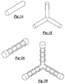
- Figs. 4-6 illustrate exemplary joints 34, 36, 38 of the present invention as well.
- Each of the joints 34, 36, 38 includes a connector 42 having multiple connector portions 44 extending away from a base portion 46 and each of those portions 44 includes heat activatable adhesive material 50 for joining the connector 42 to members 52.
- Each of those portions 44 can also include one, multiple or all of the characteristics described in relation to the portions 22, 24 of Fig. 3.
- the joint 34 of Fig. 4 is a three way axis joint with three portions 44 extending outwardly from a base portion 46 in three different directions, one, two or all three of which may be perpendicular, obtuse or acute relative to each other for joining three members 52.
- the joint 36 of Fig. 6 also includes three portions 44 extending away from a base portion 46 for joining three members 52.
- the portions 44, 46 illustrated form a "T" shape.
- the joint of Fig. 5 includes four portions 44 extending outwardly from a base portion 46 in four directions for joining four members 52.
- the connector of the present invention can have at least two, three, four or more portions extending outwardly from a base portion.
- the portions of the connector can extend away from the base portion in different directions and each of those directions is typically at an angle relative to the other one, two, three, four or more directions.
- the angle or angles are typically less than about 180°, more typically less than about 170°, even more typically less than about 140°, and possibly less than about 120° and are typically more than about 8° and even more typically greater than about 30°.
- the connectors of the illustrated joints can serve as substantially the only structural interconnection between the members that they join.
- the members that they join can be without substantial or without any direct contact with each other.
- the members are connected to each other without any welds directly connecting the members to each other and can also be without any welds indirectly to each other (e.g., through an interconnection piece welded to two or more of the members). These characteristics can be particularly desirable for articles of manufacture such as automotive vehicles.
- the member that the connectors join may contact each other without any structural attachment at those locations of contact.
- the members joined by these connectors are thus typically separate and distinct from each other.
- the members may be connected to each other by, for instance, one or more additional distinct connecting members or one or more integral portions of the members.
- joints of the present invention are particularly useful for automotive vehicles.
- the joints can be used to join members of dissimilar metals.
- metal can include materials that have non-metal materials as well as long as the amount of metal is at least 50%, 75%. 90 % or substantially entirely pure metal.
- one of the members of a joint can be formed of a first metal (e.g., aluminum) while a second of the members can be formed of a second metal that is different from and potentially incompatible with the first metal.
- incompatible metals includes metals wherein one of the metals would cause galvanic corrosion of another of the metals.
- a first member of the joint will be formed of a first metal having an electrical or electrode potential that is at least 0.25, more typically 0.4, even more typically 1.1 and even possibly 1.8 volts higher or lower than the electrical potential of a second metal of a second and/or third member of the joint.
- a table of potentials is included as page 12 of this application for assistance in determining potential relative to a hydrogen electrode and also shows potential metals possible for the members of the present invention.
- joints of present invention can provide a vehicle with a stiffer frame structure or body in white (BIW) for improved vehicle NVH.
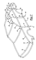
- joints of the present invention can be used to join numerous different members of an automotive vehicle.
- members any of which may be joined to each other depending upon vehicle design, include without limitation, BIW member, rails, rockers, cross-vehicle members, pillars, roof rails, roof bows, headers, door beam paddles, mirror brackets, upper and lower front body hinge pillars.
- a joint 60 interconnects an upper forward rail 62 to a cross-vehicle beam 64.
- a joint 66 interconnects the upper forward rail 62 to an A-pillar 68 and a hinge pillar 70.
- a joint 74 interconnects the hinge pillar 70 to a lower frame rail 76.
- a joint 80 interconnects the A-pillar 68 to the roof rail 82.
- a joint 88 interconnects the roof rail 82 or potentially two members 90 that comprise the roof rail to a B-pillar 92.
- a joint 96 interconnects the frame rail 76 or potentially two members 100 that comprise the frame rail 76 to the B-pillar 92.
- a joint 104 interconnects the roof rail 82, 90 to a C-pillar 110.
- a joint 112 interconnects the C-pillar 110 to a rear upper rail 116 and/or to a rear pillar portion 118.
- a joint 122 interconnects any combination of the lower C-pillar, wheelhouse, floor, cross-members and upper C-pillar.
- a joint 130 interconnects any combination of the lower frame rail 76, 100, one or more cross-members, the wheelhouse, floor and the lower C-pillar.
- the connector It is often desirable to provide the connector with attachments that at least temporarily attach the connector to the members to be joined prior to adhesion of the adhesive material. This is particularly the case when the adhesive material is configured to activate and bond to connectors and the members in a paint or e-coat processing or drying oven.
- attachments may be employed and can weld, adhere, interlock, compression fit, interference fit or otherwise attach the connector to the members to be joined.
- Mechanical attachments or fasteners can be employed to attach the connector to the members.
- Mechanical interlocks can be attached (e.g., insert molded) to the connector or integrally molded of the same material as the connector.
- Fig. 8 illustrates interlock fasteners 140 in the form of insert molded on metal clips.
- Fig. 9 illustrates interlock fasteners 142 in the form of push-pins shown as double-headed push-pins that are suitable for insertion into openings in the members and the connector.
- Fig. 10 illustrates insert molded nuts 144 in the connector 146 that are to be attached to bolts 148 extending through openings in the members.
- attachments include, without limitation, weld tabs, pop rivets, entrapment devices, insert molded weld buttons, bang plugs. It is also contemplated that the connectors may include standoff, anti-rotation devices, poke yokes or the like.
- the structural adhesive material is preferably activated to foam, expand, wet, adhere, cross-link or thermoset or any combination thereof such that the adhesive material forms a relatively strong bond between the connector and the members connected thereby.
- the structural adhesive material 50 can be activated to expand (e.g., foam) and contact and whet the internal surfaces of the members 52 than define the openings extending along the length of those members 52 and further contact and whet the surface of the connectors 42.
- the structural adhesive material 50 cross-links and/or thermosets to bond to the members 52 thereby structurally joining the members 52 to the connectors 24.
- such adhesion and bonding can take place in an e-coat oven during processing and/or assembly of the automotive vehicle and particularly the BIW.
- the connectors and adhesive material can form such joints after e-coat has been applied to the vehicle thereby allowing more robust coverage of the members and/or the connectors by the e-coat.
- connection potions of a connector can define a cavity suitable for receipt of an end of one or more tubular or other shaped members and activatable material disposed upon one or more internal surfaces defining the cavity can be activated to expand, foam, and/or adhere to one or more exterior surfaces of the members.
Landscapes
- Engineering & Computer Science (AREA)
- Chemical & Material Sciences (AREA)
- Combustion & Propulsion (AREA)
- Transportation (AREA)
- Mechanical Engineering (AREA)
- Architecture (AREA)
- Structural Engineering (AREA)
- Body Structure For Vehicles (AREA)
- Standing Axle, Rod, Or Tube Structures Coupled By Welding, Adhesion, Or Deposition (AREA)
- Mutual Connection Of Rods And Tubes (AREA)
Applications Claiming Priority (2)
| Application Number | Priority Date | Filing Date | Title |
|---|---|---|---|
| US74681006P | 2006-05-09 | 2006-05-09 | |
| US11/742,025 US8163116B2 (en) | 2006-05-09 | 2007-04-30 | Joints and a system and method of forming the joints |
Publications (1)
| Publication Number | Publication Date |
|---|---|
| EP1854704A1 true EP1854704A1 (fr) | 2007-11-14 |
Family
ID=38352513
Family Applications (1)
| Application Number | Title | Priority Date | Filing Date |
|---|---|---|---|
| EP07009213A Withdrawn EP1854704A1 (fr) | 2006-05-09 | 2007-05-08 | Joints et système et procédure de formation de joints |
Country Status (3)
| Country | Link |
|---|---|
| US (2) | US8163116B2 (fr) |
| EP (1) | EP1854704A1 (fr) |
| JP (1) | JP5273839B2 (fr) |
Cited By (11)
| Publication number | Priority date | Publication date | Assignee | Title |
|---|---|---|---|---|
| CN102963422A (zh) * | 2011-08-30 | 2013-03-13 | 福特全球技术公司 | 具有用于连接不同材料的互锁特征的车辆支撑框架 |
| CN102224038B (zh) * | 2008-11-26 | 2013-10-23 | 陶氏环球技术有限责任公司 | 声障板构件和用于在空腔中应用声障板的方法 |
| US8915530B2 (en) | 2011-07-28 | 2014-12-23 | Ford Global Technologies, Llc | Vehicle support frames with interlocking features for joining members of dissimilar materials |
| US9039061B2 (en) | 2011-08-30 | 2015-05-26 | Ford Global Technologies, Llc | Vehicle frame assemblies with threaded connections |
| CN105438266A (zh) * | 2016-01-21 | 2016-03-30 | 石宇 | 轮梁式全车身组合框架 |
| CN105599810A (zh) * | 2016-01-23 | 2016-05-25 | 石宇 | 轮梁式多轮组合车架 |
| CN105691456A (zh) * | 2016-01-24 | 2016-06-22 | 石宇 | 轮梁式无桥车架 |
| CN105711646A (zh) * | 2016-01-21 | 2016-06-29 | 石宇 | 轮梁式组合车架 |
| WO2016151093A1 (fr) | 2015-03-25 | 2016-09-29 | Zephyros, Inc. | Élément de renfort comprenant un adhésif structural sur un support de polyester |
| WO2019012235A1 (fr) * | 2017-07-12 | 2019-01-17 | Compagnie Plastic Omnium | Module avant pour véhicule |
| EP4032755A1 (fr) * | 2021-01-26 | 2022-07-27 | Volvo Construction Equipment AB | Structure de support pour véhicule et procédé d'assemblage de pièces d'une structure de support pour véhicule |
Families Citing this family (45)
| Publication number | Priority date | Publication date | Assignee | Title |
|---|---|---|---|---|
| US8002332B2 (en) | 2007-01-30 | 2011-08-23 | Zephyros, Inc. | Structural mounting insert |
| US8020924B2 (en) * | 2007-12-26 | 2011-09-20 | Sika Technology Ag | Integrated reinforcing crossmember |
| US9194408B2 (en) | 2008-02-08 | 2015-11-24 | Zephyros, Inc. | Mechanical method for improving bond joint strength |
| US8181327B2 (en) | 2008-02-08 | 2012-05-22 | Zephyros, Inc | Mechanical method for improving bond joint strength |
| GB2457896B (en) * | 2008-02-27 | 2012-12-12 | Ifor Williams Trailers Ltd | Improved horse box trailer or other trailer |
| US8293360B2 (en) * | 2008-02-27 | 2012-10-23 | Sika Technology Ag | Baffle |
| JP5146039B2 (ja) * | 2008-03-25 | 2013-02-20 | トヨタ車体株式会社 | 自動車用フロントフェンダの補強構造 |
| US8133929B2 (en) * | 2008-04-15 | 2012-03-13 | Sika Technology Ag | Method for incorporating long glass fibers into epoxy-based reinforcing resins |
| US7984919B2 (en) * | 2009-05-18 | 2011-07-26 | Zephyros, Inc. | Structural mounting insert having a non-conductive isolator |
| US8870488B2 (en) * | 2009-06-19 | 2014-10-28 | Duracase Proprietary Llc | Joint assembly with reinforcing member and foam |
| ITBO20100024A1 (it) * | 2010-01-18 | 2011-07-19 | Ferrari Spa | Barra composita per il telaio di un veicolo |
| JP5515984B2 (ja) * | 2010-04-02 | 2014-06-11 | 豊田合成株式会社 | シャシーフレーム |
| GB201012595D0 (en) | 2010-07-27 | 2010-09-08 | Zephyros Inc | Oriented structural adhesives |
| KR101199050B1 (ko) * | 2010-08-26 | 2012-11-07 | 현대자동차주식회사 | 에이-필라 연결구조 |
| US8689516B2 (en) * | 2011-03-17 | 2014-04-08 | Zephyros, Inc. | Bonding assembly |
| US8833832B2 (en) * | 2011-08-16 | 2014-09-16 | Ford Global Technologies, Llc | Node for connecting vehicle body portions |
| US20150021892A1 (en) * | 2013-07-22 | 2015-01-22 | GM Global Technology Operations LLC | Rail and method of making and using the same |
| US10577522B2 (en) | 2013-07-26 | 2020-03-03 | Zephyros, Inc. | Thermosetting adhesive films including a fibrous carrier |
| GB201318595D0 (en) | 2013-10-21 | 2013-12-04 | Zephyros Inc | Improvements in or relating to laminates |
| BR102013028618B1 (pt) * | 2013-11-06 | 2020-03-10 | Marchesan Implementos E Máquinas Agrícolas Tatú S/A | Estrutura tubular aplicada em colheitadeira de cana-de-açúcar |
| CN105916651B (zh) | 2013-12-17 | 2018-11-02 | 泽菲罗斯公司 | 一种包括纤维嵌入体的补强结构及其制造方法 |
| GB2521361B (en) * | 2013-12-17 | 2020-03-25 | Gordon Murray Design Ltd | Vehicle and chassis therefor |
| US10634473B2 (en) * | 2014-01-29 | 2020-04-28 | Raytheon Company | Internally coupleable joint |
| EP3145798B1 (fr) * | 2014-05-16 | 2019-11-13 | Divergent Technologies, Inc. | Noeuds formés modulaires pour un châssis de véhicule et leurs procédés d'utilisation |
| CN117021566A (zh) * | 2014-07-02 | 2023-11-10 | 迪根特技术公司 | 用于制造接头构件的系统和方法 |
| KR101655195B1 (ko) * | 2015-02-04 | 2016-09-22 | 현대자동차 주식회사 | 차체 멤버 연결부재 및 이를 이용한 차체 멤버 구조 |
| DE102016001241A1 (de) * | 2016-02-04 | 2017-08-10 | GM Global Technology Operations LLC (n. d. Ges. d. Staates Delaware) | Strukturknoten für eine Kraftfahrzeugkarosserie |
| US9988093B2 (en) * | 2016-09-28 | 2018-06-05 | Ford Global Technologies, Llc | Exoskeleton vehicle upper body structure |
| CN109882480A (zh) * | 2016-12-31 | 2019-06-14 | 石恬瑜 | 一种碳纤维复合材料插接接头 |
| US10183706B2 (en) * | 2017-01-20 | 2019-01-22 | Caterpillar Inc. | Nodes for frame structures |
| CN110300777B (zh) | 2017-02-17 | 2022-05-03 | 泽费罗斯股份有限公司 | 包含至少两种羧酸作为发泡剂的可活化的聚合物组合物 |
| US10106204B2 (en) * | 2017-02-23 | 2018-10-23 | Ford Global Technologies, Llc | Vehicle joint assembly with expandable structural material |
| CN106864595B (zh) * | 2017-04-10 | 2021-02-09 | 上海蔚来汽车有限公司 | 用于车架的连接件、车架组件及电动汽车 |
| US11306751B2 (en) * | 2017-08-31 | 2022-04-19 | Divergent Technologies, Inc. | Apparatus and methods for connecting tubes in transport structures |
| WO2019119203A1 (fr) * | 2017-12-18 | 2019-06-27 | 深圳市大疆创新科技有限公司 | Ensemble de pulvérisation et véhicule aérien sans pilote de protection de plantes agricoles |
| JP7123365B2 (ja) * | 2018-01-26 | 2022-08-23 | イイダ産業株式会社 | 車両構造 |
| KR102586882B1 (ko) * | 2018-03-09 | 2023-10-10 | 에이치디현대인프라코어 주식회사 | 건설기계의 캐노피 조립체 |
| US20190391563A1 (en) * | 2018-06-22 | 2019-12-26 | Divergent Technologies, Inc. | Additive manufacturing-enabled platform for modular construction of vehicles using definition nodes |
| KR102107967B1 (ko) * | 2018-11-26 | 2020-05-07 | 한국생산기술연구원 | 차대 프레임 결합용 연결부재 및 이를 이용한 차량의 가변형 차대 모듈 |
| JP7201228B2 (ja) * | 2019-03-26 | 2023-01-10 | 株式会社豊田中央研究所 | フレーム構造物及びフレーム構造物の製造方法 |
| JP7409796B2 (ja) * | 2019-07-19 | 2024-01-09 | 清水建設株式会社 | 部材の接合構造、接合方法、仮設構造物および仮設構造物の組立解体方法 |
| CN110816686A (zh) * | 2019-12-25 | 2020-02-21 | 吉林大学 | 一种铝合金车身框架专用铸铝接头 |
| KR20220021612A (ko) * | 2020-08-14 | 2022-02-22 | 현대자동차주식회사 | 차량의 차체 루프 |
| EP4284861A1 (fr) | 2021-01-27 | 2023-12-06 | Zephyros Inc. | Matériaux thermo-expansibles à faible odeur |
| WO2023247584A1 (fr) | 2022-06-24 | 2023-12-28 | Zephyros, Inc. | Gestion de fumées d'emballement thermique |
Citations (7)
| Publication number | Priority date | Publication date | Assignee | Title |
|---|---|---|---|---|
| US6068424A (en) * | 1998-02-04 | 2000-05-30 | Henkel Corporation | Three dimensional composite joint reinforcement for an automotive vehicle |
| DE19929057A1 (de) * | 1999-06-25 | 2000-12-28 | Daimler Chrysler Ag | Fahrzeugtragstruktur und Verfahren zu deren Herstellung |
| JP2001278162A (ja) * | 2000-03-31 | 2001-10-10 | Miyata Ind Co Ltd | 自転車用フレームパイプの接合方法 |
| DE10032556A1 (de) * | 2000-07-05 | 2002-01-17 | Volkswagen Ag | Karosseriebauteil in Sandwichbauweise, Verfahren zur Herstellung desselben sowie Vorrichtung zur Durchführung des Verfahrens |
| US6467834B1 (en) * | 2000-02-11 | 2002-10-22 | L&L Products | Structural reinforcement system for automotive vehicles |
| US20040045250A1 (en) * | 2002-09-05 | 2004-03-11 | Honda Giken Kogyo Kabushiki Kaisha | Frame joint structure and joining method thereof |
| US20060059807A1 (en) * | 2004-09-10 | 2006-03-23 | Jim Zimmerman | Frame system for motor vehicle |
Family Cites Families (36)
| Publication number | Priority date | Publication date | Assignee | Title |
|---|---|---|---|---|
| US1958835A (en) * | 1930-10-28 | 1934-05-15 | Alabama Pipe Company | Pipe |
| JPS551138B2 (fr) * | 1973-07-14 | 1980-01-11 | ||
| US4050721A (en) * | 1976-06-09 | 1977-09-27 | Phone-Ducs, Inc. | Reinforced plastic pipe |
| JPH0173512U (fr) * | 1987-11-06 | 1989-05-18 | ||
| JPH01131312A (ja) * | 1987-11-12 | 1989-05-24 | Miyata Ind Co Ltd | 管継手 |
| US5290857A (en) * | 1991-09-04 | 1994-03-01 | Nippon Zeon Co., Ltd. | Epoxy resin adhesive composition |
| US5266133A (en) | 1993-02-17 | 1993-11-30 | Sika Corporation | Dry expansible sealant and baffle composition and product |
| JP3655646B2 (ja) * | 1993-05-24 | 2005-06-02 | 日産自動車株式会社 | エポキシ樹脂用接着補強剤及び該補強剤を含有する自動車用エポキシ樹脂系構造接着性組成物 |
| US5458393A (en) * | 1993-08-11 | 1995-10-17 | Alumax Extrusions, Inc. | Space frame apparatus and process for the manufacture of same |
| US5932680A (en) | 1993-11-16 | 1999-08-03 | Henkel Kommanditgesellschaft Auf Aktien | Moisture-curing polyurethane hot-melt adhesive |
| EP0679501A1 (fr) | 1994-03-14 | 1995-11-02 | YMOS AKTIENGESELLSCHAFT Industrieprodukte | Matériau composite contenant un noyeau moussable |
| US5575526A (en) | 1994-05-19 | 1996-11-19 | Novamax Technologies, Inc. | Composite laminate beam for radiator support |
| US5755486A (en) | 1995-05-23 | 1998-05-26 | Novamax Technologies Holdings, Inc. | Composite structural reinforcement member |
| US6387470B1 (en) | 1998-11-05 | 2002-05-14 | Sika Corporation | Sound deadening and structural reinforcement compositions and methods of using the same |
| JP3498615B2 (ja) * | 1999-01-29 | 2004-02-16 | マツダ株式会社 | 車両の車体構造及びその製造方法 |
| US6131897A (en) | 1999-03-16 | 2000-10-17 | L & L Products, Inc. | Structural reinforcements |
| US6422575B1 (en) | 2000-03-14 | 2002-07-23 | L&L Products, Inc. | Expandable pre-formed plug |
| US6482486B1 (en) | 2000-03-14 | 2002-11-19 | L&L Products | Heat activated reinforcing sleeve |
| NL1014823C2 (nl) * | 2000-04-03 | 2001-10-04 | Corus Staal Bv | Werkwijze voor het vervaardigen van een buisvormig onderdeel. |
| JP4745487B2 (ja) * | 2000-06-22 | 2011-08-10 | 株式会社ピカコーポレイション | パイプ材と継手の接合構造並びに接合方法 |
| US6523857B1 (en) | 2000-07-05 | 2003-02-25 | Sika Corporation | Reinforcing member for interfitting channels |
| DE10117124A1 (de) | 2001-04-06 | 2002-10-10 | Henniges Elastomer Kunststoff | Verfahren und Vorrichtung zum Stoßverbinden von Profilen aus elastomerem Material |
| DE10123946B4 (de) | 2001-05-17 | 2004-11-25 | Benteler Automobiltechnik Gmbh | Sicherungselement |
| US20030192643A1 (en) * | 2002-03-15 | 2003-10-16 | Rainer Schoenfeld | Epoxy adhesive having improved impact resistance |
| US7105112B2 (en) * | 2002-11-05 | 2006-09-12 | L&L Products, Inc. | Lightweight member for reinforcing, sealing or baffling |
| MXPA04000445A (es) * | 2003-01-16 | 2004-11-12 | Dana Corp | Nodo de aluminio fundido para conectar miembros de bastidor de vehiculos y metodo para su fabricacion. |
| JP4467040B2 (ja) * | 2003-09-12 | 2010-05-26 | 本田技研工業株式会社 | 充填構造体 |
| JP2005155762A (ja) * | 2003-11-25 | 2005-06-16 | Inoue Shoji Kk | 管継手及びその管継手構造 |
| DE10359785A1 (de) | 2003-12-19 | 2005-07-21 | Daimlerchrysler Ag | Anbauteil für ein Fahrzeug |
| JP2006158792A (ja) * | 2004-12-09 | 2006-06-22 | Sri Sports Ltd | ゴルフクラブシャフト |
| GB0506513D0 (en) | 2005-03-31 | 2005-05-04 | L & L Products Inc | Improvements in or relating to joints |
| US7892396B2 (en) | 2006-06-07 | 2011-02-22 | Zephyros, Inc. | Toughened activatable material for sealing, baffling or reinforcing and method of forming same |
| US7993071B2 (en) | 2006-10-25 | 2011-08-09 | Burrell E. Clawson | Assemblies for coupling two elements and coupled assemblies |
| US8082667B2 (en) | 2007-05-31 | 2011-12-27 | The Boeing Company | Apparatus and methods for securing a first structural member and a second structural member to one another |
| US7712993B2 (en) | 2007-11-30 | 2010-05-11 | The Boeing Company | Double shear joint for bonding in structural applications |
| US8181327B2 (en) | 2008-02-08 | 2012-05-22 | Zephyros, Inc | Mechanical method for improving bond joint strength |
-
2007
- 2007-04-30 US US11/742,025 patent/US8163116B2/en active Active
- 2007-05-08 EP EP07009213A patent/EP1854704A1/fr not_active Withdrawn
- 2007-05-09 JP JP2007124048A patent/JP5273839B2/ja not_active Expired - Fee Related
-
2012
- 2012-04-10 US US13/443,316 patent/US20120205029A1/en not_active Abandoned
Patent Citations (7)
| Publication number | Priority date | Publication date | Assignee | Title |
|---|---|---|---|---|
| US6068424A (en) * | 1998-02-04 | 2000-05-30 | Henkel Corporation | Three dimensional composite joint reinforcement for an automotive vehicle |
| DE19929057A1 (de) * | 1999-06-25 | 2000-12-28 | Daimler Chrysler Ag | Fahrzeugtragstruktur und Verfahren zu deren Herstellung |
| US6467834B1 (en) * | 2000-02-11 | 2002-10-22 | L&L Products | Structural reinforcement system for automotive vehicles |
| JP2001278162A (ja) * | 2000-03-31 | 2001-10-10 | Miyata Ind Co Ltd | 自転車用フレームパイプの接合方法 |
| DE10032556A1 (de) * | 2000-07-05 | 2002-01-17 | Volkswagen Ag | Karosseriebauteil in Sandwichbauweise, Verfahren zur Herstellung desselben sowie Vorrichtung zur Durchführung des Verfahrens |
| US20040045250A1 (en) * | 2002-09-05 | 2004-03-11 | Honda Giken Kogyo Kabushiki Kaisha | Frame joint structure and joining method thereof |
| US20060059807A1 (en) * | 2004-09-10 | 2006-03-23 | Jim Zimmerman | Frame system for motor vehicle |
Cited By (17)
| Publication number | Priority date | Publication date | Assignee | Title |
|---|---|---|---|---|
| CN102224038B (zh) * | 2008-11-26 | 2013-10-23 | 陶氏环球技术有限责任公司 | 声障板构件和用于在空腔中应用声障板的方法 |
| US8915530B2 (en) | 2011-07-28 | 2014-12-23 | Ford Global Technologies, Llc | Vehicle support frames with interlocking features for joining members of dissimilar materials |
| US9108678B2 (en) | 2011-07-28 | 2015-08-18 | Ford Global Technologies, Llc | Vehicle support frames with interlocking features for joining members of dissimilar materials |
| US9039061B2 (en) | 2011-08-30 | 2015-05-26 | Ford Global Technologies, Llc | Vehicle frame assemblies with threaded connections |
| CN102963422B (zh) * | 2011-08-30 | 2016-06-01 | 福特全球技术公司 | 具有用于连接不同材料的互锁特征的车辆支撑框架 |
| CN102963422A (zh) * | 2011-08-30 | 2013-03-13 | 福特全球技术公司 | 具有用于连接不同材料的互锁特征的车辆支撑框架 |
| WO2016151093A1 (fr) | 2015-03-25 | 2016-09-29 | Zephyros, Inc. | Élément de renfort comprenant un adhésif structural sur un support de polyester |
| US11787977B2 (en) | 2015-03-25 | 2023-10-17 | Zephyros, Inc. | Reinforcement member comprising a structural adhesive on a polyester carrier |
| CN107660224A (zh) * | 2015-03-25 | 2018-02-02 | 泽费罗斯股份有限公司 | 在聚酯载体上包括结构粘合剂的增强构件 |
| US11124678B2 (en) | 2015-03-25 | 2021-09-21 | L&L Products Europe Sas | Reinforcement member comprising a structural adhesive on a polyester carrier |
| CN105711646A (zh) * | 2016-01-21 | 2016-06-29 | 石宇 | 轮梁式组合车架 |
| CN105438266A (zh) * | 2016-01-21 | 2016-03-30 | 石宇 | 轮梁式全车身组合框架 |
| CN105599810A (zh) * | 2016-01-23 | 2016-05-25 | 石宇 | 轮梁式多轮组合车架 |
| CN105691456A (zh) * | 2016-01-24 | 2016-06-22 | 石宇 | 轮梁式无桥车架 |
| FR3068948A1 (fr) * | 2017-07-12 | 2019-01-18 | Compagnie Plastic Omnium | Module avant pour vehicule |
| WO2019012235A1 (fr) * | 2017-07-12 | 2019-01-17 | Compagnie Plastic Omnium | Module avant pour véhicule |
| EP4032755A1 (fr) * | 2021-01-26 | 2022-07-27 | Volvo Construction Equipment AB | Structure de support pour véhicule et procédé d'assemblage de pièces d'une structure de support pour véhicule |
Also Published As
| Publication number | Publication date |
|---|---|
| JP5273839B2 (ja) | 2013-08-28 |
| US8163116B2 (en) | 2012-04-24 |
| US20070281523A1 (en) | 2007-12-06 |
| US20120205029A1 (en) | 2012-08-16 |
| JP2007333208A (ja) | 2007-12-27 |
Similar Documents
| Publication | Publication Date | Title |
|---|---|---|
| US8163116B2 (en) | Joints and a system and method of forming the joints | |
| US7114763B2 (en) | Automotive rail/frame energy management system | |
| US6729425B2 (en) | Adjustable reinforced structural assembly and method of use therefor | |
| US6502821B2 (en) | Automotive body panel damping system | |
| US7695040B2 (en) | Structural reinforcement member and method of use therefor | |
| US6419305B1 (en) | Automotive pillar reinforcement system | |
| US7004536B2 (en) | Attachment system and method of forming same | |
| US6561571B1 (en) | Structurally enhanced attachment of a reinforcing member | |
| US7503620B2 (en) | Structural reinforcement member and method of use therefor | |
| CA2440094C (fr) | Piece de renforcement et methode d'utilisation | |
| US6523884B2 (en) | Hydroform structural reinforcement system | |
| CA2655942C (fr) | Systeme de renfort structurel pour vehicules automobiles | |
| US20040034982A1 (en) | System and method for sealing, baffling or reinforcing | |
| US20050218697A1 (en) | Structural reinforcement system for automotive vehicles | |
| US20080202674A1 (en) | Structural reinforcements | |
| JP2005508797A (ja) | 所定の衝撃エネルギー吸収性を有する自動車用コンポジット構造部材 |
Legal Events
| Date | Code | Title | Description |
|---|---|---|---|
| PUAI | Public reference made under article 153(3) epc to a published international application that has entered the european phase |
Free format text: ORIGINAL CODE: 0009012 |
|
| 17P | Request for examination filed |
Effective date: 20070508 |
|
| AK | Designated contracting states |
Kind code of ref document: A1 Designated state(s): AT BE BG CH CY CZ DE DK EE ES FI FR GB GR HU IE IS IT LI LT LU LV MC MT NL PL PT RO SE SI SK TR |
|
| AX | Request for extension of the european patent |
Extension state: AL BA HR MK YU |
|
| RAP1 | Party data changed (applicant data changed or rights of an application transferred) |
Owner name: ZEPHYROS INC. |
|
| 17Q | First examination report despatched |
Effective date: 20080609 |
|
| AKX | Designation fees paid |
Designated state(s): AT BE BG CH CY CZ DE DK EE ES FI FR GB GR HU IE IS IT LI LT LU LV MC MT NL PL PT RO SE SI SK TR |
|
| STAA | Information on the status of an ep patent application or granted ep patent |
Free format text: STATUS: THE APPLICATION IS DEEMED TO BE WITHDRAWN |
|
| 18D | Application deemed to be withdrawn |
Effective date: 20091205 |