EP1854401B1 - Apparatus and method for measuring transit time of oxygen in blood - Google Patents
Apparatus and method for measuring transit time of oxygen in blood Download PDFInfo
- Publication number
- EP1854401B1 EP1854401B1 EP07016759A EP07016759A EP1854401B1 EP 1854401 B1 EP1854401 B1 EP 1854401B1 EP 07016759 A EP07016759 A EP 07016759A EP 07016759 A EP07016759 A EP 07016759A EP 1854401 B1 EP1854401 B1 EP 1854401B1
- Authority
- EP
- European Patent Office
- Prior art keywords
- oxygen
- transit time
- sensors
- blood
- measuring
- Prior art date
- Legal status (The legal status is an assumption and is not a legal conclusion. Google has not performed a legal analysis and makes no representation as to the accuracy of the status listed.)
- Not-in-force
Links
Images


Classifications
-
- A—HUMAN NECESSITIES
- A61—MEDICAL OR VETERINARY SCIENCE; HYGIENE
- A61B—DIAGNOSIS; SURGERY; IDENTIFICATION
- A61B5/00—Measuring for diagnostic purposes; Identification of persons
- A61B5/145—Measuring characteristics of blood in vivo, e.g. gas concentration or pH-value ; Measuring characteristics of body fluids or tissues, e.g. interstitial fluid or cerebral tissue
- A61B5/1455—Measuring characteristics of blood in vivo, e.g. gas concentration or pH-value ; Measuring characteristics of body fluids or tissues, e.g. interstitial fluid or cerebral tissue using optical sensors, e.g. spectral photometrical oximeters
- A61B5/14551—Measuring characteristics of blood in vivo, e.g. gas concentration or pH-value ; Measuring characteristics of body fluids or tissues, e.g. interstitial fluid or cerebral tissue using optical sensors, e.g. spectral photometrical oximeters for measuring blood gases
-
- A—HUMAN NECESSITIES
- A61—MEDICAL OR VETERINARY SCIENCE; HYGIENE
- A61B—DIAGNOSIS; SURGERY; IDENTIFICATION
- A61B5/00—Measuring for diagnostic purposes; Identification of persons
- A61B5/0059—Measuring for diagnostic purposes; Identification of persons using light, e.g. diagnosis by transillumination, diascopy, fluorescence
-
- A—HUMAN NECESSITIES
- A61—MEDICAL OR VETERINARY SCIENCE; HYGIENE
- A61B—DIAGNOSIS; SURGERY; IDENTIFICATION
- A61B5/00—Measuring for diagnostic purposes; Identification of persons
- A61B5/02—Detecting, measuring or recording for evaluating the cardiovascular system, e.g. pulse, heart rate, blood pressure or blood flow
- A61B5/026—Measuring blood flow
- A61B5/0261—Measuring blood flow using optical means, e.g. infrared light
Definitions
- the present invention relates to an apparatus and a method for measuring a transit time of oxygen in blood, which serves as an index of an ability of blood flow for delivering oxygen (transit time of oxygen) with regard to various organs in a living body, as a change in an oxygen concentration in blood with a non-invasive manner.
- a cardiac output has been an important parameter serving as an index of an oxygen conveying ability to various organs in a living body.
- a method of inserting a catheter to the heart, thereby measuring the cardiac output in accordance with a thermodilution method is generally known.
- the thermodilution method involves a problem of significant invasion of the living body, and is expensive as well.
- Japanese Patent No. JP-A-5 300 888 discloses a cardiac output measuring device for measuring a cardiac output by injecting dye into a vein of a living body. More specifically, the cardiac output measuring device is configured so as to obtain a cardiac output by the following procedure. A prescribed amount of dye is injected into a vein at a portion of a living body; and the dye, which has arrived at an artery at another portion of the living body, is detected. A time Ta (a mean transit time) denoting a time elapsed between completion of the dye injection and a start of detection of the arrived dye, and a time Tp denoting a time elapsed before the detected dye concentration reaches its peak concentration are measured, thereby attaining measurement of a cardiac output.
- a time Ta a mean transit time
- Tp denoting a time elapsed before the detected dye concentration reaches its peak concentration
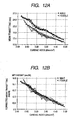
- the mean transit time of blood flow is known to be a parameter having good correlation with cardiac output. More specifically, Fig. 12A shows a relationship between the mean transit time (sec) and a cardiac index (1/min/m 2 ); and Fig. 12B shows a relationship between corrected mean transit time (sec/M) corrected by a height (M) and a cardiac index (1/min/m 2 ). As is apparent from these relationships, the mean transit time is proportional to the cardiac index. Therefore, the mean transit time of the blood flow can be employed as a parameter serving as an index of circulation of the blood flow, as in the case of cardiac output. Meanwhile, the transit time and the cardiac output have a good correlation in spite of being independent parameters of different dimensions. Accordingly, one can expect that, when the transit time of the blood flow can be measured easily, non-invasively, continuously, and at low cost, from a medical viewpoint the transit time can serve as a useful parameter for circulation monitoring in lieu of the cardiac output.
- Figs. 13A and 13B show results of measurement in a case where sensors are attached to a nasal wing and to a fingertip of a subject whose peripheral blood vessel is constricted after cardiac surgery, in which arrival times of ICG (indocyanine green) at the sensors are measured simultaneously in accordance with the above dye dilution method.
- ICG indocyanine green
- a mean transit time from injection of dye into the right atrium to arrival of the same at the nasal wing is about 30 seconds.
- a mean transit time elapsed before arrival at the fingertip is about 160 seconds.
- a transit time to a fingertip is dominated by a time elapsed before arrival at the fingertip from the aorta, and this sometimes takes a significantly long time during a period of constriction of the peripheral blood vessel. Accordingly, as is apparent, when a blood vessel is clogged due to arteriosclerosis, or the like, the blood flow is reduced, thereby delaying the transit time thereof.
- the above measurement method of injecting dye into a vessel for measuring such a transit time involves a problem of requiring invasion of a living tissue, as well as being unable to carrying out continuous measurement.
- low-invasive measurement methods that have been put into practice include a pulse dye dilution method, an impedance method, a transesophageal ultrasonic Doppler method, and a CO 2 Fick method.
- the pulse dye dilution method has a problem of requiring injection of dye into a vein, and being unable to carrying out continuous measurement.
- the impedance method has a problem of deteriorated accuracy when a subject is connected with a variety of electrodes and/or infusion lines.
- the transesophageal ultrasonic Doppler method requires insertion of an esophageal probe, thereby involving a problem of allowing measurement only under anesthesia.
- Measurement in accordance with the CO 2 Fick method can be made only with an intubated patient, thereby posing a problem of deteriorated accuracy during a period that the cardiac output is changing.
- the arterial oxygen saturation SpO 2 changes.
- the arterial oxygen saturation SpO 2 can generally be readily measured by a pulse oximeter.
- FlO 2 is taken as an input
- arterial oxygen saturation SpO 2 is taken as an output
- a positive correlation is found between the input and the output. More specifically, at a high FlO 2 , the arterial oxygen saturation SpO 2 is high; and at a low FlO 2 , the arterial oxygen saturation SpO 2 is low.
- a stepwise signal (of FlO 2 ) is input, a response signal (of arterial oxygen saturation SpO 2 ) including a certain delay time is output. By measuring this delay time, there can be obtained a transit time of oxygen through: oxygen inhalation ⁇ the lung ⁇ the heart ⁇ the aorta ⁇ the peripheral measurement positions.
- a condition of oxygen delivery to each of the prescribed positions can be ascertained on the basis of oxygen concentrations in blood obtained with use of the sensors. For instance, when, as a result of measurement of a transit time of the blood flow in right and left lower limbs, the transit time of one side is found to be long, reduction of blood flow can be detected. Hence, cases where blood flow is deteriorated by development of thrombus or atheroma can also be detected on the basis of the transit time.
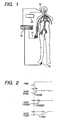
- reference numeral 10 denotes a pulse oximeter for measuring arterial oxygen saturation SpO 2 at a plurality of prescribed positions of a living body.
- the apparatus includes light absorption sensors which are to be connected to the pulse oximeter 10, and which are constituted of a first sensor 12 disposed on a nasal wing; a second sensor 14 disposed on a fingertip; and a third sensor 16 disposed on a toe, each of which belongs to the living body.
- an oxygen cylinder 20 is disposed in a mouth of the living body.
- the sensors are configured as follows.
- Each of the sensors has a photo emitter and a photo detector, and is configured to sandwich a measurement position of the living body therebetween.
- Two light-emitting diodes having light-emitting wavelengths of 660 nm and 940 nm, are used as the photo emitter.
- the light-emitting diodes are set so as to emit light alternately.
- a photo diode is used as the photo detector.
- the intensity of the thus-arrived light is converted into current by the photo diode; is further converted into voltage in the pulse oximeter; and is separated into transmitted-light signals of the respective wavelengths. Thereafter, pulse wave components of the light absorption are extracted from the two transmitted-light signals. A ratio of amplitudes of the pulse wave components; that is, an attenuation ratio ⁇ is calculated; and the ratio is converted into oxygen saturation, thereby obtaining arterial oxygen saturation SpO 2 .
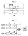
- Fig. 2 illustrates change with time of the attenuation ratios ⁇ or the arterial oxygen saturation SpO 2 in a case where, e.g., the fractional concentration of oxygen in inspired gas FlO 2 is changed by causing oxygen to be inhaled with use of the oxygen cylinder 20 in measurement of arterial oxygen saturation SpO 2 at the respective positions of the living body in the system configuration illustrated in Fig. 1 .
- the attenuation ratios ⁇ or the arterial oxygen saturation SpO 2 are detected and measured by the first through third sensors 12, 14, and 16 disposed at the respective positions of the living body.
- a time Tnose, Tfinger, Tfoot elapsed between a point in time when the FlO 2 of the living body is caused to change and a point in time when the arterial oxygen saturation SpO 2 nose, SpO 2 finger, SpO 2 foot increases at each of the measurement positions; that is, a transit time during which oxygen is transported along the blood flow, can be determined.
- the rising edges of the arterial oxygen saturation appear in the nasal wing, the fingertip of a hand, and the toe, in this order.
- the transit time in the nasal wing (head) exhibits good correlation with cardiac output.
- Fig. 4 shows a measuring apparatus according to a first embodiment of the invention.
- Light absorption sensors S1, S2, ... Sn and measuring sections M1, M2, ... Mn for obtaining the attenuation ratios ⁇ or the arterial oxygen saturation SpO 2 are respectively connected to measurement positions constituted of a toe of the right foot "Foot-R" of a subject, a left toe "Foot-L,” and a finger of the left hand “Finger-L.”
- a transit time measuring section 30 and a display (recorder) 32 are respectively connected to the sensors via the respective measuring sections M1, M2, ... Mn.
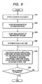
- the light absorption sensors S1, S2, ... Sn are respectively attached to the respective measurement positions of the subject (step S11), and attenuation ratios ⁇ of the arterial blood or the arterial oxygen saturation SpO 2 at the respective measurement positions are measured by the respective measuring sections M1, M2, ... Mn (step S12).
- an amount of oxygen inspired by the subject is caused to change by deep breathing or breath-holding (step S13).
- the transit time measuring section 30 can calculate a difference in transit time between the respective positions on the basis of waveforms of the attenuation ratios ⁇ of the arterial blood or the arterial oxygen saturation SpO 2 at the respective the measuring sections M1, M2, ... Mn (step S14). Meanwhile, the thus-measured difference in transit time is displayed and/or recorded in the display (recorder) 32 as required.
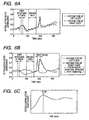
- Fig. 6A shows a result of measurement, measured by the transit time measuring apparatus of the present embodiment, of the attenuation ratio ⁇ of the arterial blood at the right toe "Foot-R" and that of the left toe "Foot-L" of a subject in a case where the subject performs deep breathing five times, and thereafter maintains a predetermined breath-holding state.
- Fig. 6B shows a result of the same measurement as above in a case where a right femoral region of the subject is pressed with a pressure of 120 mmHg.
- a difference in transit time can be taken by calculating a cross-correlation coefficient between ⁇ or SpO 2 measured at two positions, and taking a point in time when the cross-correlation coefficient attains the maximum value as the difference in transit time.
- Fig. 6C shows the cross-correlation coefficient between two waveforms shown in Fig. 6B .
- Fig. 7 shows a measuring apparatus according to a second embodiment of the invention. Components similar to those in the first embodiment will be designated by the same reference characters and repetitive explanations for those will be omitted.
- the light absorption sensors S1, S2, ... Sn and the measuring sections M1, M2, ... Mn for obtaining the attenuation ratios ⁇ or the arterial oxygen saturation SpO 2 are respectively connected to measurement positions constituted of a brow, the fingertip, and the toe, each of which belongs to the living body. Furthermore, a flow sensor 22 is disposed in the mouth of the subject for measurement of a respiratory flow or a respiratory volume at the time of deep breathing or breath-holding.
- the light absorption sensors S1, S2, ... Sn are respectively attached to the respective measurement positions of the subject (step S21), and attenuation ratios ⁇ of the arterial blood or arterial oxygen saturation SpO 2 at the respective measurement positions are measured by the respective measuring sections M1, M2, ... Mn (step S22).
- the FIO 2 of the subject is caused to change by deep breathing or breath-holding, and, in conjunction therewith, the respiratory flow or the respiratory volume of the subject in this case is measured with use of the flow sensor 22 (step S23). Thereafter, a point in time when the FIO 2 is caused to change is detected.
- an analysis time for measurement of a transit time of oxygen in blood to be measured by the transit time measuring section 30 is set (step S24).
- the transit time is measured within the range of the thus-set analysis time (step S25, step S26). Meanwhile, the thus-measured transit time is displayed and/or recorded on the display (recorder) 32 as required.
- the thus-obtained transit time serves as an index of central circulation, which has a correlation with cardiac output.
- Fig. 9 shows a measuring apparatus according to a third embodiment of the invention. Components similar to those in the first embodiment will be designated by the same reference characters and repetitive explanations for those will be omitted.
- a switching valve 24 capable of adjusting a mixing ratio between oxygen gas from the oxygen cylinder 20 and the air to be supplied to the mouth of the subject.
- a sensor 26 for fractional concentration of oxygen in inspired gas to detect current FIO 2 is provided.
- the light absorption sensors S1, S2, ... Sn are respectively attached to the respective measurement positions of the subject (step S31), and attenuation ratios ⁇ of the arterial blood or arterial oxygen saturation SpO 2 at the respective measurement positions are measured by the respective measuring sections M1, M2, ... Mn (step S32).
- a measurement interval for the respective measuring sections M1, M2, ... Mn is set (step S33).
- a determination is made as to a time for fixed-time measurement in accordance with the measurement interval having been set in advance (step S34).
- the switching valve 24 is switched so as to adapt to an inspiration of the subject.
- the subject is caused to inhale 100% oxygen for only one breath, thereby causing the FlO 2 to change (step S35).
- the point in time when the FlO 2 is caused to change is detected.
- a transit time of oxygen in blood is measured by the transit time measuring section 30 (step S36).
- the transit time is measured within the range of the measurement time having been set in advance (step S37). Meanwhile, the thus-measured transit time is displayed and/or recorded in the display (recorder) 32 as required.
- Fig. 11A shows a correlation, measured by the transit time measuring apparatus of the present embodiment, between the attenuation ⁇ ratio of the arterial blood at each of the measurement positions and a transit time thereof in a case where the FlO 2 of the subject is caused to change.
- Fig. 11B shows, for the sake of clarifying measurement of the transit time, a correlation between differential values in the attenuation ratios ⁇ of the arterial blood and the transit time, wherein the differential values are calculated with respect to a prescribed threshold value.
- the transit time measuring apparatus of the present embodiment can perform intermittent measurement of the transit time at five-minute intervals when the FlO 2 of the subject is caused to change by switching inhalation of regular air to inhalation of 100% oxygen gas O 2 for about ten seconds at a rate of once per five minutes such that the change of the FlO 2 forms rectangular waves.
- the switching valve 24 can be switched either automatically or manually.
- a transit time can be measured without complicating respiration management for a patient.
Landscapes
- Health & Medical Sciences (AREA)
- Life Sciences & Earth Sciences (AREA)
- Physics & Mathematics (AREA)
- Surgery (AREA)
- General Health & Medical Sciences (AREA)
- Engineering & Computer Science (AREA)
- Biomedical Technology (AREA)
- Heart & Thoracic Surgery (AREA)
- Medical Informatics (AREA)
- Molecular Biology (AREA)
- Biophysics (AREA)
- Animal Behavior & Ethology (AREA)
- Pathology (AREA)
- Public Health (AREA)
- Veterinary Medicine (AREA)
- Hematology (AREA)
- Cardiology (AREA)
- Physiology (AREA)
- Spectroscopy & Molecular Physics (AREA)
- Optics & Photonics (AREA)
- Measurement Of The Respiration, Hearing Ability, Form, And Blood Characteristics Of Living Organisms (AREA)
- Measuring Pulse, Heart Rate, Blood Pressure Or Blood Flow (AREA)
Applications Claiming Priority (3)
| Application Number | Priority Date | Filing Date | Title |
|---|---|---|---|
| JP2005021087 | 2005-01-28 | ||
| JP2005097080A JP2006231012A (ja) | 2005-01-28 | 2005-03-30 | 酸素運搬の循環時間測定方法および装置 |
| EP06001881A EP1685796A1 (en) | 2005-01-28 | 2006-01-30 | Apparatus and method for measuring transit time of oxygen in blood |
Related Parent Applications (1)
| Application Number | Title | Priority Date | Filing Date |
|---|---|---|---|
| EP06001881A Division EP1685796A1 (en) | 2005-01-28 | 2006-01-30 | Apparatus and method for measuring transit time of oxygen in blood |
Publications (2)
| Publication Number | Publication Date |
|---|---|
| EP1854401A1 EP1854401A1 (en) | 2007-11-14 |
| EP1854401B1 true EP1854401B1 (en) | 2009-07-15 |
Family
ID=36076036
Family Applications (2)
| Application Number | Title | Priority Date | Filing Date |
|---|---|---|---|
| EP07016759A Not-in-force EP1854401B1 (en) | 2005-01-28 | 2006-01-30 | Apparatus and method for measuring transit time of oxygen in blood |
| EP06001881A Ceased EP1685796A1 (en) | 2005-01-28 | 2006-01-30 | Apparatus and method for measuring transit time of oxygen in blood |
Family Applications After (1)
| Application Number | Title | Priority Date | Filing Date |
|---|---|---|---|
| EP06001881A Ceased EP1685796A1 (en) | 2005-01-28 | 2006-01-30 | Apparatus and method for measuring transit time of oxygen in blood |
Country Status (4)
| Country | Link |
|---|---|
| US (1) | US7376452B2 (enExample) |
| EP (2) | EP1854401B1 (enExample) |
| JP (1) | JP2006231012A (enExample) |
| DE (1) | DE602006007814D1 (enExample) |
Families Citing this family (25)
| Publication number | Priority date | Publication date | Assignee | Title |
|---|---|---|---|---|
| US20040015091A1 (en) * | 2002-04-01 | 2004-01-22 | Aspect Medical Systems | System and method of assessment of arousal, pain and stress during anesthesia and sedation |
| CN1973762A (zh) * | 2005-11-28 | 2007-06-06 | 人宇生物科技股份有限公司 | 利用呼吸控制进行血液循环流速检测的方法 |
| US8808193B2 (en) * | 2007-09-11 | 2014-08-19 | Carefusion 207, Inc. | Regional oxygen uptake/perfusion measuring device and method |
| US20110034788A1 (en) * | 2009-08-04 | 2011-02-10 | Nellcor Puritan Bennett Llc | Methods and apparatus for using multiple sensors to measure differential blood transport time in a patient |
| JP5302257B2 (ja) * | 2010-04-05 | 2013-10-02 | 建夫 斎藤 | 組織血流量測定装置及び組織血流量測定用プログラム |
| WO2013148180A1 (en) * | 2012-03-27 | 2013-10-03 | The University Of Vermont And State Agricultural College | Non-invasive methods for determining cardiac output |
| US9180260B2 (en) | 2013-08-30 | 2015-11-10 | Covidien Lp | Systems and methods for monitoring an injection procedure |
| JP6298278B2 (ja) | 2013-12-04 | 2018-03-20 | 日本光電工業株式会社 | 生体信号測定システム |
| JP6628720B2 (ja) * | 2014-06-13 | 2020-01-15 | 国立大学法人九州大学 | 循環時間測定装置、推定心拍出量算出装置、循環時間測定方法、推定心拍出量算出方法及びプログラム |
| JP6378051B2 (ja) | 2014-11-11 | 2018-08-22 | 日本光電工業株式会社 | 測定システム、及び測定装置 |
| JP6713252B2 (ja) * | 2015-03-30 | 2020-06-24 | 日本光電工業株式会社 | 生体情報測定システム |
| JP2017153845A (ja) | 2016-03-04 | 2017-09-07 | 日本光電工業株式会社 | 生体情報測定装置、混合静脈血酸素飽和度推定方法、及びプログラム |
| JP7091763B2 (ja) | 2018-03-23 | 2022-06-28 | 富士フイルムビジネスイノベーション株式会社 | 生体情報測定装置、及び生体情報測定プログラム |
| JP7102833B2 (ja) * | 2018-03-23 | 2022-07-20 | 富士フイルムビジネスイノベーション株式会社 | 生体情報測定装置、及び生体情報測定プログラム |
| JP7155563B2 (ja) * | 2018-03-23 | 2022-10-19 | 富士フイルムビジネスイノベーション株式会社 | 生体情報測定装置、及び生体情報測定プログラム |
| JP7069920B2 (ja) * | 2018-03-23 | 2022-05-18 | 富士フイルムビジネスイノベーション株式会社 | 生体情報測定装置、及び生体情報測定プログラム |
| JP2019166152A (ja) * | 2018-03-23 | 2019-10-03 | 国立大学法人九州大学 | 生体情報測定装置、及び生体情報測定プログラム |
| JP7119482B2 (ja) * | 2018-03-23 | 2022-08-17 | 富士フイルムビジネスイノベーション株式会社 | 生体情報測定装置、及び生体情報測定プログラム |
| JP6622861B2 (ja) * | 2018-06-21 | 2019-12-18 | 日本光電工業株式会社 | 測定システム、及び測定装置 |
| JP7196486B2 (ja) * | 2018-09-19 | 2022-12-27 | 富士フイルムビジネスイノベーション株式会社 | 生体情報測定装置、及び生体情報測定プログラム |
| JP7247671B2 (ja) * | 2019-03-14 | 2023-03-29 | 富士フイルムビジネスイノベーション株式会社 | 生体情報測定装置、及び生体情報測定プログラム |
| KR20210029873A (ko) * | 2019-09-06 | 2021-03-17 | 삼성전자주식회사 | 전자 장치 및 그를 이용한 바이탈 사인 획득 방법 |
| JP7363376B2 (ja) * | 2019-10-30 | 2023-10-18 | 富士フイルムビジネスイノベーション株式会社 | 生体情報測定装置、及び生体情報測定プログラム |
| JP2021069613A (ja) * | 2019-10-30 | 2021-05-06 | 国立大学法人九州大学 | 生体情報測定装置、及び生体情報測定プログラム |
| JP7732291B2 (ja) * | 2021-09-07 | 2025-09-02 | 富士フイルムビジネスイノベーション株式会社 | 生体情報測定装置、及び生体情報測定プログラム |
Family Cites Families (15)
| Publication number | Priority date | Publication date | Assignee | Title |
|---|---|---|---|---|
| US911328A (en) * | 1908-06-18 | 1909-02-02 | Josephus C Plank | Heater. |
| US4281645A (en) * | 1977-06-28 | 1981-08-04 | Duke University, Inc. | Method and apparatus for monitoring metabolism in body organs |
| JPS6234531A (ja) * | 1985-08-08 | 1987-02-14 | コーリン電子株式会社 | 脈波伝播速度測定方法 |
| DE69123954T2 (de) * | 1991-03-07 | 1997-04-30 | Hamamatsu Photonics Kk | Anordnung zur Messung des Sauerstoffgehaltes im Gewebe |
| JP3028152B2 (ja) | 1992-04-27 | 2000-04-04 | 日本光電工業株式会社 | 心拍出量計 |
| JPH09192118A (ja) * | 1996-01-18 | 1997-07-29 | Aisan Ind Co Ltd | 酸素消費量測定装置 |
| US5810723A (en) * | 1996-12-05 | 1998-09-22 | Essential Medical Devices | Non-invasive carboxyhemoglobin analyer |
| EP1082050B1 (en) * | 1998-06-03 | 2011-08-24 | Masimo Corporation | Stereo pulse oximeter |
| JP2961608B1 (ja) | 1998-10-02 | 1999-10-12 | 建夫 斎藤 | 酸素飽和度測定装置 |
| US6565515B2 (en) * | 1999-05-06 | 2003-05-20 | Colin Corporation | Pulse-wave-propagation-velocity-relating-information obtaining apparatus and blood-pressure-index measuring apparatus |
| JP3140007B2 (ja) * | 1999-05-06 | 2001-03-05 | 日本コーリン株式会社 | 下肢上肢血圧指数測定装置 |
| US6577884B1 (en) * | 2000-06-19 | 2003-06-10 | The General Hospital Corporation | Detection of stroke events using diffuse optical tomagraphy |
| US6819950B2 (en) | 2000-10-06 | 2004-11-16 | Alexander K. Mills | Method for noninvasive continuous determination of physiologic characteristics |
| JP2005507298A (ja) * | 2001-11-07 | 2005-03-17 | ミルズ、アレキサンダー・ケー | 生理学的特性を,非侵襲的に連続測定する方法 |
| JP4266117B2 (ja) * | 2003-03-03 | 2009-05-20 | リコーエレメックス株式会社 | 超音波流量計 |
-
2005
- 2005-03-30 JP JP2005097080A patent/JP2006231012A/ja active Pending
-
2006
- 2006-01-30 US US11/341,421 patent/US7376452B2/en active Active
- 2006-01-30 EP EP07016759A patent/EP1854401B1/en not_active Not-in-force
- 2006-01-30 DE DE602006007814T patent/DE602006007814D1/de active Active
- 2006-01-30 EP EP06001881A patent/EP1685796A1/en not_active Ceased
Also Published As
| Publication number | Publication date |
|---|---|
| US7376452B2 (en) | 2008-05-20 |
| JP2006231012A (ja) | 2006-09-07 |
| EP1854401A1 (en) | 2007-11-14 |
| US20060173258A1 (en) | 2006-08-03 |
| DE602006007814D1 (de) | 2009-08-27 |
| EP1685796A1 (en) | 2006-08-02 |
Similar Documents
| Publication | Publication Date | Title |
|---|---|---|
| EP1854401B1 (en) | Apparatus and method for measuring transit time of oxygen in blood | |
| US11857302B2 (en) | Method, logic unit and system for determining a parameter representative for the patient's volume responsiveness | |
| US8551006B2 (en) | Method for determining hemodynamic effects | |
| US6413226B1 (en) | Method and apparatus for determining cardiac output | |
| US9788768B2 (en) | Physiological parameter tracking system | |
| EP2301613B2 (en) | Apparatus for assessing fluid balance status of a subject | |
| US20100130874A1 (en) | Apparatus and method for determining a physiologic parameter | |
| US20210282668A1 (en) | Non-invasive determination of airway resistance | |
| US6517496B1 (en) | Airway-based cardiac output monitor and methods for using same | |
| US20110082357A1 (en) | Method and apparatus for co2 evaluation | |
| US20140073890A1 (en) | Systems and methods for determining fluid responsiveness | |
| US20250276140A1 (en) | Non-invasive estimation of hemodynamic parameters during mechanical ventilation | |
| WO2006119546A1 (en) | Pulmonary capnodynamic method for continuous non-invasive measurement of cardiac output | |
| US11045105B2 (en) | Determination of cardiac output or effective pulmonary blood flow during mechanical ventilation | |
| US20230148884A1 (en) | Method and device for determining volemic status and vascular tone | |
| Davies et al. | In-Ear Measurement of Blood Oxygen Saturation: An Ambulatory Tool Needed To Detect The Delayed Life-Threatening Hypoxaemia in COVID-19 | |
| Kalmar et al. | Technology report: ccNexfin monitor | |
| Jones et al. | Respiratory monitoring | |
| Natalini | Variations in Photoplethysmographic Waveform During Mechanical Ventilation | |
| JP2019162315A (ja) | 検査装置 | |
| Desai et al. | substrate/oxygen delivery and metabolic waste/carbon dioxide (CO2) | |
| AU2005232306A1 (en) | Method and apparatus for determining cardiac output |
Legal Events
| Date | Code | Title | Description |
|---|---|---|---|
| PUAI | Public reference made under article 153(3) epc to a published international application that has entered the european phase |
Free format text: ORIGINAL CODE: 0009012 |
|
| 17P | Request for examination filed |
Effective date: 20070827 |
|
| AC | Divisional application: reference to earlier application |
Ref document number: 1685796 Country of ref document: EP Kind code of ref document: P |
|
| AK | Designated contracting states |
Kind code of ref document: A1 Designated state(s): AT BE BG CH CY CZ DE DK EE ES FI FR GB GR HU IE IS IT LI LT LU LV MC NL PL PT RO SE SI SK TR |
|
| AKX | Designation fees paid |
Designated state(s): AT BE BG CH CY CZ DE DK EE ES FI FR GB GR HU IE IS IT LI LT LU LV MC NL PL PT RO SE SI SK TR |
|
| GRAP | Despatch of communication of intention to grant a patent |
Free format text: ORIGINAL CODE: EPIDOSNIGR1 |
|
| GRAS | Grant fee paid |
Free format text: ORIGINAL CODE: EPIDOSNIGR3 |
|
| GRAA | (expected) grant |
Free format text: ORIGINAL CODE: 0009210 |
|
| AC | Divisional application: reference to earlier application |
Ref document number: 1685796 Country of ref document: EP Kind code of ref document: P |
|
| AK | Designated contracting states |
Kind code of ref document: B1 Designated state(s): AT BE BG CH CY CZ DE DK EE ES FI FR GB GR HU IE IS IT LI LT LU LV MC NL PL PT RO SE SI SK TR |
|
| REG | Reference to a national code |
Ref country code: CH Ref legal event code: EP Ref country code: GB Ref legal event code: FG4D |
|
| REG | Reference to a national code |
Ref country code: IE Ref legal event code: FG4D |
|
| REF | Corresponds to: |
Ref document number: 602006007814 Country of ref document: DE Date of ref document: 20090827 Kind code of ref document: P |
|
| NLV1 | Nl: lapsed or annulled due to failure to fulfill the requirements of art. 29p and 29m of the patents act | ||
| PG25 | Lapsed in a contracting state [announced via postgrant information from national office to epo] |
Ref country code: AT Free format text: LAPSE BECAUSE OF FAILURE TO SUBMIT A TRANSLATION OF THE DESCRIPTION OR TO PAY THE FEE WITHIN THE PRESCRIBED TIME-LIMIT Effective date: 20090715 Ref country code: LT Free format text: LAPSE BECAUSE OF FAILURE TO SUBMIT A TRANSLATION OF THE DESCRIPTION OR TO PAY THE FEE WITHIN THE PRESCRIBED TIME-LIMIT Effective date: 20090715 Ref country code: SE Free format text: LAPSE BECAUSE OF FAILURE TO SUBMIT A TRANSLATION OF THE DESCRIPTION OR TO PAY THE FEE WITHIN THE PRESCRIBED TIME-LIMIT Effective date: 20090715 Ref country code: IS Free format text: LAPSE BECAUSE OF FAILURE TO SUBMIT A TRANSLATION OF THE DESCRIPTION OR TO PAY THE FEE WITHIN THE PRESCRIBED TIME-LIMIT Effective date: 20091115 Ref country code: ES Free format text: LAPSE BECAUSE OF FAILURE TO SUBMIT A TRANSLATION OF THE DESCRIPTION OR TO PAY THE FEE WITHIN THE PRESCRIBED TIME-LIMIT Effective date: 20091026 |
|
| PG25 | Lapsed in a contracting state [announced via postgrant information from national office to epo] |
Ref country code: LV Free format text: LAPSE BECAUSE OF FAILURE TO SUBMIT A TRANSLATION OF THE DESCRIPTION OR TO PAY THE FEE WITHIN THE PRESCRIBED TIME-LIMIT Effective date: 20090715 Ref country code: PL Free format text: LAPSE BECAUSE OF FAILURE TO SUBMIT A TRANSLATION OF THE DESCRIPTION OR TO PAY THE FEE WITHIN THE PRESCRIBED TIME-LIMIT Effective date: 20090715 Ref country code: SI Free format text: LAPSE BECAUSE OF FAILURE TO SUBMIT A TRANSLATION OF THE DESCRIPTION OR TO PAY THE FEE WITHIN THE PRESCRIBED TIME-LIMIT Effective date: 20090715 Ref country code: NL Free format text: LAPSE BECAUSE OF FAILURE TO SUBMIT A TRANSLATION OF THE DESCRIPTION OR TO PAY THE FEE WITHIN THE PRESCRIBED TIME-LIMIT Effective date: 20090715 |
|
| PG25 | Lapsed in a contracting state [announced via postgrant information from national office to epo] |
Ref country code: BG Free format text: LAPSE BECAUSE OF FAILURE TO SUBMIT A TRANSLATION OF THE DESCRIPTION OR TO PAY THE FEE WITHIN THE PRESCRIBED TIME-LIMIT Effective date: 20091015 Ref country code: PT Free format text: LAPSE BECAUSE OF FAILURE TO SUBMIT A TRANSLATION OF THE DESCRIPTION OR TO PAY THE FEE WITHIN THE PRESCRIBED TIME-LIMIT Effective date: 20091115 |
|
| PG25 | Lapsed in a contracting state [announced via postgrant information from national office to epo] |
Ref country code: DK Free format text: LAPSE BECAUSE OF FAILURE TO SUBMIT A TRANSLATION OF THE DESCRIPTION OR TO PAY THE FEE WITHIN THE PRESCRIBED TIME-LIMIT Effective date: 20090715 Ref country code: CZ Free format text: LAPSE BECAUSE OF FAILURE TO SUBMIT A TRANSLATION OF THE DESCRIPTION OR TO PAY THE FEE WITHIN THE PRESCRIBED TIME-LIMIT Effective date: 20090715 Ref country code: RO Free format text: LAPSE BECAUSE OF FAILURE TO SUBMIT A TRANSLATION OF THE DESCRIPTION OR TO PAY THE FEE WITHIN THE PRESCRIBED TIME-LIMIT Effective date: 20090715 Ref country code: EE Free format text: LAPSE BECAUSE OF FAILURE TO SUBMIT A TRANSLATION OF THE DESCRIPTION OR TO PAY THE FEE WITHIN THE PRESCRIBED TIME-LIMIT Effective date: 20090715 |
|
| PLBE | No opposition filed within time limit |
Free format text: ORIGINAL CODE: 0009261 |
|
| STAA | Information on the status of an ep patent application or granted ep patent |
Free format text: STATUS: NO OPPOSITION FILED WITHIN TIME LIMIT |
|
| PG25 | Lapsed in a contracting state [announced via postgrant information from national office to epo] |
Ref country code: SK Free format text: LAPSE BECAUSE OF FAILURE TO SUBMIT A TRANSLATION OF THE DESCRIPTION OR TO PAY THE FEE WITHIN THE PRESCRIBED TIME-LIMIT Effective date: 20090715 Ref country code: BE Free format text: LAPSE BECAUSE OF FAILURE TO SUBMIT A TRANSLATION OF THE DESCRIPTION OR TO PAY THE FEE WITHIN THE PRESCRIBED TIME-LIMIT Effective date: 20090715 |
|
| 26N | No opposition filed |
Effective date: 20100416 |
|
| PG25 | Lapsed in a contracting state [announced via postgrant information from national office to epo] |
Ref country code: MC Free format text: LAPSE BECAUSE OF NON-PAYMENT OF DUE FEES Effective date: 20100131 |
|
| REG | Reference to a national code |
Ref country code: CH Ref legal event code: PL |
|
| GBPC | Gb: european patent ceased through non-payment of renewal fee |
Effective date: 20100130 |
|
| REG | Reference to a national code |
Ref country code: FR Ref legal event code: ST Effective date: 20100930 |
|
| PG25 | Lapsed in a contracting state [announced via postgrant information from national office to epo] |
Ref country code: LI Free format text: LAPSE BECAUSE OF NON-PAYMENT OF DUE FEES Effective date: 20100131 Ref country code: GR Free format text: LAPSE BECAUSE OF FAILURE TO SUBMIT A TRANSLATION OF THE DESCRIPTION OR TO PAY THE FEE WITHIN THE PRESCRIBED TIME-LIMIT Effective date: 20091016 Ref country code: FR Free format text: LAPSE BECAUSE OF NON-PAYMENT OF DUE FEES Effective date: 20100201 Ref country code: CH Free format text: LAPSE BECAUSE OF NON-PAYMENT OF DUE FEES Effective date: 20100131 |
|
| PG25 | Lapsed in a contracting state [announced via postgrant information from national office to epo] |
Ref country code: GB Free format text: LAPSE BECAUSE OF NON-PAYMENT OF DUE FEES Effective date: 20100130 |
|
| PG25 | Lapsed in a contracting state [announced via postgrant information from national office to epo] |
Ref country code: IE Free format text: LAPSE BECAUSE OF NON-PAYMENT OF DUE FEES Effective date: 20100130 |
|
| PG25 | Lapsed in a contracting state [announced via postgrant information from national office to epo] |
Ref country code: IT Free format text: LAPSE BECAUSE OF FAILURE TO SUBMIT A TRANSLATION OF THE DESCRIPTION OR TO PAY THE FEE WITHIN THE PRESCRIBED TIME-LIMIT Effective date: 20090715 |
|
| PG25 | Lapsed in a contracting state [announced via postgrant information from national office to epo] |
Ref country code: CY Free format text: LAPSE BECAUSE OF FAILURE TO SUBMIT A TRANSLATION OF THE DESCRIPTION OR TO PAY THE FEE WITHIN THE PRESCRIBED TIME-LIMIT Effective date: 20090715 |
|
| PG25 | Lapsed in a contracting state [announced via postgrant information from national office to epo] |
Ref country code: HU Free format text: LAPSE BECAUSE OF FAILURE TO SUBMIT A TRANSLATION OF THE DESCRIPTION OR TO PAY THE FEE WITHIN THE PRESCRIBED TIME-LIMIT Effective date: 20100116 Ref country code: LU Free format text: LAPSE BECAUSE OF NON-PAYMENT OF DUE FEES Effective date: 20100130 Ref country code: FI Free format text: LAPSE BECAUSE OF FAILURE TO SUBMIT A TRANSLATION OF THE DESCRIPTION OR TO PAY THE FEE WITHIN THE PRESCRIBED TIME-LIMIT Effective date: 20090715 |
|
| PG25 | Lapsed in a contracting state [announced via postgrant information from national office to epo] |
Ref country code: TR Free format text: LAPSE BECAUSE OF FAILURE TO SUBMIT A TRANSLATION OF THE DESCRIPTION OR TO PAY THE FEE WITHIN THE PRESCRIBED TIME-LIMIT Effective date: 20090715 |
|
| PGFP | Annual fee paid to national office [announced via postgrant information from national office to epo] |
Ref country code: DE Payment date: 20180117 Year of fee payment: 13 |
|
| REG | Reference to a national code |
Ref country code: DE Ref legal event code: R119 Ref document number: 602006007814 Country of ref document: DE |
|
| PG25 | Lapsed in a contracting state [announced via postgrant information from national office to epo] |
Ref country code: DE Free format text: LAPSE BECAUSE OF NON-PAYMENT OF DUE FEES Effective date: 20190801 |