EP2301613B2 - Apparatus for assessing fluid balance status of a subject - Google Patents
Apparatus for assessing fluid balance status of a subject Download PDFInfo
- Publication number
- EP2301613B2 EP2301613B2 EP10179658.9A EP10179658A EP2301613B2 EP 2301613 B2 EP2301613 B2 EP 2301613B2 EP 10179658 A EP10179658 A EP 10179658A EP 2301613 B2 EP2301613 B2 EP 2301613B2
- Authority
- EP
- European Patent Office
- Prior art keywords
- change
- fluid
- subject
- blood volume
- ventilation
- Prior art date
- Legal status (The legal status is an assumption and is not a legal conclusion. Google has not performed a legal analysis and makes no representation as to the accuracy of the status listed.)
- Active
Links
- 239000012530 fluid Substances 0.000 title claims description 101
- 210000004369 blood Anatomy 0.000 claims description 82
- 239000008280 blood Substances 0.000 claims description 82
- 230000008859 change Effects 0.000 claims description 60
- 238000009423 ventilation Methods 0.000 claims description 42
- 230000029058 respiratory gaseous exchange Effects 0.000 claims description 20
- 230000000241 respiratory effect Effects 0.000 claims description 10
- 230000004044 response Effects 0.000 claims description 10
- 230000001183 volemic effect Effects 0.000 claims description 8
- 230000003205 diastolic effect Effects 0.000 claims description 4
- 230000010412 perfusion Effects 0.000 claims description 3
- 206010021137 Hypovolaemia Diseases 0.000 description 15
- 238000000034 method Methods 0.000 description 13
- 206010020919 Hypervolaemia Diseases 0.000 description 9
- 238000010521 absorption reaction Methods 0.000 description 9
- 210000001519 tissue Anatomy 0.000 description 8
- 230000036772 blood pressure Effects 0.000 description 7
- 230000000747 cardiac effect Effects 0.000 description 7
- 238000012545 processing Methods 0.000 description 7
- 230000035488 systolic blood pressure Effects 0.000 description 7
- 210000004072 lung Anatomy 0.000 description 6
- 230000035485 pulse pressure Effects 0.000 description 6
- 238000001802 infusion Methods 0.000 description 5
- 238000001990 intravenous administration Methods 0.000 description 5
- 238000012544 monitoring process Methods 0.000 description 5
- 230000001154 acute effect Effects 0.000 description 4
- 230000017531 blood circulation Effects 0.000 description 4
- 230000000694 effects Effects 0.000 description 4
- 238000007726 management method Methods 0.000 description 4
- 238000005259 measurement Methods 0.000 description 4
- 230000002093 peripheral effect Effects 0.000 description 4
- 210000002381 plasma Anatomy 0.000 description 4
- 230000003519 ventilatory effect Effects 0.000 description 4
- CURLTUGMZLYLDI-UHFFFAOYSA-N Carbon dioxide Chemical compound O=C=O CURLTUGMZLYLDI-UHFFFAOYSA-N 0.000 description 3
- WQZGKKKJIJFFOK-GASJEMHNSA-N Glucose Natural products OC[C@H]1OC(O)[C@H](O)[C@@H](O)[C@@H]1O WQZGKKKJIJFFOK-GASJEMHNSA-N 0.000 description 3
- 230000006399 behavior Effects 0.000 description 3
- 239000008103 glucose Substances 0.000 description 3
- 230000035761 normovolemia Effects 0.000 description 3
- 239000000523 sample Substances 0.000 description 3
- 239000000243 solution Substances 0.000 description 3
- 238000002560 therapeutic procedure Methods 0.000 description 3
- 102000001554 Hemoglobins Human genes 0.000 description 2
- 108010054147 Hemoglobins Proteins 0.000 description 2
- 230000003321 amplification Effects 0.000 description 2
- 230000004872 arterial blood pressure Effects 0.000 description 2
- QVGXLLKOCUKJST-UHFFFAOYSA-N atomic oxygen Chemical compound [O] QVGXLLKOCUKJST-UHFFFAOYSA-N 0.000 description 2
- 230000002567 autonomic effect Effects 0.000 description 2
- 210000001124 body fluid Anatomy 0.000 description 2
- 239000010839 body fluid Substances 0.000 description 2
- 229910002092 carbon dioxide Inorganic materials 0.000 description 2
- 210000004027 cell Anatomy 0.000 description 2
- 239000000084 colloidal system Substances 0.000 description 2
- 239000002131 composite material Substances 0.000 description 2
- 238000001514 detection method Methods 0.000 description 2
- 238000010586 diagram Methods 0.000 description 2
- 210000002977 intracellular fluid Anatomy 0.000 description 2
- 230000031700 light absorption Effects 0.000 description 2
- 238000003199 nucleic acid amplification method Methods 0.000 description 2
- 230000003287 optical effect Effects 0.000 description 2
- 229910052760 oxygen Inorganic materials 0.000 description 2
- 239000001301 oxygen Substances 0.000 description 2
- 210000001147 pulmonary artery Anatomy 0.000 description 2
- 210000002700 urine Anatomy 0.000 description 2
- 206010014418 Electrolyte imbalance Diseases 0.000 description 1
- 206010019280 Heart failures Diseases 0.000 description 1
- 206010020772 Hypertension Diseases 0.000 description 1
- 208000001953 Hypotension Diseases 0.000 description 1
- 206010037423 Pulmonary oedema Diseases 0.000 description 1
- 206010040047 Sepsis Diseases 0.000 description 1
- 208000004301 Sinus Arrhythmia Diseases 0.000 description 1
- 208000008784 apnea Diseases 0.000 description 1
- 210000003403 autonomic nervous system Anatomy 0.000 description 1
- 230000009286 beneficial effect Effects 0.000 description 1
- 230000005540 biological transmission Effects 0.000 description 1
- 239000010836 blood and blood product Substances 0.000 description 1
- 229940125691 blood product Drugs 0.000 description 1
- 210000000988 bone and bone Anatomy 0.000 description 1
- 238000004364 calculation method Methods 0.000 description 1
- 239000001569 carbon dioxide Substances 0.000 description 1
- 210000000748 cardiovascular system Anatomy 0.000 description 1
- 230000001419 dependent effect Effects 0.000 description 1
- 230000035487 diastolic blood pressure Effects 0.000 description 1
- 239000003814 drug Substances 0.000 description 1
- 229940079593 drug Drugs 0.000 description 1
- 238000012377 drug delivery Methods 0.000 description 1
- 210000000624 ear auricle Anatomy 0.000 description 1
- 230000002526 effect on cardiovascular system Effects 0.000 description 1
- 238000011156 evaluation Methods 0.000 description 1
- 239000000284 extract Substances 0.000 description 1
- 239000007789 gas Substances 0.000 description 1
- 230000036541 health Effects 0.000 description 1
- 230000000004 hemodynamic effect Effects 0.000 description 1
- 230000036543 hypotension Effects 0.000 description 1
- 230000002757 inflammatory effect Effects 0.000 description 1
- 238000002642 intravenous therapy Methods 0.000 description 1
- 238000012423 maintenance Methods 0.000 description 1
- 238000002483 medication Methods 0.000 description 1
- 230000035764 nutrition Effects 0.000 description 1
- 235000016709 nutrition Nutrition 0.000 description 1
- 239000002504 physiological saline solution Substances 0.000 description 1
- 239000000049 pigment Substances 0.000 description 1
- 230000002980 postoperative effect Effects 0.000 description 1
- 230000000644 propagated effect Effects 0.000 description 1
- 208000005333 pulmonary edema Diseases 0.000 description 1
- 238000002106 pulse oximetry Methods 0.000 description 1
- 210000005245 right atrium Anatomy 0.000 description 1
- 230000028327 secretion Effects 0.000 description 1
- 230000035945 sensitivity Effects 0.000 description 1
- 150000003384 small molecules Chemical class 0.000 description 1
- 241000894007 species Species 0.000 description 1
- 238000001356 surgical procedure Methods 0.000 description 1
- 230000002889 sympathetic effect Effects 0.000 description 1
- XLYOFNOQVPJJNP-UHFFFAOYSA-N water Substances O XLYOFNOQVPJJNP-UHFFFAOYSA-N 0.000 description 1
Images
Classifications
-
- A—HUMAN NECESSITIES
- A61—MEDICAL OR VETERINARY SCIENCE; HYGIENE
- A61B—DIAGNOSIS; SURGERY; IDENTIFICATION
- A61B5/00—Measuring for diagnostic purposes; Identification of persons
- A61B5/48—Other medical applications
- A61B5/4869—Determining body composition
- A61B5/4875—Hydration status, fluid retention of the body
-
- A—HUMAN NECESSITIES
- A61—MEDICAL OR VETERINARY SCIENCE; HYGIENE
- A61B—DIAGNOSIS; SURGERY; IDENTIFICATION
- A61B5/00—Measuring for diagnostic purposes; Identification of persons
- A61B5/02—Detecting, measuring or recording pulse, heart rate, blood pressure or blood flow; Combined pulse/heart-rate/blood pressure determination; Evaluating a cardiovascular condition not otherwise provided for, e.g. using combinations of techniques provided for in this group with electrocardiography or electroauscultation; Heart catheters for measuring blood pressure
- A61B5/024—Detecting, measuring or recording pulse rate or heart rate
- A61B5/02416—Detecting, measuring or recording pulse rate or heart rate using photoplethysmograph signals, e.g. generated by infrared radiation
-
- A—HUMAN NECESSITIES
- A61—MEDICAL OR VETERINARY SCIENCE; HYGIENE
- A61B—DIAGNOSIS; SURGERY; IDENTIFICATION
- A61B5/00—Measuring for diagnostic purposes; Identification of persons
- A61B5/145—Measuring characteristics of blood in vivo, e.g. gas concentration, pH value; Measuring characteristics of body fluids or tissues, e.g. interstitial fluid, cerebral tissue
- A61B5/1455—Measuring characteristics of blood in vivo, e.g. gas concentration, pH value; Measuring characteristics of body fluids or tissues, e.g. interstitial fluid, cerebral tissue using optical sensors, e.g. spectral photometrical oximeters
- A61B5/14551—Measuring characteristics of blood in vivo, e.g. gas concentration, pH value; Measuring characteristics of body fluids or tissues, e.g. interstitial fluid, cerebral tissue using optical sensors, e.g. spectral photometrical oximeters for measuring blood gases
-
- A—HUMAN NECESSITIES
- A61—MEDICAL OR VETERINARY SCIENCE; HYGIENE
- A61B—DIAGNOSIS; SURGERY; IDENTIFICATION
- A61B5/00—Measuring for diagnostic purposes; Identification of persons
- A61B5/41—Detecting, measuring or recording for evaluating the immune or lymphatic systems
- A61B5/412—Detecting or monitoring sepsis
-
- A—HUMAN NECESSITIES
- A61—MEDICAL OR VETERINARY SCIENCE; HYGIENE
- A61M—DEVICES FOR INTRODUCING MEDIA INTO, OR ONTO, THE BODY; DEVICES FOR TRANSDUCING BODY MEDIA OR FOR TAKING MEDIA FROM THE BODY; DEVICES FOR PRODUCING OR ENDING SLEEP OR STUPOR
- A61M16/00—Devices for influencing the respiratory system of patients by gas treatment, e.g. mouth-to-mouth respiration; Tracheal tubes
- A61M16/021—Devices for influencing the respiratory system of patients by gas treatment, e.g. mouth-to-mouth respiration; Tracheal tubes operated by electrical means
- A61M16/022—Control means therefor
- A61M16/024—Control means therefor including calculation means, e.g. using a processor
-
- A—HUMAN NECESSITIES
- A61—MEDICAL OR VETERINARY SCIENCE; HYGIENE
- A61B—DIAGNOSIS; SURGERY; IDENTIFICATION
- A61B5/00—Measuring for diagnostic purposes; Identification of persons
- A61B5/02—Detecting, measuring or recording pulse, heart rate, blood pressure or blood flow; Combined pulse/heart-rate/blood pressure determination; Evaluating a cardiovascular condition not otherwise provided for, e.g. using combinations of techniques provided for in this group with electrocardiography or electroauscultation; Heart catheters for measuring blood pressure
- A61B5/021—Measuring pressure in heart or blood vessels
Definitions
- This disclosure relates generally to the assessing of a fluid balance status of a subject, and to a procedure indicative of the fluid balance status of the subject.
- the subject is typically a mechanically ventilated patient, although the measurement may also be applied to spontaneously breathing patients.
- ventilation refers generally both to mechanically ventilated subjects and to subjects without assisted ventilation.
- US 6,974,418 discloses a method for calibrating an indicator.
- EP 0 666 056 discloses analysing changes in tidal volume.
- IV intra-venous
- Effective fluid management is based on maintenance of correct fluid balance in human body.
- the water content of the human body is divided into three main fluid compartments: blood, interstitial body fluid (between cells), and intracellular fluid.
- intracellular fluid compartment is rather stable, but because of the rapid interchange of fluids that may take place between blood plasma and the interstitial compartment in sepsis and inflammatory states, for example, fluid distribution may change continuously in acute care patients.
- blood and fluid loss may be considerable, which may lead, in an extreme case, to an acute need of blood transfusion and infusion of massive amounts of fluids.
- Excessive fluid hypertension, heart failure, pulmonary edema or electrolytic imbalance, while too little fluid (hypovolemia) may cause hypotension, hemodynamic collapse, blood centralization, or electrolyte imbalance.
- Fluid management may involve infusion of crystalloid solutions, such as physiological saline, colloids or glucose solutions, depending on which compartment of body fluid is most disturbed. Crystalloids fill both the blood plasma and the interstitial compartments, while colloids fill only the plasma compartment. Glucose (small molecule) solutions are used to correct the fluid content of the whole body. In acute care, nutrition and tight glucose control are also beneficial to the patient, and there is also clinical evidence that an effective fluid management can improve patient outcome and reduce hospital costs in acute care.
- crystalloid solutions such as physiological saline, colloids or glucose solutions
- Fluid challenge refers to rapid administration of intra-venous fluids and is normally used to detect hypovolemia.
- the effect of the administration of a fluid bolus may be monitored through a cardiac output monitor, for example, or by monitoring an appropriate physiological parameter, such as central venous pressure (CVP). If there is no clear increase in the CVP in response to the administration of the fluid, the presence of hypovolemia is likely, while a clear increase in the CVP suggests the absence of hypovolemia.
- CVP central venous pressure
- a major drawback of the fluid challenge is the rather long period needed for the evaluation, since the effect of the administered fluid in the human body is slow. Furthermore, fluid challenge involves the risk of excessive fluid administration.
- the blood pressure data is used to determine a patient blood volume status indicator, such as systolic blood pressure variation (SPV), the delta down component of SPV, or pulse pressure variation.
- SPV systolic blood pressure variation
- SPV pulse pressure variation
- a further drawback of the above methods is that they require invasive catheterization for the administration of the fluid bolus and/or for the monitoring of the physiological parameter. This is a clear disadvantage, especially if the catheter is not needed for other clinical assessments or IV drug delivery.
- the present invention provides an apparatus as defined in claim 1.
- FIG. 1 illustrates an embodiment of a system for monitoring fluid balance status (volemia status) of a mechanically ventilated patient/subject 10.
- the system comprises a physiological parameter unit 11 for measuring successive values for at least one physiological parameter responsive to the blood volume changes in the subject. Since the parameter(s) determined in unit 11 are responsive to the blood volume changes in the subject, the said parameter(s) is/are also termed blood volume parameter(s) in this context.
- the blood volume parameter(s) may be parameters derived from photoplethysmographic data, i.e., parameters that are rather closely related to blood volume changes.
- each final blood volume parameter output from unit 11 may be an enhanced parameter derived from several different blood volume parameters or from successive values of one blood volume parameter.
- the system of FIG. 1 further includes a ventilator 12 for mechanically ventilating the subject and a fluid status determination unit 13 for determining the fluid balance status of the subject.
- the determination unit 13 is connected to the physiological parameter unit for receiving the time series of the blood volume parameter(s) determined therein.
- the determination unit is further connected to the ventilator for receiving at least one ventilator control parameter from the ventilator and/or for changing at least one ventilator control parameter.
- the operation of the system may be controlled through an appropriate user interface 14, which may comprise an integrated or a separate display unit 15.
- the fluid status determination unit 13 determines the fluid balance status of the subject based on the blood volume parameter(s) received from unit 11 and the ventilator control parameters received from the ventilator 12. The determination of the fluid balance status is based on a temporary change caused deliberately in at least one ventilator control parameter. More specifically, the fluid status determination unit 13 determines the fluid balance status based on the change detected in the blood volume parameter(s) in response to the change made in the ventilator control parameters.
- the user may initiate the change in the ventilator control parameters through the user interface.
- the new control parameters may be supplied to the ventilator either directly from the user interface or through the fluid status determination unit 13.
- the ventilator and the control functionalities within the user interface and/or unit 13 thus form a control unit that may be used to produce a predetermined change in the ventilation of the subject.
- the blood volume parameter(s) to be determined in the physiological parameter unit may also be controlled through the user interface, i.e., the user may select the parameter(s) to be determined from a wider selection of possible parameters.
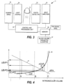
- FIG. 2 illustrates one embodiment of the steps carried out in the system of FIG. 1 .
- a physiological signal such as a photoplethysmographic signal
- a time series of at least one blood volume parameter is determined based on the waveform data of the physiological signal in the physiological parameter unit 11 (step 21).
- a change is caused in the ventilation of the subject (step 22), thereby to modulate the blood flow of the subject and thus also the at least one blood volume parameter.
- the resulting response, i.e., change, in the at least one blood volume parameter is then determined in the fluid status determination unit (step 23). Based on the response, the fluid balance status of the subject and thus also the need of fluid therapy can be assessed (step 24).
- the physiological parameter unit 11 is based on a conventional finger/ear pulse oximeter.
- FIG. 3 illustrates this embodiment of the physiological parameter unit 11.
- a pulse oximeter normally comprises a computerized measuring unit and a probe attached to the patient, typically to a finger or ear lobe.
- the probe includes a light source for sending an optical signal through the tissue and a photo detector for receiving the signal transmitted through or reflected from the tissue.
- light absorption by the tissue may be determined.
- light absorption by the tissue varies cyclically.
- Pulse oximeters focus the measurement on this pulsating arterial blood portion by determining the difference between the peak absorption during the systolic phase and the background absorption during the diastolic phase. Pulse oximetry is thus based on the assumption that the pulsating component of the absorption is due to arterial blood only.
- Traditional pulse oximeter measures absorption at two different wavelengths i.e. the probe of a traditional pulse oximeter includes two different light emitting diodes (LEDs) or lasers, while an advanced pulse oximeter may utilize a greater number of wavelengths.
- the wavelength values widely used are 660 nm (red) and 940 nm (infrared), since two species of hemoglobin have substantially different absorption at these wavelengths.
- Each LED is illuminated in turn at a frequency which is typically several hundred Hz.
- a light source 30 including at least two LEDs or lasers passes into patient tissue, such as a finger 31.
- the light propagated through or reflected from the tissue is received by a photo detector 32, which converts the optical signal received at each wavelength into an electrical signal pulse train and feeds it to an input amplifier 33.
- the amplified signal is then supplied to a control and processing unit 34, which converts the signals into digitized format for each wavelength channel.
- This digitized photoplethysmographic (PPG) signal data may then be processed or stored in a memory 36 of the control and processing unit 34.
- PPG photoplethysmographic
- the control and processing unit further controls a source drive 35 to alternately activate the LEDs or lasers.
- each LED or laser is typically illuminated several hundred times per second. With each LED is illuminated at such a high rate as compared to the pulse rate of the patient, the control and processing unit obtains a high number of samples at each wavelength for each cardiac cycle of the patient. The value of these samples varies according to the cardiac cycle of the patient.
- the PPG signal data is processed by an SpO 2 algorithm.
- the physiological parameter unit of FIG. 1 does not necessarily utilize an SpO 2 algorithm, since for the assessment of the fluid balance status the calculation of the SpO 2 values may not be necessary.
- the control and processing unit 34 executes a blood volume parameter algorithm 37 to determine at least one blood volume parameter based on the PPG signal data.
- the resulting time series may be stored in the memory 36 or supplied directly to the fluid status determination unit 13.
- a conventional pulse oximeter is thus employed to collect photoplethysmographic (PPG) waveform data from the subject.
- the control and processing unit of unit 11 determines a time series of one or more blood volume parameters, such as perfusion index (PI), plethysmographic pulse amplitude (PPA), delta plethysmographic pulse amplitude (dPPA), delta systolic plethysmographic amplitude peak (dPSA), delta diastolic plethysmographic amplitude (dPDA), or the respiratory variation of the plethysmographic baseline level (dBaseDC), where baseline level refers to the DC component of the plethysmographic signal, which represents the portion of tissue, venous blood, and non-pulsed arterial blood of the measured total absorption.
- PI perfusion index
- PPA plethysmographic pulse amplitude
- dPPA delta plethysmographic pulse amplitude
- dPSA delta s
- AC refers to the AC component of the of the plethysmographic signal, which represents the portion of the pulsed arterial blood of the measured total absorption.
- the control and processing unit extracts ventilation induced pulse variation by detecting the highest and the lowest plethysmographic pulse amplitude (PPA) over substantially one ventilation cycle.
- unit 11 may receive ventilation phase information from the ventilator or derive the phase information from the PPG signal.
- the highest and lowest peak or valley values may be extracted, and the peak value and valley value variations may be calculated.
- a high variation of PPA or PSA over a ventilation cycle i.e.
- dPPA or dPSA is a signature of hypovolemia.
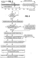
- FIG. 4 illustrates the underlying principles of the fluid balance status assessment carried out in unit 13 based on a change caused in a blood volume parameter, which is dPPA in this example.
- FIG. 4 depicts typical behavior of central venous pressure (CVP) and dPPA in response to a fluid expansion intervention at hypovolemia (around vertical line A), at normovolemia (around vertical line B), and at hypervolemia (around vertical line C).
- the thick curve 40 illustrates the behavior of central venous pressure (CVP), while the thin line 41 illustrates the behavior of dPPA.
- CVP is used here to illustrate the pressure gradient by which the right atrium of heart is filled.
- CVP is a parameter which reflects the amount of blood returning to the heart and which is directly affected by the control of lung pressure.
- the lung pressure in turn either reduces or increases the average filling pressure of the heart.
- CVP needs not to be measured, but is used here to illustrate that when ventilation (lung pressure) is changed, the resulting change in the blood volume parameter (dPPA) is dependent on the volemia status of the subject.
- dPPA blood volume parameter
- CVP may have no change or a small increase (small curve slope), and in case of severe hypovolemia even a small decrease.
- CVP around vertical line B typically show a clear increasing response.
- the shift may be carried out by temporarily changing at least one control parameter of the ventilator so that the lung pressure changes.
- the change in the ventilator control parameter then reflects as a change in the CVP, denoted ⁇ CVP in the figure.
- the extent of the resulting change in the blood volume parameter ( ⁇ BVP1, ⁇ BVP2) depends on the fluid balance status of the subject.
- the extent of change in the blood volume parameter, such as dPPA, caused by a predetermined change in the ventilation control parameter may thus be utilized to assess the fluid balance status of the subject.
- dPPA the change is more pronounced when the subject is hypovolemic ( ⁇ BVP1 > ⁇ BVP2).
- the change in the ventilation causes a change in the amount of blood returning towards the heart and thus also a horizontal shift in FIG. 4
- the change in the ventilation emulates an infusion of a fluid bolus, which is used in fluid challenge for assessing the fluid balance status of the subject.
- the assessment is quicker and involves no risk of excessive fluid administration.
- a change in the ventilation may easily be used to accomplish a shift in both horizontal directions of FIG. 4 , whereas fluid challenge always results in a shift towards hypervolemia.
- the blood volume parameter(s) generated in unit 11 is/are responsive to changes in the blood volume of the subject.
- the physiological parameter unit is based on a conventional pulse oximeter and the parameter(s) derived therein may include one or more of the PI, PPA, dPPA, dPSA, dPDA, and dBaseDC.
- the physiological parameter unit may also determine other blood volume parameters that are not based on plethysmographic data, such as parameters derived from heart rate, pulse rate, blood pressure, blood pulse pressure. The use of such parameters is discussed below.
- the operation of unit 11 may be such that the peak values of the blood pressure in consecutive heart beats are detected first. Next, the maximum and minimum values of the peak (systolic) pressures are detected over one ventilation cycle and the difference between the minimum and maximum values is calculated. In a mechanically ventilated patient, the difference is typically calculated in two segments: the delta down (dDown) and the delta up (dUp) that sum up to the total difference. Delta down is the systolic pressure change between the minimum of the systolic pressure values and a reference systolic pressure, such as the average pressure measured during a short apnea period, while the delta up is the change between the maximum value and the said reference value. In normal volemia status (normovolemia), SPV is typically 8-10 mmHg, while the down and up components thereof, dDown and dUp, are typically 5-6 mmHg and 2-4 mmHg, respectively.
- dPP delta arterial Pulse Pressure
- Low values of dPP are indicative of hypervolemia and high values of hypovolemia.
- cardiovascular parameters i.e., parameters that depend on the operation of the cardiovascular system and are thus rather closely related to blood volume changes, while the last three rows show other parameters reflecting changes in blood volume.
- Table 1 Blood circulation and peripheral perfusion, and ventilatory blood circulation variation PI, PPA, dPPA, dPSA, dPDA, dBaseDC.
- the ventilation control parameter to be controlled is the positive end-expiratory pressure (PEEP) that refers to the use of an elevated pressure during the expiratory phase of the ventilatory cycle.
- PEEP positive end-expiratory pressure
- the control of the value of this elevated pressure changes the amount of blood returning to the heart, and the control of PEEP may thus be used for accomplishing a blood volume parameter change that depends on the volemic status of the subject.
- the control of PEEP may be used in association with a blood volume parameter derived from PPG data, such as dPPA.
- Other ventilator control parameters that may be used are the ventilation rate, the tidal volume, or the ventilation airway pressure pattern (ventilation mode).
- the control of the ventilation control parameters may be done such that normoventilation is maintained all the time (end-tidal CO 2 is kept at about 5%). If the ventilation rate is the parameter to be changed, the tidal volume is altered to keep the same minute volume.
- the length of the temporary change of the ventilation control parameters may vary from one to several ventilation cycles, for example.
- the ventilator control parameters may be returned to their previous values after a duration of about 30 seconds.
- the new settings may also be maintained permanently.
- the depth of the respiratory modulation in the plethysmographic pulse wave amplitude and baseline level has larger inter- and intrapatient variability than what is observed in the corresponding blood pressure parameters.
- the sympathetic regulation of the autonomic nervous system affects the peripheral pulse wave at the measurement site.
- the autonomic amplification of the respiratory modulation depth is significant and must be taken into account when interpreting the pulse wave changes.
- FIG. 5 illustrates the dependency on the respiration rate of the depth of the respiratory modulation in a plethysmographic pulse wave amplitude.
- the autonomic amplification also depends on the fluid status of the patient itself. In normo- and hypervolemia the effect is smaller than in hypovolemia.
- a change of ventilation rate is made in the ventilator to calibrate the blood volume parameter value in reference to a predetermined respiration rate.
- the calibration is needed particularly for plethysmographic peripheral waveform parameters, but may also be used for other blood volume parameters..
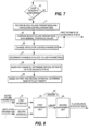
- FIG. 6 illustrates an embodiment of the operation of the fluid status determination unit 13.
- the fluid status determination unit 13 receives the blood volume parameter, such as dPPA, from the physiological parameter unit 11, and the ventilator control parameters from the ventilator 12 or from the user interface 14.
- the operation of the fluid status determination unit 13 is now described regarding a mode in which the fluid status determination unit automatically controls the ventilator. It is further assumed here that the blood volume parameter is dPPA provided from a SpO 2 measurement unit.
- the user initiates the fluid balance determination via the user interface unit 14 by requesting an automated artificial fluid challenge (step 60/yes).
- the fluid status determination unit 13 then records the current ventilator control parameters (step 61) and compares the obtained values with predetermined reference values (nominal values) under which the dPPA threshold values for hypovolemia, normovolemia and hypervolemia are pre-set (step 62). If the ventilator control parameters are at their reference values, the blood volume parameter(s) is/are recorded (step 64). However, if this is not the case, the ventilator control parameters are first controlled to their reference values (step 63), and the blood volume parameter(s) is/are then recorded after a certain time period, such as 30 seconds, needed for stable readings (step 64).
- a first estimate of fluid balance status may then be obtained by comparing the blood volume parameter with its predetermined threshold values set for each volemic state (step 65). For instance, at respiration rate of 12 breaths per minute and a tidal volume of 500 ml with inspiratory-expiratory ratio I:E of 1:2, the hypovolemic, normovolemic and hypervolemic threshold values of dPPA are, respectively, larger than 10%, between 2 and 10 % and smaller than 2 % of the plethysmographic pulse amplitude PPA.
- one of the ventilator control parameters preferably PEEP or respiration rate
- the resulting change in the blood volume parameter i.e., dPPA
- dPPA blood volume parameter
- a second estimate of the fluid status of the patient is now obtained by comparing the change in the dPPA to predetermined ranges for hypo-, normo- and hypervolemia (step 68). For instance, if PEEP is altered from zero to 2 cmH 2 O, hypovolemia is detected if the dPPA change is more than +100% from the pre-change value.
- the first estimate of the fluid status is obtained by using a pre-calculated relationship of the ventilator control parameters and the blood volume parameter, such as dPPA, thereby omitting the change of the ventilator control parameters to their reference values.
- the relationship can be stored, for example, in a look-up table that maps the dPPA values to respiration rate, tidal volume, and other ventilator control parameters, and to the threshold values of the three volemic states. Consequently, in this embodiment the values of the blood volume parameter and the ventilator control parameters are recorded immediately (step 71), without first changing the ventilator control parameters to predetermined reference values.
- step 65 the threshold values of the blood volume parameter are retrieved from the look-up table based on the current values of the blood volume parameter and the ventilator control parameters, thereby to enable the comparison and to obtain the first estimate of the fluid balance status.
- the calibration needed particularly for plethysmographic peripheral waveform parameters may in the embodiment of FIG. 7 be implemented into the look-up table by storing calibrated values corresponding to different ventilation patterns. Otherwise the embodiment of FIG. 7 corresponds to that of FIG. 6 .
- the first and second estimates of the fluid balance status which are respectively produced from the dPPA values and the dPPA change values obtained in steps 65 and 68, respectively, may take the form of user messages that indicate the dPPA value or change value and the nearest volemic state threshold value.
- the fluid status determination unit may use a set of rules for determining a combined estimate of the fluid balance status and the need of fluid therapy.
- the fluid status determination unit 13 may thus display the first and second fluid status estimates and/or a combined fluid status estimate on the display unit 15. After this, the fluid status determination unit may restore the original control parameter settings of the ventilator.
- the results of the automated fluid assessment procedure may be trended, stored in the memory of the monitor, and/or sent to a hospital information system network, for example.
- the first and second estimates may also take the form of any appropriate graphical presentation, such as a bar in which the position of the subject is indicated with respect to one or more volemic thresholds.
- the first estimate is obtained based on the blood volume parameter value and the second estimate based on the change in the blood volume parameter.
- the generation of the first estimate may be omitted. This is the case in the embodiment of FIG. 2 , where only one estimate, i.e., indicator of fluid balance status, is obtained based on the change in the blood volume parameter in response to a controlled change in the ventilation.
- the change in the blood volume parameter may be used directly as the indicator of fluid balance status presented to the user, and the user may make the decisions regarding the fluid balance status based on the said change. In case of two estimates, more weight may be put on the second estimate that is based on the change in the blood volume parameter.
- the first estimate may be used to define the ventilation change to be carried out subsequently in step 66. This is illustrated with dashed arrows in FIGs. 6 and 7 .
- a lower PEEP value may be used than if the first estimate is indicative of hypervolemia.
- the use of the first estimate for adjusting the ventilation change to be carried out improves the sensitivity of the assessment.
- the fluid status determination unit 13 and the physiological parameter unit 11 may continue the above operation and inform about the changes of the parameters on the display.
- the fluid status determination unit 13 may suggest a new artificial fluid challenge by sending a query to the user. After user acceptance, the above-described automated fluid challenge procedure may be repeated. The procedure may also be repeated at regular time intervals, such as every 30 minutes.
- the above assessment procedures may also be applied to spontaneously breathing subjects.
- the subject may change his or her ventilation pattern by a request of a physician.
- the subject may first breath normally and then take a deep breath after which he or she may return to normal breathing.
- the physiological parameter unit 11 monitors the blood volume parameter(s) and the fluid status determination unit 13 assesses the need of fluid therapy based on the changes caused the deep breath in the blood volume parameters.
- the method may further be improved by simultaneously controlling the position of the subject.
- the subject may first breath normally at a supine position, then the subject is tilted on a tilt table by for instance 10 degrees, which results in a change in the blood volume return to heart.
- the change in the blood volume parameter(s) between the supine and tilted positions is determined.
- a respiration pattern change such as a deep breath, may be made at both positions.
- a monitor assessing the fluid balance of a subject does not necessarily comprise all the elements shown in FIG. 1 , but the monitor may receive the blood volume parameters from an external device. Furthermore, the monitor may not control the ventilator, but may only detect a change that is made in the ventilation of the subject. Therefore, a simplified embodiment of the monitor comprises the elements shown in FIG. 8 .
- a first interface unit 81 is configured to receive successive values of the blood volume parameter(s) from an external unit, while a second interface unit 82 is configured to receive ventilation information and to detect, based on the received information, a change in the ventilation of the subject.
- a first assessment unit 83 is configured to monitor a response that the detected change causes in at least one blood volume parameter, thereby to obtain at least one measure of change ( ⁇ BVP).
- a second assessment unit 84 is then configured to assess the fluid balance status of the subject based on the at least one measure of change.
- the apparatus may comprise a memory 85, such as a look-up table, that holds threshold values for the different volemic states.
- the threshold values may be stored for a wide variety of ventilation patterns, especially if the ventilator is not controlled to the reference operating state prior to the ventilation change, and the memory may hold the threshold values of the volemic states for the blood volume parameter change values only or for both the blood volume parameter values and the blood volume parameter change values. That is, the apparatus may define the second estimate of the fluid balance status only or both the first and second estimates of the fluid balance status.
- the fluid status determination unit of FIG. 8 may be combined with any one or more of the elements shown in FIGs. 1 and 3 .
Description
- This disclosure relates generally to the assessing of a fluid balance status of a subject, and to a procedure indicative of the fluid balance status of the subject. The subject is typically a mechanically ventilated patient, although the measurement may also be applied to spontaneously breathing patients. Below, ventilation refers generally both to mechanically ventilated subjects and to subjects without assisted ventilation.
-
US 6,974,418 discloses a method for calibrating an indicator.EP 0 666 056 - A vast majority of hospitalized patients and all patients undergoing a surgery have an intra-venous (IV) catheter placed for delivering different types of medications and/or for infusing fluid volume and blood products, for example. Since the health and safety of the patient is often at stake, an IV infusion system must perform at the highest possible effectiveness, and the patient shall be monitored for early detection of a possible crisis situation. However, current practices in IV therapy seldom include effective crisis management with adequate monitoring and early detection of the effects of the infusions in the patient.
- Effective fluid management is based on maintenance of correct fluid balance in human body. In a simple physiological model the water content of the human body is divided into three main fluid compartments: blood, interstitial body fluid (between cells), and intracellular fluid. Usually the intracellular fluid compartment is rather stable, but because of the rapid interchange of fluids that may take place between blood plasma and the interstitial compartment in sepsis and inflammatory states, for example, fluid distribution may change continuously in acute care patients. Further, in operating theatres and during post-operative care, blood and fluid loss may be considerable, which may lead, in an extreme case, to an acute need of blood transfusion and infusion of massive amounts of fluids. Excessive fluid (hypervolemia) may lead to hypertension, heart failure, pulmonary edema or electrolytic imbalance, while too little fluid (hypovolemia) may cause hypotension, hemodynamic collapse, blood centralization, or electrolyte imbalance.
- Fluid management may involve infusion of crystalloid solutions, such as physiological saline, colloids or glucose solutions, depending on which compartment of body fluid is most disturbed. Crystalloids fill both the blood plasma and the interstitial compartments, while colloids fill only the plasma compartment. Glucose (small molecule) solutions are used to correct the fluid content of the whole body. In acute care, nutrition and tight glucose control are also beneficial to the patient, and there is also clinical evidence that an effective fluid management can improve patient outcome and reduce hospital costs in acute care.
- A conventional procedure for evaluating the fluid balance status of a patient is a method termed fluid challenge. Fluid challenge refers to rapid administration of intra-venous fluids and is normally used to detect hypovolemia. The effect of the administration of a fluid bolus may be monitored through a cardiac output monitor, for example, or by monitoring an appropriate physiological parameter, such as central venous pressure (CVP). If there is no clear increase in the CVP in response to the administration of the fluid, the presence of hypovolemia is likely, while a clear increase in the CVP suggests the absence of hypovolemia.
- A major drawback of the fluid challenge is the rather long period needed for the evaluation, since the effect of the administered fluid in the human body is slow. Furthermore, fluid challenge involves the risk of excessive fluid administration.
- It is also possible to evaluate the fluid balance status automatically through cardiological data, especially blood pressure data, obtained from the patient. In this method, the blood pressure data is used to determine a patient blood volume status indicator, such as systolic blood pressure variation (SPV), the delta down component of SPV, or pulse pressure variation.
- A further drawback of the above methods is that they require invasive catheterization for the administration of the fluid bolus and/or for the monitoring of the physiological parameter. This is a clear disadvantage, especially if the catheter is not needed for other clinical assessments or IV drug delivery.
- The above-mentioned problems are addressed herein which will be comprehended from the following specification.
- The present invention provides an apparatus as defined in claim 1.
- Various other features, objects, and advantages of the invention will be made apparent to those skilled in the art from the following detailed description and accompanying drawings.
-
-
FIG. 1 illustrates one embodiment of a system for monitoring the fluid balance status of a subject; -
FIG. 2 is a flow diagram illustrating one embodiment of the method performed in the system ofFIG. 1 ; -
FIG. 3 is a block diagram illustrating one embodiment of the physiological parameter unit ofFIG. 1 ; -
FIG. 4 illustrates the fluid balance status assessment carried out in the fluid status determination unit ofFIG. 1 based on change caused in a blood volume parameter; -
FIG. 5 illustrates the dependency between respiration rate and depth of respiration modulation present in a plethysmographic signal; and -
FIG. 6 shows an embodiment of the operation of the fluid status determination unit ofFIG. 1 ; -
FIG. 7 shows another embodiment of the operation of the fluid status determination unit ofFIG. 1 ; and -
FIG. 8 illustrates one embodiment of an apparatus for assessing the fluid balance status of a subject. -
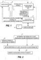
FIG. 1 illustrates an embodiment of a system for monitoring fluid balance status (volemia status) of a mechanically ventilated patient/subject 10. The system comprises aphysiological parameter unit 11 for measuring successive values for at least one physiological parameter responsive to the blood volume changes in the subject. Since the parameter(s) determined inunit 11 are responsive to the blood volume changes in the subject, the said parameter(s) is/are also termed blood volume parameter(s) in this context. As discussed below, the blood volume parameter(s) may be parameters derived from photoplethysmographic data, i.e., parameters that are rather closely related to blood volume changes. Furthermore, each final blood volume parameter output fromunit 11 may be an enhanced parameter derived from several different blood volume parameters or from successive values of one blood volume parameter. - The system of
FIG. 1 further includes aventilator 12 for mechanically ventilating the subject and a fluidstatus determination unit 13 for determining the fluid balance status of the subject. Thedetermination unit 13 is connected to the physiological parameter unit for receiving the time series of the blood volume parameter(s) determined therein. The determination unit is further connected to the ventilator for receiving at least one ventilator control parameter from the ventilator and/or for changing at least one ventilator control parameter. - The operation of the system may be controlled through an
appropriate user interface 14, which may comprise an integrated or aseparate display unit 15. The fluidstatus determination unit 13 determines the fluid balance status of the subject based on the blood volume parameter(s) received fromunit 11 and the ventilator control parameters received from theventilator 12. The determination of the fluid balance status is based on a temporary change caused deliberately in at least one ventilator control parameter. More specifically, the fluidstatus determination unit 13 determines the fluid balance status based on the change detected in the blood volume parameter(s) in response to the change made in the ventilator control parameters. The user may initiate the change in the ventilator control parameters through the user interface. The new control parameters may be supplied to the ventilator either directly from the user interface or through the fluidstatus determination unit 13. If the adjustment of the ventilator control parameters occurs through the fluidstatus determination unit 13, and the said unit is thus aware of the new control parameters, it may not be necessary to supply the control parameters as feedback information from the ventilator to the fluid status determination unit. In the embodiment ofFIG. 1 , the ventilator and the control functionalities within the user interface and/orunit 13 thus form a control unit that may be used to produce a predetermined change in the ventilation of the subject. - The blood volume parameter(s) to be determined in the physiological parameter unit may also be controlled through the user interface, i.e., the user may select the parameter(s) to be determined from a wider selection of possible parameters.
-
FIG. 2 illustrates one embodiment of the steps carried out in the system ofFIG. 1 . A physiological signal, such as a photoplethysmographic signal, is measured from the subject and a time series of at least one blood volume parameter is determined based on the waveform data of the physiological signal in the physiological parameter unit 11 (step 21). Concurrently with the determination of the time series of the at least one blood volume parameter, a change is caused in the ventilation of the subject (step 22), thereby to modulate the blood flow of the subject and thus also the at least one blood volume parameter. The resulting response, i.e., change, in the at least one blood volume parameter is then determined in the fluid status determination unit (step 23). Based on the response, the fluid balance status of the subject and thus also the need of fluid therapy can be assessed (step 24). - In an embodiment of the system, the
physiological parameter unit 11 is based on a conventional finger/ear pulse oximeter.FIG. 3 illustrates this embodiment of thephysiological parameter unit 11. A pulse oximeter normally comprises a computerized measuring unit and a probe attached to the patient, typically to a finger or ear lobe. The probe includes a light source for sending an optical signal through the tissue and a photo detector for receiving the signal transmitted through or reflected from the tissue. On the basis of the transmitted and received signals, light absorption by the tissue may be determined. During each cardiac cycle, light absorption by the tissue varies cyclically. During the diastolic phase, absorption is caused by venous blood, non-pulsating arterial blood, cells and fluids in tissue, bone, and pigments, whereas during the systolic phase there is an increase in absorption, which is caused by the inflow of arterial blood into the tissue part on which the sensor is attached. Pulse oximeters focus the measurement on this pulsating arterial blood portion by determining the difference between the peak absorption during the systolic phase and the background absorption during the diastolic phase. Pulse oximetry is thus based on the assumption that the pulsating component of the absorption is due to arterial blood only. - Traditional pulse oximeter measures absorption at two different wavelengths, i.e. the probe of a traditional pulse oximeter includes two different light emitting diodes (LEDs) or lasers, while an advanced pulse oximeter may utilize a greater number of wavelengths. The wavelength values widely used are 660 nm (red) and 940 nm (infrared), since two species of hemoglobin have substantially different absorption at these wavelengths. Each LED is illuminated in turn at a frequency which is typically several hundred Hz.
- With reference to
FIG. 3 , light transmitted from alight source 30 including at least two LEDs or lasers passes into patient tissue, such as afinger 31. The light propagated through or reflected from the tissue is received by aphoto detector 32, which converts the optical signal received at each wavelength into an electrical signal pulse train and feeds it to aninput amplifier 33. The amplified signal is then supplied to a control andprocessing unit 34, which converts the signals into digitized format for each wavelength channel. This digitized photoplethysmographic (PPG) signal data may then be processed or stored in amemory 36 of the control andprocessing unit 34. - The control and processing unit further controls a
source drive 35 to alternately activate the LEDs or lasers. As mentioned above, each LED or laser is typically illuminated several hundred times per second. With each LED is illuminated at such a high rate as compared to the pulse rate of the patient, the control and processing unit obtains a high number of samples at each wavelength for each cardiac cycle of the patient. The value of these samples varies according to the cardiac cycle of the patient. - In a normal pulse oximeter, the PPG signal data is processed by an SpO2 algorithm. However, the physiological parameter unit of
FIG. 1 does not necessarily utilize an SpO2 algorithm, since for the assessment of the fluid balance status the calculation of the SpO2 values may not be necessary. Instead, the control andprocessing unit 34 executes a bloodvolume parameter algorithm 37 to determine at least one blood volume parameter based on the PPG signal data. The resulting time series may be stored in thememory 36 or supplied directly to the fluidstatus determination unit 13. - In the embodiment of
FIG. 3 , a conventional pulse oximeter is thus employed to collect photoplethysmographic (PPG) waveform data from the subject. Based on the data, the control and processing unit ofunit 11 determines a time series of one or more blood volume parameters, such as perfusion index (PI), plethysmographic pulse amplitude (PPA), delta plethysmographic pulse amplitude (dPPA), delta systolic plethysmographic amplitude peak (dPSA), delta diastolic plethysmographic amplitude (dPDA), or the respiratory variation of the plethysmographic baseline level (dBaseDC), where baseline level refers to the DC component of the plethysmographic signal, which represents the portion of tissue, venous blood, and non-pulsed arterial blood of the measured total absorption. In order to detect the respiratory plethysmographic baseline fluctuations within a ventilation cycle, it is advantageous to analyze the total light transmission signal, i.e. the composite signal (AC+DC), before calculating the plethysmographic pulse wave (AC/DC), from which the other fluid balance parameters are extracted (AC refers to the AC component of the of the plethysmographic signal, which represents the portion of the pulsed arterial blood of the measured total absorption). - To measure the dPPA, the control and processing unit extracts ventilation induced pulse variation by detecting the highest and the lowest plethysmographic pulse amplitude (PPA) over substantially one ventilation cycle. For this,
unit 11 may receive ventilation phase information from the ventilator or derive the phase information from the PPG signal. The dPPA is then obtained as the difference in percentage from the average pulse height (dPPA=100*[PPAmax-PPAmin]/{[PPAmax+PPAmin]/2}). Alternatively, the highest and lowest peak or valley values may be extracted, and the peak value and valley value variations may be calculated. Generally, a high variation of PPA or PSA over a ventilation cycle, i.e. a large dPPA or dPSA, is a signature of hypovolemia. As mentioned above, the respiratory baseline variation can best be determined directly based on the composite signal. For each heart pulse the maxima and minima of the DC signal, DCpulseMAX and DCpulseMIN, are detected. The respiratory baseline variation can then be determined as dBaseDC=100*[DCpulseMAX-DCpulseMIN]/[(DCpulseMAX+DCpulseMIN)/2]. -
FIG. 4 illustrates the underlying principles of the fluid balance status assessment carried out inunit 13 based on a change caused in a blood volume parameter, which is dPPA in this example.FIG. 4 depicts typical behavior of central venous pressure (CVP) and dPPA in response to a fluid expansion intervention at hypovolemia (around vertical line A), at normovolemia (around vertical line B), and at hypervolemia (around vertical line C). Thethick curve 40 illustrates the behavior of central venous pressure (CVP), while thethin line 41 illustrates the behavior of dPPA. CVP is used here to illustrate the pressure gradient by which the right atrium of heart is filled. Thus, CVP is a parameter which reflects the amount of blood returning to the heart and which is directly affected by the control of lung pressure. The lung pressure in turn either reduces or increases the average filling pressure of the heart. It is to be noted that CVP needs not to be measured, but is used here to illustrate that when ventilation (lung pressure) is changed, the resulting change in the blood volume parameter (dPPA) is dependent on the volemia status of the subject. Around vertical line A, CVP may have no change or a small increase (small curve slope), and in case of severe hypovolemia even a small decrease. When more fluid is added into the patient plasma volume, the hemoglobin is diluted, but also the response to fluid expansion changes: CVP around vertical line B typically show a clear increasing response. - It is generally known that arterial blood pressure changes in phase with ventilation. This phenomen is commonly termed the ventilatory swing. Generally, the air pressure in the lungs affects the amount of blood returning to the heart; high pressure impedes the blood flow towards the heart, while low pressure facilitates the said flow. Due to the ventilatory swing, the point on which the subject is on
curve 40 ofFIG. 4 moves slightly back and forth in phase with ventilation, i.e., the CVP, or in fact the filling pressure gradient, changes in phase with ventilation. This phenomen is now utilized to assess the fluid balance status of the subject by actively causing a temporary change in the ventilation of the subject, thereby to cause a temporary horizontal shift inFIG. 4 . The shift may be carried out by temporarily changing at least one control parameter of the ventilator so that the lung pressure changes. The change in the ventilator control parameter then reflects as a change in the CVP, denoted ΔCVP in the figure. However, as can be seen from the figure, the extent of the resulting change in the blood volume parameter (ΔBVP1, ΔBVP2) depends on the fluid balance status of the subject. The extent of change in the blood volume parameter, such as dPPA, caused by a predetermined change in the ventilation control parameter may thus be utilized to assess the fluid balance status of the subject. As can be seen from the figure, in case of dPPA the change is more pronounced when the subject is hypovolemic (ΔBVP1 > ΔBVP2). - Since the change in the ventilation causes a change in the amount of blood returning towards the heart and thus also a horizontal shift in
FIG. 4 , the change in the ventilation emulates an infusion of a fluid bolus, which is used in fluid challenge for assessing the fluid balance status of the subject. However, as no actual bolus is needed in the procedure disclosed here, the assessment is quicker and involves no risk of excessive fluid administration. Furthermore, a change in the ventilation may easily be used to accomplish a shift in both horizontal directions ofFIG. 4 , whereas fluid challenge always results in a shift towards hypervolemia. - As indicated above, the blood volume parameter(s) generated in
unit 11 is/are responsive to changes in the blood volume of the subject. In the above embodiment, the physiological parameter unit is based on a conventional pulse oximeter and the parameter(s) derived therein may include one or more of the PI, PPA, dPPA, dPSA, dPDA, and dBaseDC. However, the physiological parameter unit may also determine other blood volume parameters that are not based on plethysmographic data, such as parameters derived from heart rate, pulse rate, blood pressure, blood pulse pressure. The use of such parameters is discussed below. - In the embodiments determining SPV, the operation of
unit 11 may be such that the peak values of the blood pressure in consecutive heart beats are detected first. Next, the maximum and minimum values of the peak (systolic) pressures are detected over one ventilation cycle and the difference between the minimum and maximum values is calculated. In a mechanically ventilated patient, the difference is typically calculated in two segments: the delta down (dDown) and the delta up (dUp) that sum up to the total difference. Delta down is the systolic pressure change between the minimum of the systolic pressure values and a reference systolic pressure, such as the average pressure measured during a short apnea period, while the delta up is the change between the maximum value and the said reference value. In normal volemia status (normovolemia), SPV is typically 8-10 mmHg, while the down and up components thereof, dDown and dUp, are typically 5-6 mmHg and 2-4 mmHg, respectively. - Higher SPV and dDown are responsive to blood volume changes and good indicators of hypovolemia in a mechanically ventilated patient, in which dDown can be as much as 20 mmHg and is mainly responsible of the total pressure variation. Correspondingly, low values are indicative of hypervolemia.
- Another possible blood volume parameter that may be determined in
unit 11 is the delta arterial Pulse Pressure (dPP) that reflects pulse pressure variability over one ventilation cycle. The value of dPP may be measured in percents, dPP=100*[PPmax-PPmin]/{[PPmax+PPmin]/2}, where PPmax is the maximum and PPmin the minimum of the pulse pressure values in one ventilation cycle, and each pulse pressure value represents the difference of the systolic and diastolic pressures in one heart beat. Low values of dPP are indicative of hypervolemia and high values of hypovolemia. - Some other blood volume parameters that may be determined in the
physiological parameter unit 11 are summarized in Table 1 below. The first four rows involve cardiovascular parameters, i.e., parameters that depend on the operation of the cardiovascular system and are thus rather closely related to blood volume changes, while the last three rows show other parameters reflecting changes in blood volume.Table 1: Blood circulation and peripheral perfusion, and ventilatory blood circulation variation PI, PPA, dPPA, dPSA, dPDA, dBaseDC. Blood pressure and blood pressure variation SPV, dDown, dPP, CVP, Pulmonary artery occlusion pressure (PAOP), Pulmonary artery wedge pressure (PWP), systolic Blood Pressure (sysBP), Mean Arterial Pressure (MAP) Heart rate variation Respiratory sinus arrhythmia (RSA) Cardiac ejection volume Cardiac output (CO), cardiac index (CI), stroke index (SI) Temperature Finger/toe temperature, core-peripheral temperature gradient Exhaled gas concentrations, venous oxygen saturation Venous saturation (SvO2), End tidal carbon dioxide (EtCO2), End tidal oxygen concentration (EtO2) Urine secretion Urine flow, bladder volume - In one embodiment, the ventilation control parameter to be controlled is the positive end-expiratory pressure (PEEP) that refers to the use of an elevated pressure during the expiratory phase of the ventilatory cycle. The control of the value of this elevated pressure changes the amount of blood returning to the heart, and the control of PEEP may thus be used for accomplishing a blood volume parameter change that depends on the volemic status of the subject. The control of PEEP may be used in association with a blood volume parameter derived from PPG data, such as dPPA. Other ventilator control parameters that may be used are the ventilation rate, the tidal volume, or the ventilation airway pressure pattern (ventilation mode). The control of the ventilation control parameters may be done such that normoventilation is maintained all the time (end-tidal CO2 is kept at about 5%). If the ventilation rate is the parameter to be changed, the tidal volume is altered to keep the same minute volume.
- The length of the temporary change of the ventilation control parameters may vary from one to several ventilation cycles, for example. Typically, the ventilator control parameters may be returned to their previous values after a duration of about 30 seconds. However, the new settings may also be maintained permanently.
- The depth of the respiratory modulation in the plethysmographic pulse wave amplitude and baseline level has larger inter- and intrapatient variability than what is observed in the corresponding blood pressure parameters. In addition to the lung pressure directly modulating the blood return to the heart, the sympathetic regulation of the autonomic nervous system affects the peripheral pulse wave at the measurement site. At certain respiration rates, corresponding typically to a 10 second respiration interval, the autonomic amplification of the respiratory modulation depth is significant and must be taken into account when interpreting the pulse wave changes.
FIG. 5 illustrates the dependency on the respiration rate of the depth of the respiratory modulation in a plethysmographic pulse wave amplitude. The figure shows an example of the depth of the respiration modulation in a plethysmographic signal at respiration rates of 12 and 6 breaths per minute. About at t=950 sec, the respiration rate is changed from 12 to 6 breaths per minute. As can be seen from the figure, the respiratory modulation depth at 6 breaths per minutes, dPPA6, is about two times larger than the modulation depth at the higher rate of 12 breaths per minute, dPPA12. As the fluid balance status of the patient is unchanged in the example ofFIG. 5 , the dPPA value cannot directly be used as a reliable blood volume parameter. The autonomic amplification also depends on the fluid status of the patient itself. In normo- and hypervolemia the effect is smaller than in hypovolemia. Therefore, in one embodiment, a change of ventilation rate is made in the ventilator to calibrate the blood volume parameter value in reference to a predetermined respiration rate. The calibration is needed particularly for plethysmographic peripheral waveform parameters, but may also be used for other blood volume parameters.. -
FIG. 6 illustrates an embodiment of the operation of the fluidstatus determination unit 13. The fluidstatus determination unit 13 receives the blood volume parameter, such as dPPA, from thephysiological parameter unit 11, and the ventilator control parameters from theventilator 12 or from theuser interface 14. The operation of the fluidstatus determination unit 13 is now described regarding a mode in which the fluid status determination unit automatically controls the ventilator. It is further assumed here that the blood volume parameter is dPPA provided from a SpO2 measurement unit. - The user initiates the fluid balance determination via the
user interface unit 14 by requesting an automated artificial fluid challenge (step 60/yes). The fluidstatus determination unit 13 then records the current ventilator control parameters (step 61) and compares the obtained values with predetermined reference values (nominal values) under which the dPPA threshold values for hypovolemia, normovolemia and hypervolemia are pre-set (step 62). If the ventilator control parameters are at their reference values, the blood volume parameter(s) is/are recorded (step 64). However, if this is not the case, the ventilator control parameters are first controlled to their reference values (step 63), and the blood volume parameter(s) is/are then recorded after a certain time period, such as 30 seconds, needed for stable readings (step 64). A first estimate of fluid balance status may then be obtained by comparing the blood volume parameter with its predetermined threshold values set for each volemic state (step 65). For instance, at respiration rate of 12 breaths per minute and a tidal volume of 500 ml with inspiratory-expiratory ratio I:E of 1:2, the hypovolemic, normovolemic and hypervolemic threshold values of dPPA are, respectively, larger than 10%, between 2 and 10 % and smaller than 2 % of the plethysmographic pulse amplitude PPA. - After this, one of the ventilator control parameters, preferably PEEP or respiration rate, is changed at
step 66 and the resulting change in the blood volume parameter, i.e., dPPA, is determined after a certain time interval (step 67). A second estimate of the fluid status of the patient is now obtained by comparing the change in the dPPA to predetermined ranges for hypo-, normo- and hypervolemia (step 68). For instance, if PEEP is altered from zero to 2 cmH2O, hypovolemia is detected if the dPPA change is more than +100% from the pre-change value. - In another embodiment, which is illustrated in
FIG. 7 , the first estimate of the fluid status is obtained by using a pre-calculated relationship of the ventilator control parameters and the blood volume parameter, such as dPPA, thereby omitting the change of the ventilator control parameters to their reference values. The relationship can be stored, for example, in a look-up table that maps the dPPA values to respiration rate, tidal volume, and other ventilator control parameters, and to the threshold values of the three volemic states. Consequently, in this embodiment the values of the blood volume parameter and the ventilator control parameters are recorded immediately (step 71), without first changing the ventilator control parameters to predetermined reference values. Furthermore, instep 65 the threshold values of the blood volume parameter are retrieved from the look-up table based on the current values of the blood volume parameter and the ventilator control parameters, thereby to enable the comparison and to obtain the first estimate of the fluid balance status. The calibration needed particularly for plethysmographic peripheral waveform parameters may in the embodiment ofFIG. 7 be implemented into the look-up table by storing calibrated values corresponding to different ventilation patterns. Otherwise the embodiment ofFIG. 7 corresponds to that ofFIG. 6 . - The first and second estimates of the fluid balance status, which are respectively produced from the dPPA values and the dPPA change values obtained in
steps step 69, the fluid status determination unit may use a set of rules for determining a combined estimate of the fluid balance status and the need of fluid therapy. The fluidstatus determination unit 13 may thus display the first and second fluid status estimates and/or a combined fluid status estimate on thedisplay unit 15. After this, the fluid status determination unit may restore the original control parameter settings of the ventilator. The results of the automated fluid assessment procedure may be trended, stored in the memory of the monitor, and/or sent to a hospital information system network, for example. The first and second estimates may also take the form of any appropriate graphical presentation, such as a bar in which the position of the subject is indicated with respect to one or more volemic thresholds. - In the embodiments of
FIG. 6 and7 the first estimate is obtained based on the blood volume parameter value and the second estimate based on the change in the blood volume parameter. However, the generation of the first estimate may be omitted. This is the case in the embodiment ofFIG. 2 , where only one estimate, i.e., indicator of fluid balance status, is obtained based on the change in the blood volume parameter in response to a controlled change in the ventilation. In one embodiment, the change in the blood volume parameter may be used directly as the indicator of fluid balance status presented to the user, and the user may make the decisions regarding the fluid balance status based on the said change. In case of two estimates, more weight may be put on the second estimate that is based on the change in the blood volume parameter. Furthermore, in case of two estimates the first estimate may be used to define the ventilation change to be carried out subsequently instep 66. This is illustrated with dashed arrows inFIGs. 6 and7 . For example, if the first estimate is indicative of hypovolemia, a lower PEEP value may be used than if the first estimate is indicative of hypervolemia. The use of the first estimate for adjusting the ventilation change to be carried out improves the sensitivity of the assessment. - The fluid
status determination unit 13 and thephysiological parameter unit 11 may continue the above operation and inform about the changes of the parameters on the display. In one embodiment, the fluidstatus determination unit 13 may suggest a new artificial fluid challenge by sending a query to the user. After user acceptance, the above-described automated fluid challenge procedure may be repeated. The procedure may also be repeated at regular time intervals, such as every 30 minutes. - The above assessment procedures may also be applied to spontaneously breathing subjects. In this case the subject may change his or her ventilation pattern by a request of a physician. For instance, the subject may first breath normally and then take a deep breath after which he or she may return to normal breathing. The
physiological parameter unit 11 monitors the blood volume parameter(s) and the fluidstatus determination unit 13 assesses the need of fluid therapy based on the changes caused the deep breath in the blood volume parameters. The method may further be improved by simultaneously controlling the position of the subject. The subject may first breath normally at a supine position, then the subject is tilted on a tilt table by forinstance 10 degrees, which results in a change in the blood volume return to heart. The change in the blood volume parameter(s) between the supine and tilted positions is determined. A respiration pattern change, such as a deep breath, may be made at both positions. - A monitor assessing the fluid balance of a subject does not necessarily comprise all the elements shown in
FIG. 1 , but the monitor may receive the blood volume parameters from an external device. Furthermore, the monitor may not control the ventilator, but may only detect a change that is made in the ventilation of the subject. Therefore, a simplified embodiment of the monitor comprises the elements shown inFIG. 8 . Afirst interface unit 81 is configured to receive successive values of the blood volume parameter(s) from an external unit, while asecond interface unit 82 is configured to receive ventilation information and to detect, based on the received information, a change in the ventilation of the subject. Afirst assessment unit 83 is configured to monitor a response that the detected change causes in at least one blood volume parameter, thereby to obtain at least one measure of change (ΔBVP). Asecond assessment unit 84 is then configured to assess the fluid balance status of the subject based on the at least one measure of change. As discussed above, the apparatus may comprise amemory 85, such as a look-up table, that holds threshold values for the different volemic states. The threshold values may be stored for a wide variety of ventilation patterns, especially if the ventilator is not controlled to the reference operating state prior to the ventilation change, and the memory may hold the threshold values of the volemic states for the blood volume parameter change values only or for both the blood volume parameter values and the blood volume parameter change values. That is, the apparatus may define the second estimate of the fluid balance status only or both the first and second estimates of the fluid balance status. In further embodiments of the apparatus, the fluid status determination unit ofFIG. 8 may be combined with any one or more of the elements shown inFIGs. 1 and3 .
Claims (4)
- An apparatus for assessing fluid balance status of a spontaneously breathing subject (10), the apparatus comprising:- a first interface unit (81) configured to receive successive values of at least one physiological parameter responsive to blood volume changes in the spontaneously breathing subject (10),characterized in that the apparatus further comprises- a second interface unit (82) configured to detect a change in ventilation of the spontaneously breathing subject (10);- a first assessment unit (83) configured to monitor a response that the change causes in at least one of the at least one physiological parameter, thereby to derive at least one measure of change from the at least one physiological parameter; and- a second assessment unit (84) configured to determine the fluid balance status of the spontaneously breathing subject (10) based on the at least one measure of change.
- The apparatus according to claim 1, wherein the first interface unit (81) is configured to receive the successive values of the at least one physiological parameter, in which the at least one physiological parameter is at least one of perfusion index (PI), plethysmographic pulse amplitude (PPA), delta plethysmographic pulse amplitude (dPPA), delta systolic plethysmographic amplitude peak (dPSA), delta diastolic plethysmographic amplitude (dPDA), and the respiratory variation of the plethysmographic baseline level (dBaseDC).
- The apparatus according to any of the preceding claims, wherein the second assessment unit (84) is configured to compare the at least one measure of change with predetermined threshold values of different volemic states.
- The apparatus according to claim 3, wherein the apparatus is provided with a memory (85) storing the predetermined threshold values, and wherein the predetermined threshold values include threshold values for a plurality of ventilation patterns.
Applications Claiming Priority (1)
| Application Number | Priority Date | Filing Date | Title |
|---|---|---|---|
| US12/569,118 US20110077474A1 (en) | 2009-09-29 | 2009-09-29 | Method, arrangement and apparatus for assessing fluid balance status of a subject |
Publications (3)
| Publication Number | Publication Date |
|---|---|
| EP2301613A1 EP2301613A1 (en) | 2011-03-30 |
| EP2301613B1 EP2301613B1 (en) | 2017-06-28 |
| EP2301613B2 true EP2301613B2 (en) | 2023-12-20 |
Family
ID=43384567
Family Applications (1)
| Application Number | Title | Priority Date | Filing Date |
|---|---|---|---|
| EP10179658.9A Active EP2301613B2 (en) | 2009-09-29 | 2010-09-24 | Apparatus for assessing fluid balance status of a subject |
Country Status (2)
| Country | Link |
|---|---|
| US (1) | US20110077474A1 (en) |
| EP (1) | EP2301613B2 (en) |
Families Citing this family (22)
| Publication number | Priority date | Publication date | Assignee | Title |
|---|---|---|---|---|
| US8880155B2 (en) * | 2012-02-24 | 2014-11-04 | Covidien Lp | Hypovolemia diagnosis technique |
| US9649055B2 (en) | 2012-03-30 | 2017-05-16 | General Electric Company | System and methods for physiological monitoring |
| CA2884397C (en) * | 2012-09-10 | 2019-10-08 | Vanderbilt University | Intravenous access device having integrated hemodynamic resuscitation system and related methods |
| WO2014176190A1 (en) | 2013-04-25 | 2014-10-30 | Covidien Lp | System and method for generating an adjusted fluid responsiveness metric |
| US20140323824A1 (en) * | 2013-04-25 | 2014-10-30 | Covidien Lp | Systems and methods for determining fluid responsiveness |
| US10342495B2 (en) | 2013-05-17 | 2019-07-09 | Nokia Technologies Oy | Method and system for providing an early risk recognition monitoring |
| US10314532B2 (en) * | 2013-07-29 | 2019-06-11 | The Regents Of The University Of Michigan | Evaluating cardiovascular health using intravascular volume |
| WO2015065849A1 (en) * | 2013-10-28 | 2015-05-07 | Covidien Lp | Systems and methods for identifying ventilated breathing |
| US10022068B2 (en) | 2013-10-28 | 2018-07-17 | Covidien Lp | Systems and methods for detecting held breath events |
| WO2016032375A1 (en) * | 2014-08-27 | 2016-03-03 | Maquet Critical Care Ab | Method and apparatus for prediction of fluid responsiveness in mechanically ventilated subjects |
| US20160073965A1 (en) * | 2014-09-17 | 2016-03-17 | Covidien Lp | Methods and systems for determining fluid responsiveness |
| EP3204064B1 (en) | 2014-10-10 | 2020-12-02 | NxStage Medical, Inc. | Flow balancing devices, methods, and systems |
| RU2017125476A (en) | 2014-12-17 | 2019-01-18 | Конинклейке Филипс Н.В. | METHOD AND SYSTEM FOR EVALUATING SUSCEPTIBILITY TO INFUSION THERAPY USING MULTIMODAL DATA |
| EP3315158B1 (en) * | 2015-06-29 | 2021-04-14 | Teijin Pharma Limited | Congestive heart failure therapy device |
| WO2017192076A1 (en) * | 2016-05-03 | 2017-11-09 | Maquet Critical Care Ab | Determination of cardiac output or effective pulmonary blood floow during mechanical ventilation |
| EP3484536B1 (en) | 2016-07-18 | 2022-04-27 | NxStage Medical Inc. | Flow balancing devices, methods, and systems |
| EP3506962B1 (en) | 2016-08-30 | 2023-11-22 | NxStage Medical, Inc. | Parameter monitoring in medical treatment systems |
| CA3043889A1 (en) * | 2016-11-17 | 2018-05-24 | Medici Technologies, LLC | Methods and apparatuses for central venous pressure measurement status |
| AU2017377044B2 (en) | 2016-12-15 | 2023-01-05 | Baxter Healthcare Sa | System and method for monitoring and determining patient parameters from sensed venous waveform |
| US10894139B2 (en) * | 2018-01-19 | 2021-01-19 | Ergo-Flex Technologies, LLC | Oxygen treatment device for mammals |
| US11039754B2 (en) | 2018-05-14 | 2021-06-22 | Baxter International Inc. | System and method for monitoring and determining patient parameters from sensed venous waveform |
| US20230148884A1 (en) * | 2020-04-08 | 2023-05-18 | Loewenstein Medical Technology S.A. | Method and device for determining volemic status and vascular tone |
Citations (1)
| Publication number | Priority date | Publication date | Assignee | Title |
|---|---|---|---|---|
| US20010053881A1 (en) † | 2000-05-16 | 2001-12-20 | Alberto Redaelli | System and method for the automatic evaluation of the indexes of volemic status |
Family Cites Families (16)
| Publication number | Priority date | Publication date | Assignee | Title |
|---|---|---|---|---|
| EP0666056B1 (en) * | 1994-02-07 | 1999-10-27 | Azriel Prof. Perel | Method of assessing cardiovascular function |
| US6426595B1 (en) | 1999-02-08 | 2002-07-30 | Sony Corporation | Flat display apparatus |
| US20080200775A1 (en) * | 2007-02-20 | 2008-08-21 | Lynn Lawrence A | Maneuver-based plethysmographic pulse variation detection system and method |
| EP1601287B1 (en) * | 2003-03-12 | 2012-12-19 | Yale University | Assessment of a decrease in blood volume using cardiovascular waveforms |
| US7292883B2 (en) * | 2004-03-31 | 2007-11-06 | Masimo Corporation | Physiological assessment system |
| US7976472B2 (en) * | 2004-09-07 | 2011-07-12 | Masimo Corporation | Noninvasive hypovolemia monitor |
| US6974418B1 (en) * | 2005-01-19 | 2005-12-13 | The General Electric Company | Automatic calibration of blood volume status indicators |
| US7785262B2 (en) * | 2005-04-25 | 2010-08-31 | University Of Florida Research Foundation, Inc. | Method and apparatus for diagnosing respiratory disorders and determining the degree of exacerbations |
| US8485978B2 (en) * | 2006-01-17 | 2013-07-16 | The Trustees Of Dartmouth College | Systems and methods for noninvasively monitoring baroreflex response and nominal blood volume |
| DE102006004415A1 (en) * | 2006-01-31 | 2007-08-09 | Up Management Gmbh & Co Med-Systems Kg | Apparatus for evaluating a hemodynamic condition of a patient using cardiopulmonary interaction |
| DE102006028533A1 (en) * | 2006-06-21 | 2008-01-03 | Iprm Intellectual Property Rights Management Ag | Apparatus and computer program for determining a pulmonary condition of a patient represented by a cardiopulmonary blood volume |
| US8048040B2 (en) * | 2007-09-13 | 2011-11-01 | Masimo Corporation | Fluid titration system |
| US8128570B2 (en) * | 2008-05-08 | 2012-03-06 | The General Electric Company | Personalized fluid assessment |
| US8246546B2 (en) * | 2008-09-30 | 2012-08-21 | General Electric Company | Method, arrangement and apparatus for monitoring fluid balance status of a subject |
| US8221319B2 (en) * | 2009-03-25 | 2012-07-17 | Nellcor Puritan Bennett Llc | Medical device for assessing intravascular blood volume and technique for using the same |
| US20100324827A1 (en) * | 2009-06-18 | 2010-12-23 | Nellcor Puritan Bennett Ireland | Fluid Responsiveness Measure |
-
2009
- 2009-09-29 US US12/569,118 patent/US20110077474A1/en not_active Abandoned
-
2010
- 2010-09-24 EP EP10179658.9A patent/EP2301613B2/en active Active
Patent Citations (1)
| Publication number | Priority date | Publication date | Assignee | Title |
|---|---|---|---|---|
| US20010053881A1 (en) † | 2000-05-16 | 2001-12-20 | Alberto Redaelli | System and method for the automatic evaluation of the indexes of volemic status |
Non-Patent Citations (4)
| Title |
|---|
| BENDJELID, KARIM: "The pulse oximetry plethysmographic curve revisited", CURRENT OPINION IN CRITICAL CARE, vol. 14, no. 3, 2008, pages 348 - 353 † |
| CANNESSON, M. ET AL.: "Pleth variability index to monitor the respiratory variations in the pulse oximeter plethysmographic waveform amplitude and predict fluid responsiveness in the operating theatre", BRITISH JOURNAL OF ANAESTHESIA, vol. 101, no. 2, 2008, pages 200 - 206 † |
| ROOKE, G. ALEC.: "Systolic pressure variation as an indicator of hypovolemia", CURRENT OPINION IN ANESTHESIOLOGY, vol. 8.6, 1995, pages 511 - 515 † |
| SHAMIR, M. ET AL.: "Pulse oximetry plethysmographic waveform during changes in blood volume", BRITISH JOURNAL OF ANAESTHESIA, vol. 82, no. 2, 1999, pages 178 - 181 † |
Also Published As
| Publication number | Publication date |
|---|---|
| US20110077474A1 (en) | 2011-03-31 |
| EP2301613B1 (en) | 2017-06-28 |
| EP2301613A1 (en) | 2011-03-30 |
Similar Documents
| Publication | Publication Date | Title |
|---|---|---|
| EP2301613B2 (en) | Apparatus for assessing fluid balance status of a subject | |
| JP7444913B2 (en) | Pulse oximeter and how it works | |
| US8246546B2 (en) | Method, arrangement and apparatus for monitoring fluid balance status of a subject | |
| US10271749B2 (en) | Patient monitor for monitoring microcirculation | |
| US9414769B2 (en) | Method for determining hemodynamic effects | |
| US9402573B2 (en) | System and method for detecting fluid responsiveness of a patient | |
| JP5324613B2 (en) | Non-invasive monitoring system and apparatus for respiratory parameters of sleep disordered breathing | |
| US8048040B2 (en) | Fluid titration system | |
| US11317821B2 (en) | System and method for generating an adjusted fluid responsiveness metric | |
| US20120123231A1 (en) | Monitoring cardiac output and vessel fluid volume | |
| US8977348B2 (en) | Systems and methods for determining cardiac output | |
| US20140316278A1 (en) | System and method for scaling a fluid responsiveness metric | |
| US20080183232A1 (en) | Method and system for determining cardiac function | |
| JP2006231012A (en) | Method and apparatus for measuring circulation time of oxygen delivery | |
| US20140073889A1 (en) | Systems and methods for determining fluid responsiveness | |
| US20140073890A1 (en) | Systems and methods for determining fluid responsiveness | |
| CN107205674B (en) | Method and system for assessing liquid reactivity using multimodal data | |
| US11638529B2 (en) | System for measuring the mean arterial pressure | |
| CN110121297B (en) | Patient monitoring | |
| US20230148884A1 (en) | Method and device for determining volemic status and vascular tone | |
| JP6966772B2 (en) | Circulatory system index calculation program, circulatory system index calculation device, circulatory system index calculation system and circulatory system index calculation method | |
| US20120197142A1 (en) | Method And System For Determining Vascular Changes Using Plethysmographic Signals | |
| McGee et al. | Cardiopulmonary Care |
Legal Events
| Date | Code | Title | Description |
|---|---|---|---|
| PUAI | Public reference made under article 153(3) epc to a published international application that has entered the european phase |
Free format text: ORIGINAL CODE: 0009012 |
|
| AK | Designated contracting states |
Kind code of ref document: A1 Designated state(s): AL AT BE BG CH CY CZ DE DK EE ES FI FR GB GR HR HU IE IS IT LI LT LU LV MC MK MT NL NO PL PT RO SE SI SK SM TR |
|
| AX | Request for extension of the european patent |
Extension state: BA ME RS |
|
| 17P | Request for examination filed |
Effective date: 20110930 |
|
| 17Q | First examination report despatched |
Effective date: 20160426 |
|
| STAA | Information on the status of an ep patent application or granted ep patent |
Free format text: STATUS: EXAMINATION IS IN PROGRESS |
|
| GRAP | Despatch of communication of intention to grant a patent |
Free format text: ORIGINAL CODE: EPIDOSNIGR1 |
|
| STAA | Information on the status of an ep patent application or granted ep patent |
Free format text: STATUS: GRANT OF PATENT IS INTENDED |
|
| INTG | Intention to grant announced |
Effective date: 20170308 |
|
| RIN1 | Information on inventor provided before grant (corrected) |
Inventor name: HUIKU, MATTI |
|
| GRAS | Grant fee paid |
Free format text: ORIGINAL CODE: EPIDOSNIGR3 |
|
| GRAA | (expected) grant |
Free format text: ORIGINAL CODE: 0009210 |
|
| STAA | Information on the status of an ep patent application or granted ep patent |
Free format text: STATUS: THE PATENT HAS BEEN GRANTED |
|
| AK | Designated contracting states |
Kind code of ref document: B1 Designated state(s): AL AT BE BG CH CY CZ DE DK EE ES FI FR GB GR HR HU IE IS IT LI LT LU LV MC MK MT NL NO PL PT RO SE SI SK SM TR |
|
| REG | Reference to a national code |
Ref country code: GB Ref legal event code: FG4D |
|
| REG | Reference to a national code |
Ref country code: CH Ref legal event code: EP |
|
| REG | Reference to a national code |
Ref country code: AT Ref legal event code: REF Ref document number: 904322 Country of ref document: AT Kind code of ref document: T Effective date: 20170715 |
|
| REG | Reference to a national code |
Ref country code: IE Ref legal event code: FG4D |
|
| REG | Reference to a national code |
Ref country code: DE Ref legal event code: R096 Ref document number: 602010043243 Country of ref document: DE |
|
| REG | Reference to a national code |
Ref country code: FR Ref legal event code: PLFP Year of fee payment: 8 |
|
| PG25 | Lapsed in a contracting state [announced via postgrant information from national office to epo] |
Ref country code: LT Free format text: LAPSE BECAUSE OF FAILURE TO SUBMIT A TRANSLATION OF THE DESCRIPTION OR TO PAY THE FEE WITHIN THE PRESCRIBED TIME-LIMIT Effective date: 20170628 Ref country code: FI Free format text: LAPSE BECAUSE OF FAILURE TO SUBMIT A TRANSLATION OF THE DESCRIPTION OR TO PAY THE FEE WITHIN THE PRESCRIBED TIME-LIMIT Effective date: 20170628 Ref country code: HR Free format text: LAPSE BECAUSE OF FAILURE TO SUBMIT A TRANSLATION OF THE DESCRIPTION OR TO PAY THE FEE WITHIN THE PRESCRIBED TIME-LIMIT Effective date: 20170628 Ref country code: NO Free format text: LAPSE BECAUSE OF FAILURE TO SUBMIT A TRANSLATION OF THE DESCRIPTION OR TO PAY THE FEE WITHIN THE PRESCRIBED TIME-LIMIT Effective date: 20170928 Ref country code: GR Free format text: LAPSE BECAUSE OF FAILURE TO SUBMIT A TRANSLATION OF THE DESCRIPTION OR TO PAY THE FEE WITHIN THE PRESCRIBED TIME-LIMIT Effective date: 20170929 |
|
| REG | Reference to a national code |
Ref country code: NL Ref legal event code: MP Effective date: 20170628 |
|
| REG | Reference to a national code |
Ref country code: LT Ref legal event code: MG4D |
|
| REG | Reference to a national code |
Ref country code: AT Ref legal event code: MK05 Ref document number: 904322 Country of ref document: AT Kind code of ref document: T Effective date: 20170628 |
|
| PG25 | Lapsed in a contracting state [announced via postgrant information from national office to epo] |
Ref country code: BG Free format text: LAPSE BECAUSE OF FAILURE TO SUBMIT A TRANSLATION OF THE DESCRIPTION OR TO PAY THE FEE WITHIN THE PRESCRIBED TIME-LIMIT Effective date: 20170928 Ref country code: NL Free format text: LAPSE BECAUSE OF FAILURE TO SUBMIT A TRANSLATION OF THE DESCRIPTION OR TO PAY THE FEE WITHIN THE PRESCRIBED TIME-LIMIT Effective date: 20170628 Ref country code: LV Free format text: LAPSE BECAUSE OF FAILURE TO SUBMIT A TRANSLATION OF THE DESCRIPTION OR TO PAY THE FEE WITHIN THE PRESCRIBED TIME-LIMIT Effective date: 20170628 Ref country code: SE Free format text: LAPSE BECAUSE OF FAILURE TO SUBMIT A TRANSLATION OF THE DESCRIPTION OR TO PAY THE FEE WITHIN THE PRESCRIBED TIME-LIMIT Effective date: 20170628 |
|
| PG25 | Lapsed in a contracting state [announced via postgrant information from national office to epo] |
Ref country code: AT Free format text: LAPSE BECAUSE OF FAILURE TO SUBMIT A TRANSLATION OF THE DESCRIPTION OR TO PAY THE FEE WITHIN THE PRESCRIBED TIME-LIMIT Effective date: 20170628 Ref country code: EE Free format text: LAPSE BECAUSE OF FAILURE TO SUBMIT A TRANSLATION OF THE DESCRIPTION OR TO PAY THE FEE WITHIN THE PRESCRIBED TIME-LIMIT Effective date: 20170628 Ref country code: SK Free format text: LAPSE BECAUSE OF FAILURE TO SUBMIT A TRANSLATION OF THE DESCRIPTION OR TO PAY THE FEE WITHIN THE PRESCRIBED TIME-LIMIT Effective date: 20170628 Ref country code: RO Free format text: LAPSE BECAUSE OF FAILURE TO SUBMIT A TRANSLATION OF THE DESCRIPTION OR TO PAY THE FEE WITHIN THE PRESCRIBED TIME-LIMIT Effective date: 20170628 Ref country code: CZ Free format text: LAPSE BECAUSE OF FAILURE TO SUBMIT A TRANSLATION OF THE DESCRIPTION OR TO PAY THE FEE WITHIN THE PRESCRIBED TIME-LIMIT Effective date: 20170628 |
|
| PG25 | Lapsed in a contracting state [announced via postgrant information from national office to epo] |
Ref country code: IS Free format text: LAPSE BECAUSE OF FAILURE TO SUBMIT A TRANSLATION OF THE DESCRIPTION OR TO PAY THE FEE WITHIN THE PRESCRIBED TIME-LIMIT Effective date: 20171028 Ref country code: SM Free format text: LAPSE BECAUSE OF FAILURE TO SUBMIT A TRANSLATION OF THE DESCRIPTION OR TO PAY THE FEE WITHIN THE PRESCRIBED TIME-LIMIT Effective date: 20170628 Ref country code: PL Free format text: LAPSE BECAUSE OF FAILURE TO SUBMIT A TRANSLATION OF THE DESCRIPTION OR TO PAY THE FEE WITHIN THE PRESCRIBED TIME-LIMIT Effective date: 20170628 Ref country code: IT Free format text: LAPSE BECAUSE OF FAILURE TO SUBMIT A TRANSLATION OF THE DESCRIPTION OR TO PAY THE FEE WITHIN THE PRESCRIBED TIME-LIMIT Effective date: 20170628 Ref country code: ES Free format text: LAPSE BECAUSE OF FAILURE TO SUBMIT A TRANSLATION OF THE DESCRIPTION OR TO PAY THE FEE WITHIN THE PRESCRIBED TIME-LIMIT Effective date: 20170628 |
|
| REG | Reference to a national code |
Ref country code: DE Ref legal event code: R026 Ref document number: 602010043243 Country of ref document: DE |
|
| PLBI | Opposition filed |
Free format text: ORIGINAL CODE: 0009260 |
|
| PLAX | Notice of opposition and request to file observation + time limit sent |
Free format text: ORIGINAL CODE: EPIDOSNOBS2 |
|
| PG25 | Lapsed in a contracting state [announced via postgrant information from national office to epo] |
Ref country code: DK Free format text: LAPSE BECAUSE OF FAILURE TO SUBMIT A TRANSLATION OF THE DESCRIPTION OR TO PAY THE FEE WITHIN THE PRESCRIBED TIME-LIMIT Effective date: 20170628 |
|
| REG | Reference to a national code |
Ref country code: CH Ref legal event code: PL |
|
| 26 | Opposition filed |
Opponent name: PULSION MEDICAL SYSTEMS SE Effective date: 20180327 |
|
| PG25 | Lapsed in a contracting state [announced via postgrant information from national office to epo] |
Ref country code: MC Free format text: LAPSE BECAUSE OF FAILURE TO SUBMIT A TRANSLATION OF THE DESCRIPTION OR TO PAY THE FEE WITHIN THE PRESCRIBED TIME-LIMIT Effective date: 20170628 |
|
| REG | Reference to a national code |
Ref country code: IE Ref legal event code: MM4A |
|
| REG | Reference to a national code |
Ref country code: BE Ref legal event code: MM Effective date: 20170930 |
|
| PG25 | Lapsed in a contracting state [announced via postgrant information from national office to epo] |
Ref country code: LU Free format text: LAPSE BECAUSE OF NON-PAYMENT OF DUE FEES Effective date: 20170924 |
|
| PG25 | Lapsed in a contracting state [announced via postgrant information from national office to epo] |
Ref country code: IE Free format text: LAPSE BECAUSE OF NON-PAYMENT OF DUE FEES Effective date: 20170924 Ref country code: CH Free format text: LAPSE BECAUSE OF NON-PAYMENT OF DUE FEES Effective date: 20170930 Ref country code: LI Free format text: LAPSE BECAUSE OF NON-PAYMENT OF DUE FEES Effective date: 20170930 |
|
| REG | Reference to a national code |
Ref country code: FR Ref legal event code: PLFP Year of fee payment: 9 |
|
| PLBB | Reply of patent proprietor to notice(s) of opposition received |
Free format text: ORIGINAL CODE: EPIDOSNOBS3 |
|
| PG25 | Lapsed in a contracting state [announced via postgrant information from national office to epo] |
Ref country code: BE Free format text: LAPSE BECAUSE OF NON-PAYMENT OF DUE FEES Effective date: 20170930 Ref country code: SI Free format text: LAPSE BECAUSE OF FAILURE TO SUBMIT A TRANSLATION OF THE DESCRIPTION OR TO PAY THE FEE WITHIN THE PRESCRIBED TIME-LIMIT Effective date: 20170628 |
|
| PG25 | Lapsed in a contracting state [announced via postgrant information from national office to epo] |
Ref country code: MT Free format text: LAPSE BECAUSE OF NON-PAYMENT OF DUE FEES Effective date: 20170924 |
|
| PG25 | Lapsed in a contracting state [announced via postgrant information from national office to epo] |
Ref country code: HU Free format text: LAPSE BECAUSE OF FAILURE TO SUBMIT A TRANSLATION OF THE DESCRIPTION OR TO PAY THE FEE WITHIN THE PRESCRIBED TIME-LIMIT; INVALID AB INITIO Effective date: 20100924 |
|
| APBM | Appeal reference recorded |
Free format text: ORIGINAL CODE: EPIDOSNREFNO |
|
| APBP | Date of receipt of notice of appeal recorded |
Free format text: ORIGINAL CODE: EPIDOSNNOA2O |
|
| APAH | Appeal reference modified |
Free format text: ORIGINAL CODE: EPIDOSCREFNO |
|
| PG25 | Lapsed in a contracting state [announced via postgrant information from national office to epo] |
Ref country code: CY Free format text: LAPSE BECAUSE OF NON-PAYMENT OF DUE FEES Effective date: 20170628 |
|
| PG25 | Lapsed in a contracting state [announced via postgrant information from national office to epo] |
Ref country code: MK Free format text: LAPSE BECAUSE OF FAILURE TO SUBMIT A TRANSLATION OF THE DESCRIPTION OR TO PAY THE FEE WITHIN THE PRESCRIBED TIME-LIMIT Effective date: 20170628 |
|
| APBQ | Date of receipt of statement of grounds of appeal recorded |
Free format text: ORIGINAL CODE: EPIDOSNNOA3O |
|
| PG25 | Lapsed in a contracting state [announced via postgrant information from national office to epo] |
Ref country code: TR Free format text: LAPSE BECAUSE OF FAILURE TO SUBMIT A TRANSLATION OF THE DESCRIPTION OR TO PAY THE FEE WITHIN THE PRESCRIBED TIME-LIMIT Effective date: 20170628 |
|
| PG25 | Lapsed in a contracting state [announced via postgrant information from national office to epo] |
Ref country code: PT Free format text: LAPSE BECAUSE OF FAILURE TO SUBMIT A TRANSLATION OF THE DESCRIPTION OR TO PAY THE FEE WITHIN THE PRESCRIBED TIME-LIMIT Effective date: 20170628 |
|
| PG25 | Lapsed in a contracting state [announced via postgrant information from national office to epo] |
Ref country code: AL Free format text: LAPSE BECAUSE OF FAILURE TO SUBMIT A TRANSLATION OF THE DESCRIPTION OR TO PAY THE FEE WITHIN THE PRESCRIBED TIME-LIMIT Effective date: 20170628 |
|
| PLAB | Opposition data, opponent's data or that of the opponent's representative modified |
Free format text: ORIGINAL CODE: 0009299OPPO |
|
| R26 | Opposition filed (corrected) |
Opponent name: PULSION MEDICAL SYSTEMS SE Effective date: 20180327 |
|
| P01 | Opt-out of the competence of the unified patent court (upc) registered |
Effective date: 20230528 |
|
| APBU | Appeal procedure closed |
Free format text: ORIGINAL CODE: EPIDOSNNOA9O |
|
| PGFP | Annual fee paid to national office [announced via postgrant information from national office to epo] |
Ref country code: GB Payment date: 20230823 Year of fee payment: 14 |
|
| PUAH | Patent maintained in amended form |
Free format text: ORIGINAL CODE: 0009272 |
|
| STAA | Information on the status of an ep patent application or granted ep patent |
Free format text: STATUS: PATENT MAINTAINED AS AMENDED |
|
| PGFP | Annual fee paid to national office [announced via postgrant information from national office to epo] |
Ref country code: FR Payment date: 20230822 Year of fee payment: 14 Ref country code: DE Payment date: 20230822 Year of fee payment: 14 |
|
| 27A | Patent maintained in amended form |
Effective date: 20231220 |
|
| AK | Designated contracting states |
Kind code of ref document: B2 Designated state(s): AL AT BE BG CH CY CZ DE DK EE ES FI FR GB GR HR HU IE IS IT LI LT LU LV MC MK MT NL NO PL PT RO SE SI SK SM TR |
|
| REG | Reference to a national code |
Ref country code: DE Ref legal event code: R102 Ref document number: 602010043243 Country of ref document: DE |