EP1852295A1 - Abgasanlage - Google Patents
Abgasanlage Download PDFInfo
- Publication number
- EP1852295A1 EP1852295A1 EP07004847A EP07004847A EP1852295A1 EP 1852295 A1 EP1852295 A1 EP 1852295A1 EP 07004847 A EP07004847 A EP 07004847A EP 07004847 A EP07004847 A EP 07004847A EP 1852295 A1 EP1852295 A1 EP 1852295A1
- Authority
- EP
- European Patent Office
- Prior art keywords
- exhaust system
- tailpipe
- cutout
- vehicle rear
- exhaust
- Prior art date
- Legal status (The legal status is an assumption and is not a legal conclusion. Google has not performed a legal analysis and makes no representation as to the accuracy of the status listed.)
- Granted
Links
Images
Classifications
-
- F—MECHANICAL ENGINEERING; LIGHTING; HEATING; WEAPONS; BLASTING
- F01—MACHINES OR ENGINES IN GENERAL; ENGINE PLANTS IN GENERAL; STEAM ENGINES
- F01N—GAS-FLOW SILENCERS OR EXHAUST APPARATUS FOR MACHINES OR ENGINES IN GENERAL; GAS-FLOW SILENCERS OR EXHAUST APPARATUS FOR INTERNAL-COMBUSTION ENGINES
- F01N13/00—Exhaust or silencing apparatus characterised by constructional features
- F01N13/08—Other arrangements or adaptations of exhaust conduits
- F01N13/082—Other arrangements or adaptations of exhaust conduits of tailpipe, e.g. with means for mixing air with exhaust for exhaust cooling, dilution or evacuation
-
- B—PERFORMING OPERATIONS; TRANSPORTING
- B60—VEHICLES IN GENERAL
- B60K—ARRANGEMENT OR MOUNTING OF PROPULSION UNITS OR OF TRANSMISSIONS IN VEHICLES; ARRANGEMENT OR MOUNTING OF PLURAL DIVERSE PRIME-MOVERS IN VEHICLES; AUXILIARY DRIVES FOR VEHICLES; INSTRUMENTATION OR DASHBOARDS FOR VEHICLES; ARRANGEMENTS IN CONNECTION WITH COOLING, AIR INTAKE, GAS EXHAUST OR FUEL SUPPLY OF PROPULSION UNITS IN VEHICLES
- B60K13/00—Arrangement in connection with combustion air intake or gas exhaust of propulsion units
- B60K13/04—Arrangement in connection with combustion air intake or gas exhaust of propulsion units concerning exhaust
Definitions
- the invention relates to an exhaust system according to the preamble of claim 1.
- Tailpipes for exhaust systems are attached in a known manner to the tailpipe of the exhaust system and passed through an all-round cutout of a vehicle rear part or close with this. Due to relatively strong proper movements of the exhaust system relative to the vehicle rear part and a thermal effect on the vehicle rear part, a circumferential gap is required for cutting, which meets these conditions. This gap is made relatively large and covers equally all tolerances from the production, assembly and the possible oscillatory movements of the exhaust system and the exhaust pipe end and the thermal expansion occurring.
- the object of the invention is to provide an exhaust system with a tailpipe aperture, which is arranged on the one hand with a minimum gap distance in a section of a vehicle rear part and on the other hand ensures a sufficient thermal effects gap gap for the tailpipe in driving condition.
- the gap distance for the tailpipe trim in the neck of the vehicle rear part in the cold state of the exhaust system takes into account the vibration movements and tolerances from the production and assembly.
- the gap distance should be designed to be relatively small in the cold position of the exhaust system, but in a hot position, a larger gap distance between a part of the tailpipe and the cutout result, so that the thermal effect on the body parts is reduced.
- the tailpipe is trumpet-shaped with a first portion of small diameter and a subsequent end-side second portion of larger diameter.
- the second section has in a cold position of the exhaust system a basic position with a gap distance to the all around extending cutout, which is smaller than that in a hot position with thermal increase in length of the exhaust system temporarily variable gap distance between the tailpipe and the cutout. Due to thermal effects on the exhaust system while driving the motor vehicle, the tailpipe aperture can move out of the vehicle rear against the direction of travel, which brings about a gap enlargement and brings an air flow through the gap with a cooling effect with it.
- the first upstream of the exhaust stream arranged portion of the tailpipe is adapted to the diameter of the exhaust pipe of the exhaust system and is connected thereto, wherein the subsequent portion via a convex arcuate transition region with the first portion of the tailpipe is connectable.
- the tailpipe cover In the cold position of the exhaust system, the tailpipe cover has a basic position associated small gap distance in the cutout of the vehicle rear part and in the hot position, the tailpipe in a final position on a larger gap distance.
- the thermal effects on the vehicle rear part are reduced in addition to a sufficient free space for swinging movements during driving, that is, the vehicle rear part by the radiating heat of the exhaust system by the gap-related maximum Air flow rate is not charged additionally.
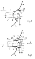
- a tailpipe 2 is held on an exhaust pipe 1 of an exhaust system, not shown, which projects through a cutout 3 of a vehicle rear part 4.
- the cutout is executed all around the tailpipe trim.
- the exhaust end pipe 2 is arranged with a gap distance S1 or S2 in the cutout 3, wherein the gap distance S1 is formed in the cold position I of the exhaust system and the gap distance S2 in a hot position II of the exhaust system or will.
- the tailpipe 2 occurs continuously out of the vehicle rear part 4 and indeed from the position X0 (cold position I) in the position X1 (hot position II).
- a transition region A1 between a first section A2 on the exhaust pipe 1 and a subsequent second section A3, which lies outside of the vehicle rear section 4 is directed to a boundary edge 5 of the vehicle rear section.
- the completely arranged gap S2 in the cutout 3 forms is between the all around extending edge 5 and the transition region A1 and this gap S 2 is substantially greater than the gap S1, whereby a maximum air flow in the direction of arrow P1 possible, so that the existing plastic vehicle rear part 4 no significant heat load essentially by heat radiation, heat conduction experiencing.
- the air duct K formed by the gap S2 is formed by the transition region A1 on the one hand and the edge 5 on the other hand, wherein the transition region A1 rounded concave arc and the edge 5 is drawn inwards and convexly arcuate.
Landscapes
- Engineering & Computer Science (AREA)
- Chemical & Material Sciences (AREA)
- Combustion & Propulsion (AREA)
- Mechanical Engineering (AREA)
- Transportation (AREA)
- General Engineering & Computer Science (AREA)
- Exhaust Silencers (AREA)
- Cooling, Air Intake And Gas Exhaust, And Fuel Tank Arrangements In Propulsion Units (AREA)
- Exhaust-Gas Circulating Devices (AREA)
- Valve Device For Special Equipments (AREA)
- Control Of Throttle Valves Provided In The Intake System Or In The Exhaust System (AREA)
Abstract
Description
- Die Erfindung bezieht sich auf eine Abgasanlage nach dem Oberbegriff des Anspruchs 1.
- Endrohrblenden für Abgasanlagen sind in bekannter Weise am Endrohr der Abgasanlage befestigt und durch einen rundherum laufenden Ausschnitt eines Fahrzeugheckteils hindurchgeführt bzw. schließen mit diesem ab. Aufgrund von relativ starken Eigenbewegungen der Abgasanlage relativ zum Fahrzeugheckteil und einer thermischen Wirkung auf das Fahrzeugheckteil ist ein umlaufender Spalt zum Ausschnitt erforderlich, der diese Bedingungen erfüllt. Dieser Spalt ist relativ groß ausgeführt und deckt gleichermaßen alle Toleranzen aus der Fertigung, Montage sowie den möglichen Schwingbewegungen der Abgasanlage bzw. des Abgasendrohres sowie die auftretenden thermischen Ausdehnungen ab.
- Aufgabe der Erfindung ist es, eine Abgasanlage mit einer Endrohrblende zu schaffen, die einerseits mit einem minimalen Spaltabstand in einem Ausschnitt eines Fahrzeugheckteils angeordnet ist und andererseits im Fahrzustand einen den thermischen Auswirkungen ausreichenden Spaltabstand für die Endrohrblende gewährleistet.
- Diese Aufgabe wird erfindungsgemäß durch die Merkmale des Anspruchs 1 gelöst. Weitere vorteilhafte Merkmale beinhalten die Unteransprüche.
- Die mit der Erfindung hauptsächlich erzielten Vorteile bestehen darin, dass der Spaltabstand für die Endrohrblende im Ausschnitt des Fahrzeugheckteils im kalten Zustand der Abgasanlage die Schwingungsbewegungen sowie Toleranzen aus der Fertigung und Montage berücksichtigt. Insbesondere soll der Spaltabstand in Kaltstellung der Abgasanlage relativ klein ausgeführt sein, aber in einer Warmstellung soll sich ein größerer Spaltabstand zwischen einem Teil der Endrohrblende und dem Ausschnitt ergeben, so dass die thermische Auswirkung auf die Karosseriebauteile vermindert wird.
- Dies wird nach der Erfindung dadurch erzielt, dass die Endrohrblende trompetenförmig mit einem ersten Abschnitt kleinen Durchmesser und einem anschließenden endseitigen zweiten Abschnitt größeren Durchmessers ausgeführt ist. Der zweite Abschnitt weist in einer Kaltstellung der Abgasanlage eine Grundstellung mit einem Spaltabstand zum rundum verlaufenden Ausschnitt auf, der kleiner ist als der sich in einer Warmstellung bei thermischer Längenzunahme der Abgasanlage temporär veränderbare Spaltabstand zwischen der Endrohrblende und dem Ausschnitt. Durch thermische Auswirkungen auf die Abgasanlage im Fahrbetrieb des Kraftfahrzeugs kann sich die Endrohrblende entgegen der Fahrtrichtung aus dem Fahrzeugheckteil herausbewegen, was eine Spaltvergrößerung mit sich bringt und einen Luftdurchsatz durch den Spalt mit einem Abkühlungseffekt mit sich bringt.
- Insbesondere ist nach der Erfindung vorgesehen, dass der erste stromauf des Abgasstromes angeordnete Abschnitt der Endrohrblende dem Durchmesser des Abgasrohres der Abgasanlage angepasst ist und mit diesem verbunden wird, wobei der anschließende Abschnitt über einen konvex bogenförmigen Übergangsbereich mit dem ersten Abschnitt der Endrohrblende verbindbar ist. Es ergibt sich hierdurch in vorteilhafter Weise ein Luftführungskanal mit einem größeren Spalt als in der Kaltstellung der Abgasanlage. In der Kaltstellung der Abgasanlage weist die Endrohrblende einen einer Grundstellung zugeordneten kleinen Spaltabstand im Ausschnitt des Fahrzeugheckteils auf und in der Warmstellung weist die Endrohrblende in einer Endstellung einen größeren Spaltabstand auf.
- Durch den größeren Spaltabstand im Ausschnitt des Fahrzeugheckteils zwischen dem Übergangsbereich der beiden Abschnitte der Endrohrblende werden neben einem ausreichenden Freiraum für Schwingbewegungen im Fahrbetrieb auch die thermischen Auswirkungen auf das Fahrzeugheckteil verringert, das heißt, dass das Fahrzeugheckteil durch die abstrahlende Wärme der Abgasanlage durch den spaltbedingter maximalen Luftdurchsatz nicht zusätzlich belastet wird.
- Ein Ausführungsbeispiel der Erfindung ist in den Zeichnungen dargestellt und wird im Folgenden näher beschrieben.
- Es zeigt
- Fig. 1
- eine schematische Darstellung der Abgasanlage mit Endrohrblende in einer Kaltstellung und
- Fig. 2
- eine schematische Darstellung der Abgasanlage mit Endrohrblende in einer Warmstellung während eines Fahrbetriebs.
- Wie in Fig. 1 näher dargestellt, ist an einem Abgasrohr 1 einer nicht dargestellten Abgasanlage eine Endrohrblende 2 gehalten, das durch einen Ausschnitt 3 eines Fahrzeugheckteils 4 ragt. Der Ausschnitt ist rundherum um die Endrohrblende ausgeführt.
- Das Abgasendrohr 2 ist mit einem Spaltabstand S1 bzw. S2 in dem Ausschnitt 3 angeordnet, wobei der Spaltabstand S1 in Kaltstellung I der Abgasanlage und der Spaltabstand S2 in einer Warmstellung II der Abgasanlage gebildet ist bzw. wird.
- Bei einer direkten Sicht in Pfeilrichtung P von hinten auf die Endrohrblende 2 erscheint nur der Spalt S1, sei es in der Kaltstellung I (Fig. 1) als auch in der Warmstellung II (Fig. 2).
- Bei einer thermischen Erwärmung der Abgasanlage tritt die Endrohrblende 2 kontinuierlich aus dem Fahrzeugheckteil 4 heraus und zwar von der Stellung X0 (Kaltstellung I) in die Stellung X1 (Warmstellung II). Bei dieser thermischen Längenzunahme von X0 zu X1 (Fig. 2) ist ein Übergangsbereich A1 zwischen einem ersten Abschnitt A2 auf dem Abgasrohr 1 und einem anschließenden zweiten Abschnitt A3, der außenliegend des Fahrzeugheckteils 4 liegt, einem Begrenzungsrand 5 des Fahrzeugheckteils zugerichtet. Der rundum angeordnete Spalt S2 im Ausschnitt 3 bildet sich zwischen dem rundherum verlaufenden Rand 5 und dem Übergangsbereich A1 und dieser Spalt S 2 ist wesentlich größer als der Spalt S1, wodurch ein maximaler Luftdurchsatz in Pfeilrichtung P1 möglich, so dass das aus Kunststoff bestehende Fahrzeugheckteil 4 keine wesentliche Wärmebelastung im Wesentlichen durch Wärmestrahlung, Wärmeleitung erfährt.
- Der durch den Spalt S2 gebildete Luftführungskanal K wird durch den Übergangsbereich A1 einerseits und dem Rand 5 andererseits gebildet, wobei der Übergangsbereich A1 konkav bogenförmig ausgerundet und der Rand 5 nach innen eingezogen und konvex bogenförmig ausgeführt ist.
Claims (7)
- Abgasanlage mit einem Abgasendrohr und einer mit diesem verbundenen Endrohrblende, die durch einen Ausschnitt in einem Fahrzeugheckteil ragend angeordnet und mit diesem verbunden ist, dadurch gekennzeichnet, dass die Endrohrblende (2) trompetenförmig mit einem ersten Abschnitt (A2) kleinen Durchmessers (D) und einem anschließenden endseitigen zweiten Abschnitt (A3) größeren Durchmessers (D1) ausgeführt ist und dieser zweite Abschnitt (A3) der Endrohrblende (2) in einer Kaltstellung (I) der Abgasanlage eine Grundstellung mit einem Spaltabstand (S1) zum rundum verlaufenden Ausschnitt (3) aufweist, der kleiner als der sich in einer Warmstellung (II) bei thermischer Längenzunahme der Abgasanlage temporär veränderbare Spaltabstand (S2) zwischen der Endrohrblende (2) und dem Ausschnitt (3) ist.
- Abgasanlage nach Anspruch 1, dadurch gekennzeichnet, dass der stromauf eines Abgasstromes (S) angeordnete erste Abschnitt (A2) kleinen Durchmessers dem Abgasrohr (1) angepasst und mit diesem verbunden ist und ein anschließender konvex bogenförmiger Übergangsbereich (A1) zwischen dem ersten Abschnitt (A2) und dem zweiten Abschnitt (A3) der Endrohrblende (2) angeordnet ist.
- Abgasanlage nach den Ansprüchen 1 oder 2, dadurch gekennzeichnet, dass in der Kaltstellung (I) der Abgasanlage der kleinere Spaltabstand (S1) zwischen dem Ausschnitt (3) im Fahrzeugheckteil (4) und dem zweiten endseitigen Abschnitt (A3) der Endrohrblende (2) besteht.
- Abgasanlage nach den Ansprüchen 1, 2 oder 3, dadurch gekennzeichnet, dass in der Warmstellung (II) der Abgasanlage der größere Spaltabstand (S2) zwischen dem rundum verlaufenden Ausschnitt (3) im Fahrzeugheckteil (4) und dem Übergangsbereich (A1) zwischen den beiden Abschnitte (A2) und A3) der Endrohrblende (2) besteht.
- Abgasanlage nach den Ansprüchen 1, 2, 3 oder 4, dadurch gekennzeichnet, dass der konvex bogenförmige Übergangsbereich (A1) der Endrohrblende (2) zwischen den beiden Abschnitten (A2 und A3) mit dem nach innen eingezogenen Rand (5) des Ausschnitts (3) einen Luftdurchströmkanal (K) mit dem Spaltabstand (S2) ergibt.
- Abgasanlage nach einem der vorhergehenden Ansprüche, dadurch gekennzeichnet, dass in der Kaltstellung (I) der Abgasanlage die Endrohrblende (2) einen in einer Grundstellung (X0) zugeordneten Spaltabstand (S1) im Ausschnitt (3) des Fahrzeugheckteils (4) und in der Warmstellung (II) der Abgasanlage eine Endstellung (X1) mit dem Spaltabstand (S2) aufweist.
- Abgasanlage nach den Ansprüchen 1, 2, 3, 4 oder 5, dadurch gekennzeichnet, dass der Übergangsbereich (A1) durch einen gleichmäßigen Übergangskonus dargestellt ist.
Applications Claiming Priority (1)
| Application Number | Priority Date | Filing Date | Title |
|---|---|---|---|
| DE102006020628A DE102006020628A1 (de) | 2006-05-04 | 2006-05-04 | Abgasanlage |
Publications (2)
| Publication Number | Publication Date |
|---|---|
| EP1852295A1 true EP1852295A1 (de) | 2007-11-07 |
| EP1852295B1 EP1852295B1 (de) | 2008-12-24 |
Family
ID=38329985
Family Applications (1)
| Application Number | Title | Priority Date | Filing Date |
|---|---|---|---|
| EP07004847A Not-in-force EP1852295B1 (de) | 2006-05-04 | 2007-03-09 | Abgasanlage |
Country Status (6)
| Country | Link |
|---|---|
| US (1) | US7604092B2 (de) |
| EP (1) | EP1852295B1 (de) |
| JP (1) | JP4914285B2 (de) |
| CN (1) | CN101311505B (de) |
| AT (1) | ATE418469T1 (de) |
| DE (2) | DE102006020628A1 (de) |
Families Citing this family (12)
| Publication number | Priority date | Publication date | Assignee | Title |
|---|---|---|---|---|
| DE102006020628A1 (de) * | 2006-05-04 | 2007-11-08 | Dr.Ing.H.C. F. Porsche Ag | Abgasanlage |
| KR100962811B1 (ko) * | 2008-04-29 | 2010-06-09 | 기아자동차주식회사 | 자동차용 배기파이프의 테일 트림 제조방법 |
| JP5223510B2 (ja) * | 2008-07-09 | 2013-06-26 | スズキ株式会社 | 車両の排気装置 |
| US20100237607A1 (en) * | 2009-03-18 | 2010-09-23 | Adam Crone | Dual exhaust system |
| CN102294954A (zh) * | 2010-06-28 | 2011-12-28 | 北汽福田汽车股份有限公司 | 汽车 |
| KR101210047B1 (ko) * | 2010-10-08 | 2012-12-10 | 기아자동차주식회사 | 매연흡착방지 타입 테일트림 |
| US9328648B2 (en) * | 2013-04-18 | 2016-05-03 | Ford Global Technologies, Llc | Protective shield to reduce exhaust soot and condensate deposition |
| US9346350B2 (en) * | 2013-04-18 | 2016-05-24 | Ford Global Technologies, Llc | Flush and sub-flush protective shields to reduce exhaust soot and condensate deposition |
| US9536040B2 (en) | 2013-04-18 | 2017-01-03 | Ford Global Technologies, Llc | Methods for designing an exhaust assembly for a vehicle |
| US10801390B2 (en) | 2018-06-28 | 2020-10-13 | Nissan North America, Inc. | Vehicle exhaust system |
| US11319859B2 (en) * | 2019-05-30 | 2022-05-03 | Ford Global Technologies, Llc | Noise attenuating exhaust tail pipe |
| JP7068367B2 (ja) * | 2020-03-16 | 2022-05-16 | フタバ産業株式会社 | テールパイプ |
Citations (4)
| Publication number | Priority date | Publication date | Assignee | Title |
|---|---|---|---|---|
| JPH0396434A (ja) * | 1989-09-08 | 1991-04-22 | Nissan Motor Co Ltd | 自動車のエキゾーストフイニッシャ取付構造 |
| DE19940102A1 (de) * | 1999-08-24 | 2001-03-01 | Magna Pebra Gmbh | Stossfänger mit Auspufföffnung für Automobile |
| DE10136350A1 (de) * | 2001-07-26 | 2003-02-06 | Volkswagen Ag | Abgasleitung für eine Brennkraftmaschine mit einer Endrohrblende |
| EP1582713A1 (de) * | 2004-04-01 | 2005-10-05 | HONDA MOTOR CO., Ltd. | Halteanordnung für eine Kraftfahrzeug-Abgasanlage |
Family Cites Families (37)
| Publication number | Priority date | Publication date | Assignee | Title |
|---|---|---|---|---|
| US2850314A (en) * | 1952-11-17 | 1958-09-02 | Gen Motors Corp | Bumper exhaust |
| US2841348A (en) * | 1953-11-02 | 1958-07-01 | Gen Motors Corp | Exhaust pipe resilient support mount |
| US2841232A (en) * | 1954-11-05 | 1958-07-01 | Gen Motors Corp | Exhaust means extending through accessible enclosures |
| US2992035A (en) * | 1956-01-26 | 1961-07-11 | William J Tell | Exhaust through rear bumper |
| US4323139A (en) * | 1980-10-01 | 1982-04-06 | Baldwin Nealy B | Energy saving exhaust siphon |
| JPS6441617A (en) * | 1987-08-04 | 1989-02-13 | Takashio Giken Kogyo Kk | Exhaust structure of rotary engine |
| JPH01127925A (ja) * | 1987-11-12 | 1989-05-19 | Brother Ind Ltd | 熱電対 |
| US5100047A (en) * | 1988-06-25 | 1992-03-31 | Yukihiro Nakagawa | Spacing ring for tubes in high temperature environment |
| CN2125003U (zh) * | 1992-04-14 | 1992-12-16 | 张洪义 | 改进的内燃机车排气管 |
| JPH07102967A (ja) * | 1993-10-06 | 1995-04-18 | Usui Internatl Ind Co Ltd | 排気管用テールパイプ |
| US5466900A (en) * | 1994-03-04 | 1995-11-14 | Knapp; William | Tail pipe adapter |
| DE19914426C2 (de) * | 1999-03-30 | 2003-04-17 | Daimler Chrysler Ag | Doppelwandiges Endrohr für ein Abgasrohr einer Abgasanlage eines Kraftfahrzeuges |
| JP2001123829A (ja) * | 1999-10-25 | 2001-05-08 | Honda Motor Co Ltd | カバー部材取付構造 |
| US7007720B1 (en) * | 2000-04-04 | 2006-03-07 | Lacks Industries, Inc. | Exhaust tip |
| ATE407841T1 (de) * | 2000-11-07 | 2008-09-15 | Owens Corning Fiberglass Corp | Stossstangen / schalldämpferanordnung |
| JP2003063332A (ja) * | 2001-08-22 | 2003-03-05 | Honda Motor Co Ltd | 燃料電池自動車の排気構造 |
| US7325652B2 (en) * | 2001-11-06 | 2008-02-05 | Ocv Intellectual Capital, Llc | Bumper/muffler assembly |
| FR2835018B1 (fr) * | 2002-01-22 | 2005-09-09 | Hutchinson | Perfectionnement a un flexible de decouplage pour ligne d'echappement d'un moteur de vehicule automobile |
| USD467210S1 (en) * | 2002-05-21 | 2002-12-17 | Wen-Cheng Yu | Tailpipe |
| USD468673S1 (en) * | 2002-05-22 | 2003-01-14 | American Products Company, Inc. | Illuminated tail pipe extension |
| US20030231506A1 (en) * | 2002-06-17 | 2003-12-18 | Hui-Ling Chen | Exhaust pipe with flickering light |
| US20040206573A1 (en) * | 2002-11-27 | 2004-10-21 | Hsu Henry T. H. | Muffler exhaust tip |
| DE10258250A1 (de) * | 2002-12-13 | 2004-07-15 | Dr.Ing.H.C. F. Porsche Ag | Heckverkleidungsteil mit einer daran befestigten Abgasendrohrblende |
| JP2004308551A (ja) * | 2003-04-07 | 2004-11-04 | Honda Motor Co Ltd | 車両における排気管の取付構造 |
| US20050056483A1 (en) * | 2003-09-15 | 2005-03-17 | Hsi-Lung Tsai | Tail pipe for muffler |
| US20050056482A1 (en) * | 2003-09-15 | 2005-03-17 | Hsi-Lung Tsai | Tail pipe for muffler |
| JP2005155440A (ja) * | 2003-11-26 | 2005-06-16 | Mazda Motor Corp | 縦置搭載エンジンの排気系構造 |
| USD534111S1 (en) * | 2004-08-09 | 2006-12-26 | Advanced Car Specialties Limited | Spark arrestor |
| USD523796S1 (en) * | 2005-04-19 | 2006-06-27 | Marques Ricardo H | Exhaust tip |
| US7086224B1 (en) * | 2005-06-08 | 2006-08-08 | Corey Perry | Rotating motor vehicle tail pipe |
| USD539716S1 (en) * | 2005-10-31 | 2007-04-03 | Dr. Ing H.C.F. Porsche Aktiengesellschaft | Exhaust pipe for a vehicle |
| US7942237B2 (en) * | 2006-04-12 | 2011-05-17 | Ocv Intellectual Capital, Llc | Long fiber thermoplastic composite muffler system with integrated reflective chamber |
| DE102006020628A1 (de) * | 2006-05-04 | 2007-11-08 | Dr.Ing.H.C. F. Porsche Ag | Abgasanlage |
| USD560555S1 (en) * | 2006-07-21 | 2008-01-29 | Daimlerchrysler Ag | Vehicle, toy, and/or other replicas |
| USD555063S1 (en) * | 2006-11-27 | 2007-11-13 | Honda Motor Co., Ltd. | Portion of a vehicle exterior |
| USD574309S1 (en) * | 2006-12-22 | 2008-08-05 | Dr. Ing. H.C.F. Porsche Ag | Exhaust pipe |
| USD579841S1 (en) * | 2007-08-30 | 2008-11-04 | Dane Wagner | Exhaust collector |
-
2006
- 2006-05-04 DE DE102006020628A patent/DE102006020628A1/de not_active Ceased
-
2007
- 2007-03-09 DE DE502007000318T patent/DE502007000318D1/de active Active
- 2007-03-09 AT AT07004847T patent/ATE418469T1/de not_active IP Right Cessation
- 2007-03-09 EP EP07004847A patent/EP1852295B1/de not_active Not-in-force
- 2007-04-26 JP JP2007117024A patent/JP4914285B2/ja not_active Expired - Fee Related
- 2007-04-30 CN CN2007101023354A patent/CN101311505B/zh not_active Expired - Fee Related
- 2007-05-04 US US11/800,511 patent/US7604092B2/en not_active Expired - Fee Related
Patent Citations (4)
| Publication number | Priority date | Publication date | Assignee | Title |
|---|---|---|---|---|
| JPH0396434A (ja) * | 1989-09-08 | 1991-04-22 | Nissan Motor Co Ltd | 自動車のエキゾーストフイニッシャ取付構造 |
| DE19940102A1 (de) * | 1999-08-24 | 2001-03-01 | Magna Pebra Gmbh | Stossfänger mit Auspufföffnung für Automobile |
| DE10136350A1 (de) * | 2001-07-26 | 2003-02-06 | Volkswagen Ag | Abgasleitung für eine Brennkraftmaschine mit einer Endrohrblende |
| EP1582713A1 (de) * | 2004-04-01 | 2005-10-05 | HONDA MOTOR CO., Ltd. | Halteanordnung für eine Kraftfahrzeug-Abgasanlage |
Also Published As
| Publication number | Publication date |
|---|---|
| ATE418469T1 (de) | 2009-01-15 |
| EP1852295B1 (de) | 2008-12-24 |
| JP4914285B2 (ja) | 2012-04-11 |
| CN101311505A (zh) | 2008-11-26 |
| JP2007298037A (ja) | 2007-11-15 |
| DE102006020628A1 (de) | 2007-11-08 |
| DE502007000318D1 (de) | 2009-02-05 |
| US7604092B2 (en) | 2009-10-20 |
| US20080093160A1 (en) | 2008-04-24 |
| CN101311505B (zh) | 2010-10-20 |
Similar Documents
| Publication | Publication Date | Title |
|---|---|---|
| EP1852295B1 (de) | Abgasanlage | |
| EP2050600B1 (de) | Entlüftungsvorrichtung | |
| EP1686246B1 (de) | Schalldämpfer für eine Abgasanlage | |
| DE60308895T2 (de) | Fingerförmiges Klappenventil | |
| DE102014118800A1 (de) | Bug eines Kraftfahrzeugs | |
| DE102013107868B4 (de) | Abgaswärme-Rückgewinnungsvorrichtung | |
| DE102008048912B4 (de) | Abgasanlage und Abgasventil zur Steuerung eines Volumenstroms von Abgas sowie ein Verfahren zur Steuerung eines Volumenstroms | |
| DE202014101664U1 (de) | Schutz zur Reduzierung von Abgasruss- und Kondensatablagerung | |
| DE112011101698T5 (de) | Turbolader | |
| DE60310348T2 (de) | Verbesserung zu einem flexiblen Entkopplungsschlauch für eine Auspuffleitung eines Kraftfahrzeugmotors | |
| EP1058033B1 (de) | Nocken für zusammensgesetzte Nockenwelle | |
| EP3137331A1 (de) | Abgasanlage für ein kraftfahrzeug | |
| EP1955886B1 (de) | Kraftfahrzeug | |
| EP1288485A1 (de) | Saugrohr mit Befestigungsflansch und Einsatz zur Verstärkung des Flanschbauteils | |
| DE60218596T2 (de) | Luftfilter und Luftzirkulationssystem für Kraftfahrzeuge mit dem Luftfilter | |
| DE102006022382A1 (de) | Vorrichtung und Verfahren zur Befestigung eines Wischermotors an ein Wischergestänge | |
| DE102008048897A1 (de) | Luftspaltisolierter Abgaskrümmer einer Verbrennungskraftmaschine | |
| DE102018107781A1 (de) | Einlasskrümmer | |
| DE102007020926A1 (de) | Luftansaugkanal | |
| DE102017201719A1 (de) | Vorrichtung zum Vermischen eines Reduktionsmittels mit einem Abgas einer Brennkraftmaschine | |
| DE102017128672A1 (de) | Abschirmung für eine Harnstoffeinspritzvorrichtung | |
| DE60213342T2 (de) | Kraftfahrzeugeinheit mit einer Leitung und einer Innenverkleidung, Verfahren zur Herstellung derselben und Innenverkleidung | |
| DE102005021165B4 (de) | Verkleidungsteil, insbesondere für ein Fahrzeug | |
| DE102014007220A1 (de) | Schlosshalter für einen Kraftfahrzeugtürverschluss | |
| EP3550119B1 (de) | Verbrennungsmotor mit einem entlüftungssystem |
Legal Events
| Date | Code | Title | Description |
|---|---|---|---|
| PUAI | Public reference made under article 153(3) epc to a published international application that has entered the european phase |
Free format text: ORIGINAL CODE: 0009012 |
|
| AK | Designated contracting states |
Kind code of ref document: A1 Designated state(s): AT BE BG CH CY CZ DE DK EE ES FI FR GB GR HU IE IS IT LI LT LU LV MC MT NL PL PT RO SE SI SK TR |
|
| AX | Request for extension of the european patent |
Extension state: AL BA HR MK YU |
|
| RAP1 | Party data changed (applicant data changed or rights of an application transferred) |
Owner name: DR. ING. H.C. F. PORSCHE AKTIENGESELLSCHAFT |
|
| 17P | Request for examination filed |
Effective date: 20080507 |
|
| AKX | Designation fees paid |
Designated state(s): AT DE ES FR GB IT |
|
| RAP1 | Party data changed (applicant data changed or rights of an application transferred) |
Owner name: DR. ING. H.C. F. PORSCHE AKTIENGESELLSCHAFT |
|
| GRAP | Despatch of communication of intention to grant a patent |
Free format text: ORIGINAL CODE: EPIDOSNIGR1 |
|
| GRAS | Grant fee paid |
Free format text: ORIGINAL CODE: EPIDOSNIGR3 |
|
| GRAA | (expected) grant |
Free format text: ORIGINAL CODE: 0009210 |
|
| AK | Designated contracting states |
Kind code of ref document: B1 Designated state(s): AT DE ES FR GB IT |
|
| REG | Reference to a national code |
Ref country code: GB Ref legal event code: FG4D Free format text: NOT ENGLISH |
|
| REF | Corresponds to: |
Ref document number: 502007000318 Country of ref document: DE Date of ref document: 20090205 Kind code of ref document: P |
|
| PG25 | Lapsed in a contracting state [announced via postgrant information from national office to epo] |
Ref country code: ES Free format text: LAPSE BECAUSE OF FAILURE TO SUBMIT A TRANSLATION OF THE DESCRIPTION OR TO PAY THE FEE WITHIN THE PRESCRIBED TIME-LIMIT Effective date: 20090404 |
|
| PLBE | No opposition filed within time limit |
Free format text: ORIGINAL CODE: 0009261 |
|
| STAA | Information on the status of an ep patent application or granted ep patent |
Free format text: STATUS: NO OPPOSITION FILED WITHIN TIME LIMIT |
|
| 26N | No opposition filed |
Effective date: 20090925 |
|
| PG25 | Lapsed in a contracting state [announced via postgrant information from national office to epo] |
Ref country code: AT Free format text: LAPSE BECAUSE OF NON-PAYMENT OF DUE FEES Effective date: 20090309 |
|
| REG | Reference to a national code |
Ref country code: FR Ref legal event code: TP |
|
| REG | Reference to a national code |
Ref country code: GB Ref legal event code: 732E Free format text: REGISTERED BETWEEN 20110310 AND 20110316 |
|
| REG | Reference to a national code |
Ref country code: GB Ref legal event code: 732E Free format text: REGISTERED BETWEEN 20110331 AND 20110406 |
|
| PGFP | Annual fee paid to national office [announced via postgrant information from national office to epo] |
Ref country code: IT Payment date: 20110323 Year of fee payment: 5 |
|
| PGRI | Patent reinstated in contracting state [announced from national office to epo] |
Ref country code: IT Effective date: 20110501 |
|
| PG25 | Lapsed in a contracting state [announced via postgrant information from national office to epo] |
Ref country code: IT Free format text: LAPSE BECAUSE OF NON-PAYMENT OF DUE FEES Effective date: 20120309 |
|
| REG | Reference to a national code |
Ref country code: FR Ref legal event code: PLFP Year of fee payment: 10 |
|
| PGFP | Annual fee paid to national office [announced via postgrant information from national office to epo] |
Ref country code: DE Payment date: 20160223 Year of fee payment: 10 |
|
| PGFP | Annual fee paid to national office [announced via postgrant information from national office to epo] |
Ref country code: FR Payment date: 20160321 Year of fee payment: 10 Ref country code: GB Payment date: 20160321 Year of fee payment: 10 |
|
| REG | Reference to a national code |
Ref country code: DE Ref legal event code: R119 Ref document number: 502007000318 Country of ref document: DE |
|
| GBPC | Gb: european patent ceased through non-payment of renewal fee |
Effective date: 20170309 |
|
| REG | Reference to a national code |
Ref country code: FR Ref legal event code: ST Effective date: 20171130 |
|
| PG25 | Lapsed in a contracting state [announced via postgrant information from national office to epo] |
Ref country code: DE Free format text: LAPSE BECAUSE OF NON-PAYMENT OF DUE FEES Effective date: 20171003 Ref country code: FR Free format text: LAPSE BECAUSE OF NON-PAYMENT OF DUE FEES Effective date: 20170331 |
|
| PG25 | Lapsed in a contracting state [announced via postgrant information from national office to epo] |
Ref country code: GB Free format text: LAPSE BECAUSE OF NON-PAYMENT OF DUE FEES Effective date: 20170309 |