EP1850453B1 - Permanentmagnetrotor - Google Patents
Permanentmagnetrotor Download PDFInfo
- Publication number
- EP1850453B1 EP1850453B1 EP07008288.8A EP07008288A EP1850453B1 EP 1850453 B1 EP1850453 B1 EP 1850453B1 EP 07008288 A EP07008288 A EP 07008288A EP 1850453 B1 EP1850453 B1 EP 1850453B1
- Authority
- EP
- European Patent Office
- Prior art keywords
- permanent magnet
- shaft
- magnet rotor
- rotor according
- fixed bearing
- Prior art date
- Legal status (The legal status is an assumption and is not a legal conclusion. Google has not performed a legal analysis and makes no representation as to the accuracy of the status listed.)
- Not-in-force
Links
Images

Classifications
-
- H—ELECTRICITY
- H02—GENERATION; CONVERSION OR DISTRIBUTION OF ELECTRIC POWER
- H02K—DYNAMO-ELECTRIC MACHINES
- H02K1/00—Details of the magnetic circuit
- H02K1/06—Details of the magnetic circuit characterised by the shape, form or construction
- H02K1/22—Rotating parts of the magnetic circuit
- H02K1/27—Rotor cores with permanent magnets
- H02K1/2706—Inner rotors
- H02K1/272—Inner rotors the magnetisation axis of the magnets being perpendicular to the rotor axis
- H02K1/2726—Inner rotors the magnetisation axis of the magnets being perpendicular to the rotor axis the rotor consisting of a single magnet or two or more axially juxtaposed single magnets
- H02K1/2733—Annular magnets
-
- F—MECHANICAL ENGINEERING; LIGHTING; HEATING; WEAPONS; BLASTING
- F04—POSITIVE - DISPLACEMENT MACHINES FOR LIQUIDS; PUMPS FOR LIQUIDS OR ELASTIC FLUIDS
- F04D—NON-POSITIVE-DISPLACEMENT PUMPS
- F04D13/00—Pumping installations or systems
- F04D13/02—Units comprising pumps and their driving means
- F04D13/06—Units comprising pumps and their driving means the pump being electrically driven
- F04D13/0606—Canned motor pumps
- F04D13/064—Details of the magnetic circuit
-
- H—ELECTRICITY
- H02—GENERATION; CONVERSION OR DISTRIBUTION OF ELECTRIC POWER
- H02K—DYNAMO-ELECTRIC MACHINES
- H02K5/00—Casings; Enclosures; Supports
- H02K5/04—Casings or enclosures characterised by the shape, form or construction thereof
- H02K5/12—Casings or enclosures characterised by the shape, form or construction thereof specially adapted for operating in liquid or gas
- H02K5/128—Casings or enclosures characterised by the shape, form or construction thereof specially adapted for operating in liquid or gas using air-gap sleeves or air-gap discs
-
- H—ELECTRICITY
- H02—GENERATION; CONVERSION OR DISTRIBUTION OF ELECTRIC POWER
- H02K—DYNAMO-ELECTRIC MACHINES
- H02K7/00—Arrangements for handling mechanical energy structurally associated with dynamo-electric machines, e.g. structural association with mechanical driving motors or auxiliary dynamo-electric machines
- H02K7/14—Structural association with mechanical loads, e.g. with hand-held machine tools or fans
Definitions
- the invention relates to a permanent magnet rotor with a shaft, a hollow cylindrical permanent magnet and an elastic connecting means between the shaft and the permanent magnet, wherein the permanent magnet is arranged coaxially around the shaft, the elastic connecting means is arranged over the circumference of the shaft in a plurality of first regions, in which is increased in the distance between the shaft and the permanent magnet, which are defined by second regions, in which the distance between the shaft and the permanent magnet is minimum but not zero.
- the US 5,930,071 describes a drive for a hard disk drive, in which a plurality of components are provided with a layer of an elastomer-like material which is intended to dampen vibration.
- a generic permanent magnet rotor is from the DE 23 28 886 known.
- a hollow cylindrical permanent magnet is fixed by means of an elastic intermediate layer.
- the radial thickness of the elastic intermediate layer is dimensioned such that the permanent magnet can oscillate in the circumferential direction during sudden braking of the motor shaft, thereby damaging a downstream Getritzelitzels be avoided.
- elastic shims are useful to avoid mechanical stress between materials of different thermal expansion.
- the object of the invention is to ensure that the permanent magnet is not unduly deflected from the axis of rotation at high radial load, with a simple and economical assembly method is used and a secure mechanical connection between the shaft and the permanent magnet is guaranteed over the entire life ,
- the object is achieved in that the second regions in which the distance between the shaft and the permanent magnet is minimal, is dimensioned so that a slight expansion of the length of the shaft material relative to the permanent magnet material is possible, but an undesirably large deflection of the permanent magnet in relation is excluded on the shaft or a permanent magnet at a small distance surrounding component and the elastic connecting means (53) in a plurality of axially parallel grooves (511) or in meandering or spiral grooves around the shaft (51) around is arranged.
- the areas with a greater distance serve to securely accommodate the elastic connecting means and the areas with a smaller distance allow only a limited deflection of the permanent magnet with respect to the shaft or to a part surrounding the permanent magnet.
- a shaft (51) is here and below also referred to a rotor body which is integral with the pump impeller and carries the permanent magnet.
- the elastic connecting means (53) is intended to be arranged in several axially parallel grooves (511) or in meandering or spiral grooves around the shaft (51). This can be one or more grooves. It is important that the elastic bonding agent is not applied over the entire surface and that there are no air cushions.
- the elastic connecting means (53) is preferably an elastic adhesive.
- the adhesive establishes a material connection between the shaft (51) and the permanent magnet (52), whereby a permanent intimate connection between the two parts is ensured.
- the number of grooves (511) is not equal to half or equal to the whole number of poles of the permanent magnet.
- the number of grooves (511) is not equal to the number of blades of a pump impeller. By these measures, a minimization of noise is achieved.
- the number of grooves (511) is greater than or equal to three, with three grooves being preferred. It is important that the grooves are evenly spaced around the circumference of the shaft to achieve accurate centering of the shaft with respect to the permanent magnet. "Wings" are synonymous with "shovels”.
- the elastic connecting means should be distributed over the full length of the permanent magnet.
- the proposed magnetic attachment can be used basically in all permanent magnet materials. It is particularly useful to choose this type of connection when using ferrite magnets, because ferrites are particularly brittle and prone to breakage, especially in thermal or other mechanical stresses.
- Electric motors are the most common application for the present invention.
- an undesirably large displacement with respect to a stator (40) is excluded when the ratio (UA) of the air gap length (L) between the permanent magnet rotor (50) and the stator (40) and the minimum distance (A) of the second region (542) between the shaft (51) and the permanent magnet (52) is greater than 1.
- the permanent magnet is deflected only within the permitted limits.
- the permanent magnet rotor (50) has a fixed bearing (54) which is fixed to the axle or rotor.
- the bearing will be rotorfest, so that the bearing surface has a low friction radius.
- the fixed bearing (54) consists of a plastic material that can be processed by injection molding and is joined to the permanent magnet rotor (50) by prototyping.
- the bearing material is connected to the permanent magnet rotor (50) by injection or injection molding. If it is necessary to use a special bearing material, which should not be used for economic or technical reasons for the permanent magnet rotor (50), you use different adapted for the particular purpose plastics. If these aspects are of lesser importance, the same plastic material can also be used for the permanent magnet rotor and the fixed bearing (54) and both can be produced in one operation.
- the fixed bearing (54) may be necessary to form the fixed bearing (54) from a more abrasion-resistant plastic material or from a material with better sliding properties than the shaft material.
- fillers such as graphite.
- Graphite is known as a solid lubricant.
- a two-component injection molding process can be used, wherein the fixed bearing (54) and the shaft are produced in succession in an injection molding tool.
- a particular embodiment of an electric motor includes a permanent magnet, which in addition to a first cooperating with a stator magnetic field radial magnetization a second with a statorfesten Magnetic sensor has cooperating axial magnetization.
- the permanent magnet is integrally formed.
- Electric motors with the permanent magnet rotor (50) according to the invention are particularly suitable for use as pump drives, wherein the shaft (51) cooperates with a pump impeller (59).
- the shaft is integral with the pump impeller.
- the cooling medium is also suitable to cool the pump itself.
- Components to be cooled are the stator, in particular a stator winding or, in the case of electronically commutated direct-current motors, the integrated circuit (IC) for switching the stator winding.
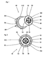
- Fig. 1 shows a three-dimensional representation of a rotor 50 which is mounted on a shaft 49 via a fixed bearing 54.
- the bearing is firmly connected to a shaft 51 designed as a hollow shaft.
- the shaft 51 has four axially parallel grooves 511 on its outer circumference.
- an elastic connecting means 53 is arranged, which establishes a connection between the shaft 51 and a hollow cylindrical permanent magnet 52.
- the Lanyard here is an elastic adhesive, such as silicone.
- the inner diameter of the permanent magnet 52 is slightly larger than the maximum outer diameter of the shaft 51 in the area within the permanent magnet 52.
- the difference in diameter is so dimensioned that on the one hand excess adhesive can dodge into the gap between 51 and 51 permanent magnet, that under external load while a small deviation of the permanent magnet 52 from the center position is possible, but this deviation is limited.
- the adhesive is introduced into the grooves by means of hollow needles.
- the shaft 51 is integral with a pump impeller 59 having wings 591, wherein the wings 591 project from a disc 512.
- the opposite side of the disk 512 serves as a contact surface for the permanent magnet 52.
- a longitudinal groove 58 open to the bearing and to the axis 49 is provided, which serves as a secondary cooling channel.
- Fig. 2 shows an end view of the permanent magnet rotor 50 according to the invention, with the axis 49 which is fixed in a pump housing, the fixed bearing 54, the shaft 51 which is integral with the pump impeller 59.
- the pump impeller is integral with the disc 512 against which the permanent magnet 52 abuts.
- Fig. 3 shows a side view of the erfingungsdorfen permanent magnet rotor 50, with the impeller 59, the wings 591, the disc 512 and the permanent magnet 52, wherein the permanent magnet at an end face region has an axial sensor track magnetization 522 with alternating polarity.
- the permanent magnet has been radially preferential magnetized during its manufacture.
- the axial sensor track magnetization 522 has taken place only after the magnetization of the permanent magnet 52.
- Fig. 4 shows an end view of the pump impeller 59 with the disc 512, the wings 591, the fixed bearing 54 and the longitudinal groove 58th
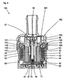
- Fig. 5 shows a sectional view through a centrifugal pump 100 according to the invention, with a pump housing 102, consisting of a first housing part 103 and an adjoining second housing part 104.
- a motor housing part 44 defines a drying space, which is filled by a stator (40) of an electronically commutated DC motor and its control electronics becomes.
- the motor housing part 44 connects to the second housing part 102 and.
- the first and the second housing part 103, 104 define a wet space 101 of the centrifugal pump.
- the second housing part 104 is formed integrally with a containment shell 116 which divides the wet space 101 from a drying space 99.
- the wet room 101 includes an axle 49 which is fixedly installed between a cradle-side axle receptacle 48 and an intake-side axle receptacle 47. A knurling at the axis end prevents rotation of the axis 49 during pump operation.
- a fixed bearing 54 (not shown here) rotatably mounted, which is pressed in a hollow shaft 51 of the rotor 50.
- the shaft 51 is integral with a pump impeller 59 which includes a plurality of approximately spirally shaped wings 591 for the fluid delivery.
- the end faces of the fixed bearing 54 can be supported axially with the interposition of thrust washers against the gap-side axle receptacle 48 and against the intake-side axle receptacle 47.
- a hollow cylindrical ferrite magnet 52 is adhered to the hollow shaft 51, using an elastic adhesive which is inserted into four or five axially parallel grooves 511 (not shown) formed in the hollow shaft.
- the drying chamber 99 contains the stator 40 of the electronically commutated DC motor 10, which is in the form of a hollow cylindrical stator winding 41, the magnetic field is guided in operation via claw poles 42 in an alternating manner to the periphery of the can 116 and the hollow cylindrical permanent magnet 52 in the wet room 101 interacts.
- the magnetic circuit is closed by a return ring 43, which is connected to the claw poles 42.
- the claw poles 42 are provided by encapsulation with an insulating body 46 which connects the claw poles 42 mechanically but not magnetically.
- the stator 40 has four pole pairs in the present example.
- the Isolierstoff Sciences 46 is geometrically shaped so that the winding wires of the stator winding 41 with Klemmschneid brieflye having contact pins 62 are connected, said Klemmschneid brieflye are mechanically fastened in Isolierstoff emotions 46.
- the contact pins 62 are formed as combination contacts and pressed at its end opposite the clamping cutting contact 63 in a printed circuit board 61 and thereby contacted with this.
- the contact pins 62 contain one or two deformable press-fit zones for this purpose.
- the circuit board 61 includes a Hall sensor 71, an integrated circuit 70 for wiring the stator winding, a PTC for the winding protection and plug pins for the power supply.
- the motor housing part 44 includes a connector housing (not shown here) in which the connector pins 64 are arranged.
- Conductor tracks which serve for contacting components to be cooled, are dimensioned such that, for easier heat dissipation, conductor tracks 66 which are as wide as possible are provided on the printed circuit board 61. In order to achieve a particularly good utilization of the printed circuit board 61 and optimum heat dissipation, the different conductor tracks 66 are designed differently wide, depending on how much Heat is generated in the component connection to be contacted.
- a longitudinal groove is formed as a cooling channel between a bottom 117 of the gap pot 116 and the pump impeller 59, which forces a continuous circulation of the fluid also in the interior of the containment shell 116.
- the printed circuit board is arranged between an end face 45 of the motor housing 44 and the bottom 117 of the can 116 and held in heat-conducting contact with the bottom 117 via the heat-conducting film 67.
- the first housing part 103 has a first flange 130 and a first adjoining ring 131.
- the second housing part 104 has a second flange 140 and a second adjoining ring 141.
- the motor housing part has a third ring 441.
- the second flange 140 and the second ring 141 together form a T-shape in cross-section.
- the first sealing region is located on the radially outer side of the first ring 131 on the first housing part 103.
- Opposite on the radially inner side of the second ring 141 and the second housing part 104 is the second sealing region 144.
- Also on the radially inner side the second ring 141 and the second housing part 104 is the third sealing area.
- the second housing part 104 consists of a permeable to laser light of a wavelength or wavelength range material.
- the first housing part 103 and the motor housing part 44 are made of a material absorbing the same laser light. This allows a laser beam without heating the transparent material to a seam lead. There, the beam encounters material that absorbs the light and converts it to heat, causing the plastic to melt and intimately bond with the adjacent material.
- the welding apparatus may comprise two individual lasers, one weld being made with one laser beam at a time, or may comprise a single laser whose output beam is split by a beam splitter into two beams, each of which produces one of the welds.
- the laser beams are directed radially onto the pump housing.
Landscapes
- Engineering & Computer Science (AREA)
- Power Engineering (AREA)
- Mechanical Engineering (AREA)
- General Engineering & Computer Science (AREA)
- Structures Of Non-Positive Displacement Pumps (AREA)
- Permanent Field Magnets Of Synchronous Machinery (AREA)
Description
- Die Erfindung betrifft einen Permanentmagnetrotor mit einer Welle, einem hohlzylindrischen Permanentmagneten und einem elastischem Verbindungsmittel zwischen der Welle und dem Permanentmagneten, wobei der Permanentmagnet koaxial um die Welle herum angeordnet ist, das elastische Verbindungsmittel über den Umfang der Welle in mehreren ersten Bereichen angeordnet ist, in denen der Abstand zwischen der Welle und dem Permanentmagneten vergrößert ist, die von zweiten Bereichen abgegrenzt sind, in denen der Abstand zwischen der Welle und dem Permanentmagneten minimal aber nicht null ist.
- Aus der
US 2004/0045154 A1 ist ein gattungsgemäßer Permanentmagnetrotor bekannt, bei dem das elastische Verbindungsmittel dazu dient Vibrationen und Schwingungen zu dämpfen. Da der Abstand zwischen dem Permanentmagnetring und der Rotorwelle, auch in den Bereichen mit minimalem Abstand, noch groß genug ist, um bei äußeren Stoßbelastungen ein Auslenken des Permanentmagneten gegenüber der Rotorwelle zu bewirken, darf das Material des elastischen Verbindungsmittels nicht zu weich gewählt sein, um noch eine ausreichende Stabilität zu gewährleisten. Deshalb kann keine optimale Dämpfungswirkung erzielt werden. - Die
US 5,930,071 beschreibt einen Antrieb für ein Festplattenlaufwerk, bei dem eine Vielzahl von Bauteilen mit einer Schicht aus einem elastomerähnlichen Material versehen sind, die schwingungsdämpfend wirken soll. - Ein gattungsgemäßer Permanentmagnetrotor ist aus der
DE 23 28 886 bekannt. Hierbei wird ein hohlzylindrischer Permanentmagnet mit Hilfe einer elastischen Zwischenlage befestigt. Die radiale Dicke der elastischen Zwischenlage ist dabei so bemessen, dass der Permanentmagnet beim plötzlichen Abbremsen der Motorwelle in Umfangsrichtung schwingen kann, dadurch soll eine Beschädigung eines nachgeordneten Getrieberitzels vermieden werden. Bei anderen Anwendungen, bei denen große Temperaturschwankungen auftreten können sind elastische Zwischenlagen hilfreich um mechanische Spannungen zwischen Materialien unterschiedlicher Wärmeausdehnung zu vermeiden. Durch eine elastische Zwischenlage allein lässt sich aber eine feste mechanische Verbindung der Welle mit dem Permanentmagneten über die gesamte Lebensdauer nicht zuverlässig sicherstellen. - Ein weiterer Nachteil besteht darin, dass die Rundlaufgenauigkeit bei radialer Belastung nicht ausreichend sein kann, weil das elastische Material nachgiebig ist. Auch darf das Material unter Feuchtigkeitseinfluss nicht quellen. Das Quellen könnte zur Sprengung des Permanentmagneten führen.
- Aufgabe der Erfindung ist es dafür Sorge zu tragen, dass der Permanentmagnet bei großer radialer Belastung nicht unzulässig aus der Drehachse ausgelenkt wird, wobei ein einfaches und wirtschaftliches Montageverfahren verwendet wird und eine sichere mechanische Verbindung zwischen der Welle und dem Permanentmagneten über die gesamte Lebensdauer gewährleistet ist.
- Die Erfindung ist durch die Merkmale der unabhängigen Ansprüche definiert. Die Aufgabe wird erfindungsgemäß dadurch gelöst, dass die zweiten Bereiche, in denen der Abstand zwischen der Welle und dem Permanentmagneten minimal ist, so dimensioniert ist, dass ein geringfügiger Längenausdehnungsausgleich des Wellenmaterials gegenüber dem Permanentmagnetmaterial möglich ist, aber eine unerwünscht große Auslenkung des Permanentmagneten in Bezug auf die Welle oder eines den Permanentmagneten in geringem Abstand umgebenden Bauteils ausgeschlossen wird und das elastische Verbindungsmittel (53) in mehreren achsparallelen Nuten (511) oder in mäanderförmigen oder spiralförmigen Nuten um die Welle (51) herum angeordnet ist. Die Bereiche mit größerem Abstand dienen zur sicheren Aufnahme des elastischen Verbindungsmittels und die Bereiche mit geringerem Abstand lassen nur eine begrenzte Auslenkung des Permanentmagneten in Bezug auf die Welle oder einem den Permanentmagneten umgebenden Teil zu. Dies erhöht die Rundlaufgenauigkeit auch unter erhöhter radialer Belastung. Die Bereiche mit geringerem Abstand können unter Temperatur- oder Druckbelastung oder bei der Montage auftretende Volumenänderungen des elastischen Verbindungsmittels in begrenztem Umfang aufnehmen und dadurch Spannungen im Magnetmaterial vermeiden. Als Welle (51) wird hier und nachfolgend auch ein Rotorkörper bezeichnet, der einstückig mit dem Pumpenlaufrad ist und der den Permanentmagneten trägt. Das elastische Verbindungsmittel (53) soll dabei in mehreren achsparallelen Nuten (511) oder in mäanderförmigen oder spiralförmigen Nuten um die Welle (51) herum angeordnet sein. Dabei kann es sich um ein oder mehrere Nuten handeln. Wichtig ist, dass das elastische Verbindungsmittel nicht vollflächig aufgetragen wird und dass keine Luftkissen entstehen.
- Bevorzugte Ausgestaltungen der Erfindung sind in den abhängigen Ansprüchen definiert.
- Das elastische Verbindungsmittel (53) ist vorzugsweise ein elastischer Klebstoff. Der Klebstoff stellt eine stoffschlüssige Verbindung zwischen der Welle (51) und dem Permanentmagneten (52) her, wodurch eine dauerhafte innige Verbindung zwischen den beiden Teilen sichergestellt ist. Silikon hat sich als geeigneter Klebstoff mit ausreichenden elastischen Eigenschaften herausgestellt. Geignet sind auch RTV-1-Siliconkautschuke der Reihe ELASTOSIL®, die mit der Feuchtigkeit der Luft zu einem elastischen Silicongummi reagieren (RTV-1 = Raum-Temperatur-Vernetzung 1-komponentig).
- Es wird weiter vorgeschlagen dass die Anzahl der Nuten (511) ungleich der halben oder ungleich der ganzen Polzahl des Permanentmagneten ist. Zudem ist es zweckmäßig, dass die Anzahl der Nuten (511) ungleich der Anzahl der Flügel eines Pumpenlaufrades ist. Durch diese Maßnahmen wird eine Minimierung der Geräuschentwicklung erreicht. Um eine stabile Verbindung herzustellen ist es vorteilhaft, dass die Anzahl der Nuten (511) größer oder gleich drei ist, wobei drei Nuten bevorzugt werden. Wichtig ist, dass die Nuten in gleichmäßigen Abständen um den Umfang der Welle verteilt sind, um eine genaue Zentrierung der Welle in Bezug auf den Permanentmagneten zu erreichen. "Flügel" sind gleichbedeutend mit "Schaufeln".
- Damit eine möglichst robuste und mechanisch Stabile Verbindung hergestellt wird sollte sich das elastische Verbindungsmittel über die volle Länge des Permanentmagneten verteilen.
- Die vorgeschlagene Magnetbefestigung kann im Grunde bei allen Permanentmagnet-Werkstoffen eingesetzt werden. Besonders zweckmäßig ist es diese Verbindungsart bei der Verwendung von Ferritmagneten zu wählen, weil Ferrite besonders spröde und bruchanfällig insbesondere bei thermischen oder sonstigen mechanischen Spannungen sind.
- Für eine Vielzahl von Anwendungen ist es wirtschaftlich sinnvoll die Welle aus spritzgusstechnisch verarbeitbarem Kunststoffmaterial herzustellen. Die vorgeschlagene Geometrie der Welle eignet sich für diese Fertigungsart insbesondere wegen der fehlenden Hinterschneidungen, die bei quer angeordneten Nuten unvermeidlich wären.
- Es wird vorgeschlagen die Welle (51) hohl auszubilden und auf einer Achse (49) drehbar zu lagern.
- Elektromotoren sind der häufigste Anwendungsfall für die vorliegende Erfindung. In diesem Fall wird eine unerwünscht große Auslenkung in Bezug auf einen Stator (40) ausgeschlossen, wenn das Verhältnis (UA) der Luftspaltlänge (L) zwischen Permanentmagnetrotor (50) und dem Stator (40) und dem minimalen Abstand (A) des zweiten Bereichs (542) zwischen der Welle (51) und dem Permanentmagneten (52) größer als 1 ist. Auf diese Weise ist der Permanentmagnet nur in innerhalb der erlaubten Grenzen auslenkbar.
- Der Permanentmagnetrotor (50) weist ein Festlager (54) auf, das achsen- oder rotorfest ist. In der Regel wird das Festlager rotorfest sein, damit die Lagerfläche einen geringen Reibradius aufweist.
- In einer bevorzugten Weiterentwicklung des Festlagers (54), besteht dieses aus einem spritzgusstechnisch verarbeitbarem Kunststoffmaterial und ist durch Urformen mit dem Permanentmagnetrotor (50) gefügt. Das Lagermaterial ist in diesem Fall durch Ein- An- oder Umspritzen mit dem Permanentmagnetrotor (50) verbunden. Ist es erforderlich ein spezielles Lagermaterial einzusetzen, das aus wirtschaftlichen oder technischen Gründen nicht für den Permanentmagnetrotor (50) verwendet werden soll, verwendet man unterschiedliche für den jeweiligen Zweck angepasste Kunststoffe. Sind diese Aspekte von untergeordneter Bedeutung kann für den Permanentmagnetrotor und das Festlager (54) auch das gleiche Kunststoffmaterial verwendet werden und beide in einem Arbeitsgang hergestellt werden.
- Es kann erforderlich sein, das Festlager (54) aus einem abriebfesteren Kunststoffmaterial oder aus einem Material mit besseren Gleiteigenschaften auszubilden als das Wellenmaterial. Um die Gleiteigenschaften zu verbessern eignen sich auch Füllstoffe, wie Graphit. Graphit ist als Festschmierstoff bekannt.
- Bei der Verwendung von unterschiedlichen Materialien für das Festlager (54) und für die Welle (51) lässt sich ein Zweikomponenten-Spritzgussverfahren einsetzen, wobei das Festlager (54) und die Welle in einem Spritzgusswerkzeug nacheinander hergestellt werden.
- Eine besondere Ausführungsform eines Elektromotors beinhaltet einen Permanentmagneten, der neben einer ersten mit einem Statormagnetfeld zusammenwirkenden radialen Magnetisierung eine zweite mit einem statorfesten Magnetsensor zusammenwirkende axiale Magnetisierung aufweist. Dabei ist der Permanentmagnet einstückig ausgebildet.
- Elektromotoren mit dem erfindungsgemäßen Permanentmagnetrotor (50) eignen sich insbesondere für den Einsatz als Pumpenantriebe, wobei die Welle (51) mit einem Pumpenlaufrad (59) zusammenwirkt. Bevorzugt ist die Welle einstückig mit dem Pumpenlaufrad. Es ist zwar bekannt den gesamten Pumpenrotor, also Permanentmagnet und Pumpenlaufrad aus einem Material und in einem Arbeitsgang herzustellen, doch auf diese Weise wird mehr Permanentmaterial verbraucht als notwendig wäre. Dies wirkt sich auch auf das Gewicht und das Trägheitsmoment des Pumpenrotors aus. Weiterhin hat sich gezeigt, dass solche einstückigen Pumpenrotoren bei extremen Temperaturschwankungen bersten können, obwohl es sich um kunststoffgebundenes Permanentmaterial handelt.
- Die genannten Temperaturschwankungen treten häufig bei Nassläufer-Kreiselpumpen für Kühlwasserpumpen im Kfz-Bereich auf. Je nach Anwendungsfall ist das Kühlmedium geeignet auch die Pumpe selbst zu kühlen. Zu kühlende Bauteile sind der Stator, insbesondere eine Statorwicklung oder bei elektronisch kommutierten Gleichstrommotoren der integrierte Schaltkreis (IC) für die Umschaltung der Statorwicklung.
- Ein Ausführungsbeispiel der Erfindung wird nachfolgend anhand der Zeichnung näher erläutert. Es zeigen:
-
Fig.1 eine räumliche Darstellung eines Rotors, -
Fig. 2 eine Stirnansicht des Rotors, -
Fig. 3 eine Seitenansicht des Rotors, -
Fig. 4 eine Stirnansicht eines Pumpenlaufrads und -
Fig. 5 eine Zusammenbauzeichnung einer Kreiselpumpe. -
Fig. 1 zeigt eine räumliche Darstellung eines Rotors 50, der über ein Festlager 54 auf einer Achse 49 gelagert ist. Das Lager ist fest mit einer als Hohlwelle ausgebildeten Welle 51 verbunden. Die Welle 51 weist an ihrem Außenumfang vier achsparallele Nuten 511 auf. In den Nuten ist ein elastisches Verbindungsmittel 53 angeordnet, das eine Verbindung zwischen der Welle 51 und einem hohlzylindrischen Permanentmagneten 52 herstellt. Das Verbindungsmittel ist hier ein elastischer Klebstoff, z.B. Silikon. Der Innendurchmesser des Permanentmagneten 52 ist geringfügig größer als der maximale Außendurchmesser der Welle 51 im Bereich innerhalb des Permanentmagneten 52. Der Durchmesserunterschied ist so bemessen, dass einerseits überschüssiger Kleber in den Spalt zwischen Weile 51 und Permanentmagnet 52 ausweichen kann, dass bei äußerer Belastung zwar eine geringe Abweichung des Permanentmagneten 52 aus der Mittenlage möglich ist, diese Abweichung aber eng begrenzt ist. Der Klebstoff wird mit Hilfe von Hohlnadeln in die Nuten eingebracht. Die Welle 51 ist einstückig mit einem Pumpenlaufrad 59, das mit Flügel 591 aufweisen, Wobei die Flügel 591 aus einer Scheibe 512 vorspringen. Die gegenüberliegende Seite der Scheibe 512 dient als Anlagefläche für den Permanentmagneten 52. Auf der Welleninnenseite ist eine zum Lager und zur Achse 49 offene Längsnut 58 vorgesehen, die als sekundärer Kühlkanal dient. -
Fig. 2 zeigt eine Stirnansicht des erfindungsgemäßen Permanentmagnetrotor 50, mit der Achse 49, die in einem Pumpengehäuse befestigt ist, das Festlager 54, die Welle 51, die einstückig mit dem Pumpenlaufrad 59 ist. Das Pumpenlaufrad ist einstückig mit der Scheibe 512, an der der Permanentmagnet 52 anliegt. -
Fig. 3 zeigt eine Seitenansicht des erfingungsgemäßen Permanentmagnetrotors 50, mit dem Pumpenlaufrad 59, den Flügeln 591, der Scheibe 512 und dem Permanentmagneten 52, wobei der Permanentmagnet an einem Stirnseitenbereich eine axiale Sensorspur-Magnetisierung 522 mit alternierender Polung aufweist. Der Permanentmagnet ist bei seiner Herstellung radial vorzugsmagnetisiert worden. Die axiale Sensorspur-Magnetisierung 522 ist erst nach der Magnetisierung des Permanentmagneten 52 erfolgt. -
Fig. 4 zeigt eine Stirnansicht des Pumpenlaufrades 59 mit der Scheibe 512, den Flügeln 591, dem Festlager 54 und der Längsnut 58. -
Fig. 5 zeigt eine Schnittansicht durch eine erfindungsgemäße Kreiselpumpe 100, mit einem Pumpengehäuse 102, bestehend aus einem ersten Gehäuseteil 103 und einem daran anschließenden zweiten Gehäuseteil 104. Ein Motorgehäuseteil 44 begrenzt einen Trockenraum, der von einem Stator (40) eines elektronisch kommutierten Gleichstrommotors und seiner Ansteuerelektronik ausgefüllt wird. Das Motorgehäuseteil 44 schließt an das zweite Gehäuseteil 102 and. Das erste und das zweite Gehäuseteil 103, 104 begrenzen einen Nassraum 101 der Kreiselpumpe. Das zweite Gehäuseteil 104 ist einstückig mit einem Spalttopf 116 geformt, welcher den Nassraum 101 von einem Trockenraum 99. - Der Nassraum 101 enthält eine Achse 49, die zwischen einer spalttopfseitigen Achsaufnahme 48 und einer saugstutzenseitigen Achsaufnahme 47 fest eingebaut ist. Eine Rändelung am Achsenende verhindert eine Verdrehung der Achse 49 während des Pumpenbetriebs. Auf der Achse 49 ist ein Festlager 54 (hier nicht dargestellt) drehbar gelagert, welches in einer hohlen Welle 51 des Rotors 50 eingepresst ist. Die Welle 51 ist einstückig mit einem Pumpenlaufrad 59, das mehrere etwa spiralförmig geformte Flügel 591 für die Flüssigkeitsförderung enthält. Die Stirnflächen des Festlagers 54 können sich axial unter Zwischenlage von Anlaufscheiben gegen die spalttopfseitige Achsaufnahme 48 und gegen die saugstutzenseitige Achsaufnahme 47 abstützen. Ein hohlzylindrischer Ferritmagnet 52 ist auf die hohle Welle 51 aufgeklebt, wobei ein elastischer Kleber verwendet wird, der in vier oder fünf in die Hohlwelle geformte achsparallele Nuten 511 (hier nicht dargestellt) eingebracht ist.
- Der Trockenraum 99 enthält den Stator 40 des elektronisch kommutierten Gleichstrommotors 10, der in Form einer hohlzylindrischen Statorwicklung 41 ausgebildet ist, wobei deren Magnetfeld im Betrieb über Klauenpole 42 in alternierende Weise an den Umfang des Spalttopfs 116 geführt wird und mit dem hohlzylindrsichen Permanentmagneten 52 im Nassraum 101 wechselwirkt. Der magnetische Kreis wird durch einen Rückschlussring 43, der mit den Klauenpolen 42 verbunden ist, geschlossen. Die Klauenpole 42 sind durch Umspritzen mit einem Isolierstoffkörper 46 versehen, der die Klauenpole 42 mechanisch aber nicht magnetisch miteinander verbindet. Der Stator 40 weist im vorliegenden Beispiel vier Polpaare auf. Der Isolierstoffkörper 46 ist geometrisch so geformt, dass die Wicklungsdrähte der Statorwicklung 41 mit Klemmschneidkontakte aufweisende Kontaktpins 62 verbindbar sind, wobei diese Klemmschneidkontakte im Isolierstoffkörper 46 mechanisch befestigbar sind. Die Kontaktpins 62 sind als Kombi-Kontakte geformt und an ihrem dem Klemmschneidkontakt 63 gegenüberliegenden Ende in eine Leiterplatte 61 eingepresst und dadurch mit dieser kontaktiert. Die Kontaktpins 62 enthalten hierfür ein oder zwei verformbare Einpresszonen. Die Leiterplatte 61 enthält einen Hall-Sensor 71, eine integrierte Schaltung 70 für die Beschaltung der Statorwicklung, einen PTC für den Wicklungsschutz und Steckerpins für die Spannungsversorgung. Das Motorgehäuseteil 44 beinhaltet ein Steckergehäuse (hier nicht dargestellt) in welchem die Steckerpins 64 angeordnet sind. Elektronische Bauteile mit großer Verlustwärme werden über Wärmeleitfolien 67 zum Nassraum 101 hin entwärmt. Leiterbahnen, die zur Kontaktierung von zu kühlenden Bauelementen dienen, sind so dimensioniert, dass zur leichteren Wärmeabfuhr möglichst breite Leiterbahnen 66 auf der Leiterplatte 61 vorgesehen sind. Um eine besonders gute Ausnutzung der Leiterplatte 61 und eine optimale Wärmeabfuhr zu erreichen, sind die unterschiedlichen Leiterbahnen 66 unterschiedlich breit ausgeführt, je nach dem wie viel Wärme in dem zu kontaktierenden Bauteileanschluss entsteht. In der Welle 51 ist eine Längsnut als Kühlkanal zwischen einem Boden 117 des Spalttopfs 116 und dem Pumpenlaufrad 59 eingeformt, der eine kontinuierliche Umwälzung des Fördermediums auch im Innenbereich des Spalttopfs 116 erzwingt. Die Leiterplatte ist zwischen einer Stirnseite 45 des Motorgehäuses 44 und dem Boden 117 des Spalttopfs 116 angeordnet und über die Wärmeleitfolie 67 in wärmeleitendem Kontakt mit dem Boden 117 gehalten.
- Das erste Gehäuseteil 103 weist einen ersten Flansch 130 und einen ersten daran anschließenden Ring 131 auf. Das zweite Gehäuseteil 104 weist einen zweiten Flansch 140 und einen zweiten daran anschließenden Ring 141 auf. Das Motorgehäuseteil weist einen dritten Ring 441 auf. Der zweite Flansch 140 und der zweite Ring 141 bilden im Querschnitt zusammen eine T-Form. Es sind vier Dichtungsbereiche vorgesehen. Der erste Dichtungsbereich befindet sich auf der radial außen liegenden Seite des ersten Rings 131 am ersten Gehäuseteil 103. Gegenüberliegend auf der radial innen liegenden Seite des zweiten Rings 141 und des zweiten Gehäuseteils 104 befindet sich der zweite Dichtungsbereich 144. Ebenfalls auf der radial innen liegenden Seite des zweiten Rings 141 und des zweiten Gehäuseteils 104 befindet sich der dritte Dichtungsbereich. Diesem gegenüberliegend auf der radial außen liegenden Seite des dritten Rings 441 und des Motorgehäuseteils 44 befindet sich der vierte Dichtungsbereich. Das zweite Gehäuseteil 104 besteht aus einem für Laserlicht einer Wellenlänge oder eines Wellenlängenbereichs durchlässiges Material. Das erste Gehäuseteil 103 und das Motorgehäuseteil 44 bestehen aus einem dasselbe Laserlicht absorbierendem Material. Dadurch lässt sich ein Laserstrahl ohne Erwärmung des transparenten Materials bis zu einer Nahtstelle führen. Dort trifft der Strahl auf Material, das das Licht absorbiert und in Wärme umwandelt, wodurch der Kunststoff aufschmilzt und eine innige Verbindung mit dem benachbarten Material eingeht.
- Da die beiden zu verschweißenden Dichtungsbereiche nahe beieinander liegen ist es ohne Schwierigkeiten möglich die beiden Nähte in einer Vorrichtung und in einem Arbeitsgang herzustellen. Die Schweißvorrichtung kann zwei einzelne Laser aufweisen, wobei mit jeweils einem Laserstrahl eine Schweißnaht hergestellt wird oder sie kann einen einzigen Laser aufweisen, dessen Ausgangsstrahl durch einen Strahlteiler in zwei Strahlenbündel geteilt wird, von denen jeder eine der Schweißnähte erzeugt. Im vorliegenden Beispiel werden die Laserstrahlen radial auf das Pumpengehäuse gelenkt.
-
- 10
- Elektromotor
- 20
- Luftspalt
- 40
- Stator
- 41
- Statorwicklung
- 42
- Klauenpol
- 420
- ringscheibenförmige Statorbleche
- 421
- Ende
- 422
- Aussparung
- 423
- Steg
- 424
- Luftspalt
- 43
- Rückschlussring
- 430
- Blechbrücke
- 431
- Schlitz
- 432
- Verbindungsschlitz
- 433
- offener Schlitz
- 434
- Freisparung
- 435
- erster Rand
- 436
- zweiter Rand
- 437
- Nahtstelle
- 438
- Verbindungsmittel
- 439
- Blechzunge
- 44
- Motorgehäuse
- 45
- Stirnseite (des Motorgehäuses)
- 46
- Isolierstoffkörper
- 461
- Aufnahmeschlitz
- 462
- Montageausnehmung
- 463
- Befestigungsmittel
- 464
- Anschlag
- 465
- Schnappmittel
- 466
- Vorsprung
- 467
- Halterung (für Steckerpin)
- 47
- saugstutzenseitige Achsaufnahme
- 48
- spalttopfseitige Achsaufnahme
- 49
- Achse
- 50
- Rotor
- 51
- Welle
- 511
- Nut
- 512
- Scheibe
- 52
- hohlzylindrischer Permanentmagnet
- 521
- Arbeitsmagnetisierung
- 522
- Sensorspur-Magnetisierung
- 523
- Stirnseite (des Permanentmagneten)
- 524
- Sicherheitsspalt
- 53
- elastisches Verbindungsmittel
- 531
- erster Bereich (breit)
- 532
- zweiter Bereich (schmal)
- 54
- Festlager
- 58
- Längsnut (für sekundären Flüssigkeitskreislauf)
- 59
- Pumpenlaufrad
- 591
- Flügel
- 60
- Elektronik
- 61
- Leiterplatte
- 611
- Ausnehmungen
- 62
- Kontaktpin
- 63
- Klemmschneidkontakt
- 64
- Steckerpin
- 641
- Anformungen
- 65
- Steckergehäuse
- 66
- Leiterbahn
- 67
- Wärmeleitfolie
- 70
- Integrierter Schaltkreis (IC)
- 71
- Hall-Sensor
- 99
- Trockenraum
- 100
- Kreiselpumpe
- 101
- Nassraum
- 102
- Pumpengehäuse
- 103
- erstes Gehäuseteil
- 104
- zweites Gehäuseteil
- 105
- Saugstutzen
- 106
- Druckstutzen
- 109
- Pumpenraum
- 111
- runde Kontur
- 112
- Sporn
- 113
- Übergangsbereich
- 114
- Umfangswandung
- 115
- scharfe Kante
- 116
- Spalttopf
- 117
- Boden
- 118
- Rotorraum
- 119
- Vertiefung
- 120
- spiralförmige Innenkontur
- 121
- Aufnahme
- 122
- Pumpenbefestigungsmittel
- 123
- Verrundung
- 130
- erster Flansch
- 131
- erster Ring
- 133
- erster Dichtungsbereich
- 140
- zweiter Flansch
- 141
- zweiter Ring
- 144
- zweiter Dichtungsbereich
- 145
- dritter Dichtungsbereich
- 150
- Schwalbenschwanzkontur
- 151
- komplementäre Kontur
- 152
- V-förmige Ausnehmung
- 441
- dritter Ring
- 444
- vierter Dichtungsbereich
Claims (25)
- Permanentmagnetrotor (50) mit einer Welle (51), einem hohlzylindrischen Permanentmagneten (52) und einem elastischem Verbindungsmittel (53) zwischen der Welle (51) und dem Permanentmagneten (52), wobei der Permanentmagnet (52) koaxial um die Welle (51) herum angeordnet ist, das elastische Verbindungsmittel (53) über den Umfang der Welle in mehreren ersten Bereichen angeordnet ist, in denen der Abstand zwischen der Welle (51) und dem Permanentmagneten (52) vergrößert ist, die von zweiten Bereichen abgegrenzt sind, in denen der Abstand zwischen der Welle (51) und dem Permanentmagneten (52) minimal aber nicht null ist, dadurch gekennzeichnet, dass die zweiten Bereiche, in denen der Abstand zwischen der Welle (51) und dem Permanentmagneten (52) minimal ist, so dimensioniert ist, dass ein geringfügiger Längenausdehnungsausgleich des Wellenmaterials gegenüber dem Permanentmagnetmaterial möglich ist, aber eine unerwünscht große Auslenkung des Permanentmagneten (52) in Bezug auf die Welle oder eines den Permanentmagneten in geringem Abstand umgebenden Bauteils ausgeschlossen wird und das elastische Verbindungsmittel (53) in mehreren achsparallelen Nuten (511) oder in mäanderförmigen oder spiralförmigen Nuten um die Welle (51) herum angeordnet ist.
- Permanentmagnetrotor nach Anspruch 1, dadurch gekennzeichnet, dass das Verbindungsmittel (53) ein elastischer Klebstoff ist.
- Permanentmagnetrotor nach Anspruch 2, dadurch gekennzeichnet, dass der Klebstoff Silikon enthält oder aus Silikon besteht.
- Permanentmagnetrotor nach Anspruch 3, dadurch gekennzeichnet, dass die Anzahl der Nuten (511) ungleich der halben oder ungleich der ganzen Polzahl des Permanentmagneten ist.
- Permanentmagnetrotor nach Anspruch 3 oder 4, dadurch gekennzeichnet, dass die Anzahl der Nuten (511) ungleich der Anzahl der Flügel (591) eines Pumpenlaufrades ist.
- Permanentmagnetrotor nach Anspruch 3, 4 oder 5, dadurch gekennzeichnet, dass die Anzahl der Nuten (511) größer oder gleich drei ist.
- Permanentmagnetrotor nach Anspruch 3, 4, 5 oder 6, dadurch gekennzeichnet, dass die Nuten in gleichmäßigen Abständen über den Umfang der Welle (51) verteilt sind.
- Permanentmagnetrotor nach zumindest einem der vorangehenden Ansprüche, dadurch gekennzeichnet, dass das elastische Verbindungsmittel (53) über die volle Länge des Permanentmagneten (52) verteilt ist.
- Permanentmagnetrotor nach zumindest einem der vorangehenden Ansprüche, dadurch gekennzeichnet, dass der Permanentmagnet ein Ferritmagnet ist.
- Permanentmagnetrotor nach zumindest einem der vorangehenden Ansprüche, dadurch gekennzeichnet, dass die Welle aus spritzgusstechnisch verarbeitbarem Kunststoffmaterial besteht.
- Permanentmagnetrotor nach zumindest einem der vorangehenden Ansprüche, dadurch gekennzeichnet, dass die Welle (51) eine Hohlwelle ist, die auf einer Achse (49) drehbar gelagert ist.
- Permanentmagnetrotor nach zumindest einem der vorangehenden Ansprüche, dadurch gekennzeichnet, dass der Permanentmagnetrotor (50) mit einem Festlager (54) drehfest ist.
- Permanentmagnetrotor nach Anspruch 12, dadurch gekennzeichnet, dass das Festlager (54) aus einem spritzgusstechnisch verarbeitbarem Kunststoffmaterial besteht und durch Urformen mit dem Permanentmagnetrotor (50) gefügt ist.
- Permanentmagnetrotor nach Anspruch 12 oder 13, dadurch gekennzeichnet, dass das Festlager (54) und eine Welle (51) des Permanentmagnetrotors (50) aus dem gleichen oder unterschiedlichem Material bestehen.
- Permanentmagnetrotor nach Anspruch 13 oder 14, dadurch gekennzeichnet, dass das Festlager (54) aus einem abriebfesteren Kunststoffmaterial besteht, als die Welle (51).
- Permanentmagnetrotor nach Anspruch 13, 14 oder 15, dadurch gekennzeichnet, dass das Festlager (54) mit Füllstoffen versehen ist, das die Gleitfähigkeit der Lagerung verbessert.
- Permanentmagnetrotor nach Anspruch 16, dadurch gekennzeichnet, dass Graphit als Füllstoff dient.
- Permanentmagnetrotor nach zumindest einem der Ansprüche 12 bis 17, dadurch gekennzeichnet, dass das Festlager (54) und die Welle (51) in einem Zweikomponenten-Spritzgussverfahren hergestellt ist, wobei das Festlager (54) und die Welle aus unterschiedlichen Kunststoffkomponenten bestehen.
- Elektromotor (10) mit einem bewickelten Stator (40) und dem Permanentmagnetrotor (52) nach zumindest einem der vorangehenden Ansprüche
- Elektromotor nach Anspruch 19, dadurch gekennzeichnet, dass das Verhältnis (UA) der Luftspaltlänge (L) zwischen Permanentmagnetrotor (50) und dem Stator (40) und dem minimalen Abstand (A) des zweiten Bereichs (532) zwischen der Welle (51) und dem Permanentmagneten (52) größer als 1 ist.
- Elektromotor nach Anspruch 1 oder 19, dadurch gekennzeichnet, dass der Permanentmagnet (52) eine erste radiale Magnetisierung, dessen Magnetfeld mit einem Statormagnetfeld zusammenwirkt und eine zweite axiale Magnetisierung die mit einem statorfesten Magnetsensor zusammenwirkt, aufweist.
- Kreiselpumpe (100) mit einem Elektromotor (10) nach Anspruch 1, 19 oder 20, dadurch gekennzeichnet, dass die Welle (51) mit einem Pumpenlaufrad (59) zusammenwirkt.
- Kreiselpumpe nach Anspruch 22, dadurch gekennzeichnet, dass die Welle (51) mit dem Pumpenlaufrad (59) einstückig ist.
- Kreiselpumpe nach Anspruch 22 oder 23, dadurch gekennzeichnet, dass die Kreiselpumpe eine Nassläuferpumpe (100) ist.
- Kreiselpumpe nach Anspruch 22, 23 oder 24, dadurch gekennzeichnet, dass zwischen der Achse und der Welle (51) eine Längsnut (58) angeordnet ist die als Kanal für einen sekundären Flüssigkeitskreislauf zur Kühlung von elektronischen Bauteilen oder einer Statorwicklung (41) dient.
Applications Claiming Priority (1)
| Application Number | Priority Date | Filing Date | Title |
|---|---|---|---|
| DE102006021244A DE102006021244A1 (de) | 2006-04-28 | 2006-04-28 | Permanentmagnetrotor |
Publications (2)
| Publication Number | Publication Date |
|---|---|
| EP1850453A1 EP1850453A1 (de) | 2007-10-31 |
| EP1850453B1 true EP1850453B1 (de) | 2013-09-18 |
Family
ID=38371078
Family Applications (1)
| Application Number | Title | Priority Date | Filing Date |
|---|---|---|---|
| EP07008288.8A Not-in-force EP1850453B1 (de) | 2006-04-28 | 2007-04-24 | Permanentmagnetrotor |
Country Status (3)
| Country | Link |
|---|---|
| US (1) | US7573169B2 (de) |
| EP (1) | EP1850453B1 (de) |
| DE (1) | DE102006021244A1 (de) |
Families Citing this family (28)
| Publication number | Priority date | Publication date | Assignee | Title |
|---|---|---|---|---|
| EP2072826B1 (de) * | 2007-12-17 | 2015-10-14 | Grundfos Management A/S | Rotor für einem Spaltrohrmotor |
| DE102009028310A1 (de) | 2009-08-06 | 2011-02-10 | Robert Bosch Gmbh | Flüssigkeitspumpe |
| KR101490901B1 (ko) * | 2009-11-19 | 2015-02-09 | 현대자동차 주식회사 | 전기식 워터 펌프 |
| CN117045914A (zh) | 2011-07-13 | 2023-11-14 | 费雪派克医疗保健有限公司 | 加压气体源 |
| US10137264B2 (en) * | 2011-07-13 | 2018-11-27 | Fisher & Paykel Healthcare Limited | Respiratory assistance apparatus |
| DE102011079225A1 (de) | 2011-07-15 | 2013-01-17 | Bühler Motor GmbH | Flüssigkeitspumpe, insbesondere Wasserpumpe |
| DE102011079226B4 (de) | 2011-07-15 | 2014-12-24 | Bühler Motor GmbH | Flüssigkeitspumpe, insbesondere Wasserpumpe |
| DE102011079224B3 (de) * | 2011-07-15 | 2012-12-06 | Bühler Motor GmbH | Kreiselpumpenlaufrad einer durch einen elektronisch kommutierten Gleichstrommotor angetriebenen Kreiselpumpe |
| DE102011113876B4 (de) * | 2011-09-22 | 2014-01-16 | Sew-Eurodrive Gmbh & Co Kg | Anordnung mit einer Welle-Nabe-Verbindung und Verfahren zum Klebeverbinden einer Nabe mit einer Welle |
| DE102011054955B4 (de) | 2011-10-31 | 2025-10-02 | Minebea Mitsumi Inc. | Rotorbaugruppe eines Gleichstrommotors |
| US8920136B2 (en) | 2012-01-11 | 2014-12-30 | Hamilton Sundstrand Corporation | Seal arrangement for turbomachine |
| US8920142B2 (en) * | 2012-02-28 | 2014-12-30 | Hamilton Sundstrand Corporation | Wet rotor pump motor stator sealing liner |
| AU2013101734A4 (en) | 2012-12-18 | 2015-09-24 | Fisher & Paykel Healthcare Limited | Impeller and motor assembly |
| EP2779364A1 (de) * | 2013-03-14 | 2014-09-17 | Selni | Elektronisch gesteuerter Motor mit Permanentmagnetrotor |
| CN106208516B (zh) * | 2015-04-30 | 2019-11-05 | 浙江三花汽车零部件有限公司 | 转子组件以及电驱动泵 |
| DE102016202417A1 (de) * | 2016-02-17 | 2017-08-17 | Bühler Motor GmbH | Kreiselpumpe |
| US20210048028A1 (en) * | 2016-04-14 | 2021-02-18 | Bingyan YU | Water pump motor and water pump |
| WO2018027895A1 (zh) * | 2016-08-12 | 2018-02-15 | 深圳智慧能源技术有限公司 | 管轴式一体化永磁电机转子 |
| CN106230188B (zh) * | 2016-08-29 | 2018-11-30 | 新昌县鼎瑞科技有限公司 | 一种使用寿命长的防爆电机 |
| DE102017204423A1 (de) | 2017-03-16 | 2018-09-20 | Robert Bosch Gmbh | Wischerantrieb |
| WO2018199774A1 (en) | 2017-04-23 | 2018-11-01 | Fisher & Paykel Healthcare Limited | Breathing assistance apparatus |
| DE102018201841B3 (de) * | 2018-02-06 | 2019-05-29 | Bühler Motor GmbH | Pumpenlaufrad, Verfahren zur Herstellung eines Pumpenlaufrads und Pumpe mit dem Pumpenlaufrad |
| US20200325900A1 (en) * | 2019-04-10 | 2020-10-15 | Hanon Systems EFP Canada Ltd. | External Rotor Electric Pump |
| US11519415B2 (en) | 2020-04-02 | 2022-12-06 | Hanon Systems EFP Canada Ltd. | Automotive accessory having an electromagnet pulley assist mechanism equipped with circumferentially spaced teeth nested with a conductive body |
| CN112983880B (zh) * | 2021-02-24 | 2022-07-05 | 重庆上方汽车配件有限责任公司 | 一种贯流风扇驱动轴连接装置 |
| JP7733478B2 (ja) * | 2021-05-31 | 2025-09-03 | ニデックインスツルメンツ株式会社 | ポンプ装置 |
| DE102021131017B4 (de) | 2021-11-25 | 2025-02-06 | Bühler Motor GmbH | Flüssigkeitspumpe mit optimierter Kühlung und Wärmeableitung |
| DE102023107989A1 (de) * | 2023-03-29 | 2024-10-02 | Bühler Motor GmbH | Permanentmagnetrotor |
Family Cites Families (12)
| Publication number | Priority date | Publication date | Assignee | Title |
|---|---|---|---|---|
| DE2328886B2 (de) | 1973-06-06 | 1977-12-29 | Siemens AG, 1000 Berlin und 8000 München | Mit einem getriebe gekuppelter gleichstromkleinmotor |
| JPS56157249A (en) * | 1980-05-09 | 1981-12-04 | Hitachi Ltd | Magnet rotor |
| DE3308946A1 (de) * | 1983-03-12 | 1984-09-13 | Max Baermann GmbH, 5060 Bergisch Gladbach | Kunststoffgebundener, dauermagnetischer rotor hohlzylindrischer bzw. topffoermiger gestalt fuer elektrische maschinen, insbesondere kleinmotoren |
| JP3364960B2 (ja) * | 1992-09-04 | 2003-01-08 | 松下電器産業株式会社 | 永久磁石電動機の回転子 |
| JPH0775269A (ja) * | 1993-08-31 | 1995-03-17 | Matsushita Electric Ind Co Ltd | 永久磁石電動機の回転子 |
| JPH0865932A (ja) * | 1994-08-25 | 1996-03-08 | Japan Servo Co Ltd | 永久磁石式回転子 |
| JPH08154351A (ja) * | 1994-11-29 | 1996-06-11 | Daido Steel Co Ltd | マグネットロータ |
| WO1996036968A1 (en) | 1995-05-19 | 1996-11-21 | Rubber-Tech, Inc. | Disk drive assembly with vibration dampening characteristics |
| BR9702802A (pt) * | 1997-08-28 | 2000-02-15 | Brasil Compressores Sa | Rotor para motor elétrico. |
| JP2001268831A (ja) * | 2000-03-21 | 2001-09-28 | Matsushita Electric Ind Co Ltd | 永久磁石ロータ |
| JP2001327105A (ja) | 2000-05-17 | 2001-11-22 | Fujitsu General Ltd | 電動機の回転子およびその製造方法 |
| JP4369377B2 (ja) * | 2005-02-04 | 2009-11-18 | 三菱電機株式会社 | 回転電機 |
-
2006
- 2006-04-28 DE DE102006021244A patent/DE102006021244A1/de not_active Withdrawn
-
2007
- 2007-04-24 EP EP07008288.8A patent/EP1850453B1/de not_active Not-in-force
- 2007-04-27 US US11/790,815 patent/US7573169B2/en not_active Expired - Fee Related
Also Published As
| Publication number | Publication date |
|---|---|
| EP1850453A1 (de) | 2007-10-31 |
| US20070284952A1 (en) | 2007-12-13 |
| DE102006021244A1 (de) | 2007-11-08 |
| US7573169B2 (en) | 2009-08-11 |
Similar Documents
| Publication | Publication Date | Title |
|---|---|---|
| EP1850453A1 (de) | Permanentmagnetrotor | |
| EP1850014B1 (de) | Kreiselpumpe | |
| DE102010044453B4 (de) | Bürstenloser Motor | |
| DE102006021242B4 (de) | Elektromotor | |
| EP2398130B1 (de) | Elektrokleinmotor | |
| EP4035253A1 (de) | Axialflussmaschine | |
| EP3899284B1 (de) | Seitenkanalverdichter für ein brennstoffzellensystem zur förderung und/oder verdichtung eines gasförmigen mediums | |
| EP1850015A2 (de) | Kreiselpumpe | |
| EP1850448A1 (de) | Elektromotor | |
| DE102011079226B4 (de) | Flüssigkeitspumpe, insbesondere Wasserpumpe | |
| EP1256722A2 (de) | Kreiselpumpe | |
| DE102014226047A1 (de) | Speichenrotor mit Umspritzung | |
| EP2899404A1 (de) | Kreiselpumpenlaufrad | |
| DE102013200655B4 (de) | Kombiniertes Radial-Axiallager und Nassläuferpumpe | |
| EP4483477A1 (de) | Bürstenloser motor sowie verfahren zur montage eines bürstenlosen motors | |
| DE3326543A1 (de) | Aussenlaeufermotor fuer eine ventilator | |
| EP1850449A2 (de) | Elektromotor | |
| EP3391509B1 (de) | Elektromotor | |
| DE102007037842A1 (de) | Elektrische Maschine | |
| WO2025098564A1 (de) | Rotoranordnung und elektrische maschine | |
| DE102014108366A1 (de) | "Modularer Hohlwellenmotor" | |
| DE102011079225A1 (de) | Flüssigkeitspumpe, insbesondere Wasserpumpe | |
| DE102018201841B3 (de) | Pumpenlaufrad, Verfahren zur Herstellung eines Pumpenlaufrads und Pumpe mit dem Pumpenlaufrad | |
| DE102023130902B4 (de) | Rotoranordnung und elektrische Maschine | |
| WO2025098565A1 (de) | Rotoranordnung und elektrische maschine |
Legal Events
| Date | Code | Title | Description |
|---|---|---|---|
| PUAI | Public reference made under article 153(3) epc to a published international application that has entered the european phase |
Free format text: ORIGINAL CODE: 0009012 |
|
| AK | Designated contracting states |
Kind code of ref document: A1 Designated state(s): AT BE BG CH CY CZ DE DK EE ES FI FR GB GR HU IE IS IT LI LT LU LV MC MT NL PL PT RO SE SI SK TR |
|
| AX | Request for extension of the european patent |
Extension state: AL BA HR MK YU |
|
| 17P | Request for examination filed |
Effective date: 20080219 |
|
| 17Q | First examination report despatched |
Effective date: 20080320 |
|
| AKX | Designation fees paid |
Designated state(s): AT BE BG CH CY CZ DE DK EE ES FI FR GB GR HU IE IS IT LI LT LU LV MC MT NL PL PT RO SE SI SK TR |
|
| GRAP | Despatch of communication of intention to grant a patent |
Free format text: ORIGINAL CODE: EPIDOSNIGR1 |
|
| INTG | Intention to grant announced |
Effective date: 20130416 |
|
| GRAS | Grant fee paid |
Free format text: ORIGINAL CODE: EPIDOSNIGR3 |
|
| GRAA | (expected) grant |
Free format text: ORIGINAL CODE: 0009210 |
|
| AK | Designated contracting states |
Kind code of ref document: B1 Designated state(s): AT BE BG CH CY CZ DE DK EE ES FI FR GB GR HU IE IS IT LI LT LU LV MC MT NL PL PT RO SE SI SK TR |
|
| REG | Reference to a national code |
Ref country code: GB Ref legal event code: FG4D Free format text: NOT ENGLISH |
|
| REG | Reference to a national code |
Ref country code: CH Ref legal event code: EP |
|
| REG | Reference to a national code |
Ref country code: IE Ref legal event code: FG4D Free format text: LANGUAGE OF EP DOCUMENT: GERMAN |
|
| REG | Reference to a national code |
Ref country code: AT Ref legal event code: REF Ref document number: 633218 Country of ref document: AT Kind code of ref document: T Effective date: 20131015 |
|
| REG | Reference to a national code |
Ref country code: DE Ref legal event code: R096 Ref document number: 502007012292 Country of ref document: DE Effective date: 20131114 |
|
| PG25 | Lapsed in a contracting state [announced via postgrant information from national office to epo] |
Ref country code: LT Free format text: LAPSE BECAUSE OF FAILURE TO SUBMIT A TRANSLATION OF THE DESCRIPTION OR TO PAY THE FEE WITHIN THE PRESCRIBED TIME-LIMIT Effective date: 20130918 Ref country code: SE Free format text: LAPSE BECAUSE OF FAILURE TO SUBMIT A TRANSLATION OF THE DESCRIPTION OR TO PAY THE FEE WITHIN THE PRESCRIBED TIME-LIMIT Effective date: 20130918 Ref country code: CY Free format text: LAPSE BECAUSE OF FAILURE TO SUBMIT A TRANSLATION OF THE DESCRIPTION OR TO PAY THE FEE WITHIN THE PRESCRIBED TIME-LIMIT Effective date: 20130703 |
|
| REG | Reference to a national code |
Ref country code: NL Ref legal event code: VDEP Effective date: 20130918 |
|
| REG | Reference to a national code |
Ref country code: LT Ref legal event code: MG4D |
|
| PG25 | Lapsed in a contracting state [announced via postgrant information from national office to epo] |
Ref country code: LV Free format text: LAPSE BECAUSE OF FAILURE TO SUBMIT A TRANSLATION OF THE DESCRIPTION OR TO PAY THE FEE WITHIN THE PRESCRIBED TIME-LIMIT Effective date: 20130918 Ref country code: GR Free format text: LAPSE BECAUSE OF FAILURE TO SUBMIT A TRANSLATION OF THE DESCRIPTION OR TO PAY THE FEE WITHIN THE PRESCRIBED TIME-LIMIT Effective date: 20131219 Ref country code: FI Free format text: LAPSE BECAUSE OF FAILURE TO SUBMIT A TRANSLATION OF THE DESCRIPTION OR TO PAY THE FEE WITHIN THE PRESCRIBED TIME-LIMIT Effective date: 20130918 Ref country code: SI Free format text: LAPSE BECAUSE OF FAILURE TO SUBMIT A TRANSLATION OF THE DESCRIPTION OR TO PAY THE FEE WITHIN THE PRESCRIBED TIME-LIMIT Effective date: 20130918 |
|
| PG25 | Lapsed in a contracting state [announced via postgrant information from national office to epo] |
Ref country code: CY Free format text: LAPSE BECAUSE OF FAILURE TO SUBMIT A TRANSLATION OF THE DESCRIPTION OR TO PAY THE FEE WITHIN THE PRESCRIBED TIME-LIMIT Effective date: 20130918 |
|
| PG25 | Lapsed in a contracting state [announced via postgrant information from national office to epo] |
Ref country code: IS Free format text: LAPSE BECAUSE OF FAILURE TO SUBMIT A TRANSLATION OF THE DESCRIPTION OR TO PAY THE FEE WITHIN THE PRESCRIBED TIME-LIMIT Effective date: 20140118 Ref country code: SK Free format text: LAPSE BECAUSE OF FAILURE TO SUBMIT A TRANSLATION OF THE DESCRIPTION OR TO PAY THE FEE WITHIN THE PRESCRIBED TIME-LIMIT Effective date: 20130918 Ref country code: CZ Free format text: LAPSE BECAUSE OF FAILURE TO SUBMIT A TRANSLATION OF THE DESCRIPTION OR TO PAY THE FEE WITHIN THE PRESCRIBED TIME-LIMIT Effective date: 20130918 Ref country code: EE Free format text: LAPSE BECAUSE OF FAILURE TO SUBMIT A TRANSLATION OF THE DESCRIPTION OR TO PAY THE FEE WITHIN THE PRESCRIBED TIME-LIMIT Effective date: 20130918 Ref country code: RO Free format text: LAPSE BECAUSE OF FAILURE TO SUBMIT A TRANSLATION OF THE DESCRIPTION OR TO PAY THE FEE WITHIN THE PRESCRIBED TIME-LIMIT Effective date: 20130918 Ref country code: NL Free format text: LAPSE BECAUSE OF FAILURE TO SUBMIT A TRANSLATION OF THE DESCRIPTION OR TO PAY THE FEE WITHIN THE PRESCRIBED TIME-LIMIT Effective date: 20130918 |
|
| PG25 | Lapsed in a contracting state [announced via postgrant information from national office to epo] |
Ref country code: ES Free format text: LAPSE BECAUSE OF FAILURE TO SUBMIT A TRANSLATION OF THE DESCRIPTION OR TO PAY THE FEE WITHIN THE PRESCRIBED TIME-LIMIT Effective date: 20130918 Ref country code: PL Free format text: LAPSE BECAUSE OF FAILURE TO SUBMIT A TRANSLATION OF THE DESCRIPTION OR TO PAY THE FEE WITHIN THE PRESCRIBED TIME-LIMIT Effective date: 20130918 |
|
| REG | Reference to a national code |
Ref country code: DE Ref legal event code: R097 Ref document number: 502007012292 Country of ref document: DE |
|
| PG25 | Lapsed in a contracting state [announced via postgrant information from national office to epo] |
Ref country code: PT Free format text: LAPSE BECAUSE OF FAILURE TO SUBMIT A TRANSLATION OF THE DESCRIPTION OR TO PAY THE FEE WITHIN THE PRESCRIBED TIME-LIMIT Effective date: 20140120 |
|
| PLBE | No opposition filed within time limit |
Free format text: ORIGINAL CODE: 0009261 |
|
| STAA | Information on the status of an ep patent application or granted ep patent |
Free format text: STATUS: NO OPPOSITION FILED WITHIN TIME LIMIT |
|
| 26N | No opposition filed |
Effective date: 20140619 |
|
| PG25 | Lapsed in a contracting state [announced via postgrant information from national office to epo] |
Ref country code: IT Free format text: LAPSE BECAUSE OF FAILURE TO SUBMIT A TRANSLATION OF THE DESCRIPTION OR TO PAY THE FEE WITHIN THE PRESCRIBED TIME-LIMIT Effective date: 20130918 |
|
| PG25 | Lapsed in a contracting state [announced via postgrant information from national office to epo] |
Ref country code: DK Free format text: LAPSE BECAUSE OF FAILURE TO SUBMIT A TRANSLATION OF THE DESCRIPTION OR TO PAY THE FEE WITHIN THE PRESCRIBED TIME-LIMIT Effective date: 20130918 |
|
| REG | Reference to a national code |
Ref country code: DE Ref legal event code: R097 Ref document number: 502007012292 Country of ref document: DE Effective date: 20140619 |
|
| PG25 | Lapsed in a contracting state [announced via postgrant information from national office to epo] |
Ref country code: LU Free format text: LAPSE BECAUSE OF FAILURE TO SUBMIT A TRANSLATION OF THE DESCRIPTION OR TO PAY THE FEE WITHIN THE PRESCRIBED TIME-LIMIT Effective date: 20140424 Ref country code: MC Free format text: LAPSE BECAUSE OF FAILURE TO SUBMIT A TRANSLATION OF THE DESCRIPTION OR TO PAY THE FEE WITHIN THE PRESCRIBED TIME-LIMIT Effective date: 20130918 |
|
| REG | Reference to a national code |
Ref country code: CH Ref legal event code: PL |
|
| REG | Reference to a national code |
Ref country code: IE Ref legal event code: MM4A |
|
| PG25 | Lapsed in a contracting state [announced via postgrant information from national office to epo] |
Ref country code: CH Free format text: LAPSE BECAUSE OF NON-PAYMENT OF DUE FEES Effective date: 20140430 Ref country code: LI Free format text: LAPSE BECAUSE OF NON-PAYMENT OF DUE FEES Effective date: 20140430 |
|
| PG25 | Lapsed in a contracting state [announced via postgrant information from national office to epo] |
Ref country code: IE Free format text: LAPSE BECAUSE OF NON-PAYMENT OF DUE FEES Effective date: 20140424 |
|
| REG | Reference to a national code |
Ref country code: AT Ref legal event code: MM01 Ref document number: 633218 Country of ref document: AT Kind code of ref document: T Effective date: 20140424 |
|
| PG25 | Lapsed in a contracting state [announced via postgrant information from national office to epo] |
Ref country code: AT Free format text: LAPSE BECAUSE OF NON-PAYMENT OF DUE FEES Effective date: 20140424 |
|
| REG | Reference to a national code |
Ref country code: FR Ref legal event code: PLFP Year of fee payment: 10 |
|
| PG25 | Lapsed in a contracting state [announced via postgrant information from national office to epo] |
Ref country code: MT Free format text: LAPSE BECAUSE OF FAILURE TO SUBMIT A TRANSLATION OF THE DESCRIPTION OR TO PAY THE FEE WITHIN THE PRESCRIBED TIME-LIMIT Effective date: 20130918 |
|
| PG25 | Lapsed in a contracting state [announced via postgrant information from national office to epo] |
Ref country code: BG Free format text: LAPSE BECAUSE OF FAILURE TO SUBMIT A TRANSLATION OF THE DESCRIPTION OR TO PAY THE FEE WITHIN THE PRESCRIBED TIME-LIMIT Effective date: 20130918 |
|
| PGFP | Annual fee paid to national office [announced via postgrant information from national office to epo] |
Ref country code: FR Payment date: 20160203 Year of fee payment: 10 |
|
| PG25 | Lapsed in a contracting state [announced via postgrant information from national office to epo] |
Ref country code: HU Free format text: LAPSE BECAUSE OF FAILURE TO SUBMIT A TRANSLATION OF THE DESCRIPTION OR TO PAY THE FEE WITHIN THE PRESCRIBED TIME-LIMIT; INVALID AB INITIO Effective date: 20070424 Ref country code: BE Free format text: LAPSE BECAUSE OF FAILURE TO SUBMIT A TRANSLATION OF THE DESCRIPTION OR TO PAY THE FEE WITHIN THE PRESCRIBED TIME-LIMIT Effective date: 20140430 Ref country code: TR Free format text: LAPSE BECAUSE OF FAILURE TO SUBMIT A TRANSLATION OF THE DESCRIPTION OR TO PAY THE FEE WITHIN THE PRESCRIBED TIME-LIMIT Effective date: 20130918 |
|
| PGFP | Annual fee paid to national office [announced via postgrant information from national office to epo] |
Ref country code: GB Payment date: 20160420 Year of fee payment: 10 Ref country code: DE Payment date: 20160330 Year of fee payment: 10 |
|
| REG | Reference to a national code |
Ref country code: DE Ref legal event code: R119 Ref document number: 502007012292 Country of ref document: DE |
|
| GBPC | Gb: european patent ceased through non-payment of renewal fee |
Effective date: 20170424 |
|
| REG | Reference to a national code |
Ref country code: FR Ref legal event code: ST Effective date: 20171229 |
|
| PG25 | Lapsed in a contracting state [announced via postgrant information from national office to epo] |
Ref country code: FR Free format text: LAPSE BECAUSE OF NON-PAYMENT OF DUE FEES Effective date: 20170502 Ref country code: DE Free format text: LAPSE BECAUSE OF NON-PAYMENT OF DUE FEES Effective date: 20171103 |
|
| PG25 | Lapsed in a contracting state [announced via postgrant information from national office to epo] |
Ref country code: GB Free format text: LAPSE BECAUSE OF NON-PAYMENT OF DUE FEES Effective date: 20170424 |