EP1845552B1 - Transportsystem und Transportverfahren - Google Patents
Transportsystem und Transportverfahren Download PDFInfo
- Publication number
- EP1845552B1 EP1845552B1 EP07007643A EP07007643A EP1845552B1 EP 1845552 B1 EP1845552 B1 EP 1845552B1 EP 07007643 A EP07007643 A EP 07007643A EP 07007643 A EP07007643 A EP 07007643A EP 1845552 B1 EP1845552 B1 EP 1845552B1
- Authority
- EP
- European Patent Office
- Prior art keywords
- cassette
- small
- transportation system
- transportation
- dummy
- Prior art date
- Legal status (The legal status is an assumption and is not a legal conclusion. Google has not performed a legal analysis and makes no representation as to the accuracy of the status listed.)
- Not-in-force
Links
Images


Classifications
-
- B—PERFORMING OPERATIONS; TRANSPORTING
- B65—CONVEYING; PACKING; STORING; HANDLING THIN OR FILAMENTARY MATERIAL
- B65G—TRANSPORT OR STORAGE DEVICES, e.g. CONVEYORS FOR LOADING OR TIPPING, SHOP CONVEYOR SYSTEMS OR PNEUMATIC TUBE CONVEYORS
- B65G47/00—Article or material-handling devices associated with conveyors; Methods employing such devices
- B65G47/52—Devices for transferring articles or materials between conveyors i.e. discharging or feeding devices
-
- H—ELECTRICITY
- H10—SEMICONDUCTOR DEVICES; ELECTRIC SOLID-STATE DEVICES NOT OTHERWISE PROVIDED FOR
- H10P—GENERIC PROCESSES OR APPARATUS FOR THE MANUFACTURE OR TREATMENT OF DEVICES COVERED BY CLASS H10
- H10P72/00—Handling or holding of wafers, substrates or devices during manufacture or treatment thereof
- H10P72/06—Apparatus for monitoring, sorting, marking, testing or measuring
- H10P72/0612—Production flow monitoring, e.g. for increasing throughput
-
- H—ELECTRICITY
- H10—SEMICONDUCTOR DEVICES; ELECTRIC SOLID-STATE DEVICES NOT OTHERWISE PROVIDED FOR
- H10P—GENERIC PROCESSES OR APPARATUS FOR THE MANUFACTURE OR TREATMENT OF DEVICES COVERED BY CLASS H10
- H10P72/00—Handling or holding of wafers, substrates or devices during manufacture or treatment thereof
- H10P72/30—Handling or holding of wafers, substrates or devices during manufacture or treatment thereof for conveying, e.g. between different workstations
- H10P72/32—Handling or holding of wafers, substrates or devices during manufacture or treatment thereof for conveying, e.g. between different workstations between different workstations
- H10P72/3218—Conveying cassettes, containers or carriers
-
- H—ELECTRICITY
- H10—SEMICONDUCTOR DEVICES; ELECTRIC SOLID-STATE DEVICES NOT OTHERWISE PROVIDED FOR
- H10P—GENERIC PROCESSES OR APPARATUS FOR THE MANUFACTURE OR TREATMENT OF DEVICES COVERED BY CLASS H10
- H10P72/00—Handling or holding of wafers, substrates or devices during manufacture or treatment thereof
- H10P72/30—Handling or holding of wafers, substrates or devices during manufacture or treatment thereof for conveying, e.g. between different workstations
- H10P72/32—Handling or holding of wafers, substrates or devices during manufacture or treatment thereof for conveying, e.g. between different workstations between different workstations
- H10P72/3221—Overhead conveying
-
- H—ELECTRICITY
- H10—SEMICONDUCTOR DEVICES; ELECTRIC SOLID-STATE DEVICES NOT OTHERWISE PROVIDED FOR
- H10P—GENERIC PROCESSES OR APPARATUS FOR THE MANUFACTURE OR TREATMENT OF DEVICES COVERED BY CLASS H10
- H10P72/00—Handling or holding of wafers, substrates or devices during manufacture or treatment thereof
- H10P72/30—Handling or holding of wafers, substrates or devices during manufacture or treatment thereof for conveying, e.g. between different workstations
- H10P72/32—Handling or holding of wafers, substrates or devices during manufacture or treatment thereof for conveying, e.g. between different workstations between different workstations
- H10P72/3222—Loading to or unloading from a conveyor
-
- Y—GENERAL TAGGING OF NEW TECHNOLOGICAL DEVELOPMENTS; GENERAL TAGGING OF CROSS-SECTIONAL TECHNOLOGIES SPANNING OVER SEVERAL SECTIONS OF THE IPC; TECHNICAL SUBJECTS COVERED BY FORMER USPC CROSS-REFERENCE ART COLLECTIONS [XRACs] AND DIGESTS
- Y10—TECHNICAL SUBJECTS COVERED BY FORMER USPC
- Y10S—TECHNICAL SUBJECTS COVERED BY FORMER USPC CROSS-REFERENCE ART COLLECTIONS [XRACs] AND DIGESTS
- Y10S414/00—Material or article handling
- Y10S414/135—Associated with semiconductor wafer handling
- Y10S414/137—Associated with semiconductor wafer handling including means for charging or discharging wafer cassette
Definitions
- the present invention relates a system for transporting small cassettes such as reticle cassettes using a transportation system for large cassettes such as semiconductor cassettes (FOUPs).
- FOUPs semiconductor cassettes
- the reticle is a mask for light exposure.
- the reticle is transported between a reticle magazine and an exposure apparatus.
- the reticle needs to be transported, e.g., manually. This is because, in comparison with the transportation system for FOUPs, in the transportation system for reticle cassettes, the transportation amount is small, the travel route is limited in a bay or the like, and long distance transportation is not possible.
- Prior art document US-B2-6 979 168 discloses a method and apparatus for transferring one substrate at a time between equipments for processing substrates, the method comprising the steps of:
- a system for transporting small cassettes containing small articles, between a first transportation system for transportation of small cassettes and a second transportation system for transportation of large cassettes containing large articles comprises a dummy cassette, which can store the small cassette, and which can be transported by the second transportation system, the dummy cassette having an opening for allowing the small cassette to move into and out of the dummy cassette; a conveyor for transporting the small cassette between the first transportation system and the second transportation system; a station capable of transferring the dummy cassette from/to the second transportation system; and transfer means for transferring the small cassette between the dummy cassette at the station and the conveyor.
- the transfer means comprises elevation means for lifting up the small cassette and moving means for moving the lifted up small cassette between the dummy cassette at the station and the conveyor through the opening.
- a transportation method for transporting a small cassette between a first transportation system for transportation of small cassettes and a second transportation system for transportation of large cassettes comprises the steps of: providing a conveyor for transporting the small cassette between the first transportation system and the second transportation system; providing a station for supporting a dummy cassette which can be transported by the second transportation system, between the second transportation system and the conveyor; and providing transfer means for transferring the small cassette between the container at the station and the conveyor.
- the dummy cassette can store the small cassette, and has an opening for allowing the small cassette to move into and out of the dummy cassette;
- the transfer means comprises elevation means and moving means; the conveyor transports the small cassette between the first transportation system and the transfer means; the transfer means lifts up the small cassette; and the lifted up small cassette is transferred between the dummy cassette at the station and the conveyor through the opening by the moving means.
- the opening is provided on a side surface of the dummy cassette and the transfer means comprises a cart guided along a rail as the moving means, and an elevation frame as the elevation means.
- the conveyor is used as a buffer for the small article as well.
- the small cassette is transferred by the transfer means between the dummy cassette and the conveyor through the opening of the dummy cassette.
- the small cassette is lifted up. Therefore, in comparison with the case of pushing the small cassette using a pusher or the like, the article can be transferred smoothly.
- the small cassette can be transferred between the transfer means and the transportation system for small cassettes.
- the small cassette is placed in the dummy cassette, and the dummy cassette can be transported by the transportation system for large articles (second transportation system). Therefore, the transportation system for large articles can be utilized for transportation in segments where the cassette cannot be transported by the transportation system for small cassettes (first transportation system).
- the dummy cassette has an opening on its side surface
- the transfer means comprises a cart guided along a rail, and an elevation frame.
- the small cassette is lifted up by the elevation frame.
- the small cassette moves between the dummy cassette and the conveyor through the opening on the side surface of the dummy cassette. Therefore, in comparison with the case of using a SCARA arm or the like, the small cassette can be transferred through the relatively small opening.
- the cart is used for moving the small cassette, in comparison with the case of using a slide fork or the like, the small article can be accurately placed in the container, or accurately placed on the conveyor.
- the conveyor can be used as a buffer of the small cassette as well, the wait time of the transportation system for small cassettes is reduced. For example, if the small cassette is transported by the transportation system for small cassettes, the small cassette can be stored in the buffer, and if there is any delay in the transportation system for small cassettes, the small cassette can wait in the buffer.
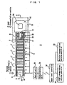
- FIG. 1 to 7 shows a transportation system 2 according to an embodiment.
- a reference numeral 4 denotes a conveyor.
- the conveyor 4 includes three kinds of units, i.e., a reticle side station 6, a conveyor unit 7, and a FOUP side unit 8. These units 6 to 8 are operated independently, and each of the units 6 to 8 functions as a buffer for storing reticle cassettes (articles) 18 one by one.
- a station 10 is connected to the FOUP side unit 8 of the conveyor 4.
- a reference numeral 12 denotes a groove formed in the station 10.
- a rail vehicle 14 travels along the groove 12.
- the rail vehicle 14 includes a cart 15 and a lifter 16.
- the rail vehicle 14 is guided along a travel rail 34 shown in FIG. 4 .
- the rail vehicle 14 may be equipped with a motor to travel by itself. Alternatively, the rail vehicle 14 may be towed by a chain or the like.
- the lifter 16 is elevated or lowered by an elevation arm 17. In the embodiment, the elevation arm 17 is provided at the center in the travel direction of the lifter 16. Alternatively, the elevation arm 17 may be provided near the conveyor 4 opposite to the station 10.
- the reticle cassette 18 is a cassette storing a reticle for exposure of semiconductors or liquid crystal display panels.
- the small cassette as the target of transportation is not limited to the reticle cassette, and may be a cassette as a target of spattering.
- a flange 20 is provided at an upper portion of the reticle cassette 18 for allowing an overhead traveling vehicle 42 shown in FIG. 4 to chuck the flange 20 for transportation of the reticle cassette 18.
- a reference numeral 22 denotes a dummy FOUP.
- the dummy FOUP 22 is placed on the station 10.
- An overhead traveling vehicle 52 shown in FIG. 4 chucks a flange 24 of the dummy FOUP 22 for transportation of the dummy FOUP 22.
- the outer shape of the dummy FOUP 22 is similar to that of a normal FOUP for transportation of semiconductor wafers.
- the respective conveyor units 6 to 8 and the rail vehicle 14 of the transportation system 2 are controlled by a control unit 26.
- the control unit 26 communicates with an upper level controller 30 through a communication unit 28.
- the upper level controller 30 communicates with a reticle transportation vehicle controller 32 as a controller in a first transportation system and a FOUP transportation vehicle controller 33 as a controller in a second transportation system.
- the control unit 26 communicates with the controllers 32, 33 through the communication unit 28 and the upper level controller 30.
- communication units for communication with the overhead traveling vehicles 42, 52 shown in FIG. 4 may be provided in the reticle side station 6 and the station 10 for allowing the overhead traveling vehicles 42, 52 to directly communicate with the stations 6, 10.
- FIG. 2 shows a control system of the transportation system 2.
- the rail vehicle 14 includes the cart 15 and the lifter 16.
- the conveyor 4 includes the FOUP side unit 8 and a plurality of the conveyor units 7, and the reticle side station 6.
- the units 7, 8, and the station 6 are operated independently to function as an accumulation conveyor.
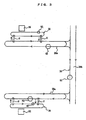
- FIG. 3 shows the usage environment of the transportation system 2 according to the embodiment.
- a reference numeral 38 denotes a FOUP transportation system.
- the FOUP transportation system 38 is an example of a second transportation system for transportation of large articles.
- the FOUP transportation system 38 uses the overhead traveling vehicle 52 shown in FIG. 4 , and includes a plurality of intra-bay routes 38a, and an inter-bay route 38b connecting the intra-bay routes 38a.
- the overhead traveling vehicle 52 travels in a direction indicated by an arrow in FIG. 3 .
- the reticle transportation system 36 is a system for transporting a reticle cassette storing a reticle between a reticle magazine 39 and an exposure apparatus (not shown) in one bay.
- the reticle transportation system 36 is an example of the first transportation system for transporting small articles in the claims.
- the reticle transportation system 36 uses the overhead traveling vehicle 42 shown in FIG. 4 .
- the overhead traveling vehicle 42 travels around the bay in a direction indicated by an arrow in FIG. 3 , and transports the reticle cassette between the different bays using the transportation system 2 and the FOUP transportation system 38.
- at least a pair of the transportation systems 2 according to the embodiment are provided between the transportation systems 36, 38, and the transportation systems 2 have different directions of transporting the reticle cassettes.
- reference numerals 40, 50 denote travel rails.
- the travel rails 40, 50 are supported by support columns 41,51, e.g., in a clean room of a building.
- the overhead traveling vehicle 42 for reticle transportation includes a travel cart 44, a power receiving cart 45 for receiving electricity from the travel rail 40, and a lateral feed unit 46 for laterally feeding a ⁇ drive 47 and portion below the ⁇ drive 47 relative to the travel rail 40.
- the ⁇ drive 47 rotates an elevation drive unit 48 in a horizontal plane and controls the orientation of the reticle cassette 18.
- the elevation drive unit 48 elevates/lowers the elevation frame 49 chucking the reticle cassette 18 for transferring the reticle cassette 18 to/from the exposure apparatus, the station of the reticle magazine, or the reticle side station 6.
- the lateral feed unit 46 and the ⁇ drive 47 may not be provided.
- a travel cart 54 travels inside the travel rail 50.
- a power receiving cart 55 receives electricity, and a lateral feed unit 56 laterally feeds a ⁇ drive 57, and portion below the ⁇ drive 57 relative to the travel rail 50.
- the ⁇ drive 57 rotates an elevation drive unit 58 and portion below the elevation unit 58 in a horizontal plane.
- An elevation frame 59 chucks the dummy FOUP or the normal FOUP storing a dummy FOUP 22 and a semiconductor cassette at the flange 24.
- the elevation frame 59 is elevated/lowered by the elevation drive unit 58. In this manner, the dummy FOUP 22 is transferred to/from the station 10.
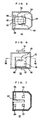
- FIGS. 5 to 7 show a shape of the dummy FOUP 22.
- the shape of the dummy FOUP 22 is similar to that of the FOUP for transportation of semiconductor wafers.
- the dummy FOUP 22 has an opening 60 on a side surface, and has a hole 62 at the bottom.
- the reticle cassettes 18 are placed on tables 64, e.g. provided at four positions in the dummy FOUP 22. Gaps between the tables 64 is larger than the width of the lifter.
- the elevation arm 17 is elevated to lift up the lifter 16, thereby lifting up the reticle cassette 18 on the conveyor or in the dummy FOUP 22.
- the elevation arm 17 passes through the hole 62, and the lifter and the reticle cassette 18 pass through the opening 60 to move the reticle cassette 18 toward the inside or outside of the dummy FOUP 22.
- the elevation arm 17 in FIG. 4 is positioned at the center in the traveling direction of the lifter 16. Therefore, the dummy FOUP 22 needs to have the hole 62. However, if the elevation arm 17 is provided on a side of the lifter 16 near the conveyor 4, the hole 62 is not required, or the length of the hole 62 can be reduced.
- the rail vehicle 14 is provided below the conveyor 4. Alternatively, the travel rail 34 and the rail vehicle 14 may be provided above the conveyor 4. In this case, the flange 20 is chucked and lifted up, and the reticle cassette 18 is laterally moved toward the inside or outside of the dummy FOUP 22.
- a SCARA arm or a slide fork may be used to transfer the reticle cassette 18.
- the SCARA arm or the slide fork is attached to a lifter (not shown), the flange 20 is chucked by the SCARA arm or the slide fork and the reticle cassette 18 is moved laterally.
- the opening 60 of the dummy FOUP 22 needs to be large so that the arm can pass through the opening 60.
- the position of transferring the reticle cassette 18 tends to be inaccurate in comparison with the case of using the rail vehicle 14 or the SCARA arm.
- the dummy FOUP 22 storing the reticle cassette is unloaded from the overhead traveling vehicle 52 to the station 10. Then, the rail vehicle 14 travels to the right side in FIG. 4 , the elevation arm 17 passes through the hole 62 of the bottom surface of the dummy FOUP 22, the lifter 16 passes through the opening 60, and the lifter 16 moves into the dummy FOUP 22. By lifting up the lifter 16, the reticle cassette 18 is transferred from the table 64 to the lifter 16. Thereafter, the rail vehicle 14 moves backwardly, and the lifter 16 is lowered.
- the reticle cassette 18 is transferred to the FOUP side unit 8 of the conveyor 4.
- the conveyor 4 includes a plurality of units 7.
- the units 7 are used as the buffers.
- the cassette 18 waits on the conveyor 4 until the cassette 18 is transferred to the overhead traveling vehicle 42 of the reticle transportation system 36.
- the units 7 of the conveyor 4 is used as the buffers so that the reticle cassette 18 can wait on the conveyor 4 until an empty dummy FOUP 22 arrives at the station 10.
- the lifter 16 is lifted up to pick up the reticle cassette 18.
- the rail vehicles 14 travels to the right side in FIG. 4 , and the lifter 16 is lowered to unload the reticle cassette 18 onto the table 64 of the dummy FOUP 22.
- the reticle cassette 18 is shown as an example of the small article, and the FOUP is shown as an example of the large article.
- the present invention is not limited in this respect.
- the types of the reticle transportation system 36 and the FOUP transportation system 38 can be selected arbitrarily. Instead of using the system of overhead traveling vehicles, a system of rail vehicles, a system of long-distance conveyors, or a system of stacker cranes may be used.
Landscapes
- Engineering & Computer Science (AREA)
- Mechanical Engineering (AREA)
- Container, Conveyance, Adherence, Positioning, Of Wafer (AREA)
Claims (4)
- System (2) zum Transport von kleinen Kassetten (18), die kleine Artikel enthalten, zwischen einem ersten Transportsystem (36) zum Transport der kleinen Kassetten und einem zweiten Transportsystem (38) zum Transport von großen Kassetten, die große Artikel enthalten, wobei das System Folgendes aufweist:eine kleine Kassette (18), die die kleinen Artikel lagern kann;eine Ersatzkassette (22), die die kleine Kassette (18) lagern kann, und die von dem zweiten Transportsystem (38) transportiert werden kann, wobei die Ersatzkassette (22) eine Öffnung (60) hat, um zu gestatten, dass die kleine Kassette (18) sich in die Ersatzkassette (22) hinein und aus dieser heraus bewegt;eine Fördereinrichtung (4) zum Transport der kleinen Kassetten (18) zwischen dem ersten Transportsystem (36) und dem zweiten Transportsystem (38);eine Station (10), die die Ersatzkassette (22) zu/von dem zweiten Transportsystem (38) übergeben kann; undTransfermittel (14) zur Übergabe der kleinen Kassette (18) zwischen der Ersatzkassette (22) in der Station (10) und der Fördereinrichtung (4), wobeidie Transfermittel (14) Hubmittel (16) aufweisen, um die kleine Kassette anzuheben, und Bewegungsmittel (15), um die angehobene kleine Kassette (18) zwischen der Ersatzkassette (22) an der Station (10) und der Fördereinrichtung (4) durch die Öffnung (60) zu bewegen.
- Transportsystem (2) nach Anspruch 1, wobei die Öffnung (60) auf einer Seitenfläche der Ersatzkassette (22) vorgesehen ist, und wobei die Transfermittel (14) einen Wagen aufweisen, der entlang einer Schiene (34) als die Bewegungsmittel (15) geführt ist, und einen Hubrahmen (49, 59) als die Hubmittel (16).
- Transportsystem (2) nach Anspruch 1, wobei die Fördereinrichtung (4) auch als ein Puffer für die kleine Kassette (18) verwendet wird.
- Transportverfahren zum Transportieren von kleinen Kassetten (18), die kleine Artikel enthalten, zwischen einem ersten Transportsystem (36) zum Transport von kleinen Kassetten (18) und einem zweiten Transportsystem (38) zum Transport von großen Kassetten, die große Artikel enthalten, wobei das Verfahren gekennzeichnet ist durchVorsehen einer Fördereinrichtung (4) zum Transportieren der kleinen Kassette (18) zwischen dem ersten Transportsystem (36) und dem zweiten Transportsystem (38);Vorsehen einer Station (10) zum Tragen einer Dummy- bzw. Ersatzkassette (22), die von dem zweiten Transportsystem (38) transportiert werden kann, zwischen dem zweiten Transportsystem (22) und der Fördereinrichtung (4); undVorsehen von Transfermitteln (14) zum Transport der kleinen Kassette (18) zwischen der Ersatzkassette (22) in der Station (10) und der Fördereinrichtung (4),
wobei die Ersatzkassette (22) die kleine Kassette (18) aufnehmen kann und eine Öffnung (60) hat, um zu gestatten, dass die kleine Kassette (18) sich in die Ersatzkassette (22) hinein und aus dieser heraus bewegt;
wobei die Transfermittel (14) Hubmitel (16) und Bewegungsmittel (15) aufweisen;
wobei die Fördereinrichtung (4) die kleine Kassette (18) zwischen dem ersten Transportsystem (36) und den Transfermitteln (14) transportiert;
wobei die Transfermittel (14) die kleine Kassette (18) anheben; und
wobei die angehobene kleine Kassette (18) zwischen der Ersatzkassette (22) an der Station (10) und der Fördereinrichtung (4) durch die Öffnung (60) durch die Bewegungsmittel (15) transportiert wird.
Applications Claiming Priority (1)
| Application Number | Priority Date | Filing Date | Title |
|---|---|---|---|
| JP2006112401A JP4200387B2 (ja) | 2006-04-14 | 2006-04-14 | 搬送システム |
Publications (2)
| Publication Number | Publication Date |
|---|---|
| EP1845552A1 EP1845552A1 (de) | 2007-10-17 |
| EP1845552B1 true EP1845552B1 (de) | 2009-03-11 |
Family
ID=38283907
Family Applications (1)
| Application Number | Title | Priority Date | Filing Date |
|---|---|---|---|
| EP07007643A Not-in-force EP1845552B1 (de) | 2006-04-14 | 2007-04-13 | Transportsystem und Transportverfahren |
Country Status (5)
| Country | Link |
|---|---|
| US (1) | US7806648B2 (de) |
| EP (1) | EP1845552B1 (de) |
| JP (1) | JP4200387B2 (de) |
| DE (1) | DE602007000656D1 (de) |
| TW (1) | TW200807490A (de) |
Cited By (1)
| Publication number | Priority date | Publication date | Assignee | Title |
|---|---|---|---|---|
| CN102514920A (zh) * | 2011-12-16 | 2012-06-27 | 乌毡帽酒业有限公司 | 一种定位结构 |
Families Citing this family (7)
| Publication number | Priority date | Publication date | Assignee | Title |
|---|---|---|---|---|
| US7591624B2 (en) * | 2006-01-09 | 2009-09-22 | International Business Machines Corporation | Reticle storage pod (RSP) transport system utilizing FOUP adapter plate |
| DE112008001754T5 (de) * | 2007-07-09 | 2010-05-20 | Middlesex General Industries, Inc., Woburn | System und Verfahren zur Verbesserung des Durchsatzes und der Vehikelauslastung von Einschienenbahnfabriktransportsystemen |
| US8977387B2 (en) * | 2009-10-29 | 2015-03-10 | Taiwan Semiconductor Manufacturing Company, Ltd. | System and method for overhead cross-system transportation |
| WO2015045583A1 (ja) | 2013-09-27 | 2015-04-02 | 村田機械株式会社 | 物品の支持装置及び支持装置への2種類の物品の載置方法 |
| WO2015045711A1 (ja) | 2013-09-30 | 2015-04-02 | 村田機械株式会社 | 保管庫 |
| JP6493339B2 (ja) * | 2016-08-26 | 2019-04-03 | 村田機械株式会社 | 搬送容器、及び収容物の移載方法 |
| CN114649250B (zh) * | 2022-05-20 | 2022-08-05 | 弥费实业(上海)有限公司 | 供存储库与oht交换晶圆盒的运输装置、天车窗口及存储库 |
Family Cites Families (12)
| Publication number | Priority date | Publication date | Assignee | Title |
|---|---|---|---|---|
| JPS6467932A (en) | 1987-09-08 | 1989-03-14 | Mitsubishi Electric Corp | Semiconductor wafer cassette conveyor |
| US5668056A (en) * | 1990-12-17 | 1997-09-16 | United Microelectronics Corporation | Single semiconductor wafer transfer method and manufacturing system |
| JPH0637227U (ja) | 1992-10-23 | 1994-05-17 | 村田機械株式会社 | 搬送システム |
| US5855465A (en) * | 1996-04-16 | 1999-01-05 | Gasonics International | Semiconductor wafer processing carousel |
| JP3682170B2 (ja) | 1998-09-09 | 2005-08-10 | 株式会社東芝 | カセット搬送システム、半導体露光装置、及びレチクル運搬方法 |
| US6568896B2 (en) * | 2001-03-21 | 2003-05-27 | Applied Materials, Inc. | Transfer chamber with side wall port |
| JP3734432B2 (ja) | 2001-06-07 | 2006-01-11 | 三星電子株式会社 | マスク搬送装置、マスク搬送システム及びマスク搬送方法 |
| JP4019675B2 (ja) | 2001-10-01 | 2007-12-12 | 神鋼電機株式会社 | 搬送装置 |
| JP2003188229A (ja) * | 2001-12-18 | 2003-07-04 | Hitachi Kasado Eng Co Ltd | ウエハ製造システムおよびウエハ製造方法 |
| JP4220173B2 (ja) | 2002-03-26 | 2009-02-04 | 株式会社日立ハイテクノロジーズ | 基板の搬送方法 |
| US6848882B2 (en) * | 2003-03-31 | 2005-02-01 | Taiwan Semiconductor Manufacturing Co., Ltd | Apparatus and method for positioning a cassette pod onto a loadport by an overhead hoist transport system |
| JP2005136294A (ja) | 2003-10-31 | 2005-05-26 | Murata Mach Ltd | 移載装置 |
-
2006
- 2006-04-14 JP JP2006112401A patent/JP4200387B2/ja not_active Expired - Fee Related
-
2007
- 2007-02-12 TW TW096105091A patent/TW200807490A/zh unknown
- 2007-04-09 US US11/783,323 patent/US7806648B2/en active Active
- 2007-04-13 DE DE602007000656T patent/DE602007000656D1/de active Active
- 2007-04-13 EP EP07007643A patent/EP1845552B1/de not_active Not-in-force
Cited By (2)
| Publication number | Priority date | Publication date | Assignee | Title |
|---|---|---|---|---|
| CN102514920A (zh) * | 2011-12-16 | 2012-06-27 | 乌毡帽酒业有限公司 | 一种定位结构 |
| CN102514920B (zh) * | 2011-12-16 | 2013-11-20 | 乌毡帽酒业有限公司 | 一种定位结构 |
Also Published As
| Publication number | Publication date |
|---|---|
| JP2007287877A (ja) | 2007-11-01 |
| DE602007000656D1 (de) | 2009-04-23 |
| TW200807490A (en) | 2008-02-01 |
| EP1845552A1 (de) | 2007-10-17 |
| US20070284217A1 (en) | 2007-12-13 |
| US7806648B2 (en) | 2010-10-05 |
| JP4200387B2 (ja) | 2008-12-24 |
Similar Documents
| Publication | Publication Date | Title |
|---|---|---|
| EP3476772B1 (de) | Fördersystem | |
| KR101363836B1 (ko) | 스토커 | |
| EP1845552B1 (de) | Transportsystem und Transportverfahren | |
| CN108698757B (zh) | 输送系统 | |
| JP5088468B2 (ja) | 懸垂式搬送台車を用いた搬送システム | |
| US20080240892A1 (en) | Storage buffer device for automated material handling systems | |
| KR20080072817A (ko) | 현수식 승강 반송 대차에 있어서의 물품의 수수 방법 및장치 | |
| KR101414530B1 (ko) | 반송차 시스템 | |
| WO2011083525A1 (ja) | 搬送車システム | |
| JP7323059B2 (ja) | 搬送車システム | |
| KR20210054992A (ko) | 기판 처리 장치 및 기판 수납 용기 보관 방법 | |
| JP6566051B2 (ja) | 保管装置及び搬送システム | |
| JP5145686B2 (ja) | 搬送システム | |
| JP2007096145A (ja) | 懸垂式昇降搬送台車における物品の授受方法並びに装置 | |
| JP2005136294A (ja) | 移載装置 | |
| JP2010241547A (ja) | 走行車システム | |
| JP7173291B2 (ja) | 搬送車システム | |
| JP2008019017A (ja) | 物品収納装置 | |
| JP2013165177A (ja) | ストッカー装置 | |
| JP6578794B2 (ja) | 搬送システム | |
| KR20240096121A (ko) | 물류 반송 설비 및 물류 반송 방법 | |
| CN116364615A (zh) | 层间传送装置及包括其的物流传送系统 | |
| JP2007005503A (ja) | 容器移載装置及び移載方法 | |
| JP2008162795A (ja) | 自動倉庫システム | |
| JP2005231868A (ja) | 物品搬送装置 |
Legal Events
| Date | Code | Title | Description |
|---|---|---|---|
| PUAI | Public reference made under article 153(3) epc to a published international application that has entered the european phase |
Free format text: ORIGINAL CODE: 0009012 |
|
| AK | Designated contracting states |
Kind code of ref document: A1 Designated state(s): AT BE BG CH CY CZ DE DK EE ES FI FR GB GR HU IE IS IT LI LT LU LV MC MT NL PL PT RO SE SI SK TR |
|
| AX | Request for extension of the european patent |
Extension state: AL BA HR MK YU |
|
| 17P | Request for examination filed |
Effective date: 20080314 |
|
| AKX | Designation fees paid |
Designated state(s): DE FR |
|
| GRAP | Despatch of communication of intention to grant a patent |
Free format text: ORIGINAL CODE: EPIDOSNIGR1 |
|
| GRAS | Grant fee paid |
Free format text: ORIGINAL CODE: EPIDOSNIGR3 |
|
| GRAA | (expected) grant |
Free format text: ORIGINAL CODE: 0009210 |
|
| AK | Designated contracting states |
Kind code of ref document: B1 Designated state(s): DE FR |
|
| REF | Corresponds to: |
Ref document number: 602007000656 Country of ref document: DE Date of ref document: 20090423 Kind code of ref document: P |
|
| PLBE | No opposition filed within time limit |
Free format text: ORIGINAL CODE: 0009261 |
|
| STAA | Information on the status of an ep patent application or granted ep patent |
Free format text: STATUS: NO OPPOSITION FILED WITHIN TIME LIMIT |
|
| 26N | No opposition filed |
Effective date: 20091214 |
|
| REG | Reference to a national code |
Ref country code: FR Ref legal event code: PLFP Year of fee payment: 9 |
|
| PGFP | Annual fee paid to national office [announced via postgrant information from national office to epo] |
Ref country code: FR Payment date: 20150421 Year of fee payment: 9 |
|
| REG | Reference to a national code |
Ref country code: FR Ref legal event code: ST Effective date: 20161230 |
|
| PG25 | Lapsed in a contracting state [announced via postgrant information from national office to epo] |
Ref country code: FR Free format text: LAPSE BECAUSE OF NON-PAYMENT OF DUE FEES Effective date: 20160502 |
|
| PGFP | Annual fee paid to national office [announced via postgrant information from national office to epo] |
Ref country code: DE Payment date: 20230420 Year of fee payment: 17 |
|
| REG | Reference to a national code |
Ref country code: DE Ref legal event code: R119 Ref document number: 602007000656 Country of ref document: DE |
|
| PG25 | Lapsed in a contracting state [announced via postgrant information from national office to epo] |
Ref country code: DE Free format text: LAPSE BECAUSE OF NON-PAYMENT OF DUE FEES Effective date: 20241105 |
|
| PG25 | Lapsed in a contracting state [announced via postgrant information from national office to epo] |
Ref country code: DE Free format text: LAPSE BECAUSE OF NON-PAYMENT OF DUE FEES Effective date: 20241105 |