EP1841683B1 - Vorrichtung zum öffnen einer mit einem kronenkorken verschlossenen flasche - Google Patents
Vorrichtung zum öffnen einer mit einem kronenkorken verschlossenen flasche Download PDFInfo
- Publication number
- EP1841683B1 EP1841683B1 EP05812837A EP05812837A EP1841683B1 EP 1841683 B1 EP1841683 B1 EP 1841683B1 EP 05812837 A EP05812837 A EP 05812837A EP 05812837 A EP05812837 A EP 05812837A EP 1841683 B1 EP1841683 B1 EP 1841683B1
- Authority
- EP
- European Patent Office
- Prior art keywords
- bottle
- neck
- supporting member
- crown cork
- pushing
- Prior art date
- Legal status (The legal status is an assumption and is not a legal conclusion. Google has not performed a legal analysis and makes no representation as to the accuracy of the status listed.)
- Expired - Lifetime
Links
Images
Classifications
-
- B—PERFORMING OPERATIONS; TRANSPORTING
- B67—OPENING, CLOSING OR CLEANING BOTTLES, JARS OR SIMILAR CONTAINERS; LIQUID HANDLING
- B67B—APPLYING CLOSURE MEMBERS TO BOTTLES JARS, OR SIMILAR CONTAINERS; OPENING CLOSED CONTAINERS
- B67B7/00—Hand- or power-operated devices for opening closed containers
- B67B7/16—Hand- or power-operated devices for opening closed containers for removing flanged caps, e.g. crown caps
- B67B7/162—Hand- or power-operated devices for opening closed containers for removing flanged caps, e.g. crown caps the removing device being formed by at least two articulated parts, e.g. pliers
Definitions
- the invention relates to a device for opening a bottle capped with a crown cork according to the preamble of patent claim 1.
- Various devices are known to open bottles that are closed with a crown cork.
- Known devices work with a lever which is supported on the one hand on the crown cork itself or on the bottle and on the other hand pushes the lower edge of the crown cork during the opening process upwards.
- the crown cork is lifted relatively slowly from the bottle and thereby deformed, so that only a slight hissing noise arises when opening.
- the deformed crown cork is also not suitable to close the bottle even makeshift again.
- the GB 111 954 A discloses a device for removing bottle caps, which can be placed on the bottle such that a bow enclosing the bottle neck prevents it from falling down after opening.
- the opening process itself corresponds to that of the solutions described above.
- a bottle opener described which has a retaining ring which can be placed on the neck of a bottle.
- a two-armed lever is pivotally mounted, which has an actuating surface at one end and a pressure transmitting member at its other end.
- the pressure transmitting member is clamped under the bottle cap and pushed by the operation of the lever upwards, whereby the bottle cap can be lifted.
- the speed with which the bottle is opened, and thus the opening noise depends primarily on the skill of the user.
- Object of the present invention is to avoid these disadvantages and to develop the device of the type described above so that even an untrained user always achieved a strong opening noise.
- Another object of the present invention is to design the device so that it is constructed as disposable items that can be produced at low cost. In addition, it should allow the device to open the bottle so that the crown cork is deformed or damaged as little as possible to allow at least provisional reclosure of the bottle after opening.
- the support member can be pushed with relatively little clearance on the bottle neck and ultimately rests on the flared part of the bottle.
- the pressure member is arcuate and initially moves away from the support member from the neck of the bottle to abut again at its end immediately below the crown cork with a pressure surface on the bottle neck.
- the pressure member is pushed towards the neck of the bottle, thereby exerting an upward force on the crown cork. Due to the special geometry of the device is achieved that this process is very fast, whereby a strong opening noise is achieved in each case.
- Another advantage of the device according to the invention is that due to the high speed of the force build-up, an extremely small deformation of the crown cork is achieved, so that it can be used to re-close the bottle.
- bottle opener according to the invention can be operated with one hand, in contrast to a variety of known solutions, since both the neck of the bottle and the opener includes and can be operated with one hand. It is thus the subject of the invention is a "one-hand bottle opener".
- a particularly simple structure which enables a very cost-effective production as a mass-produced article, is achieved in that the support member and the pressure member are integrally made of plastic.
- the support member and the pressure member are integrally made of plastic.
- the support member and the pressure member are made of different materials in the two-component injection molding.
- the use of the device can be particularly facilitated by the fact that the pressure member is biased with respect to the bottleneck when placed on the bottle neck support member. Through this design it is achieved that with appropriate placement a suitable opening for the bottle position is achieved in any case. This allows the use of the device even by inexperienced people even when poor lighting conditions are present and an optical monitoring of the opening process is not possible.
- An alternative embodiment provides that the pressure member is pivotally mounted on the support member. Such an embodiment makes it possible to put the device upside down on the neck of the bottle and thus to keep it ready for use.
- a further embodiment variant of the invention provides that a plurality of pressure members are integrally formed or fastened to the support member.
- the plurality of pressure members may be equidistantly spaced around the neck of the bottle to allow the crown cork to lift off exactly in the axial direction.
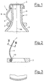
- Fig. 1 the device 1 according to the invention is placed on a bottle 2, which is closed with a crown cork 5.
- the device 1 consists of an annular support member 3, on which an arcuate pressure member 4 is integrally formed.
- the representation of Fig. 1 shows the device 1 immediately before use.
- the support member 3 is placed on the neck 6 of the bottle 2 and is based on the flared portion 9 of the bottle 2 from.
- a pressure surface 7 at the end of the pressure member 4 is located directly below the crown cork 5. By a pressure on the pressure member 4 in the direction of the arrow 8, this is brought into an extended position, whereby the pressure surface 7 is moved upward and the crown cork 5 lifts from the bottle 2.
- the geometry of the device 1 is formed so that the lifting of the crown cork 5 is effected by the penetration of the curved spring 4, the movement is very fast in the direction of the axis 6a of the neck 6 of the bottle 2, so that a powerful opening sound is achieved ,
- Fig. 2 The variant of Fig. 2 is different from that of Fig. 1 in that the support member 3 is formed as a plastic part, which has a joint 10, on which the pressure member 4 is articulated.
- the pressure member 4 is formed as a steel spring having a slight curvature in cross section, as is made Fig. 3 is apparent. In this way, a fast and powerful penetration of the spring is achieved.
- the present invention makes it possible to open bottles which are provided with a crown cork, so that a strong and rich opening sound is achieved largely independently of the operation.
Landscapes
- Engineering & Computer Science (AREA)
- Mechanical Engineering (AREA)
- Devices For Opening Bottles Or Cans (AREA)
- Closures For Containers (AREA)
Description
- Die Erfindung betrifft eine Vorrichtung zum Öffnen einer mit einem Kronenkorken verschlossenen Flasche gemäß dem Oberbegriff von Patentanspruch 1.
- Es sind verschiedene Vorrichtungen bekannt, um Flaschen zu öffnen, die mit einem Kronenkorken verschlossen sind. Bekannte Vorrichtungen arbeiten mit einem Hebel, der sich einerseits am Kronenkorken selbst oder an der Flasche abstützt und der andererseits während des Öffnungsvorganges den unteren Rand des Kronenkorks nach oben drückt. Bei üblicher Verwendung solcher Vorrichtung wird der Kronenkorken relativ langsam von der Flasche abgehoben und dabei verformt, so dass beim Öffnen lediglich ein leises Zischgeräusch entsteht. Der verformte Kronenkorken ist überdies nicht dazu geeignet, die Flasche auch nur behelfsmäßig wieder zu verschließen.
- Verschiedentlich besteht das Bedürfnis, auch beim Öffnen einer mit einem Kronenkork verschlossenen Flasche ein kräftiges Öffnungsgeräusch zu erzeugen, das etwa dem entspricht, das beim Öffnen einer Sektflasche entsteht. Aus der
WO 2004/067402 sind spezielle Kronenkorken bekannt, die das Entstehen eines solchen Geräusches begünstigen. Die Lautstärke und Intensität des Geräusches hängt aber nach wie vor davon ab, in welcher Weise der Öffnungsvorgang selbst durchgeführt wird. Bei Verwendung herkömmlicher Flaschenöffner und entsprechend ungünstiger Bedienung kann das Entstehen eines wunschgemäßen Öffnungsgeräusches nicht gewährleistet werden. Weitere Vorrichtungen zum Öffnen von Flaschen sind aus derUS 4,875,394 A , derUS 4,590,821 A und derUS 5,868,044 A bekannt. Auch mit solchen Vorrichtungen ist es ohne besondere Geschicklichkeit des Anwenders nicht möglich, Kronenkorken so zu öffnen, dass ein reproduzierbar kräftiges Öffnungsgeräusch erreicht wird. - Die
GB 111 954 A - Weiters zeigt die
US 6,062,107 A einen Öffner für Champagnerflaschen, der im Wesentlichen aus einer Gelenkhebelanordnung besteht. Dadurch wird die Öffnungskraft, die bei solchen Flaschen beträchtlich sein kann, verringert. Die Erzielung eines Öffnungsgeräuschs ist hierbei jedoch kein Thema, da sich dieses aufgrund des hohen Innendrucks unabhängig vom Öffnungsverfahrens jedenfalls ergibt. - Ferner ist in der
FR 727 478 A - Aufgabe der vorliegenden Erfindung ist es, diese Nachteile zu vermeiden und die Vorrichtung der oben beschriebenen Art so weiterzubilden, dass auch ein ungeübter Benützer stets ein kräftiges Öffnungsgeräusch erzielt. Eine weitere Aufgabe der vorliegenden Erfindung ist es, die Vorrichtung so auszubilden, dass sie als kostengünstig herstellbarer Einmalartikel aufgebaut ist. Darüber hinaus soll es die Vorrichtung ermöglichen, die Flasche so zu öffnen, dass der Kronenkork möglichst wenig verformt oder beschädigt wird, um ein zumindest behelfsmäßiges Wiederverschließen der Flasche nach dem Öffnen zu ermöglichen.
- Erfindungsgemäß werden diese Aufgaben durch die Merkmale von Patentanspruch 1 gelöst. Wesentlich an der Erfindung ist, dass das Stützglied mit relativ geringem Spiel auf den Flaschenhals aufgeschoben werden kann und letztlich auf dem sich konisch erweiternden Teil der Flasche aufsitzt. Das Druckglied ist bogenförmig ausgebildet und entfernt sich zunächst ausgehend vom Stützglied vom Hals der Flasche, um an seinem Ende wieder unmittelbar unterhalb des Kronenkorkens mit einer Druckfläche am Flaschenhals anzuliegen. Um die Flasche zu öffnen, wird nach dem Aufsetzen der Vorrichtung auf den Flaschenhals das Druckglied zum Flaschenhals hin gedrückt, wodurch eine nach oben wirkende Kraft auf den Kronenkork ausgeübt wird. Durch die spezielle Geometrie der Vorrichtung wird erreicht, dass dieser Vorgang sehr schnell erfolgt, wodurch ein kräftiges Öffnungsgeräusch in jedem Fall erzielt wird. Ein weiterer Vorteil der erfindungsgemäßen Vorrichtung besteht darin, dass durch die große Geschwindigkeit des Kraftaufbaus eine äußerst geringe Verformung des Kronenkorks erzielt wird, so dass diese zum erneuten Verschließen der Flasche verwendet werden kann.
- Ein weiterer wesentlicher Vorteil des erfindungsgemäßen Flaschenöffners besteht darin, dass er im Gegensatz zu einer Vielzahl bekannter Lösungen einhändig bedient werden kann, da mit einer Hand sowohl der Hals der Flasche als auch der Öffner umfasst und betätigt werden kann. Es handelt sich somit beim Gegenstand der Erfindung um einen "Einhandflaschenöffner".
- Ein besonders einfacher Aufbau, der eine sehr kostengünstige Herstellung als Massenartikel ermöglicht, wird dadurch erreicht, dass das Stützglied und das Druckglied einstückig aus Kunststoff hergestellt sind. Um einerseits eine entsprechend robuste und starre Ausführung des Stützgliedes zu ermöglichen und andererseits die erforderliche Elastizität des Druckgliedes zu gewährleisten, ist es besonders begünstigt, wenn das Stützglied und das Druckglied aus unterschiedlichen Materialien im Zweikomponenten-Spritzguss hergestellt sind.
- Die Verwendung der Vorrichtung kann dadurch besonders erleichtert werden, dass das Druckglied bei auf den Flaschenhals aufgesetztem Stützglied gegenüber dem Flaschenhals vorgespannt ist. Durch diese Ausführung wird erreicht, dass bei entsprechendem Aufsetzen eine zum Öffnen der Flasche geeignete Stellung in jedem Fall erreicht wird. Dies ermöglicht die Verwendung der Vorrichtung auch durch ungeübte Personen selbst dann, wenn schlechte Lichtverhältnisse vorliegen und eine optische Überwachung des Öffnungsvorganges nicht möglich ist. Eine alternative Ausführungsvariante sieht vor, dass das Druckglied gelenkig am Stützglied angebracht ist. Durch eine solche Ausführung ist es möglich, die Vorrichtung umgekehrt auf den Flaschenhals aufzusetzen und so zur Verwendung bereitzuhalten.
- Eine weitere Ausführungsvariante der Erfindung sieht vor, dass an dem Stützglied mehrere Druckglieder angeformt oder befestigt sind. Die mehreren Druckglieder können in gleichmäßigen Winkelabständen um den Flaschenhals angebracht sein, um ein Abheben des Kronenkorks genau in Axialrichtung zu ermöglichen.
- In der Folge wird die vorliegende Erfindung anhand dem in den Figuren dargestellten Ausführungsbeispiel näher erläutert. Es zeigen:
- Fig. 1
- eine auf eine Flasche aufgesetzte Vorrichtung in einer ersten Aus- führungsvariante der Erfindung im Schnitt;
- Fig. 2
- eine weitere Ausführungsvariante im Schnitt; und
- Fig. 3
- einen Schnitt nach Linie III-III in
Fig. 2 . - In der Darstellung von
Fig. 1 ist die erfindungsgemäße Vorrichtung 1 auf eine Flasche 2 aufgesetzt, die mit einem Kronenkorken 5 verschlossen ist. Die Vorrichtung 1 besteht aus einem ringförmigen Stützglied 3, an dem ein bogenförmiges Druckglied 4 einstückig angeformt ist. Die Darstellung vonFig. 1 zeigt die Vorrichtung 1 unmittelbar vor ihrer Verwendung. Das Stützglied 3 ist auf den Hals 6 der Flasche 2 aufgesetzt und stützt sich auf den sich konisch erweiternden Abschnitt 9 der Flasche 2 ab. Eine Druckfläche 7 am Ende des Druckgliedes 4 ist unmittelbar unterhalb des Kronenkorkens 5 gelegen. Durch einen Druck auf das Druckglied 4 in Richtung des Pfeils 8 wird dieses in eine gestreckte Position gebracht, wodurch die Druckfläche 7 nach oben bewegt wird und den Kronenkorken 5 von der Flasche 2 abhebt. Da die Geometrie der Vorrichtung 1 so ausgebildet ist, dass das Abheben des Kronenkorkens 5 durch das Durchschlagen der gekrümmten Feder 4 bewirkt wird, erfolgt die Bewegung sehr schnell in Richtung der Achse 6a des Halses 6 der Flasche 2, so dass ein kräftiges Öffnungsgeräusch erzielt wird. - Die Ausführungsvariante von
Fig. 2 unterscheidet sich von der vonFig. 1 dadurch, dass das Stützglied 3 als Kunststoffteil ausgebildet ist, das ein Gelenk 10 aufweist, an dem das Druckglied 4 gelenkig gelagert ist. Das Druckglied 4 ist dabei als Stahlfeder ausgebildet, die im Querschnitt eine leichte Krümmung aufweist, wie dies ausFig. 3 ersichtlich ist. Auf diese Weise wird ein schnelles und kräftiges Durchschlagen der Feder erreicht. - Die vorliegende Erfindung ermöglicht es, Flaschen die mit einem Kronenkork versehen sind, so zu öffnen, dass weitgehend unabhängig von der Bedienung ein kräftiges und sattes Öffnungsgeräusch erzielt wird.
Claims (7)
- Vorrichtung zum Öffnen einer mit einem Kronenkorken (5) verschlossenen Flasche (2), mit einem Stützglied (3) zur Abstützung der Vorrichtung (1), das im Wesentlichen ringförmig ausgebildet ist und einen Innendurchmesser aufweist, der ein Aufsetzen des Stützglieds (3) auf den Hals (6) der Flasche (2) ermöglicht, und mit einem Druckglied (4) zum Abheben des Kronenkorks (5), wobei das Druckglied (4) als mindestens eine bogenförmige Feder ausgebildet ist, die am Stützglied (3) angeformt oder befestigt ist und wobei das Druckglied (4) an seinem Ende eine Druckfläche (7) aufweist, die zum Abheben des Kronenkorks (5) bestimmt ist, dadurch gekennzeichnet, dass das Druckglied (4) durch das Durchschlagen der gekrümmten Feder in eine gestreckte Position gebracht wird.
- Vorrichtung nach Anspruch 1, dadurch gekennzeichnet, dass das Stützglied (3) und das Druckglied (4) einstückig aus Kunststoff hergestellt sind.
- Vorrichtung nach Anspruch 2, dadurch gekennzeichnet, dass das Stützglied (3) und das Druckglied (4) aus unterschiedlichen Materialien im Zweikomponenten-Spritzguss hergestellt sind.
- Vorrichtung nach einem der Ansprüche 1 bis 3, dadurch gekennzeichnet, dass das Druckglied (4) bei auf den Hals (6) der Flasche (2) aufgesetztem Stützglied (3) gegenüber dem Hals (6) der Flasche (2) vorgespannt ist.
- Vorrichtung nach einem der Ansprüche 1 bis 3, dadurch gekennzeichnet, dass das Druckglied (4) gelenkig am Stützglied (3) angebracht ist.
- Vorrichtung nach einem der Ansprüche 1 bis 5, dadurch gekennzeichnet, dass an dem Stützglied (3) mehrere Druckglieder (4) angeformt oder befestigt sind.
- Vorrichtung nach einem der Ansprüche 1 bis 6, dadurch gekennzeichnet, dass das Druckglied (4) in dem auf die Flasche (2) aufgesetzten Zustand annähernd kreisförmig gebogen ist, dass die größte Entfernung vom Hals (6) der Flasche (2) etwa dem Durchmesser des Halses (6) der Flasche (2) entspricht und dass eine Druckfläche (7) am Ende des Druckglieds (4) unmittelbar unterhalb des Kronenkorkens (5) am Hals (6) der Flasche (2) anliegt.
Priority Applications (1)
| Application Number | Priority Date | Filing Date | Title |
|---|---|---|---|
| SI200530845T SI1841683T1 (sl) | 2004-12-06 | 2005-12-06 | Naprava za odpiranje steklenice, zaprte s kronskim zamaškom |
Applications Claiming Priority (2)
| Application Number | Priority Date | Filing Date | Title |
|---|---|---|---|
| AT0204804A AT501099B8 (de) | 2004-12-06 | 2004-12-06 | Vorrichtung zum öffnen einer mit einem kronenkorken verschlossenen flasche |
| PCT/AT2005/000491 WO2006060834A1 (de) | 2004-12-06 | 2005-12-06 | Vorrichtung zum öffnen einer mit einem kronenkorken verschlossenen flasche |
Publications (2)
| Publication Number | Publication Date |
|---|---|
| EP1841683A1 EP1841683A1 (de) | 2007-10-10 |
| EP1841683B1 true EP1841683B1 (de) | 2009-08-19 |
Family
ID=35841927
Family Applications (1)
| Application Number | Title | Priority Date | Filing Date |
|---|---|---|---|
| EP05812837A Expired - Lifetime EP1841683B1 (de) | 2004-12-06 | 2005-12-06 | Vorrichtung zum öffnen einer mit einem kronenkorken verschlossenen flasche |
Country Status (6)
| Country | Link |
|---|---|
| EP (1) | EP1841683B1 (de) |
| AT (2) | AT501099B8 (de) |
| DE (1) | DE502005007965D1 (de) |
| ES (1) | ES2330870T3 (de) |
| SI (1) | SI1841683T1 (de) |
| WO (1) | WO2006060834A1 (de) |
Family Cites Families (10)
| Publication number | Priority date | Publication date | Assignee | Title |
|---|---|---|---|---|
| GB111954A (en) * | 1917-02-24 | 1917-12-20 | Theodore Henry Low | Improved Means for Removing Caps from Bottles. |
| FR727478A (fr) * | 1932-10-27 | 1932-06-18 | Dispositif pour l'ouverture de bouteilles ou autres récipients avec fermeture étanche, particulièrement ceux à bouchon-couronne ou à capsule | |
| US2551511A (en) * | 1947-10-16 | 1951-05-01 | Arthur Talbot | Pivoted lever bottle cap remover |
| US4590821A (en) * | 1984-11-09 | 1986-05-27 | Olson James C | Bottle cap remover |
| US4875394A (en) * | 1985-10-11 | 1989-10-24 | Crudgington Jr Cleveland B | Champagne bottle opener |
| AT393667B (de) * | 1988-07-05 | 1991-11-25 | Ratzinger Markus | Kronenkappenoeffner |
| US5868044A (en) * | 1996-04-25 | 1999-02-09 | Sonderman; Harry P. | Bottle stopper remover |
| US6062107A (en) * | 1999-01-19 | 2000-05-16 | Cover Co. Inc. | Beverage bottle cork or cap remover |
| NL1014242C1 (nl) * | 2000-02-01 | 2001-08-02 | Oscar Johannes Bruggeman | Flesopener. |
| WO2004067402A1 (de) * | 2003-01-30 | 2004-08-12 | Ottakringer Brauerei Ag | Flaschenverschluss |
-
2004
- 2004-12-06 AT AT0204804A patent/AT501099B8/de not_active IP Right Cessation
-
2005
- 2005-12-06 ES ES05812837T patent/ES2330870T3/es not_active Expired - Lifetime
- 2005-12-06 WO PCT/AT2005/000491 patent/WO2006060834A1/de not_active Ceased
- 2005-12-06 DE DE502005007965T patent/DE502005007965D1/de not_active Expired - Lifetime
- 2005-12-06 SI SI200530845T patent/SI1841683T1/sl unknown
- 2005-12-06 EP EP05812837A patent/EP1841683B1/de not_active Expired - Lifetime
- 2005-12-06 AT AT05812837T patent/ATE440068T1/de active
Also Published As
| Publication number | Publication date |
|---|---|
| EP1841683A1 (de) | 2007-10-10 |
| AT501099B8 (de) | 2007-02-15 |
| ES2330870T3 (es) | 2009-12-16 |
| AT501099B1 (de) | 2006-09-15 |
| ATE440068T1 (de) | 2009-09-15 |
| SI1841683T1 (sl) | 2010-01-29 |
| WO2006060834A1 (de) | 2006-06-15 |
| DE502005007965D1 (de) | 2009-10-01 |
| AT501099A1 (de) | 2006-06-15 |
Similar Documents
| Publication | Publication Date | Title |
|---|---|---|
| DE69311372T2 (de) | Zusatzeinrichtung zum verschliessen von dosen für getränke o.dgl. | |
| EP3224165A1 (de) | Vorrichtung zum transportieren von behältern | |
| DE4390860C2 (de) | Werkzeug zur Auflösung eines Unterdrucks in einem mit einem Schraubdeckel verschlossenen Konservenglas | |
| DE10322374A1 (de) | Verschluss | |
| DE19645565C1 (de) | Gerät zum Öffnen von Flaschen mit Naturkorken, vorzugsweise von Sektflaschen | |
| DE1548101A1 (de) | Verfahren zum Abziehen eines Uhrglases,Werkzeug zur Durchfuehrung dieses Verfahrens sowie Uhrglas zur Durchfuehrung des Verfahrens und Anwendung der Vorrichtung | |
| EP1847467B1 (de) | Stopfen für einen Behälter | |
| AT501099B1 (de) | Vorrichtung zum öffnen einer mit einem kronenkorken verschlossenen flasche | |
| EP1849711B1 (de) | Verschluss für eine Flasche | |
| DE2544903C2 (de) | Sekundärverschlußkappe | |
| EP0612684B1 (de) | Flaschenöffner für Kronenkorken | |
| DE8913678U1 (de) | Schneidgerät | |
| DE3922845C2 (de) | Verfahren und Vorrichtung zum Ent- und Wiederverkorken von Flaschen mit dem gezogenen Korken | |
| DE102008029783B3 (de) | Flaschenverschluss | |
| DE2940218C2 (de) | Vorrichtung zum Verschließen von Flaschen mit Kronenkorken o.dgl. | |
| DE9213716U1 (de) | Vorrichtung zum manuellen Verschließen von Flaschenkapseln | |
| EP2080733A1 (de) | Vorrichtung und Verfahren zum Öffnen von Champagnerflaschen | |
| DE102007029645A1 (de) | Flaschenverschluss mit Abdichthülse | |
| DE179269C (de) | ||
| DE4244574A1 (de) | ||
| EP1798192B1 (de) | Hilfsgerät zum öffnen von Drehverschlüssen | |
| DE4229077C2 (de) | Gerät zum Öffnen und Wiederverschließen von Kronkorkenverschlüssen | |
| DE1103786B (de) | Verschlussstopfen fuer Sektflaschen od. dgl. | |
| DE7007516U (de) | Vorrichtung zum oeffnen von flaschenverschlusskappen, insbesondere von schraubkappenverschluessen. | |
| DE20220476U1 (de) | Korkenzieher für Korken von Champagner-, Sekt-, Prosecco-, Cidre-Flaschen o.dgl. |
Legal Events
| Date | Code | Title | Description |
|---|---|---|---|
| PUAI | Public reference made under article 153(3) epc to a published international application that has entered the european phase |
Free format text: ORIGINAL CODE: 0009012 |
|
| 17P | Request for examination filed |
Effective date: 20070529 |
|
| AK | Designated contracting states |
Kind code of ref document: A1 Designated state(s): AT BE BG CH CY CZ DE DK EE ES FI FR GB GR HU IE IS IT LI LT LU LV MC NL PL PT RO SE SI SK TR |
|
| DAX | Request for extension of the european patent (deleted) | ||
| GRAP | Despatch of communication of intention to grant a patent |
Free format text: ORIGINAL CODE: EPIDOSNIGR1 |
|
| GRAS | Grant fee paid |
Free format text: ORIGINAL CODE: EPIDOSNIGR3 |
|
| GRAA | (expected) grant |
Free format text: ORIGINAL CODE: 0009210 |
|
| AK | Designated contracting states |
Kind code of ref document: B1 Designated state(s): AT BE BG CH CY CZ DE DK EE ES FI FR GB GR HU IE IS IT LI LT LU LV MC NL PL PT RO SE SI SK TR |
|
| REG | Reference to a national code |
Ref country code: GB Ref legal event code: FG4D Free format text: NOT ENGLISH |
|
| REG | Reference to a national code |
Ref country code: CH Ref legal event code: EP |
|
| REG | Reference to a national code |
Ref country code: IE Ref legal event code: FG4D |
|
| REF | Corresponds to: |
Ref document number: 502005007965 Country of ref document: DE Date of ref document: 20091001 Kind code of ref document: P |
|
| REG | Reference to a national code |
Ref country code: CH Ref legal event code: NV Representative=s name: ISLER & PEDRAZZINI AG |
|
| REG | Reference to a national code |
Ref country code: ES Ref legal event code: FG2A Ref document number: 2330870 Country of ref document: ES Kind code of ref document: T3 |
|
| LTIE | Lt: invalidation of european patent or patent extension |
Effective date: 20090819 |
|
| PG25 | Lapsed in a contracting state [announced via postgrant information from national office to epo] |
Ref country code: SE Free format text: LAPSE BECAUSE OF FAILURE TO SUBMIT A TRANSLATION OF THE DESCRIPTION OR TO PAY THE FEE WITHIN THE PRESCRIBED TIME-LIMIT Effective date: 20090819 Ref country code: LT Free format text: LAPSE BECAUSE OF FAILURE TO SUBMIT A TRANSLATION OF THE DESCRIPTION OR TO PAY THE FEE WITHIN THE PRESCRIBED TIME-LIMIT Effective date: 20090819 Ref country code: IS Free format text: LAPSE BECAUSE OF FAILURE TO SUBMIT A TRANSLATION OF THE DESCRIPTION OR TO PAY THE FEE WITHIN THE PRESCRIBED TIME-LIMIT Effective date: 20091219 Ref country code: FI Free format text: LAPSE BECAUSE OF FAILURE TO SUBMIT A TRANSLATION OF THE DESCRIPTION OR TO PAY THE FEE WITHIN THE PRESCRIBED TIME-LIMIT Effective date: 20090819 |
|
| REG | Reference to a national code |
Ref country code: SK Ref legal event code: T3 Ref document number: E 6323 Country of ref document: SK |
|
| PG25 | Lapsed in a contracting state [announced via postgrant information from national office to epo] |
Ref country code: LV Free format text: LAPSE BECAUSE OF FAILURE TO SUBMIT A TRANSLATION OF THE DESCRIPTION OR TO PAY THE FEE WITHIN THE PRESCRIBED TIME-LIMIT Effective date: 20090819 Ref country code: PL Free format text: LAPSE BECAUSE OF FAILURE TO SUBMIT A TRANSLATION OF THE DESCRIPTION OR TO PAY THE FEE WITHIN THE PRESCRIBED TIME-LIMIT Effective date: 20090819 |
|
| REG | Reference to a national code |
Ref country code: IE Ref legal event code: FD4D |
|
| PG25 | Lapsed in a contracting state [announced via postgrant information from national office to epo] |
Ref country code: PT Free format text: LAPSE BECAUSE OF FAILURE TO SUBMIT A TRANSLATION OF THE DESCRIPTION OR TO PAY THE FEE WITHIN THE PRESCRIBED TIME-LIMIT Effective date: 20091221 Ref country code: CY Free format text: LAPSE BECAUSE OF FAILURE TO SUBMIT A TRANSLATION OF THE DESCRIPTION OR TO PAY THE FEE WITHIN THE PRESCRIBED TIME-LIMIT Effective date: 20090819 Ref country code: BG Free format text: LAPSE BECAUSE OF FAILURE TO SUBMIT A TRANSLATION OF THE DESCRIPTION OR TO PAY THE FEE WITHIN THE PRESCRIBED TIME-LIMIT Effective date: 20091119 |
|
| PG25 | Lapsed in a contracting state [announced via postgrant information from national office to epo] |
Ref country code: RO Free format text: LAPSE BECAUSE OF FAILURE TO SUBMIT A TRANSLATION OF THE DESCRIPTION OR TO PAY THE FEE WITHIN THE PRESCRIBED TIME-LIMIT Effective date: 20090819 Ref country code: IE Free format text: LAPSE BECAUSE OF FAILURE TO SUBMIT A TRANSLATION OF THE DESCRIPTION OR TO PAY THE FEE WITHIN THE PRESCRIBED TIME-LIMIT Effective date: 20090819 Ref country code: DK Free format text: LAPSE BECAUSE OF FAILURE TO SUBMIT A TRANSLATION OF THE DESCRIPTION OR TO PAY THE FEE WITHIN THE PRESCRIBED TIME-LIMIT Effective date: 20090819 Ref country code: EE Free format text: LAPSE BECAUSE OF FAILURE TO SUBMIT A TRANSLATION OF THE DESCRIPTION OR TO PAY THE FEE WITHIN THE PRESCRIBED TIME-LIMIT Effective date: 20090819 |
|
| PLBE | No opposition filed within time limit |
Free format text: ORIGINAL CODE: 0009261 |
|
| STAA | Information on the status of an ep patent application or granted ep patent |
Free format text: STATUS: NO OPPOSITION FILED WITHIN TIME LIMIT |
|
| BERE | Be: lapsed |
Owner name: OTTAKRINGER BRAUEREI AG Effective date: 20091231 |
|
| 26N | No opposition filed |
Effective date: 20100520 |
|
| REG | Reference to a national code |
Ref country code: HU Ref legal event code: AG4A Ref document number: E007605 Country of ref document: HU |
|
| PG25 | Lapsed in a contracting state [announced via postgrant information from national office to epo] |
Ref country code: MC Free format text: LAPSE BECAUSE OF NON-PAYMENT OF DUE FEES Effective date: 20100701 |
|
| PG25 | Lapsed in a contracting state [announced via postgrant information from national office to epo] |
Ref country code: BE Free format text: LAPSE BECAUSE OF NON-PAYMENT OF DUE FEES Effective date: 20091231 Ref country code: GR Free format text: LAPSE BECAUSE OF FAILURE TO SUBMIT A TRANSLATION OF THE DESCRIPTION OR TO PAY THE FEE WITHIN THE PRESCRIBED TIME-LIMIT Effective date: 20091120 |
|
| PG25 | Lapsed in a contracting state [announced via postgrant information from national office to epo] |
Ref country code: LU Free format text: LAPSE BECAUSE OF NON-PAYMENT OF DUE FEES Effective date: 20091206 |
|
| PG25 | Lapsed in a contracting state [announced via postgrant information from national office to epo] |
Ref country code: TR Free format text: LAPSE BECAUSE OF FAILURE TO SUBMIT A TRANSLATION OF THE DESCRIPTION OR TO PAY THE FEE WITHIN THE PRESCRIBED TIME-LIMIT Effective date: 20090819 |
|
| REG | Reference to a national code |
Ref country code: FR Ref legal event code: PLFP Year of fee payment: 11 |
|
| REG | Reference to a national code |
Ref country code: FR Ref legal event code: PLFP Year of fee payment: 12 |
|
| REG | Reference to a national code |
Ref country code: FR Ref legal event code: PLFP Year of fee payment: 13 |
|
| PGFP | Annual fee paid to national office [announced via postgrant information from national office to epo] |
Ref country code: NL Payment date: 20171221 Year of fee payment: 13 Ref country code: FR Payment date: 20171226 Year of fee payment: 13 Ref country code: SK Payment date: 20171211 Year of fee payment: 13 |
|
| PGFP | Annual fee paid to national office [announced via postgrant information from national office to epo] |
Ref country code: CH Payment date: 20171221 Year of fee payment: 13 Ref country code: AT Payment date: 20171222 Year of fee payment: 13 Ref country code: SI Payment date: 20171207 Year of fee payment: 13 Ref country code: GB Payment date: 20171228 Year of fee payment: 13 |
|
| PGFP | Annual fee paid to national office [announced via postgrant information from national office to epo] |
Ref country code: ES Payment date: 20180124 Year of fee payment: 13 Ref country code: CZ Payment date: 20180116 Year of fee payment: 13 Ref country code: DE Payment date: 20180228 Year of fee payment: 13 |
|
| PGFP | Annual fee paid to national office [announced via postgrant information from national office to epo] |
Ref country code: HU Payment date: 20180209 Year of fee payment: 13 Ref country code: IT Payment date: 20171222 Year of fee payment: 13 |
|
| REG | Reference to a national code |
Ref country code: DE Ref legal event code: R119 Ref document number: 502005007965 Country of ref document: DE |
|
| PG25 | Lapsed in a contracting state [announced via postgrant information from national office to epo] |
Ref country code: CZ Free format text: LAPSE BECAUSE OF NON-PAYMENT OF DUE FEES Effective date: 20181206 |
|
| REG | Reference to a national code |
Ref country code: CH Ref legal event code: PL |
|
| REG | Reference to a national code |
Ref country code: NL Ref legal event code: MM Effective date: 20190101 |
|
| REG | Reference to a national code |
Ref country code: AT Ref legal event code: MM01 Ref document number: 440068 Country of ref document: AT Kind code of ref document: T Effective date: 20181206 |
|
| GBPC | Gb: european patent ceased through non-payment of renewal fee |
Effective date: 20181206 |
|
| REG | Reference to a national code |
Ref country code: SK Ref legal event code: MM4A Ref document number: E 6323 Country of ref document: SK Effective date: 20181206 |
|
| PG25 | Lapsed in a contracting state [announced via postgrant information from national office to epo] |
Ref country code: NL Free format text: LAPSE BECAUSE OF NON-PAYMENT OF DUE FEES Effective date: 20190101 |
|
| REG | Reference to a national code |
Ref country code: SI Ref legal event code: KO00 Effective date: 20190805 |
|
| PG25 | Lapsed in a contracting state [announced via postgrant information from national office to epo] |
Ref country code: DE Free format text: LAPSE BECAUSE OF NON-PAYMENT OF DUE FEES Effective date: 20190702 Ref country code: FR Free format text: LAPSE BECAUSE OF NON-PAYMENT OF DUE FEES Effective date: 20181231 Ref country code: SK Free format text: LAPSE BECAUSE OF NON-PAYMENT OF DUE FEES Effective date: 20181206 Ref country code: IT Free format text: LAPSE BECAUSE OF NON-PAYMENT OF DUE FEES Effective date: 20181206 Ref country code: SI Free format text: LAPSE BECAUSE OF NON-PAYMENT OF DUE FEES Effective date: 20181207 |
|
| PG25 | Lapsed in a contracting state [announced via postgrant information from national office to epo] |
Ref country code: HU Free format text: LAPSE BECAUSE OF NON-PAYMENT OF DUE FEES Effective date: 20181207 |
|
| PG25 | Lapsed in a contracting state [announced via postgrant information from national office to epo] |
Ref country code: CH Free format text: LAPSE BECAUSE OF NON-PAYMENT OF DUE FEES Effective date: 20181231 Ref country code: LI Free format text: LAPSE BECAUSE OF NON-PAYMENT OF DUE FEES Effective date: 20181231 Ref country code: AT Free format text: LAPSE BECAUSE OF NON-PAYMENT OF DUE FEES Effective date: 20181206 Ref country code: GB Free format text: LAPSE BECAUSE OF NON-PAYMENT OF DUE FEES Effective date: 20181206 |
|
| REG | Reference to a national code |
Ref country code: ES Ref legal event code: FD2A Effective date: 20200131 |
|
| PG25 | Lapsed in a contracting state [announced via postgrant information from national office to epo] |
Ref country code: ES Free format text: LAPSE BECAUSE OF NON-PAYMENT OF DUE FEES Effective date: 20181207 |