EP1840478B1 - Fensterbereich - Google Patents
Fensterbereich Download PDFInfo
- Publication number
- EP1840478B1 EP1840478B1 EP06405132.9A EP06405132A EP1840478B1 EP 1840478 B1 EP1840478 B1 EP 1840478B1 EP 06405132 A EP06405132 A EP 06405132A EP 1840478 B1 EP1840478 B1 EP 1840478B1
- Authority
- EP
- European Patent Office
- Prior art keywords
- opening
- window
- incoming air
- area according
- exit
- Prior art date
- Legal status (The legal status is an assumption and is not a legal conclusion. Google has not performed a legal analysis and makes no representation as to the accuracy of the status listed.)
- Expired - Lifetime
Links
Images


Classifications
-
- E—FIXED CONSTRUCTIONS
- E06—DOORS, WINDOWS, SHUTTERS, OR ROLLER BLINDS IN GENERAL; LADDERS
- E06B—FIXED OR MOVABLE CLOSURES FOR OPENINGS IN BUILDINGS, VEHICLES, FENCES OR LIKE ENCLOSURES IN GENERAL, e.g. DOORS, WINDOWS, BLINDS, GATES
- E06B7/00—Special arrangements or measures in connection with doors or windows
- E06B7/02—Special arrangements or measures in connection with doors or windows for providing ventilation, e.g. through double windows; Arrangement of ventilation roses
-
- F—MECHANICAL ENGINEERING; LIGHTING; HEATING; WEAPONS; BLASTING
- F24—HEATING; RANGES; VENTILATING
- F24F—AIR-CONDITIONING; AIR-HUMIDIFICATION; VENTILATION; USE OF AIR CURRENTS FOR SCREENING
- F24F12/00—Use of energy recovery systems in air conditioning, ventilation or screening
- F24F12/001—Use of energy recovery systems in air conditioning, ventilation or screening with heat-exchange between supplied and exhausted air
- F24F12/006—Use of energy recovery systems in air conditioning, ventilation or screening with heat-exchange between supplied and exhausted air using an air-to-air heat exchanger
-
- F—MECHANICAL ENGINEERING; LIGHTING; HEATING; WEAPONS; BLASTING
- F24—HEATING; RANGES; VENTILATING
- F24F—AIR-CONDITIONING; AIR-HUMIDIFICATION; VENTILATION; USE OF AIR CURRENTS FOR SCREENING
- F24F13/00—Details common to, or for air-conditioning, air-humidification, ventilation or use of air currents for screening
- F24F13/08—Air-flow control members, e.g. louvres, grilles, flaps or guide plates
- F24F13/18—Air-flow control members, e.g. louvres, grilles, flaps or guide plates specially adapted for insertion in flat panels, e.g. in door or window-pane
-
- F—MECHANICAL ENGINEERING; LIGHTING; HEATING; WEAPONS; BLASTING
- F24—HEATING; RANGES; VENTILATING
- F24F—AIR-CONDITIONING; AIR-HUMIDIFICATION; VENTILATION; USE OF AIR CURRENTS FOR SCREENING
- F24F7/00—Ventilation
- F24F7/007—Ventilation with forced flow
- F24F7/013—Ventilation with forced flow using wall or window fans, displacing air through the wall or window
-
- Y—GENERAL TAGGING OF NEW TECHNOLOGICAL DEVELOPMENTS; GENERAL TAGGING OF CROSS-SECTIONAL TECHNOLOGIES SPANNING OVER SEVERAL SECTIONS OF THE IPC; TECHNICAL SUBJECTS COVERED BY FORMER USPC CROSS-REFERENCE ART COLLECTIONS [XRACs] AND DIGESTS
- Y02—TECHNOLOGIES OR APPLICATIONS FOR MITIGATION OR ADAPTATION AGAINST CLIMATE CHANGE
- Y02B—CLIMATE CHANGE MITIGATION TECHNOLOGIES RELATED TO BUILDINGS, e.g. HOUSING, HOUSE APPLIANCES OR RELATED END-USER APPLICATIONS
- Y02B30/00—Energy efficient heating, ventilation or air conditioning [HVAC]
- Y02B30/56—Heat recovery units
Definitions
- the invention relates to a window area according to the preamble of claim 1, as they occur in exterior walls of buildings of all kinds, especially residential and office buildings.
- An arrangement according to the preamble of claim 1 is from the printing drift DE 20 2004 004 432 U1 known.
- the invention is based on the object to open up the possibility that in the window area a device is arranged for air exchange, the exhaust air from a closed room dissipates and supply air from the outside, in particular a fan, in which preferably between supply air and exhaust air in order to approximate the Temperature of the former is exchanged to the room temperature heat.
- the window area comprises ( Fig. 1-3 ) an external insulation 1, which preferably consists of a solid heat-insulating material such as Stypropor or mineral wool and forms a substantially continuous, a facade covering vertical layer of constant thickness, usually on the outside of a wall 2, which may be bricked or concreted example , Is arranged and outside of a small distance upstream rear ventilated outer lining 3, which consists for example of wood, natural stone or aluminum, is covered.
- a rectangular window opening 4 is recessed, in which a window frame 5 is arranged, which frames the window opening 4 on the inside.
- the outer insulation 1 In the region of a surrounding the window opening 4 soffit 6, the outer insulation 1 is also covered by the outer lining 3, in which there is a shutter 7 is guided.
- two window sash 8 are posted, which can be pivoted inwards.
- a narrow, also rectangular panel 9 is attached, which covers the inside of the outer insulation 1 between the window frame 5 and the slightly further than the outer insulation 1 cut wall 2.
- the cover 9 comprises a plate 10 and a same z.T. surrounding, z.T. covering, slightly projecting frame 11, which may partially coincide with a side part of the window frame 5 and a flat rectangular recess 12 surrounds, the bottom of which is formed by the plate 10.
- the window frame 5 and the panel 9 may be made of wood.
- an inlet air opening 13 is arranged in the plate 10, followed by a supply air line 14, which is bent horizontally and 90 ° through the outer insulation 1 to a slit-shaped outer air inlet opening 15 in the outer panel 3 at the Reveal 6 leads.
- a corresponding inner exhaust port 16 is disposed in the plate 10, of which an exhaust duct 17 horizontally and straight through the outer insulation 1 to an outer exhaust port 18 at the Outside leads. The exhaust duct 17 thus opens into the gap between the outer insulation 1 and the outer panel.
- a fan 19 is accurately used with a cuboid housing of approximately square ground plan, the height of which corresponds approximately or approximately to the sash 8. He has at its lying in the recess 12 rear side of a Zu Kunststoffeinlass which coincides with the inner supply air opening 13 and an exhaust outlet, which is connected to the inner exhaust port 16th covers. At the front, it has a supply air outlet 21 behind a grille 20, which lies approximately at the level of the exhaust air outlet and above, ie vertically offset, an exhaust air inlet 22 approximately at the level of the air inlet.
- the exhaust air inlet 22 of the fan 19 is connected to the exhaust air outlet through an exhaust air duct which forms a heat exchanger with a supply air duct connecting the air intake with the supply air outlet 21.
- a fan is provided which generates an air flow from the inlet to the outlet, so that fresh air is sucked in via the supply air line 14 at the outer supply air opening 15 and finally discharged to the Zu Kunststoffauslass 21 in the room, while exhaust air through the exhaust air inlet 22 from deducted from the room and fed via the exhaust duct 17 of the outer exhaust port 18 and discharged there to the outside.
- the fan 19 may be substantially the same as that in FIG EP 1 510 764 A1 be described, where appropriate, the location of the inputs and outlets concerning adjustments must be made by supplementing or changing the Zu Kunststoff- and the exhaust duct.
- the fan 19 not only supply air and exhaust air is discharged, it is also the temperature of the supply air to that of the exhaust air, that approximates the temperature of the often heated or cooled room and thereby a u.U. achieved considerable energy savings.
- a precisely fitting rectangular closure plate 23 are used, which separates the inner inlet opening 13 and the inner exhaust opening 16 from the room.
- the fan 19 and the closure plate 23 are reversibly connectable in the same way with the panel 9, eg screwed, so that they can be easily replaced even after completion of the building.
Landscapes
- Engineering & Computer Science (AREA)
- Chemical & Material Sciences (AREA)
- Combustion & Propulsion (AREA)
- Mechanical Engineering (AREA)
- General Engineering & Computer Science (AREA)
- Civil Engineering (AREA)
- Structural Engineering (AREA)
- Specific Sealing Or Ventilating Devices For Doors And Windows (AREA)
Description
- Die Erfindung betrifft einen Fensterbereich gemäss dem Oberbegriff des Anspruchs 1, wie sie in Aussenwänden von Gebäuden aller Art, vor allem Wohn- und Bürogebäuden vorkommen.
- Gattungsgemässe Fensterbereiche sind allgemein bekannt.
- Eine Anordnung gemäß dem Oberbegriff von Anspruch 1 ist aus der Drucksrift
DE 20 2004 004 432 U1 bekannt. - Der Erfindung liegt die Aufgabe zu Grunde, die Möglichkeit zu eröffnen, dass im Fensterbereich ein Gerät zum Luftaustausch angeordnet wird, das Abluft aus einem geschlossenen Raum abführt und Zuluft von aussen zuführt, insbesondere einen Lüfter, in dem vorzugsweise zwischen Zuluft und Abluft zwecks Annäherung der Temperatur der ersteren an die Raumtemperatur Wärme ausgetauscht wird.
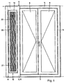
- Im folgenden wird die Erfindung anhand von Figuren, welche lediglich ein Ausführungsbeispiel darstellen, näher erläutert. Es zeigen
- Fig. 1
- einen erfindungsgemässen Fensterbereich von innen,
- Fig. 2
- einen horizontalen Schnitt durch den Fensterbereich gemäss
Fig. 1 , - Fig. 3
- einen vertikalen Schnitt durch den Fensterbereich gemäss
Fig. 1 ,2 , - Fig. 4
- einen horizontalen Schnitt entsprechend
Fig. 2 durch einen abgewandelten erfindungsgemässen Fensterbereich und - Fig. 5
- einen vertikalen Schnitt entsprechend
Fig. 3 durch den abgewandelten Fensterbereich vonFig. 4 . - Der erfindungsgemässe Fensterbereich umfasst (
Fig. 1-3 ) eine Aussendämmung 1, welche vorzugsweise aus einem festen wärmeisolierenden Material wie z.B. aus Stypropor oder Mineralwolle besteht und eine im wesentlichen durchgehende, eine Fassade bedeckende vertikale Schicht konstanter Dicke bildet, die gewöhnlich an der Aussenseite einer Wand 2, die z.B. gemauert oder betoniert sein kann, angeordnet ist und aussen von einer mit kleinem Abstand vorgeordneten hinterlüfteten Aussenverkleidung 3, welche z.B. aus Holz, Naturstein oder Aluminium besteht, bedeckt ist. In der Aussendämmung 1 ist eine rechteckige Fensteröffnung 4 ausgespart, in der ein Fensterrahmen 5 angeordnet ist, welcher die Fensteröffnung 4 an der Innenseite umrahmt. Im Bereich einer die Fensteröffnung 4 umgebenden Leibung 6 ist die Aussendämmung 1 ebenfalls von der Aussenverkleidung 3 verdeckt, in der dort ein Rolladen 7 geführt ist. Am Fensterrahmen 5 sind zwei Fensterflügel 8 angeschlagen, die nach innen geschwenkt werden können. - Neben dem Fensterrahmen 5 ist eine schmale, ebenfalls rechteckige Verkleidung 9 angebracht, welche die Innenseite der Aussendämmung 1 zwischen dem Fensterrahmen 5 und der etwas weiter als die Aussendämmung 1 ausgeschnittenen Wand 2 bedeckt. Die Verkleidung 9 umfasst eine Platte 10 und einen dieselbe z.T. umgebenden, z.T. bedeckenden, rundum etwas vorspringenden Rahmen 11, der teilweise mit einem Seitenteil des Fensterrahmens 5 zusammenfallen kann und eine flache rechteckige Vertiefung 12 umgibt, deren Grund von der Platte 10 gebildet wird. Der Fensterrahmen 5 und die Verkleidung 9 können aus Holz bestehen.
- In der Nähe des oberen Endes der Vertiefung 12 ist in der Platte 10 eine innere Zuluftöffnung 13 angeordnet, an welche eine Zuluftleitung 14 anschliesst, die horizontal und um 90° gebogen durch die Aussendämmung 1 zu einer schlitzförmigen äusseren Zuluftöffnung 15 in der Aussenverkleidung 3 an der Leibung 6 führt. In der Nähe des unteren Endes der Vertiefung 12, also vertikal von der inneren Zuluftöffnung 13 beabstandet, ist in der Platte 10 eine entsprechende innere Abluftöffnung 16 angeordnet, von der eine Abluftleitung 17 horizontal und gerade durch die Aussendämmung 1 zu einer äusseren Abluftöffnung 18 an deren Aussenseite führt. Die Abluftleitung 17 mündet somit in den Spalt zwischen der Aussendämmung 1 und der Aussenverkleidung 3.
- In die Vertiefung 12 ist passgenau ein Lüfter 19 eingesetzt mit einem quaderförmigen Gehäuse von ungefähr quadratischem Grundriss, dessen Höhe ganz oder annähernd der der Fensterflügel 8 entspricht. Er weist an seiner in der Vertiefung 12 liegenden Rückseite einen Zulufteinlass auf, der sich mit der inneren Zuluftöffnung 13 deckt und einen Abluftauslass, der sich mit der inneren Abluftöffnung 16 deckt. An der Vorderseite weist er hinter einem Gitter 20 einen Zuluftauslass 21 auf, der etwa auf der Höhe des Abluftauslasses liegt sowie darüber, also vertikal versetzt, einen Ablufteinlass 22 etwa auf der Höhe des Zulufteinlasses. Der Ablufteinlass 22 des Lüfters 19 ist mit dem Abluftauslass durch einen Abluftkanal verbunden, welcher mit einem den Zulufteinlass mit dem Zuluftauslass 21 verbindenden Zuluftkanal einen Wärmetauscher bildet. In mindestens einem der beiden Kanäle ist ein Ventilator vorgesehen, der eine Luftströmung vom Einlass zum Auslass erzeugt, sodass Frischluft über die Zuluftleitung 14 an der äusseren Zuluftöffnung 15 angesaugt und schliesslich am Zuluftauslass 21 in den Raum abgegeben wird, während Abluft durch den Ablufteinlass 22 aus dem Raum abgezogen und über die Abluftleitung 17 der äusseren Abluftöffnung 18 zugeführt und dort nach aussen abgegeben wird. Es sind zahlreiche Lüfter bekannt, die hier zum Einsatz kommen können. Z.B. kann der Lüfter 19 im wesentlichen wie die in
EP 1 510 764 A1 beschriebene Lüftungseinrichtung aufgebaut sein, wobei allenfalls die Lage der Ein- und Auslässe betreffende Anpassungen durch eine Ergänzung oder Aenderung des Zuluft- und des Abluftkanals vorgenommen werden müssen. - Durch die vertikale Versetzung des Zuluftauslasses 21 und des Ablufteinlasses 22 ist unerwünschte Vermischung, also sofortiges Wiederabziehen eines Teils der eben eingeleiteten Zuluft auf ein nicht störendes Ausmass reduziert. An der Aussenseite sind die äussere Zuluftöffnung 15 und die äussere Abluftöffnung 18 ausser durch die vertikale Versetzung noch dadurch getrennt, dass die erstere in der Aussenverkleidung 3 im Bereich der Leibung 6 angebracht ist und die letztere hinter der Aussenverkleidung 3 an der Aussenseite der Aussendämmung 1 liegt. Eine in diesem Fall besonders störende Vermischung von Abluft und Zuluft - sofortiges Wiederzuführen eines Teils der eben abgeleiteten Abluft als Zuluft - ist daher so gut wie vollständig unterbunden.
- Durch den Lüfter 19 wird nicht nur Zuluft zu- und Abluft abgeführt, es wird auch die Temperatur der Zuluft an diejenige der Abluft, also die Temperatur des oft geheizten oder auch gekühlten Raumes angenähert und dadurch eine u.U. beträchtliche Energieeinsparung erzielt.
- Falls jedoch kein Lüfter eingesetzt werden soll, so kann (
Fig. 4, 5 ) in die Vertiefung 12 stattdessen einfach eine passgenaue rechteckige Verschlussplatte 23 eingesetzt werden, die die innere Zuluftöffnung 13 und die innere Abluftöffnung 16 vom Raum trennt. Vorzugsweise sind der Lüfter 19 und die Verschlussplatte 23 auf gleiche Weise mit der Verkleidung 9 reversibel verbindbar, z.B. verschraubbar, sodass sie auch nach Fertigstellung des Gebäudes leicht ausgetauscht werden können. -
- 1
- Aussendämmung
- 2
- Wand
- 3
- Aussenverkleidung
- 4
- Fensteröffnung
- 5
- Fensterrahmen
- 6
- Leibung
- 7
- Rolladen
- 8
- Fensterflügel
- 9
- Verkleidung
- 10
- Platte
- 11
- Rahmen
- 12
- Vertiefung
- 13
- innere Zuluftöffnung
- 14
- Zuluftleitung
- 15
- äussere Zuluftöffnung
- 16
- innere Abluftöffnung
- 17
- Abluftleitung
- 18
- äussere Abluftöffnung
- 19
- Lüfter
- 20
- Gitter
- 21
- Zuluftauslass
- 22
- Ablufteinlass
- 23
- Verschlussplatte
Claims (10)
- Fensterbereich mit einer Wand (2) und einer an deren Aussenseite angeordneten Aussendämmung (1), welche von einer Fensteröffnung (4) durchbrochen sind und einem die Fensteröffnung (4) umgebenden Fensterrahmen (5), dadurch gekennzeichnet, dass die Wand (2) etwas weiter ausgeschnitten ist, sodass eine Innenseite der Aussendämmung (1) in einem Bereich seitlich neben dem Fensterrahmen (5) von der Wand (2) frei ist und dort an der besagten Innenseite eine innere Zuluftöffnung (13) und eine innere Abluftöffnung (16) angeordnet sind, welche jeweils mittels einer durch die Aussendämmung (1) geführten Zuluftleitung (14) bzw. Abluftleitung (17) mit einer ausserhalb des Fensterrahmens (5) angeordneten äusseren Zuluftöffnung (15) bzw. äusseren Abluftöffnung (18) verbunden sind.
- Fensterbereich nach Anspruch 1, dadurch gekennzeichnet, dass die innere Zuluftöffnung (13) und die innere Abluftöffnung (16) in einer an den Fensterrahmen (5) anschliessenden, dort die Innenseite der Aussendämmung (1) bedeckenden Verkleidung (9) liegen.
- Fensterbereich nach Anspruch 2, dadurch gekennzeichnet, dass die innere Zuluftöffnung (13) und die innere Abluftöffnung (16) in einer Vertiefung (12) der Verkleidung (9) angeordnet sind.
- Fensterbereich nach einem der Ansprüche 1 bis 3, dadurch gekennzeichnet, dass die innere Zuluftöffnung (13) und die innere Abluftöffnung (16) vertikal voneinander beabstandet sind.
- Fensterbereich nach einem der Ansprüche 1 bis 4, dadurch gekennzeichnet, dass die äussere Zuluftöffnung (15) an der Leibung (6) der Fensteröffnung (4) liegt, während die äussere Abluftöffnung (18) an der der Innenseite gegenüberliegenden Aussenseite der Aussendämmung (1) liegt oder umgekehrt.
- Fensterbereich nach einem der Ansprüche 1 bis 5, dadurch gekennzeichnet, dass die Zuluftleitung (14) und die Abluftleitung (17) jeweils horizontal durch die Aussendämmung (1) geführt sind.
- Fensterbereich nach einem der Ansprüche 1 bis 6, dadurch gekennzeichnet, dass sie einen neben dem Fensterrahmen (5) angeordneten Lüfter (19) umfasst mit einem an die innere Zuluftöffnung (13) anschliessenden Zulufteinlass und einem über einen Zuluftkanal mit demselben verbundenen Zuluftauslass (21) sowie einem an die innere Abluftöffnung (16) anschliessenden Abluftauslass und einem über einen Abluftkanal mit demselben verbundenen Ablufteinlass (22), wobei der Zuluftkanal und der Abluftkanal einen Wärmetauscher bilden.
- Fensterbereich nach Anspruch 7, dadurch gekennzeichnet, dass der Lüfter (19) mindestens im Zuluftkanal oder im Abluftkanal einen Ventilator aufweist.
- Fensterbereich nach Anspruch 3 und Anspruch 7 oder 8, dadurch gekennzeichnet, dass der Lüfter (19) mit einer Rückwand in die Vertiefung (12) der Verkleidung (9) eingesetzt ist.
- Fensterbereich nach einem der Ansprüche 7 bis 9, dadurch gekennzeichnet, dass der Zuluftauslass (21) und der Ablufteinlass (22) vertikal voneinander beabstandet an einer Vorderseite des Lüfters (19) angeordnet sind.
Priority Applications (2)
| Application Number | Priority Date | Filing Date | Title |
|---|---|---|---|
| EP06405132.9A EP1840478B1 (de) | 2006-03-29 | 2006-03-29 | Fensterbereich |
| US11/728,323 US20070240372A1 (en) | 2006-03-29 | 2007-03-23 | Window area |
Applications Claiming Priority (1)
| Application Number | Priority Date | Filing Date | Title |
|---|---|---|---|
| EP06405132.9A EP1840478B1 (de) | 2006-03-29 | 2006-03-29 | Fensterbereich |
Publications (2)
| Publication Number | Publication Date |
|---|---|
| EP1840478A1 EP1840478A1 (de) | 2007-10-03 |
| EP1840478B1 true EP1840478B1 (de) | 2016-02-17 |
Family
ID=36910827
Family Applications (1)
| Application Number | Title | Priority Date | Filing Date |
|---|---|---|---|
| EP06405132.9A Expired - Lifetime EP1840478B1 (de) | 2006-03-29 | 2006-03-29 | Fensterbereich |
Country Status (2)
| Country | Link |
|---|---|
| US (1) | US20070240372A1 (de) |
| EP (1) | EP1840478B1 (de) |
Families Citing this family (6)
| Publication number | Priority date | Publication date | Assignee | Title |
|---|---|---|---|---|
| KR101238125B1 (ko) * | 2007-12-29 | 2013-02-27 | (주)엘지하우시스 | 통기구조를 적용한 이중 창호 |
| FR2930322B1 (fr) * | 2008-04-17 | 2010-07-30 | Electricite De France | Dispositif d'extraction d'air. |
| US20140034274A1 (en) * | 2010-07-01 | 2014-02-06 | Melvin E. Shaffer | Air Barrier |
| DE102012104198A1 (de) * | 2012-05-14 | 2013-11-14 | Hautau Gmbh | Rahmenlüftungsgerät, Fensteranordnung und eingebautes Fenster mit Lüftungsgerät zum Lüften und zum Erhalt der regulären Verglasungsgröße und auch Rahmenmaße |
| DE102014101544A1 (de) | 2014-02-07 | 2015-08-13 | Beck & Heun Gmbh | Fensterkomplettmodul, integriertes Lüftungsmodul sowie Dämmelement |
| CN106050095B (zh) * | 2016-06-13 | 2017-07-21 | 朱幕松 | 新风空气净化器 |
Family Cites Families (12)
| Publication number | Priority date | Publication date | Assignee | Title |
|---|---|---|---|---|
| DE3200114A1 (de) * | 1981-05-07 | 1983-10-20 | Günter Dipl.-Architekt 6096 Raunheim Hack | Lueftungseinrichtung in der fensterwand von gebaeuden |
| DE8224454U1 (de) * | 1982-08-30 | 1982-11-25 | Siegenia-Frank Kg, 5900 Siegen | Lueftungsvorrichtung zur anordnung an gebaeudewaenden |
| FI73044C (fi) * | 1983-11-09 | 1988-05-17 | Partek Ab | Foenster. |
| JPS6120774U (ja) * | 1984-07-10 | 1986-02-06 | ワイケイケイ株式会社 | 換気装置付出窓 |
| GB2218799A (en) * | 1988-05-17 | 1989-11-22 | Diffusion Environmental System | Sound attenuating ventilator |
| DE4343107C2 (de) * | 1993-12-17 | 1999-05-27 | Fsl Fenster System Lueftung | Lüftungssystem |
| DE4435064A1 (de) * | 1994-09-30 | 1996-04-04 | Eberhard Dipl Ing Paul | Luftführ- und Luftförderelemente für Gebäudebelüftung in Kombination mit Wärmerückgewinnungsgeräten |
| US5822933A (en) * | 1997-01-23 | 1998-10-20 | Advanced Construction Technologies, Inc. | Method and apparatus for wall drainage |
| DE10010817A1 (de) * | 2000-03-08 | 2001-10-18 | Mig Mittelstands Entwicklungsg | Raumlüftungsvorrichtung |
| CA2355432A1 (en) * | 2001-08-16 | 2003-02-16 | Stephen Field | Window and wall assembly |
| US7607267B2 (en) * | 2002-10-04 | 2009-10-27 | Bovard Studio, Inc | Apparatus for venting of protective panels |
| EP1486637B1 (de) * | 2003-06-12 | 2009-08-05 | Lidartech Co., Ltd. | Fenster mit Lüftungsvorrichtung |
-
2006
- 2006-03-29 EP EP06405132.9A patent/EP1840478B1/de not_active Expired - Lifetime
-
2007
- 2007-03-23 US US11/728,323 patent/US20070240372A1/en not_active Abandoned
Also Published As
| Publication number | Publication date |
|---|---|
| US20070240372A1 (en) | 2007-10-18 |
| EP1840478A1 (de) | 2007-10-03 |
Similar Documents
| Publication | Publication Date | Title |
|---|---|---|
| EP2594725B1 (de) | Fenster | |
| DE19548599C2 (de) | Lüftungssystem für die Räume von Gebäuden | |
| DE19859851B4 (de) | Brandschutzsystem | |
| DE102008020941B4 (de) | Luftführungselement zum Zuführen und/oder Abführen von Luft | |
| EP1840478A1 (de) | Fensterbereich | |
| EP3168545A1 (de) | Luftschleieranlage | |
| DE20218457U1 (de) | Einrichtung zur Zufuhr von Außenluft in den Bereich eine Heizkörpers | |
| DE102015101510A1 (de) | Fassadenanschlusseinrichtung für eine Lüftungseinrichtung sowie Lüftungseinrichtung | |
| DE19908571C2 (de) | Rolladenaggregat | |
| DE212011100069U1 (de) | Türöffnung zwischen zwei Räumen | |
| DE102016103950B4 (de) | Anordnung zur Be- und Entlüftung von Räumen im Bereich eines Fensters | |
| EP2708827A2 (de) | Luftaus- oder -einlass und Lüftungssystem hiermit | |
| DE202019100467U1 (de) | Lufteinlass und Anordnung zur Führung von Luft | |
| EP2698497B1 (de) | Fensteranordnung mit einem Innenfutter | |
| DE3785188T2 (de) | Lüftungsvorrichtung. | |
| EP1577618A2 (de) | Fassadenelement zum aussenseitigen Abschluss von Zu- und Abluftöffnungen in Aussenwänden | |
| DE1801852A1 (de) | Lueftungs- oder Klimaanlage | |
| DE2854267A1 (de) | Brandschutzsicherung | |
| DE3145508C2 (de) | Lüftungskanal zur Be- und/oder Entlüftung eines Raumes | |
| DE3806903C2 (de) | Verfahren zur Klimatisierung von Räumen sowie Klimatisierungssystem zur Durchführung des Verfahrens | |
| EP2431679B1 (de) | System zur Raumbelüftung | |
| DE3013440A1 (de) | Fenster oder tuer mit integrierter lueftungsvorrichtung | |
| DE4222987A1 (de) | Anordnung zur Be- und Entlüftung in Außenwandelementen | |
| DE102006024803A1 (de) | Anschlussvorrichtung | |
| DE3900031C1 (en) | Weather protection grating for a rear-ventilation gap |
Legal Events
| Date | Code | Title | Description |
|---|---|---|---|
| PUAI | Public reference made under article 153(3) epc to a published international application that has entered the european phase |
Free format text: ORIGINAL CODE: 0009012 |
|
| AK | Designated contracting states |
Kind code of ref document: A1 Designated state(s): AT BE BG CH CY CZ DE DK EE ES FI FR GB GR HU IE IS IT LI LT LU LV MC NL PL PT RO SE SI SK TR |
|
| AX | Request for extension of the european patent |
Extension state: AL BA HR MK YU |
|
| 17P | Request for examination filed |
Effective date: 20080313 |
|
| 17Q | First examination report despatched |
Effective date: 20080424 |
|
| AKX | Designation fees paid |
Designated state(s): AT BE BG CH CY CZ DE DK EE ES FI FR GB GR HU IE IS IT LI LT LU LV MC NL PL PT RO SE SI SK TR |
|
| GRAP | Despatch of communication of intention to grant a patent |
Free format text: ORIGINAL CODE: EPIDOSNIGR1 |
|
| INTG | Intention to grant announced |
Effective date: 20150730 |
|
| GRAS | Grant fee paid |
Free format text: ORIGINAL CODE: EPIDOSNIGR3 |
|
| INTG | Intention to grant announced |
Effective date: 20151209 |
|
| GRAA | (expected) grant |
Free format text: ORIGINAL CODE: 0009210 |
|
| AK | Designated contracting states |
Kind code of ref document: B1 Designated state(s): AT BE BG CH CY CZ DE DK EE ES FI FR GB GR HU IE IS IT LI LT LU LV MC NL PL PT RO SE SI SK TR |
|
| REG | Reference to a national code |
Ref country code: GB Ref legal event code: FG4D Free format text: NOT ENGLISH |
|
| REG | Reference to a national code |
Ref country code: CH Ref legal event code: EP |
|
| REG | Reference to a national code |
Ref country code: IE Ref legal event code: FG4D Free format text: LANGUAGE OF EP DOCUMENT: GERMAN |
|
| REG | Reference to a national code |
Ref country code: AT Ref legal event code: REF Ref document number: 775838 Country of ref document: AT Kind code of ref document: T Effective date: 20160315 Ref country code: CH Ref legal event code: NV Representative=s name: WAGNER PATENT AG, CH |
|
| REG | Reference to a national code |
Ref country code: DE Ref legal event code: R096 Ref document number: 502006014755 Country of ref document: DE |
|
| REG | Reference to a national code |
Ref country code: NL Ref legal event code: FP |
|
| REG | Reference to a national code |
Ref country code: LT Ref legal event code: MG4D |
|
| PG25 | Lapsed in a contracting state [announced via postgrant information from national office to epo] |
Ref country code: ES Free format text: LAPSE BECAUSE OF FAILURE TO SUBMIT A TRANSLATION OF THE DESCRIPTION OR TO PAY THE FEE WITHIN THE PRESCRIBED TIME-LIMIT Effective date: 20160217 Ref country code: FI Free format text: LAPSE BECAUSE OF FAILURE TO SUBMIT A TRANSLATION OF THE DESCRIPTION OR TO PAY THE FEE WITHIN THE PRESCRIBED TIME-LIMIT Effective date: 20160217 Ref country code: GR Free format text: LAPSE BECAUSE OF FAILURE TO SUBMIT A TRANSLATION OF THE DESCRIPTION OR TO PAY THE FEE WITHIN THE PRESCRIBED TIME-LIMIT Effective date: 20160518 Ref country code: IT Free format text: LAPSE BECAUSE OF FAILURE TO SUBMIT A TRANSLATION OF THE DESCRIPTION OR TO PAY THE FEE WITHIN THE PRESCRIBED TIME-LIMIT Effective date: 20160217 |
|
| PG25 | Lapsed in a contracting state [announced via postgrant information from national office to epo] |
Ref country code: BE Free format text: LAPSE BECAUSE OF NON-PAYMENT OF DUE FEES Effective date: 20160331 Ref country code: PT Free format text: LAPSE BECAUSE OF FAILURE TO SUBMIT A TRANSLATION OF THE DESCRIPTION OR TO PAY THE FEE WITHIN THE PRESCRIBED TIME-LIMIT Effective date: 20160617 Ref country code: PL Free format text: LAPSE BECAUSE OF FAILURE TO SUBMIT A TRANSLATION OF THE DESCRIPTION OR TO PAY THE FEE WITHIN THE PRESCRIBED TIME-LIMIT Effective date: 20160217 Ref country code: LV Free format text: LAPSE BECAUSE OF FAILURE TO SUBMIT A TRANSLATION OF THE DESCRIPTION OR TO PAY THE FEE WITHIN THE PRESCRIBED TIME-LIMIT Effective date: 20160217 Ref country code: LT Free format text: LAPSE BECAUSE OF FAILURE TO SUBMIT A TRANSLATION OF THE DESCRIPTION OR TO PAY THE FEE WITHIN THE PRESCRIBED TIME-LIMIT Effective date: 20160217 Ref country code: SE Free format text: LAPSE BECAUSE OF FAILURE TO SUBMIT A TRANSLATION OF THE DESCRIPTION OR TO PAY THE FEE WITHIN THE PRESCRIBED TIME-LIMIT Effective date: 20160217 |
|
| PG25 | Lapsed in a contracting state [announced via postgrant information from national office to epo] |
Ref country code: DK Free format text: LAPSE BECAUSE OF FAILURE TO SUBMIT A TRANSLATION OF THE DESCRIPTION OR TO PAY THE FEE WITHIN THE PRESCRIBED TIME-LIMIT Effective date: 20160217 Ref country code: EE Free format text: LAPSE BECAUSE OF FAILURE TO SUBMIT A TRANSLATION OF THE DESCRIPTION OR TO PAY THE FEE WITHIN THE PRESCRIBED TIME-LIMIT Effective date: 20160217 |
|
| REG | Reference to a national code |
Ref country code: DE Ref legal event code: R097 Ref document number: 502006014755 Country of ref document: DE |
|
| PG25 | Lapsed in a contracting state [announced via postgrant information from national office to epo] |
Ref country code: CZ Free format text: LAPSE BECAUSE OF FAILURE TO SUBMIT A TRANSLATION OF THE DESCRIPTION OR TO PAY THE FEE WITHIN THE PRESCRIBED TIME-LIMIT Effective date: 20160217 Ref country code: SK Free format text: LAPSE BECAUSE OF FAILURE TO SUBMIT A TRANSLATION OF THE DESCRIPTION OR TO PAY THE FEE WITHIN THE PRESCRIBED TIME-LIMIT Effective date: 20160217 Ref country code: RO Free format text: LAPSE BECAUSE OF FAILURE TO SUBMIT A TRANSLATION OF THE DESCRIPTION OR TO PAY THE FEE WITHIN THE PRESCRIBED TIME-LIMIT Effective date: 20160217 |
|
| PLBE | No opposition filed within time limit |
Free format text: ORIGINAL CODE: 0009261 |
|
| STAA | Information on the status of an ep patent application or granted ep patent |
Free format text: STATUS: NO OPPOSITION FILED WITHIN TIME LIMIT |
|
| REG | Reference to a national code |
Ref country code: IE Ref legal event code: MM4A |
|
| REG | Reference to a national code |
Ref country code: FR Ref legal event code: ST Effective date: 20161130 |
|
| 26N | No opposition filed |
Effective date: 20161118 |
|
| GBPC | Gb: european patent ceased through non-payment of renewal fee |
Effective date: 20160517 |
|
| PG25 | Lapsed in a contracting state [announced via postgrant information from national office to epo] |
Ref country code: IE Free format text: LAPSE BECAUSE OF NON-PAYMENT OF DUE FEES Effective date: 20160329 Ref country code: FR Free format text: LAPSE BECAUSE OF NON-PAYMENT OF DUE FEES Effective date: 20160418 |
|
| PG25 | Lapsed in a contracting state [announced via postgrant information from national office to epo] |
Ref country code: BG Free format text: LAPSE BECAUSE OF FAILURE TO SUBMIT A TRANSLATION OF THE DESCRIPTION OR TO PAY THE FEE WITHIN THE PRESCRIBED TIME-LIMIT Effective date: 20160517 Ref country code: SI Free format text: LAPSE BECAUSE OF FAILURE TO SUBMIT A TRANSLATION OF THE DESCRIPTION OR TO PAY THE FEE WITHIN THE PRESCRIBED TIME-LIMIT Effective date: 20160217 |
|
| PG25 | Lapsed in a contracting state [announced via postgrant information from national office to epo] |
Ref country code: GB Free format text: LAPSE BECAUSE OF NON-PAYMENT OF DUE FEES Effective date: 20160517 |
|
| PGFP | Annual fee paid to national office [announced via postgrant information from national office to epo] |
Ref country code: NL Payment date: 20180321 Year of fee payment: 13 |
|
| PG25 | Lapsed in a contracting state [announced via postgrant information from national office to epo] |
Ref country code: HU Free format text: LAPSE BECAUSE OF FAILURE TO SUBMIT A TRANSLATION OF THE DESCRIPTION OR TO PAY THE FEE WITHIN THE PRESCRIBED TIME-LIMIT; INVALID AB INITIO Effective date: 20060329 Ref country code: CY Free format text: LAPSE BECAUSE OF FAILURE TO SUBMIT A TRANSLATION OF THE DESCRIPTION OR TO PAY THE FEE WITHIN THE PRESCRIBED TIME-LIMIT Effective date: 20160217 |
|
| PGFP | Annual fee paid to national office [announced via postgrant information from national office to epo] |
Ref country code: AT Payment date: 20180322 Year of fee payment: 13 |
|
| PG25 | Lapsed in a contracting state [announced via postgrant information from national office to epo] |
Ref country code: LU Free format text: LAPSE BECAUSE OF NON-PAYMENT OF DUE FEES Effective date: 20160329 Ref country code: TR Free format text: LAPSE BECAUSE OF FAILURE TO SUBMIT A TRANSLATION OF THE DESCRIPTION OR TO PAY THE FEE WITHIN THE PRESCRIBED TIME-LIMIT Effective date: 20160217 Ref country code: MC Free format text: LAPSE BECAUSE OF FAILURE TO SUBMIT A TRANSLATION OF THE DESCRIPTION OR TO PAY THE FEE WITHIN THE PRESCRIBED TIME-LIMIT Effective date: 20160217 Ref country code: IS Free format text: LAPSE BECAUSE OF FAILURE TO SUBMIT A TRANSLATION OF THE DESCRIPTION OR TO PAY THE FEE WITHIN THE PRESCRIBED TIME-LIMIT Effective date: 20160217 |
|
| REG | Reference to a national code |
Ref country code: NL Ref legal event code: MM Effective date: 20190401 |
|
| REG | Reference to a national code |
Ref country code: AT Ref legal event code: MM01 Ref document number: 775838 Country of ref document: AT Kind code of ref document: T Effective date: 20190329 |
|
| PG25 | Lapsed in a contracting state [announced via postgrant information from national office to epo] |
Ref country code: NL Free format text: LAPSE BECAUSE OF NON-PAYMENT OF DUE FEES Effective date: 20190401 Ref country code: AT Free format text: LAPSE BECAUSE OF NON-PAYMENT OF DUE FEES Effective date: 20190329 |
|
| PGFP | Annual fee paid to national office [announced via postgrant information from national office to epo] |
Ref country code: DE Payment date: 20230323 Year of fee payment: 18 |
|
| PGFP | Annual fee paid to national office [announced via postgrant information from national office to epo] |
Ref country code: CH Payment date: 20240401 Year of fee payment: 19 |
|
| REG | Reference to a national code |
Ref country code: DE Ref legal event code: R119 Ref document number: 502006014755 Country of ref document: DE |
|
| PG25 | Lapsed in a contracting state [announced via postgrant information from national office to epo] |
Ref country code: DE Free format text: LAPSE BECAUSE OF NON-PAYMENT OF DUE FEES Effective date: 20241001 |
|
| PG25 | Lapsed in a contracting state [announced via postgrant information from national office to epo] |
Ref country code: DE Free format text: LAPSE BECAUSE OF NON-PAYMENT OF DUE FEES Effective date: 20241001 |
|
| REG | Reference to a national code |
Ref country code: CH Ref legal event code: H13 Free format text: ST27 STATUS EVENT CODE: U-0-0-H10-H13 (AS PROVIDED BY THE NATIONAL OFFICE) Effective date: 20251024 |
|
| PG25 | Lapsed in a contracting state [announced via postgrant information from national office to epo] |
Ref country code: CH Free format text: LAPSE BECAUSE OF NON-PAYMENT OF DUE FEES Effective date: 20250331 |