EP1840397B1 - Arbre de commande pour un mécanisme à mise au point - Google Patents
Arbre de commande pour un mécanisme à mise au point Download PDFInfo
- Publication number
- EP1840397B1 EP1840397B1 EP06025170A EP06025170A EP1840397B1 EP 1840397 B1 EP1840397 B1 EP 1840397B1 EP 06025170 A EP06025170 A EP 06025170A EP 06025170 A EP06025170 A EP 06025170A EP 1840397 B1 EP1840397 B1 EP 1840397B1
- Authority
- EP
- European Patent Office
- Prior art keywords
- shaft
- piece
- selector shaft
- securing element
- selector
- Prior art date
- Legal status (The legal status is an assumption and is not a legal conclusion. Google has not performed a legal analysis and makes no representation as to the accuracy of the status listed.)
- Active
Links
Images

Classifications
-
- F—MECHANICAL ENGINEERING; LIGHTING; HEATING; WEAPONS; BLASTING
- F16—ENGINEERING ELEMENTS AND UNITS; GENERAL MEASURES FOR PRODUCING AND MAINTAINING EFFECTIVE FUNCTIONING OF MACHINES OR INSTALLATIONS; THERMAL INSULATION IN GENERAL
- F16D—COUPLINGS FOR TRANSMITTING ROTATION; CLUTCHES; BRAKES
- F16D1/00—Couplings for rigidly connecting two coaxial shafts or other movable machine elements
- F16D1/02—Couplings for rigidly connecting two coaxial shafts or other movable machine elements for connecting two abutting shafts or the like
- F16D1/04—Couplings for rigidly connecting two coaxial shafts or other movable machine elements for connecting two abutting shafts or the like with clamping hub; with hub and longitudinal key
-
- H—ELECTRICITY
- H01—ELECTRIC ELEMENTS
- H01H—ELECTRIC SWITCHES; RELAYS; SELECTORS; EMERGENCY PROTECTIVE DEVICES
- H01H33/00—High-tension or heavy-current switches with arc-extinguishing or arc-preventing means
- H01H33/02—Details
- H01H33/42—Driving mechanisms
Definitions
- the invention relates to a switching shaft for an electrical switching device, in particular for high voltage and / or medium voltage systems with the features of the preamble of claim 1.
- Such a switching shaft is known from U.S.-A-3,606,407 ,
- Such switching shafts are used for electrical switching devices to close or interrupt electrical contacts.
- the switching shaft is rotated by means of a drive for switching the switching device.
- Individual sections of the shift shaft have a respective output assigned to an electrical contact. Each output cooperates with a contact point, so that several contacts can be switched simultaneously upon rotation of the shift shaft.
- the known shift shaft has a plurality of sections, so that the above-described arrangement is easier to assemble.
- Shifter shafts In this case, shaft pieces are used, with which mutually adjacent sections of the switching shaft can be interconnected.
- Shifter shafts is a rotational force transmitted from the end portion of a portion of a sleeve, from this sleeve on said shaft piece, from this shaft piece to another sleeve, and finally from the latter sleeve to an end portion of an adjacent portion of the switching shaft.
- Such a switching shaft allows the connection of the adjacent portions of the switching shaft by a securing element.
- the securing element is designed in two parts and displaceable along the shaft piece. Furthermore, there is a locking pin to achieve a fixed angular position between the securing element and the shaft.
- the present invention seeks to provide a switching shaft for an electrical switching device, which takes up less space, the power transmission is optimized and the assembly of the shift shaft is simplified.
- overlapping end portions can be saved in the axial direction of space.
- the shaft piece is in overlapping engagement with the end portion of an adjacent portion of the shift shaft at at least one of its ends. Extra space can be saved if this type of connection of shaft piece and adjacent sections of the switching shaft at both ends of the shaft piece is provided.
- a rotational force is optimized over the prior art in that force can be transmitted directly from one section of the switching shaft to the adjacent shaft section with the aid of the overlapping end regions.
- a rotational force can be introduced from one section into a shaft section and from there directly into the end section of an adjacent section of the control shaft.
- a power coupling of shaft and sections of the shift shaft is thus directly, d. H. without the interposition of sleeves, as is known from the prior art.
- the advantage is further achieved that a possibility is provided by the angular position of the ends of the shaft piece and the engaging ends of the portions of the shift shaft, to determine the angular position of the two sections of the shift shaft to each other. This allows degrees of freedom with regard to the design of the drive as well as of the output and the contact points arranged in the region of the output.
- a fuse element is provided.
- Such a securing element need not, as known from the prior art, transmit a rotational force from a portion of the switching shaft to a shaft piece. Instead, the backup element is used only for backup purposes. This makes it possible to add the end portions of a shaft piece with the end portions of adjacent portions of the shift shaft and then secure the overlapping end portions with the securing element.
- the shaft piece and the securing element in the direction of rotation of Shift shaft are mutually positive. This can be achieved for example by a non-rotationally symmetrical cross-sectional profile of the shaft piece and the securing element.
- the one-piece design of a securing element for securing a shaft piece and a sleeve and the ability to move the securing element along the shaft piece facilitate the assembly of the shaft piece.
- the securing element In a pre-assembly state, the securing element is fixed on the shaft piece, transported in this state and then pushed during assembly over the sleeve and fixed again. This reduces the assembly effort, since, for example, no multi-part fuse element must be merged to be fixed.
- the positive engagement of fuse element and shaft in the direction of rotation also facilitates assembly, since the fuse element in the pre-assembly as well as in the final assembly is not rotatable in the direction of rotation, but can only be moved along the shaft section.
- An adjustment in the direction of rotation of the shaft piece is thus already given by the shape of fuse element and shaft piece.
- the securing element is thus always in the correct position to be fixed, shifted to the corresponding point of the shaft piece.
- one of the end regions has a receptacle in which the other end region is accommodated.
- these embodiments can also be combined with each other for a shift shaft.
- one of the end regions has two mutually parallel force transmission surfaces which cooperate with two associated force receiving surfaces of the other end region.
- the shaft piece and a portion of the switching shaft can be joined together in a simple manner by the power transmission surfaces and the force receiving surfaces are aligned parallel to each other and then the shaft portion and a portion of the switching shaft can be joined together in a direction perpendicular to the shaft axis, until the power transmission surfaces and the force receiving surfaces overlap each other.
- a particularly advantageous embodiment provides that the force transmission surfaces or the force receiving surfaces in a plane parallel to the shaft axis border on a material portion which forms a stop surface for the other end region.
- the above-described assembly of the shaft piece and at least a portion of the shift shaft can be facilitated to the effect that the stop surface defines the relative position of shaft portion and at least a portion of the shift shaft in a direction perpendicular to the shaft axis.
- the stop surface is offset from the shaft axis. This makes it possible, a torque largely centrally, d. H. in the region of the shaft axis of a portion of the switching shaft on a shaft piece and to be able to transmit this to an adjacent portion of the switching shaft.
- the function of the securing element can be limited within the scope of this invention to secure said elements together. This can be done in a simple manner in that the securing element is annular and thus surrounds the overlapping end portions of the shaft piece or a portion of the switching shaft.
- the securing element does not have to ensure transmission of rotational forces, and therefore does not have to have corresponding force introduction and force discharge areas, it can be constructed comparatively quickly.
- the securing element in the direction of the shaft axis is equal to or shorter than the dimension with which the end regions overlap. In this way, more space and material can be saved.
- the invention further relates to an electrical switching device, in particular for high-voltage and / or medium-voltage systems, with a switching shaft described above.
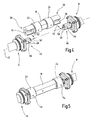
- a shift shaft according to the invention is designated overall by the reference numeral 2. This can be offset by means of an unspecified and known per se drive 4 in a rotary motion.
- the switching shaft 2 has three sections 6, 8 and 10, wherein each section an output 12, 14 and 16 is associated. These drives are in connection with contacts to be switched. Upon rotation of the shift shaft 2 by means of the drive 4 so at the same time the outputs 12, 14 and 16 actuated so that downstream switching contacts can be switched simultaneously.
- the sections 6 and 8 of the switching shaft 2 are connected to each other via a shaft piece 18.
- the sections 8 and 10 of the switching shaft 2 are connected to each other via a shaft piece 20.
- To secure the shaft piece 18 at the sections 6 and 8 securing elements 22 and 24 are provided.
- To secure the shaft piece 20 at the sections 8 and 10 securing elements 26 and 28 are provided.
- FIG. 2 shows an enlarged view of the shaft piece 18.
- the shaft piece 20 has a corresponding structure.
- the shaft piece 18 has a left hand illustrated end portion 30 and a right hand end portion 32 shown.
- receptacles 34 are provided, which have two mutually parallel force transmission surfaces 36. These force transmission surfaces adjoin a material section 38, which forms a stop surface 40 for an end region of the section 6 or 8 of the control shaft 2.
- the stop surface 40 is opposite to the also in FIG. 2 shaft shaft 42 shown offset.
- FIG. 3 shows an annular securing element 22 to 28, the opening of which has a profile complementary to the profile of the shaft piece 18 and 20 has a profile, so that the shaft pieces 18 and 20 in the direction of rotation of the switching shaft 2 form-fitting manner to the securing elements 22 to 28.
- FIG. 4 shows sections of the sections 6 and 8 of the switching shaft 2 and the shaft piece 18 with the fuse elements 22 and 24.
- the section 6 at its the shaft piece 18 facing the end an end portion 44.
- the section 8 has an end region 46 at its end facing the shaft piece 18.
- two mutually parallel force-receiving surfaces 48 are formed.
- the assembly of the sections 6 and 8 and the shaft piece 18 can be carried out such that the sections 6 and 8 and the shaft piece 18 are arranged concentrically to the shaft axis 42 and in a following step, the sections 6 and 8 corresponding to the 50 direction of joining toward each other to be moved.
- the shaft piece 18 can be joined to the sections 6 and 8 by the receptacles 34 are brought into engagement with the end portions 44 and 46, in that the shaft piece 18 is joined to the sections 6 and 8 in a joining direction 52 perpendicular to the shaft axis 42.
- the securing elements 22 and 24 are arranged in the direction of the shaft axis 42 seen in the end portions 30 and 42 remote position.
- the securing elements 22 and 24 can be produced starting from the in FIG. 4 be shown shifted position outwards.
- the securing elements 22 and 24 have receptacles 54 for fasteners, not shown, for example. Grub screws or cotter pins, which are guided in the receptacles 54 and can be brought into engagement with corresponding recesses 56 which are formed on the end portions 44 and 46, respectively.
Landscapes
- Engineering & Computer Science (AREA)
- General Engineering & Computer Science (AREA)
- Mechanical Engineering (AREA)
- Gear-Shifting Mechanisms (AREA)
- Driving Mechanisms And Operating Circuits Of Arc-Extinguishing High-Tension Switches (AREA)
Claims (8)
- Arbre de commande (2) pour un dispositif de commutation électrique, en particulier pour des installations haute tension et/ou moyenne tension, l'arbre de commande présentant plusieurs segments (6, 8, 10), les segments adjacents (6, 8 et 8, 10) de l'arbre de commande (2) étant raccordés entre eux par le biais d'un tronçon d'arbre (18 et 20), lequel s'enclenche avec les segments (6, 8 et 10) dans une direction d'enclenchement (52) perpendiculaire à l'axe d'arbre (42), au moins une zone d'extrémité du tronçon d'arbre (30, 32) et une zone d'extrémité (44, 46) adjacente d'un segment (6, 8) de l'arbre de commande (2) se chevauchant au moins partiellement le long de l'axe d'arbre (42), les zones d'extrémité se chevauchant (30, 44 et 32, 46) étant engrenées l'une à l'autre de façon résistante à la torsion, les zones d'extrémité se chevauchant (30, 44 et 32, 46) étant bloquées l'une par rapport à l'autre par le biais d'un élément d'arrêt (22-28), l'élément d'arrêt (22-28) pouvant être monté au préalable et, dans un état de pré-montage de l'arbre de commande (2), pouvant être déplacé le long du tronçon d'arbre (18, 20), caractérisé en que l'élément d'arrêt (22-28) est réalisé d'un seul tenant et en ce que le tronçon d'arbre (18, 20) et l'élément d'arrêt (22-28) sont assemblés par correspondance de forme dans le sens de rotation de l'arbre de commande (2).
- Arbre de commande (2) selon la revendication 1, caractérisé en ce que l'une des zones d'extrémité (30, 32) présente un logement (34), dans lequel l'autre zone d'extrémité (44, 46) vient se loger.
- Arbre de commande (2) selon la revendication 1 ou 2, caractérisé en ce que l'une des zones d'extrémité (30, 32) présente deux surfaces de transmission de force (36) parallèles entre elles qui coopèrent avec deux surfaces de réception associées (48) de l'autre zone d'extrémité (44, 46).
- Arbre de commande (2) selon la revendication 3, caractérisé en ce que les surfaces de transmission de force (36) ou les surfaces de réception (48) touchent un segment de matériau dans un plan parallèle à l'axe d'arbre (42), lequel segment forme une surface de butée (40) pour l'autre zone d'extrémité (44, 46).
- Arbre de commande (2) selon la revendication 4, caractérisé en ce que la surface de butée (40) est déplacée jusqu'à l'axe d'arbre (42).
- Arbre de commande (2) selon l'une des revendications précédentes, caractérisé en ce que l'élément d'arrêt (22-28) est de forme annulaire.
- Arbre de commande (2) selon l'une des revendications précédentes, caractérisé en ce que l'élément d'arrêt (22-28), vu dans le sens de l'axe d'arbre (42), est de même longueur ou plus petit que la dimension sur laquelle les zones d'extrémité (30, 34 et 32, 46) se chevauchent.
- Dispositif de commutation électrique, en particulier pour des installations haute et/ou moyenne tension, comprenant un arbre de commande (2) selon au moins l'une des revendications précédentes.
Applications Claiming Priority (1)
| Application Number | Priority Date | Filing Date | Title |
|---|---|---|---|
| DE200610015695 DE102006015695A1 (de) | 2006-03-28 | 2006-03-28 | Schaltwelle für eine elektrische Schalteinrichtung |
Publications (2)
| Publication Number | Publication Date |
|---|---|
| EP1840397A1 EP1840397A1 (fr) | 2007-10-03 |
| EP1840397B1 true EP1840397B1 (fr) | 2010-11-17 |
Family
ID=38182747
Family Applications (1)
| Application Number | Title | Priority Date | Filing Date |
|---|---|---|---|
| EP06025170A Active EP1840397B1 (fr) | 2006-03-28 | 2006-12-06 | Arbre de commande pour un mécanisme à mise au point |
Country Status (3)
| Country | Link |
|---|---|
| EP (1) | EP1840397B1 (fr) |
| CN (1) | CN101047071A (fr) |
| DE (2) | DE102006015695A1 (fr) |
Families Citing this family (4)
| Publication number | Priority date | Publication date | Assignee | Title |
|---|---|---|---|---|
| CN103077847B (zh) * | 2012-11-27 | 2015-07-08 | 厦门华电开关有限公司 | 真空断路器单向储能传动装置 |
| CN205104383U (zh) * | 2015-06-30 | 2016-03-23 | 西门子公司 | 切换装置 |
| DE102021103444A1 (de) | 2021-02-15 | 2022-08-18 | Kiekert Aktiengesellschaft | Elektromotorische Antriebseinheit für kraftfahrzeug-technische Anwendungen |
| DE102021210856A1 (de) | 2021-09-28 | 2023-03-30 | Siemens Aktiengesellschaft | Schalterwelle mit integriertem Kopplungsstück, Montageverfahren für eine solche Schalterwelle, Herstellungsverfahren für eine solche Schalterwelle und gasisolierte Schaltanlage mit einer solchen Schalterwelle |
Citations (1)
| Publication number | Priority date | Publication date | Assignee | Title |
|---|---|---|---|---|
| US4416563A (en) * | 1982-03-29 | 1983-11-22 | Bell & Howell Company | Shaft coupling device |
Family Cites Families (7)
| Publication number | Priority date | Publication date | Assignee | Title |
|---|---|---|---|---|
| US3367692A (en) * | 1965-09-20 | 1968-02-06 | Globe Union Inc | Shaft construction |
| US3438662A (en) * | 1967-05-18 | 1969-04-15 | Alexander R Cowal | Device for operating switches |
| US3606407A (en) * | 1970-04-07 | 1971-09-20 | Lawrence Pendergast | Break-away shaft |
| DE2525518C3 (de) * | 1975-06-07 | 1979-01-25 | Brown, Boveri & Cie Ag, 6800 Mannheim | Einstellbare Kupplung zur starren Verbindung von Schalterwellen |
| DE2911759C2 (de) * | 1979-03-26 | 1984-11-29 | Brown, Boveri & Cie Ag, 6800 Mannheim | Lösbare Kupplung zum Verbinden der Antriebskolbenstange für einen elektrischen Hochspannungs-Leistungsschalter |
| JPH0439423U (fr) * | 1990-08-01 | 1992-04-03 | ||
| DE20021774U1 (de) * | 2000-12-15 | 2001-03-15 | Siemens AG, 80333 München | Schaltwelle zum Betätigen von Schaltkontakten mehrpoliger elektrischer Leistungsschalter |
-
2006
- 2006-03-28 DE DE200610015695 patent/DE102006015695A1/de not_active Ceased
- 2006-12-06 EP EP06025170A patent/EP1840397B1/fr active Active
- 2006-12-06 DE DE200650008324 patent/DE502006008324D1/de active Active
-
2007
- 2007-03-28 CN CNA2007100918371A patent/CN101047071A/zh active Pending
Patent Citations (1)
| Publication number | Priority date | Publication date | Assignee | Title |
|---|---|---|---|---|
| US4416563A (en) * | 1982-03-29 | 1983-11-22 | Bell & Howell Company | Shaft coupling device |
Also Published As
| Publication number | Publication date |
|---|---|
| EP1840397A1 (fr) | 2007-10-03 |
| CN101047071A (zh) | 2007-10-03 |
| DE502006008324D1 (de) | 2010-12-30 |
| DE102006015695A1 (de) | 2007-10-18 |
Similar Documents
| Publication | Publication Date | Title |
|---|---|---|
| EP1210720A1 (fr) | Dispositif de manipulation manuelle a poignee tournante pour appareils de commutation electriques | |
| CH648159A5 (de) | Rohrverbinder fuer kabelschutzrohre. | |
| WO2010149483A1 (fr) | Fenêtre d'inspection et borne de mise à la terre pour un ensemble haute tension | |
| DE19851396A1 (de) | Elektrisch betätigbares Fahrzeugschloß mit hoher Drehmomentleistung | |
| EP2759362B1 (fr) | Dispositif de serrage | |
| DE112007000611B4 (de) | Elektrischer Steckverbinder und elektrische Steckverbindung mit unterschiedlichen Eingriffs- und operativen Rückhaltekraften | |
| DE2213814A1 (de) | Potentiometer-Modul | |
| DE3502666C1 (de) | UEberlastkupplung | |
| EP2675045A2 (fr) | Dispositif de réglage | |
| CH650054A5 (de) | Notschluesseleinrichtung an einem doppelzylinderschloss. | |
| DE19919686A1 (de) | Flexible Kupplung mit elastomerem Transmissionsband | |
| WO2019037935A1 (fr) | Élément d'accouplement | |
| EP2187076A1 (fr) | Couplage d'arbre creux | |
| EP1840397A1 (fr) | Arbre de commande pour un mécanisme à mise au point | |
| DE3606073C2 (de) | Drehgelenk | |
| EP0641945B1 (fr) | Commande par câble pour l'actionnement d'organes en particulier dans un véhicule | |
| EP1094479B1 (fr) | Dispositif pour l' actionnement de circuits | |
| WO2010149486A1 (fr) | Ensemble haute tension | |
| EP0342260B1 (fr) | Accouplement flexible pour opération intermittente par exemple entraînement de commutateurs | |
| DE1805220A1 (de) | Kupplung zum beweglichen Verbinden von Teilwellen bei einem elektrischen Schalter | |
| DE202004013708U1 (de) | Verbindungselement zur Herstellung einer Verbindung zwischen Installationsschaltgeräten | |
| EP1416109A2 (fr) | Dispositif d'actionnement pour une serrure de porte ou d'ouvrant de véhicule | |
| EP0634051B1 (fr) | Disjoncteur multipolaire a basse tension avec arbre de commande | |
| DE102016111965A1 (de) | Umschalteinrichtung | |
| DE2809348C3 (de) | Schalteinrichtung |
Legal Events
| Date | Code | Title | Description |
|---|---|---|---|
| PUAI | Public reference made under article 153(3) epc to a published international application that has entered the european phase |
Free format text: ORIGINAL CODE: 0009012 |
|
| AK | Designated contracting states |
Kind code of ref document: A1 Designated state(s): AT BE BG CH CY CZ DE DK EE ES FI FR GB GR HU IE IS IT LI LT LU LV MC NL PL PT RO SE SI SK TR |
|
| AX | Request for extension of the european patent |
Extension state: AL BA HR MK YU |
|
| 17P | Request for examination filed |
Effective date: 20080322 |
|
| 17Q | First examination report despatched |
Effective date: 20080424 |
|
| AKX | Designation fees paid |
Designated state(s): CH DE FR IT LI SE |
|
| GRAP | Despatch of communication of intention to grant a patent |
Free format text: ORIGINAL CODE: EPIDOSNIGR1 |
|
| GRAS | Grant fee paid |
Free format text: ORIGINAL CODE: EPIDOSNIGR3 |
|
| GRAA | (expected) grant |
Free format text: ORIGINAL CODE: 0009210 |
|
| AK | Designated contracting states |
Kind code of ref document: B1 Designated state(s): CH DE FR IT LI SE |
|
| REG | Reference to a national code |
Ref country code: CH Ref legal event code: EP Ref country code: CH Ref legal event code: NV Representative=s name: MICHELI & CIE SA |
|
| REF | Corresponds to: |
Ref document number: 502006008324 Country of ref document: DE Date of ref document: 20101230 Kind code of ref document: P |
|
| REG | Reference to a national code |
Ref country code: SE Ref legal event code: TRGR |
|
| PLBE | No opposition filed within time limit |
Free format text: ORIGINAL CODE: 0009261 |
|
| STAA | Information on the status of an ep patent application or granted ep patent |
Free format text: STATUS: NO OPPOSITION FILED WITHIN TIME LIMIT |
|
| 26N | No opposition filed |
Effective date: 20110818 |
|
| REG | Reference to a national code |
Ref country code: DE Ref legal event code: R097 Ref document number: 502006008324 Country of ref document: DE Effective date: 20110818 |
|
| REG | Reference to a national code |
Ref country code: DE Ref legal event code: R082 Ref document number: 502006008324 Country of ref document: DE Representative=s name: DREISS PATENTANWAELTE PARTNERSCHAFT, DE |
|
| REG | Reference to a national code |
Ref country code: DE Ref legal event code: R082 Ref document number: 502006008324 Country of ref document: DE Representative=s name: DREISS PATENTANWAELTE PARTNERSCHAFT, DE Effective date: 20130715 Ref country code: DE Ref legal event code: R081 Ref document number: 502006008324 Country of ref document: DE Owner name: ALSTOM GRID GMBH, DE Free format text: FORMER OWNER: AREVA ENERGIETECHNIK GMBH, 60528 FRANKFURT, DE Effective date: 20130715 Ref country code: DE Ref legal event code: R082 Ref document number: 502006008324 Country of ref document: DE Representative=s name: DREISS PATENTANWAELTE PARTG MBB, DE Effective date: 20130715 Ref country code: DE Ref legal event code: R081 Ref document number: 502006008324 Country of ref document: DE Owner name: ALSTOM TECHNOLOGY LTD., CH Free format text: FORMER OWNER: AREVA ENERGIETECHNIK GMBH, 60528 FRANKFURT, DE Effective date: 20130715 |
|
| REG | Reference to a national code |
Ref country code: CH Ref legal event code: PFA Owner name: ALSTOM GRID GMBH, DE Free format text: FORMER OWNER: AREVA ENERGIETECHNIK GMBH, DE |
|
| REG | Reference to a national code |
Ref country code: FR Ref legal event code: TP Owner name: ALSTOM GRID GMBH, DE Effective date: 20131028 |
|
| REG | Reference to a national code |
Ref country code: FR Ref legal event code: PLFP Year of fee payment: 10 |
|
| REG | Reference to a national code |
Ref country code: CH Ref legal event code: PUE Owner name: ALSTOM TECHNOLOGY LTD., CH Free format text: FORMER OWNER: ALSTOM GRID GMBH, DE |
|
| REG | Reference to a national code |
Ref country code: DE Ref legal event code: R081 Ref document number: 502006008324 Country of ref document: DE Owner name: ALSTOM TECHNOLOGY LTD., CH Free format text: FORMER OWNER: ALSTOM GRID GMBH, 60528 FRANKFURT, DE Ref country code: DE Ref legal event code: R082 Ref document number: 502006008324 Country of ref document: DE Representative=s name: DREISS PATENTANWAELTE PARTG MBB, DE |
|
| REG | Reference to a national code |
Ref country code: FR Ref legal event code: PLFP Year of fee payment: 11 |
|
| REG | Reference to a national code |
Ref country code: FR Ref legal event code: PLFP Year of fee payment: 12 |
|
| PGFP | Annual fee paid to national office [announced via postgrant information from national office to epo] |
Ref country code: FR Payment date: 20191120 Year of fee payment: 14 |
|
| PG25 | Lapsed in a contracting state [announced via postgrant information from national office to epo] |
Ref country code: FR Free format text: LAPSE BECAUSE OF NON-PAYMENT OF DUE FEES Effective date: 20201231 |
|
| PGFP | Annual fee paid to national office [announced via postgrant information from national office to epo] |
Ref country code: DE Payment date: 20220616 Year of fee payment: 17 |
|
| REG | Reference to a national code |
Ref country code: DE Ref legal event code: R119 Ref document number: 502006008324 Country of ref document: DE |
|
| PG25 | Lapsed in a contracting state [announced via postgrant information from national office to epo] |
Ref country code: DE Free format text: LAPSE BECAUSE OF NON-PAYMENT OF DUE FEES Effective date: 20240702 |
|
| PG25 | Lapsed in a contracting state [announced via postgrant information from national office to epo] |
Ref country code: DE Free format text: LAPSE BECAUSE OF NON-PAYMENT OF DUE FEES Effective date: 20240702 |
|
| REG | Reference to a national code |
Ref country code: CH Ref legal event code: U11 Free format text: ST27 STATUS EVENT CODE: U-0-0-U10-U11 (AS PROVIDED BY THE NATIONAL OFFICE) Effective date: 20260101 |
|
| PGFP | Annual fee paid to national office [announced via postgrant information from national office to epo] |
Ref country code: IT Payment date: 20251119 Year of fee payment: 20 |
|
| PGFP | Annual fee paid to national office [announced via postgrant information from national office to epo] |
Ref country code: SE Payment date: 20251119 Year of fee payment: 20 |
|
| PGFP | Annual fee paid to national office [announced via postgrant information from national office to epo] |
Ref country code: CH Payment date: 20260101 Year of fee payment: 20 |