EP1839925A2 - Motorcycle - Google Patents
Motorcycle Download PDFInfo
- Publication number
- EP1839925A2 EP1839925A2 EP07006175A EP07006175A EP1839925A2 EP 1839925 A2 EP1839925 A2 EP 1839925A2 EP 07006175 A EP07006175 A EP 07006175A EP 07006175 A EP07006175 A EP 07006175A EP 1839925 A2 EP1839925 A2 EP 1839925A2
- Authority
- EP
- European Patent Office
- Prior art keywords
- engine
- electric power
- electric motor
- motorcycle
- supplying unit
- Prior art date
- Legal status (The legal status is an assumption and is not a legal conclusion. Google has not performed a legal analysis and makes no representation as to the accuracy of the status listed.)
- Granted
Links
Images


Classifications
-
- B—PERFORMING OPERATIONS; TRANSPORTING
- B60—VEHICLES IN GENERAL
- B60K—ARRANGEMENT OR MOUNTING OF PROPULSION UNITS OR OF TRANSMISSIONS IN VEHICLES; ARRANGEMENT OR MOUNTING OF PLURAL DIVERSE PRIME-MOVERS IN VEHICLES; AUXILIARY DRIVES FOR VEHICLES; INSTRUMENTATION OR DASHBOARDS FOR VEHICLES; ARRANGEMENTS IN CONNECTION WITH COOLING, AIR INTAKE, GAS EXHAUST OR FUEL SUPPLY OF PROPULSION UNITS IN VEHICLES
- B60K6/00—Arrangement or mounting of plural diverse prime-movers for mutual or common propulsion, e.g. hybrid propulsion systems comprising electric motors and internal combustion engines ; Control systems therefor, i.e. systems controlling two or more prime movers, or controlling one of these prime movers and any of the transmission, drive or drive units Informative references: mechanical gearings with secondary electric drive F16H3/72; arrangements for handling mechanical energy structurally associated with the dynamo-electric machine H02K7/00; machines comprising structurally interrelated motor and generator parts H02K51/00; dynamo-electric machines not otherwise provided for in H02K see H02K99/00
- B60K6/20—Arrangement or mounting of plural diverse prime-movers for mutual or common propulsion, e.g. hybrid propulsion systems comprising electric motors and internal combustion engines ; Control systems therefor, i.e. systems controlling two or more prime movers, or controlling one of these prime movers and any of the transmission, drive or drive units Informative references: mechanical gearings with secondary electric drive F16H3/72; arrangements for handling mechanical energy structurally associated with the dynamo-electric machine H02K7/00; machines comprising structurally interrelated motor and generator parts H02K51/00; dynamo-electric machines not otherwise provided for in H02K see H02K99/00 the prime-movers consisting of electric motors and internal combustion engines, e.g. HEVs
- B60K6/42—Arrangement or mounting of plural diverse prime-movers for mutual or common propulsion, e.g. hybrid propulsion systems comprising electric motors and internal combustion engines ; Control systems therefor, i.e. systems controlling two or more prime movers, or controlling one of these prime movers and any of the transmission, drive or drive units Informative references: mechanical gearings with secondary electric drive F16H3/72; arrangements for handling mechanical energy structurally associated with the dynamo-electric machine H02K7/00; machines comprising structurally interrelated motor and generator parts H02K51/00; dynamo-electric machines not otherwise provided for in H02K see H02K99/00 the prime-movers consisting of electric motors and internal combustion engines, e.g. HEVs characterised by the architecture of the hybrid electric vehicle
- B60K6/48—Parallel type
- B60K6/485—Motor-assist type
-
- B—PERFORMING OPERATIONS; TRANSPORTING
- B60—VEHICLES IN GENERAL
- B60K—ARRANGEMENT OR MOUNTING OF PROPULSION UNITS OR OF TRANSMISSIONS IN VEHICLES; ARRANGEMENT OR MOUNTING OF PLURAL DIVERSE PRIME-MOVERS IN VEHICLES; AUXILIARY DRIVES FOR VEHICLES; INSTRUMENTATION OR DASHBOARDS FOR VEHICLES; ARRANGEMENTS IN CONNECTION WITH COOLING, AIR INTAKE, GAS EXHAUST OR FUEL SUPPLY OF PROPULSION UNITS IN VEHICLES
- B60K6/00—Arrangement or mounting of plural diverse prime-movers for mutual or common propulsion, e.g. hybrid propulsion systems comprising electric motors and internal combustion engines ; Control systems therefor, i.e. systems controlling two or more prime movers, or controlling one of these prime movers and any of the transmission, drive or drive units Informative references: mechanical gearings with secondary electric drive F16H3/72; arrangements for handling mechanical energy structurally associated with the dynamo-electric machine H02K7/00; machines comprising structurally interrelated motor and generator parts H02K51/00; dynamo-electric machines not otherwise provided for in H02K see H02K99/00
- B60K6/20—Arrangement or mounting of plural diverse prime-movers for mutual or common propulsion, e.g. hybrid propulsion systems comprising electric motors and internal combustion engines ; Control systems therefor, i.e. systems controlling two or more prime movers, or controlling one of these prime movers and any of the transmission, drive or drive units Informative references: mechanical gearings with secondary electric drive F16H3/72; arrangements for handling mechanical energy structurally associated with the dynamo-electric machine H02K7/00; machines comprising structurally interrelated motor and generator parts H02K51/00; dynamo-electric machines not otherwise provided for in H02K see H02K99/00 the prime-movers consisting of electric motors and internal combustion engines, e.g. HEVs
- B60K6/22—Arrangement or mounting of plural diverse prime-movers for mutual or common propulsion, e.g. hybrid propulsion systems comprising electric motors and internal combustion engines ; Control systems therefor, i.e. systems controlling two or more prime movers, or controlling one of these prime movers and any of the transmission, drive or drive units Informative references: mechanical gearings with secondary electric drive F16H3/72; arrangements for handling mechanical energy structurally associated with the dynamo-electric machine H02K7/00; machines comprising structurally interrelated motor and generator parts H02K51/00; dynamo-electric machines not otherwise provided for in H02K see H02K99/00 the prime-movers consisting of electric motors and internal combustion engines, e.g. HEVs characterised by apparatus, components or means specially adapted for HEVs
- B60K6/40—Arrangement or mounting of plural diverse prime-movers for mutual or common propulsion, e.g. hybrid propulsion systems comprising electric motors and internal combustion engines ; Control systems therefor, i.e. systems controlling two or more prime movers, or controlling one of these prime movers and any of the transmission, drive or drive units Informative references: mechanical gearings with secondary electric drive F16H3/72; arrangements for handling mechanical energy structurally associated with the dynamo-electric machine H02K7/00; machines comprising structurally interrelated motor and generator parts H02K51/00; dynamo-electric machines not otherwise provided for in H02K see H02K99/00 the prime-movers consisting of electric motors and internal combustion engines, e.g. HEVs characterised by apparatus, components or means specially adapted for HEVs characterised by the assembly or relative disposition of components
-
- B—PERFORMING OPERATIONS; TRANSPORTING
- B60—VEHICLES IN GENERAL
- B60K—ARRANGEMENT OR MOUNTING OF PROPULSION UNITS OR OF TRANSMISSIONS IN VEHICLES; ARRANGEMENT OR MOUNTING OF PLURAL DIVERSE PRIME-MOVERS IN VEHICLES; AUXILIARY DRIVES FOR VEHICLES; INSTRUMENTATION OR DASHBOARDS FOR VEHICLES; ARRANGEMENTS IN CONNECTION WITH COOLING, AIR INTAKE, GAS EXHAUST OR FUEL SUPPLY OF PROPULSION UNITS IN VEHICLES
- B60K6/00—Arrangement or mounting of plural diverse prime-movers for mutual or common propulsion, e.g. hybrid propulsion systems comprising electric motors and internal combustion engines ; Control systems therefor, i.e. systems controlling two or more prime movers, or controlling one of these prime movers and any of the transmission, drive or drive units Informative references: mechanical gearings with secondary electric drive F16H3/72; arrangements for handling mechanical energy structurally associated with the dynamo-electric machine H02K7/00; machines comprising structurally interrelated motor and generator parts H02K51/00; dynamo-electric machines not otherwise provided for in H02K see H02K99/00
- B60K6/20—Arrangement or mounting of plural diverse prime-movers for mutual or common propulsion, e.g. hybrid propulsion systems comprising electric motors and internal combustion engines ; Control systems therefor, i.e. systems controlling two or more prime movers, or controlling one of these prime movers and any of the transmission, drive or drive units Informative references: mechanical gearings with secondary electric drive F16H3/72; arrangements for handling mechanical energy structurally associated with the dynamo-electric machine H02K7/00; machines comprising structurally interrelated motor and generator parts H02K51/00; dynamo-electric machines not otherwise provided for in H02K see H02K99/00 the prime-movers consisting of electric motors and internal combustion engines, e.g. HEVs
- B60K6/50—Architecture of the driveline characterised by arrangement or kind of transmission units
- B60K6/54—Transmission for changing ratio
- B60K6/547—Transmission for changing ratio the transmission being a stepped gearing
-
- B—PERFORMING OPERATIONS; TRANSPORTING
- B62—LAND VEHICLES FOR TRAVELLING OTHERWISE THAN ON RAILS
- B62M—RIDER PROPULSION OF WHEELED VEHICLES OR SLEDGES; POWERED PROPULSION OF SLEDGES OR SINGLE-TRACK CYCLES; TRANSMISSIONS SPECIALLY ADAPTED FOR SUCH VEHICLES
- B62M23/00—Transmissions characterised by use of other elements; Other transmissions
- B62M23/02—Transmissions characterised by use of other elements; Other transmissions characterised by the use of two or more dissimilar sources of power, e.g. transmissions for hybrid motorcycles
-
- B—PERFORMING OPERATIONS; TRANSPORTING
- B60—VEHICLES IN GENERAL
- B60K—ARRANGEMENT OR MOUNTING OF PROPULSION UNITS OR OF TRANSMISSIONS IN VEHICLES; ARRANGEMENT OR MOUNTING OF PLURAL DIVERSE PRIME-MOVERS IN VEHICLES; AUXILIARY DRIVES FOR VEHICLES; INSTRUMENTATION OR DASHBOARDS FOR VEHICLES; ARRANGEMENTS IN CONNECTION WITH COOLING, AIR INTAKE, GAS EXHAUST OR FUEL SUPPLY OF PROPULSION UNITS IN VEHICLES
- B60K6/00—Arrangement or mounting of plural diverse prime-movers for mutual or common propulsion, e.g. hybrid propulsion systems comprising electric motors and internal combustion engines ; Control systems therefor, i.e. systems controlling two or more prime movers, or controlling one of these prime movers and any of the transmission, drive or drive units Informative references: mechanical gearings with secondary electric drive F16H3/72; arrangements for handling mechanical energy structurally associated with the dynamo-electric machine H02K7/00; machines comprising structurally interrelated motor and generator parts H02K51/00; dynamo-electric machines not otherwise provided for in H02K see H02K99/00
- B60K6/20—Arrangement or mounting of plural diverse prime-movers for mutual or common propulsion, e.g. hybrid propulsion systems comprising electric motors and internal combustion engines ; Control systems therefor, i.e. systems controlling two or more prime movers, or controlling one of these prime movers and any of the transmission, drive or drive units Informative references: mechanical gearings with secondary electric drive F16H3/72; arrangements for handling mechanical energy structurally associated with the dynamo-electric machine H02K7/00; machines comprising structurally interrelated motor and generator parts H02K51/00; dynamo-electric machines not otherwise provided for in H02K see H02K99/00 the prime-movers consisting of electric motors and internal combustion engines, e.g. HEVs
- B60K6/22—Arrangement or mounting of plural diverse prime-movers for mutual or common propulsion, e.g. hybrid propulsion systems comprising electric motors and internal combustion engines ; Control systems therefor, i.e. systems controlling two or more prime movers, or controlling one of these prime movers and any of the transmission, drive or drive units Informative references: mechanical gearings with secondary electric drive F16H3/72; arrangements for handling mechanical energy structurally associated with the dynamo-electric machine H02K7/00; machines comprising structurally interrelated motor and generator parts H02K51/00; dynamo-electric machines not otherwise provided for in H02K see H02K99/00 the prime-movers consisting of electric motors and internal combustion engines, e.g. HEVs characterised by apparatus, components or means specially adapted for HEVs
- B60K6/26—Arrangement or mounting of plural diverse prime-movers for mutual or common propulsion, e.g. hybrid propulsion systems comprising electric motors and internal combustion engines ; Control systems therefor, i.e. systems controlling two or more prime movers, or controlling one of these prime movers and any of the transmission, drive or drive units Informative references: mechanical gearings with secondary electric drive F16H3/72; arrangements for handling mechanical energy structurally associated with the dynamo-electric machine H02K7/00; machines comprising structurally interrelated motor and generator parts H02K51/00; dynamo-electric machines not otherwise provided for in H02K see H02K99/00 the prime-movers consisting of electric motors and internal combustion engines, e.g. HEVs characterised by apparatus, components or means specially adapted for HEVs characterised by the motors or the generators
- B60K2006/268—Electric drive motor starts the engine, i.e. used as starter motor
-
- B—PERFORMING OPERATIONS; TRANSPORTING
- B60—VEHICLES IN GENERAL
- B60L—PROPULSION OF ELECTRICALLY-PROPELLED VEHICLES; SUPPLYING ELECTRIC POWER FOR AUXILIARY EQUIPMENT OF ELECTRICALLY-PROPELLED VEHICLES; ELECTRODYNAMIC BRAKE SYSTEMS FOR VEHICLES IN GENERAL; MAGNETIC SUSPENSION OR LEVITATION FOR VEHICLES; MONITORING OPERATING VARIABLES OF ELECTRICALLY-PROPELLED VEHICLES; ELECTRIC SAFETY DEVICES FOR ELECTRICALLY-PROPELLED VEHICLES
- B60L2200/00—Type of vehicles
- B60L2200/12—Bikes
-
- B—PERFORMING OPERATIONS; TRANSPORTING
- B60—VEHICLES IN GENERAL
- B60L—PROPULSION OF ELECTRICALLY-PROPELLED VEHICLES; SUPPLYING ELECTRIC POWER FOR AUXILIARY EQUIPMENT OF ELECTRICALLY-PROPELLED VEHICLES; ELECTRODYNAMIC BRAKE SYSTEMS FOR VEHICLES IN GENERAL; MAGNETIC SUSPENSION OR LEVITATION FOR VEHICLES; MONITORING OPERATING VARIABLES OF ELECTRICALLY-PROPELLED VEHICLES; ELECTRIC SAFETY DEVICES FOR ELECTRICALLY-PROPELLED VEHICLES
- B60L2240/00—Control parameters of input or output; Target parameters
- B60L2240/40—Drive Train control parameters
- B60L2240/48—Drive Train control parameters related to transmissions
- B60L2240/486—Operating parameters
-
- B—PERFORMING OPERATIONS; TRANSPORTING
- B60—VEHICLES IN GENERAL
- B60W—CONJOINT CONTROL OF VEHICLE SUB-UNITS OF DIFFERENT TYPE OR DIFFERENT FUNCTION; CONTROL SYSTEMS SPECIALLY ADAPTED FOR HYBRID VEHICLES; ROAD VEHICLE DRIVE CONTROL SYSTEMS FOR PURPOSES NOT RELATED TO THE CONTROL OF A PARTICULAR SUB-UNIT
- B60W2510/00—Input parameters relating to a particular sub-units
- B60W2510/06—Combustion engines, Gas turbines
- B60W2510/0604—Throttle position
-
- B—PERFORMING OPERATIONS; TRANSPORTING
- B60—VEHICLES IN GENERAL
- B60W—CONJOINT CONTROL OF VEHICLE SUB-UNITS OF DIFFERENT TYPE OR DIFFERENT FUNCTION; CONTROL SYSTEMS SPECIALLY ADAPTED FOR HYBRID VEHICLES; ROAD VEHICLE DRIVE CONTROL SYSTEMS FOR PURPOSES NOT RELATED TO THE CONTROL OF A PARTICULAR SUB-UNIT
- B60W2510/00—Input parameters relating to a particular sub-units
- B60W2510/06—Combustion engines, Gas turbines
- B60W2510/0685—Engine crank angle
-
- B—PERFORMING OPERATIONS; TRANSPORTING
- B60—VEHICLES IN GENERAL
- B60W—CONJOINT CONTROL OF VEHICLE SUB-UNITS OF DIFFERENT TYPE OR DIFFERENT FUNCTION; CONTROL SYSTEMS SPECIALLY ADAPTED FOR HYBRID VEHICLES; ROAD VEHICLE DRIVE CONTROL SYSTEMS FOR PURPOSES NOT RELATED TO THE CONTROL OF A PARTICULAR SUB-UNIT
- B60W2520/00—Input parameters relating to overall vehicle dynamics
- B60W2520/10—Longitudinal speed
-
- B—PERFORMING OPERATIONS; TRANSPORTING
- B60—VEHICLES IN GENERAL
- B60W—CONJOINT CONTROL OF VEHICLE SUB-UNITS OF DIFFERENT TYPE OR DIFFERENT FUNCTION; CONTROL SYSTEMS SPECIALLY ADAPTED FOR HYBRID VEHICLES; ROAD VEHICLE DRIVE CONTROL SYSTEMS FOR PURPOSES NOT RELATED TO THE CONTROL OF A PARTICULAR SUB-UNIT
- B60W2540/00—Input parameters relating to occupants
- B60W2540/16—Ratio selector position
-
- B—PERFORMING OPERATIONS; TRANSPORTING
- B60—VEHICLES IN GENERAL
- B60Y—INDEXING SCHEME RELATING TO ASPECTS CROSS-CUTTING VEHICLE TECHNOLOGY
- B60Y2200/00—Type of vehicle
- B60Y2200/10—Road Vehicles
- B60Y2200/12—Motorcycles, Trikes; Quads; Scooters
-
- Y—GENERAL TAGGING OF NEW TECHNOLOGICAL DEVELOPMENTS; GENERAL TAGGING OF CROSS-SECTIONAL TECHNOLOGIES SPANNING OVER SEVERAL SECTIONS OF THE IPC; TECHNICAL SUBJECTS COVERED BY FORMER USPC CROSS-REFERENCE ART COLLECTIONS [XRACs] AND DIGESTS
- Y02—TECHNOLOGIES OR APPLICATIONS FOR MITIGATION OR ADAPTATION AGAINST CLIMATE CHANGE
- Y02T—CLIMATE CHANGE MITIGATION TECHNOLOGIES RELATED TO TRANSPORTATION
- Y02T10/00—Road transport of goods or passengers
- Y02T10/60—Other road transportation technologies with climate change mitigation effect
- Y02T10/62—Hybrid vehicles
Definitions
- the present invention relates a hybrid motorcycle that is equipped with an engine mounted between a front wheel and a rear wheel and an electric motor configured to propel the motorcycle, and includes an exhaust pipe that is coupled to the engine and is extended forward relative to the engine.
- hybrid motor vehicles configured to travel by using a driving force generated by an electric motor in addition to an engine power have been developed (see Japanese Laid-Open Patent Application Publication No. 6 - 64451 ). Such hybrid vehicles have been commonly applied to four-wheeled motor vehicles and are now expected to be applied to two-wheeled motor vehicles.
- the electric motor When the electric motor is incorporated into a motorcycle, it is desirable to dispose the electric motor in a location where the electric motor is less susceptible to disturbances in the environment for the purpose of stable operation, because the electric motor operates on electric power. Furthermore, it is necessary to mount the electric motor efficiently in a limited space of the motorcycle so as not to increase the size of a vehicle body of the motorcycle.
- the present invention addresses the above described conditions, and an object of the present invention is to provide a hybrid motorcycle configured to be driven by an engine and an electric motor suitably disposed therein.
- a motorcycle in which an engine is disposed between a front wheel and a rear wheel and an exhaust pipe for guiding an exhaust gas emitted from the engine is extended forward relative to the engine, the motorcycle comprising an electric motor that is disposed behind a cylinder portion of the engine and is configured to apply torque to a power transmission system including a crankshaft of the engine.
- the exhaust pipe elevated in temperature because of high-temperature exhaust gas emitted from the engine and flowing therein, is extended forward relative to the engine, whereas the electric motor is disposed behind the cylinder portion of the engine on the opposite side of the exhaust pipe. Therefore, the electric motor is less susceptible to heat radiation from the exhaust pipe. As a result, the electric motor can operate stably.
- the engine may include a cylinder block forming the cylinder portion and a crankcase disposed at a lower portion of the cylinder block.
- the exhaust pipe may be extended rearward from a region forward of the cylinder block through a region below the crankcase.
- the electric motor may be disposed in a space formed behind the cylinder block and above the crankcase.
- the electric motor since the electric motor is disposed in the space behind the cylinder block and above the crankcase, the size of the vehicle body is not substantially increased.
- the electric motor since the exhaust pipe elevated in temperature is extended through the region below the crankcase whereas the electric motor is disposed above the crankcase, the electric motor is less susceptible to heat radiation from the exhaust pipe. As a result, the electric motor can operate more stably.
- the electric motor and the crankshaft may be coupled to each other laterally of the crankcase via a chain and sprocket mechanism.
- a frame member may be extended rearward from a head pipe for supporting the front wheel, a swing arm extending substantially forward and rearward may be pivoted at a front portion thereof to the frame member, and the rear wheel is rotatably mounted to a rear portion of the swing arm.
- the electric motor may be disposed forward relative to the connecting point where the swing arm and the frame member are coupled to each other.
- the motorcycle may further comprise a starter motor configured to apply a torque to the crankshaft to start the engine, a first electric power supplying unit configured to supply an electric power to the starter motor, and a second electric power supplying unit configured to supply the electric power to the electric motor and to have a voltage higher than a voltage of the first electric power supplying unit.
- the first electric power supplying unit may be configured to be able to be charged with the electric power supplied from the second electric power supplying unit.
- the first electric power supplying unit configured to supply the electric power to the starter motor is charged with the electric power supplied from the second electric power supplying unit configured to supply the electric power to the electric motor, there is no need for an electric generator for charging the first electric power supplying unit. As a result, the size of the vehicle body is not substantially increased.
- Fig. 1 is a left side view of a motorcycle according to an embodiment of the present invention
- Fig. 2 is a block diagram of a power transmission system of the motorcycle of Fig. 1;
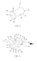
- Fig. 3 is a perspective view of an electric motor mounted in the motorcycle of Fig. 1;
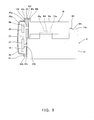
- Fig. 4 is a side view schematically showing a state in which the electric motor is mounted to a vehicle body of the motorcycle of Fig. 1;
- Fig. 5 is a rear view taken in the direction of an arrow V of Fig. 4.
- Fig. 1 is a left side view of a motorcycle 1 according to an embodiment of the present invention.
- the motorcycle 1 includes a front wheel 2 and a rear wheel 3.
- the front wheel 2 is rotatably mounted to a lower end portion of a front fork 4 extending substantially vertically.
- the front fork 4 is mounted on a steering shaft (not shown) by an upper bracket (not shown) attached to an upper end portion thereof, and an under bracket located below the upper bracket.
- the steering shaft is rotatably supported by a head pipe 5 externally attached to the steering shaft.
- a bar-type steering handle 6 extending rightward and leftward is attached to the upper bracket. When the rider rotates the steering handle 6 clockwise or counterclockwise, the front wheel 2 is turned to a desired direction with the steering shaft.
- a fuel tank 7 is disposed behind the steering handle 4.
- a straddle-type seat 8 is disposed behind the fuel tank 7.
- a pair of right and left main frame members 9 (only left main frame member 9 is illustrated in Fig. 1) forming a frame of a vehicle body extend to be tilted slightly downward and rearward from the head pipe 5.
- a pair of right and left pivot frame members (left pivot frame member is illustrated in Fig. 1) 10 are coupled to rear portions of the main frame members 9.
- a swing arm 11 extending substantially forward and rearward is pivotally mounted at a front end portion thereof to each pivot frame member 10.
- the rear wheel 3 which is a drive wheel is rotatably mounted to a rear end portion of the swing arm 11.
- An engine E is mounted on the right and left main frame members 9 and the pivot frame members 10 in such a manner that the engine E is disposed below the main frame members 9 and forward of the pivot frame members 10.
- a cowling 17 extends from a front portion to side portions of the vehicle body to cover the engine E and other components.
- the engine E is an inline four-cylinder engine.
- the engine E includes a cylinder block 44 that extends substantially vertically and has four cylinder portions aligned rightward and leftward, and a crankcase 15 that extends substantially horizontally rearward from a lower portion of the cylinder block 44 and accommodates the crankshaft 16 therein.
- the cylinder block 44 which is tilted slightly forward, and the crankcase 15 form a substantially L-shape in a side view.
- the cylinder block 44 includes a cylinder block body 12 for slidably accommodating a piston 24 therein, a cylinder head 13 that is coupled to an upper portion of the cylinder block body 12, forms a combustion chamber with the cylinder block body 12, and accommodates a DOHC valve system, and a cylinder head cover 14 covering an upper portion of the cylinder head 13 from above.
- An electric motor M for propelling the motorcycle 1 is disposed in a space formed behind the cylinder block 12 and above the crankcase 15 in a location forward of a connecting point A where the swing arm 11 and the pivot frame member 10 are coupled to each other.
- a first sprocket 46 is mounted on a left end portion of an output shaft Mc of the electric motor M.
- a second sprocket 47 is mounted on a left end portion of the crankshaft 16.
- An inverted tooth chain referred to as a silent chain 33 is wound around the first sprocket 46 and the second sprocket 47 to transmit a rotational force from the electric motor M to the crankshaft 16.
- An intake port 18 opens in a rear portion of the cylinder head 13 of the engine E.
- a throttle device 19 is disposed inside the main frame members 9 and is coupled to the intake port 18.
- the electric motor M is positioned below a connecting point where the intake port 18 and the throttle device 19 are coupled to each other.
- An air cleaner box 20 is disposed below the fuel tank 7 and is coupled to an upstream portion of the throttle device 19 in an intake-air flow direction.
- the air cleaner box 20 takes in the air from outside by utilizing a wind blowing from forward (ram pressure).
- An exhaust port 21 opens forward and downward at a front portion of the cylinder head 13.
- An upstream end of an exhaust pipe 22 is coupled to the exhaust port 21.
- the exhaust pipe 22 is extended forward from the exhaust port 21 of the engine E and then downward, and is further extended rearward through a region below the crankcase 15 of the engine E to a muffler 23 located behind.
- a large second electric power supplying unit 34, an inverter 35, a motor controller 36, a small first electric power supplying unit 42, and a DC/DC converter 43 are mounted.
- Fig. 2 is a block diagram of the motorcycle 1.
- the crankcase 15 accommodates the crankshaft 16 coupled to connecting rods 25 of the pistons 24 of the engine E, and a first clutch gear 26 is mounted on the crankshaft 16.
- a second clutch gear 28 is rotatably externally fitted to a main shaft 27 and is enmeshed with the first clutch gear 26.
- a counter shaft 31 is coupled to the main shaft 27 via a gear train 30 so that the counter shaft 31 can change its rotational speed.
- the counter shaft 31 is coupled to the rear wheel 3 via the chain 32.
- a path extending from the crankshaft 16 to the rear wheel 3 via the main shaft 27, the countershaft 31, and other components is a power transmission system.
- Torque from the electric motor M is transmitted to the crankshaft 16 via the first sprocket 46, the silent chain 33, and the second sprocket 47.
- Electric power is supplied from the second electric power supplying unit (e.g., battery of 144 voltage) 34 to the electric motor M via the inverter 35.
- a motor controller 36 is coupled to the inverter 35. The motor controller 36 controls driving timing and the torque of the electric motor M.
- a crank angle sensor 37 configured to detect a rotational angle of the crankshaft 16, a throttle valve opening degree sensor 38 configured to detect an opening degree of a throttle valve (not shown) disposed within the throttle device 19 (Fig. 1), a vehicle speed sensor 39 configured to detect a traveling speed of the motorcycle 1, a gear position sensor 40 configured to detect a gear position of the gar train 30 in the crankcase 15, are communicatively coupled to the motor controller 36.
- Torque from a starter motor 41 of the engine E is transmitted to the crankshaft 16.
- the starter motor 41 is configured to have a power output that is smaller than a power output of the electric motor M.
- the starter motor 41 is configured to be driven upon the rider turning on a starter switch (not shown) at the start of the engine E.
- the starter motor 41 is supplied with electric power from the first electric power supplying unit 42 (e.g., battery of 14 voltage) for supplying the electric power to an electric system of the motorcycle.
- the first electric power supplying unit 42 is coupled to the second electric power supplying unit 34 through a DC/DC converter 43.
- the generated electric power can be supplied to the second electric power supplying unit 34 and the electric power accumulated in the second electric power supplying unit 34 is decreased in voltage in the DC/DC converter 43 and is supplied to the first electric power supplying unit 42.
- Fig. 3 is a perspective view of the electric motor M mounted in the motorcycle 1.
- the electric motor M includes a cylindrical motor body Ma and a flange portion Mb provided at a left end portion of the motor body Ma.
- Bolt holes Md and Me are formed at desired locations on a periphery of the flange portion Mb.
- An output shaft Mc protrudes leftward from a center of the flange portion Mb.
- Plate-shaped mounting portions Mf and Mg having bolt holes protrude forward and backward from a peripheral surface of the motor body Ma.
- a plate-shaped mounting portion Mh having a bolt hole protrudes rightward from a right end surface of the motor body Ma.
- Fig. 4 is a side view schematically showing a state in which the electric motor M is mounted to the vehicle body of the motorcycle 1.
- Fig. 5 is a rear view taken in the direction of an arrow V of Fig. 4.
- a cover 48 shown in Fig. 5 is omitted.
- the electric motor M is disposed in a space formed behind the cylinder block body 12 and above the crankcase 15.
- a bracket 45 which is a metal plate is mounted to a left side surface of the crankcase 15 of the engine E so as to protrude to a left end surface of the electric motor M.
- Bolt holes 45a to 45f are formed on the bracket 45 in locations corresponding to the left side surface of the crankcase 15 of the engine E and in locations corresponding to the bolt holes Md and Me of the electric motor M.
- a penetrating hole 45g into which the output shaft Mc of the electric motor M is inserted and a penetrating hole 45h into which the crankshaft 16 is inserted are formed on the bracket 45.
- the first sprocket 46 mounted on a left end portion of the output shaft Mc and the second sprocket 47 mounted on the left end portion of the crankshaft 16 are disposed on the left side of the bracket 45.
- the cover 48 in which the first sprocket 46, the second sprocket 47 and the silent chain 33 wound around the first sprocket 46 and the second sprocket 47 are accommodated is mounted on the left side surface of the bracket 45.
- the cover 48 includes an accommodating portion 48a having a concave cross-section, and flange portions 48b and 48c that protrude in flange shape from a peripheral edge of the accommodating portion 48a and having bolt holes (not shown).
- bolts B1 are inserted into the bolt hole (not shown) of the flange portion 48b of the cover 48, the bolt holes 45a to 45d of the bracket 45, and the bolt holes (not shown) of the left side surface of the crankcase 15 of the engine E to fasten the cover 48, the bracket 45, and the engine E to each other.
- Bolts B2 are inserted into the bolt hole (not shown) of the flange portion 48c of the cover 48, the bolt holes 45e and 45f of he bracket 45, and the bolt holes Md and Me (Fig. 3) of the flange portion Mb of the electric motor M to fasten the cover 48, the bracket 45, and the electric motor M to each other.
- the rear mounting portion Mf of the electric motor M is placed on an upper surface 15a of a rear portion of the crankcase 15 of the engine E and is fastened to the upper surface 15a by a bolt B3.
- the front mounting portion Mg of the electric motor M is placed on an upper surface 12a formed on a back surface of the cylinder block body 12 of the engine E and is fastened to the upper surface 12a by a bolt B4.
- the right mounting portion Mh of the electric motor M is placed on an upper surface 15b of a right portion of the crankcase 15 of the engine E and is fastened to the upper surface 15b by a bolt B5.
- the exhaust pipe 22, elevated in temperature because of exhaust gas emitted from the engine E and flowing therein is extended from the cylinder block 12 forward relative to the engine E, whereas the electric motor M is disposed behind the cylinder block 12 of the engine E on the opposite side of the exhaust pipe 22. So, the electric motor M is less susceptible to heat radiation from the exhaust pipe 22.
- the exhaust pipe 22 extends through a region below the crankcase 15, whereas the electric motor M is disposed above the crankcase 15. So, the electric motor M is less susceptible to heat radiation from the exhaust pipe 22.
- the electric motor M is not substantially affected by disturbances such as heat. As a result, stable operation of the electric motor M can be achieved.
- the electric motor M is disposed in the space formed behind the cylinder block 12 and above the crankcase 15 in the engine E in which the cylinder block 12 and the crankcase 15 form the substantially L-shape in the side view, space efficiency improves, and increase in the size of the vehicle body can be suppressed.
- the electric motor M is disposed forward relative to the connecting point A where the front portion of the swing arm 11 is coupled to the pivot frame member 10, and behind the cylinder block 12 of the engine E so that the heavy weight of the electric motor M is mounted at a location near the center of gravity of the motorcycle 1. As a result, stability of the motorcycle 1 is improved.
- the first electric power supplying unit 42 for supplying the electric power to the starter motor 41 is charged with the electric power from the second electric power supplying unit 34 for supplying the electric power to the electric motor M.
- increase in the size of the vehicle body can be further suppressed.
- the silent chain 33 operates stably as compared to the construction in which the electric motor M is fixedly mounted to the vehicle body frame side.
- bracket 45 for mounting the electric motor M is mounted between the electric motor M and the engine E separately from the electric motor M and the engine E, it may alternatively be integral with an outer wall of the engine E.
- the electric motor M may be mounted to the vehicle frame side instead of the engine E side.
- capacitors or the like for accumulating electricity as electric charges may be used as the first electric power supplying unit 41 and the second electric power supplying unit 34 in this embodiment. Any other electric power accumulating devices may be used so long as they can accumulate and supply the electric power.
- the DC/DC converter 43 is disposed between the first electric power supplying unit 42 and the second electric power supplying unit 34 in this embodiment, it may be omitted if the first electric power supplying unit 42 can be charged with the electric power from the second electric power supplying unit 34 without a need for the DC/DC converter.
- the number of cylinders equipped in the motorcycle of the present invention is not intended to be limited.
Landscapes
- Engineering & Computer Science (AREA)
- Chemical & Material Sciences (AREA)
- Combustion & Propulsion (AREA)
- Transportation (AREA)
- Mechanical Engineering (AREA)
- Electric Propulsion And Braking For Vehicles (AREA)
- Automatic Cycles, And Cycles In General (AREA)
- Hybrid Electric Vehicles (AREA)
- Exhaust Silencers (AREA)
Abstract
Description
- The present invention relates a hybrid motorcycle that is equipped with an engine mounted between a front wheel and a rear wheel and an electric motor configured to propel the motorcycle, and includes an exhaust pipe that is coupled to the engine and is extended forward relative to the engine.
- In recent years, hybrid motor vehicles configured to travel by using a driving force generated by an electric motor in addition to an engine power have been developed (see
Japanese Laid-Open Patent Application Publication No. 6 - 64451 - When the electric motor is incorporated into a motorcycle, it is desirable to dispose the electric motor in a location where the electric motor is less susceptible to disturbances in the environment for the purpose of stable operation, because the electric motor operates on electric power. Furthermore, it is necessary to mount the electric motor efficiently in a limited space of the motorcycle so as not to increase the size of a vehicle body of the motorcycle.
- The present invention addresses the above described conditions, and an object of the present invention is to provide a hybrid motorcycle configured to be driven by an engine and an electric motor suitably disposed therein.
- According to the present invention, there is provided a motorcycle in which an engine is disposed between a front wheel and a rear wheel and an exhaust pipe for guiding an exhaust gas emitted from the engine is extended forward relative to the engine, the motorcycle comprising an electric motor that is disposed behind a cylinder portion of the engine and is configured to apply torque to a power transmission system including a crankshaft of the engine.
- In such a construction, the exhaust pipe, elevated in temperature because of high-temperature exhaust gas emitted from the engine and flowing therein, is extended forward relative to the engine, whereas the electric motor is disposed behind the cylinder portion of the engine on the opposite side of the exhaust pipe. Therefore, the electric motor is less susceptible to heat radiation from the exhaust pipe. As a result, the electric motor can operate stably.
- The engine may include a cylinder block forming the cylinder portion and a crankcase disposed at a lower portion of the cylinder block. The exhaust pipe may be extended rearward from a region forward of the cylinder block through a region below the crankcase. The electric motor may be disposed in a space formed behind the cylinder block and above the crankcase.
- In such a construction, since the electric motor is disposed in the space behind the cylinder block and above the crankcase, the size of the vehicle body is not substantially increased. In addition, since the exhaust pipe elevated in temperature is extended through the region below the crankcase whereas the electric motor is disposed above the crankcase, the electric motor is less susceptible to heat radiation from the exhaust pipe. As a result, the electric motor can operate more stably.
- The electric motor and the crankshaft may be coupled to each other laterally of the crankcase via a chain and sprocket mechanism.
- A frame member may be extended rearward from a head pipe for supporting the front wheel, a swing arm extending substantially forward and rearward may be pivoted at a front portion thereof to the frame member, and the rear wheel is rotatably mounted to a rear portion of the swing arm. The electric motor may be disposed forward relative to the connecting point where the swing arm and the frame member are coupled to each other.
- In such a construction, since the electric motor is disposed between the connecting point where the front portion of the swing arm is coupled to the frame member and the cylinder portion of the engine so that the heavy weight of the electric motor is positioned near the center of gravity of the motorcycle. Therefore, weight of the motorcycle is well-balanced.
- The motorcycle may further comprise a starter motor configured to apply a torque to the crankshaft to start the engine, a first electric power supplying unit configured to supply an electric power to the starter motor, and a second electric power supplying unit configured to supply the electric power to the electric motor and to have a voltage higher than a voltage of the first electric power supplying unit. The first electric power supplying unit may be configured to be able to be charged with the electric power supplied from the second electric power supplying unit.
- In such a construction, since the first electric power supplying unit configured to supply the electric power to the starter motor is charged with the electric power supplied from the second electric power supplying unit configured to supply the electric power to the electric motor, there is no need for an electric generator for charging the first electric power supplying unit.
As a result, the size of the vehicle body is not substantially increased. - The above and further objects and features of the invention will more fully be apparent from the following detailed description with accompanying drawings.
- Fig. 1 is a left side view of a motorcycle according to an embodiment of the present invention;
- Fig. 2 is a block diagram of a power transmission system of the motorcycle of Fig. 1;
- Fig. 3 is a perspective view of an electric motor mounted in the motorcycle of Fig. 1;
- Fig. 4 is a side view schematically showing a state in which the electric motor is mounted to a vehicle body of the motorcycle of Fig. 1; and
- Fig. 5 is a rear view taken in the direction of an arrow V of Fig. 4.
- Hereinafter, an embodiment of a motorcycle according to the present invention will be described with reference to the drawings. In this embodiment described below, the directions are referenced from the perspective of a rider (not shown) mounting the motorcycle.
- Fig. 1 is a left side view of a motorcycle 1 according to an embodiment of the present invention. As shown in Fig. 1, the motorcycle 1 includes a
front wheel 2 and arear wheel 3. Thefront wheel 2 is rotatably mounted to a lower end portion of afront fork 4 extending substantially vertically. Thefront fork 4 is mounted on a steering shaft (not shown) by an upper bracket (not shown) attached to an upper end portion thereof, and an under bracket located below the upper bracket. The steering shaft is rotatably supported by ahead pipe 5 externally attached to the steering shaft. A bar-type steering handle 6 extending rightward and leftward is attached to the upper bracket. When the rider rotates thesteering handle 6 clockwise or counterclockwise, thefront wheel 2 is turned to a desired direction with the steering shaft. Afuel tank 7 is disposed behind thesteering handle 4. A straddle-type seat 8 is disposed behind thefuel tank 7. - A pair of right and left main frame members 9 (only left
main frame member 9 is illustrated in Fig. 1) forming a frame of a vehicle body extend to be tilted slightly downward and rearward from thehead pipe 5. A pair of right and left pivot frame members (left pivot frame member is illustrated in Fig. 1) 10 are coupled to rear portions of themain frame members 9. Aswing arm 11 extending substantially forward and rearward is pivotally mounted at a front end portion thereof to each pivot frame member 10. Therear wheel 3 which is a drive wheel is rotatably mounted to a rear end portion of theswing arm 11. An engine E is mounted on the right and leftmain frame members 9 and the pivot frame members 10 in such a manner that the engine E is disposed below themain frame members 9 and forward of the pivot frame members 10. Acowling 17 extends from a front portion to side portions of the vehicle body to cover the engine E and other components. - The engine E is an inline four-cylinder engine. The engine E includes a
cylinder block 44 that extends substantially vertically and has four cylinder portions aligned rightward and leftward, and acrankcase 15 that extends substantially horizontally rearward from a lower portion of thecylinder block 44 and accommodates thecrankshaft 16 therein. In the engine E, thecylinder block 44, which is tilted slightly forward, and thecrankcase 15 form a substantially L-shape in a side view. Thecylinder block 44 includes acylinder block body 12 for slidably accommodating apiston 24 therein, acylinder head 13 that is coupled to an upper portion of thecylinder block body 12, forms a combustion chamber with thecylinder block body 12, and accommodates a DOHC valve system, and acylinder head cover 14 covering an upper portion of thecylinder head 13 from above. - An electric motor M for propelling the motorcycle 1 is disposed in a space formed behind the
cylinder block 12 and above thecrankcase 15 in a location forward of a connecting point A where theswing arm 11 and the pivot frame member 10 are coupled to each other. Afirst sprocket 46 is mounted on a left end portion of an output shaft Mc of the electric motor M. Asecond sprocket 47 is mounted on a left end portion of thecrankshaft 16. An inverted tooth chain referred to as asilent chain 33 is wound around thefirst sprocket 46 and thesecond sprocket 47 to transmit a rotational force from the electric motor M to thecrankshaft 16. - An
intake port 18 opens in a rear portion of thecylinder head 13 of the engine E.A throttle device 19 is disposed inside themain frame members 9 and is coupled to theintake port 18. The electric motor M is positioned below a connecting point where theintake port 18 and thethrottle device 19 are coupled to each other. Anair cleaner box 20 is disposed below thefuel tank 7 and is coupled to an upstream portion of thethrottle device 19 in an intake-air flow direction. Theair cleaner box 20 takes in the air from outside by utilizing a wind blowing from forward (ram pressure). Anexhaust port 21 opens forward and downward at a front portion of thecylinder head 13. An upstream end of anexhaust pipe 22 is coupled to theexhaust port 21. Theexhaust pipe 22 is extended forward from theexhaust port 21 of the engine E and then downward, and is further extended rearward through a region below thecrankcase 15 of the engine E to amuffler 23 located behind. At desired locations below theseat 8, a large second electricpower supplying unit 34, aninverter 35, amotor controller 36, a small first electricpower supplying unit 42, and a DC/DC converter 43 are mounted. - Fig. 2 is a block diagram of the motorcycle 1. As shown in Fig. 2, the
crankcase 15 accommodates thecrankshaft 16 coupled to connectingrods 25 of thepistons 24 of the engine E, and a first clutch gear 26 is mounted on thecrankshaft 16. A secondclutch gear 28 is rotatably externally fitted to amain shaft 27 and is enmeshed with the first clutch gear 26. In a state where a main clutch 29 fixedly mounted on an end portion of themain shaft 27 is engaged with the secondclutch gear 28, themain shaft 27 is rotatable in association with thecrankshaft 16. Acounter shaft 31 is coupled to themain shaft 27 via agear train 30 so that thecounter shaft 31 can change its rotational speed. Thecounter shaft 31 is coupled to therear wheel 3 via thechain 32. A path extending from thecrankshaft 16 to therear wheel 3 via themain shaft 27, thecountershaft 31, and other components is a power transmission system. - Torque from the electric motor M is transmitted to the
crankshaft 16 via thefirst sprocket 46, thesilent chain 33, and thesecond sprocket 47. Electric power is supplied from the second electric power supplying unit (e.g., battery of 144 voltage) 34 to the electric motor M via theinverter 35. Amotor controller 36 is coupled to theinverter 35. Themotor controller 36 controls driving timing and the torque of the electric motor M. - A
crank angle sensor 37 configured to detect a rotational angle of thecrankshaft 16, a throttle valveopening degree sensor 38 configured to detect an opening degree of a throttle valve (not shown) disposed within the throttle device 19 (Fig. 1), avehicle speed sensor 39 configured to detect a traveling speed of the motorcycle 1, agear position sensor 40 configured to detect a gear position of thegar train 30 in thecrankcase 15, are communicatively coupled to themotor controller 36. - Torque from a
starter motor 41 of the engine E is transmitted to thecrankshaft 16. Thestarter motor 41 is configured to have a power output that is smaller than a power output of the electric motor M. Thestarter motor 41 is configured to be driven upon the rider turning on a starter switch (not shown) at the start of the engine E. Thestarter motor 41 is supplied with electric power from the first electric power supplying unit 42 (e.g., battery of 14 voltage) for supplying the electric power to an electric system of the motorcycle. The first electricpower supplying unit 42 is coupled to the second electricpower supplying unit 34 through a DC/DC converter 43. When the electric motor M is used as an electric generator, the generated electric power can be supplied to the second electricpower supplying unit 34 and the electric power accumulated in the second electricpower supplying unit 34 is decreased in voltage in the DC/DC converter 43 and is supplied to the first electricpower supplying unit 42. - Fig. 3 is a perspective view of the electric motor M mounted in the motorcycle 1. As shown in Fig. 3, the electric motor M includes a cylindrical motor body Ma and a flange portion Mb provided at a left end portion of the motor body Ma. Bolt holes Md and Me are formed at desired locations on a periphery of the flange portion Mb. An output shaft Mc protrudes leftward from a center of the flange portion Mb.
Plate-shaped mounting portions Mf and Mg having bolt holes protrude forward and backward from a peripheral surface of the motor body Ma. A plate-shaped mounting portion Mh having a bolt hole protrudes rightward from a right end surface of the motor body Ma. - Fig. 4 is a side view schematically showing a state in which the electric motor M is mounted to the vehicle body of the motorcycle 1. Fig. 5 is a rear view taken in the direction of an arrow V of Fig. 4. In Fig. 4, for easier understanding, a
cover 48 shown in Fig. 5 is omitted. As shown in Figs. 4 and 5, the electric motor M is disposed in a space formed behind thecylinder block body 12 and above thecrankcase 15. Abracket 45 which is a metal plate is mounted to a left side surface of thecrankcase 15 of the engine E so as to protrude to a left end surface of the electric motor M. Bolt holes 45a to 45f are formed on thebracket 45 in locations corresponding to the left side surface of thecrankcase 15 of the engine E and in locations corresponding to the bolt holes Md and Me of the electric motor M. - As shown in Fig. 5, a penetrating
hole 45g into which the output shaft Mc of the electric motor M is inserted and a penetratinghole 45h into which thecrankshaft 16 is inserted are formed on thebracket 45. Thefirst sprocket 46 mounted on a left end portion of the output shaft Mc and thesecond sprocket 47 mounted on the left end portion of thecrankshaft 16 are disposed on the left side of thebracket 45. Thecover 48 in which thefirst sprocket 46, thesecond sprocket 47 and thesilent chain 33 wound around thefirst sprocket 46 and thesecond sprocket 47 are accommodated is mounted on the left side surface of thebracket 45. Thecover 48 includes anaccommodating portion 48a having a concave cross-section, andflange portions accommodating portion 48a and having bolt holes (not shown). - As shown in Figs. 4 and 5, bolts B1 are inserted into the bolt hole (not shown) of the
flange portion 48b of thecover 48, the bolt holes 45a to 45d of thebracket 45, and the bolt holes (not shown) of the left side surface of thecrankcase 15 of the engine E to fasten thecover 48, thebracket 45, and the engine E to each other. Bolts B2 are inserted into the bolt hole (not shown) of theflange portion 48c of thecover 48, the bolt holes 45e and 45f of hebracket 45, and the bolt holes Md and Me (Fig. 3) of the flange portion Mb of the electric motor M to fasten thecover 48, thebracket 45, and the electric motor M to each other. - As shown in Fig. 4, the rear mounting portion Mf of the electric motor M is placed on an
upper surface 15a of a rear portion of thecrankcase 15 of the engine E and is fastened to theupper surface 15a by a bolt B3. The front mounting portion Mg of the electric motor M is placed on anupper surface 12a formed on a back surface of thecylinder block body 12 of the engine E and is fastened to theupper surface 12a by a bolt B4. As shown in Fig. 5, the right mounting portion Mh of the electric motor M is placed on anupper surface 15b of a right portion of thecrankcase 15 of the engine E and is fastened to theupper surface 15b by a bolt B5. - In the above construction, as shown in Fig. 1, the
exhaust pipe 22, elevated in temperature because of exhaust gas emitted from the engine E and flowing therein is extended from thecylinder block 12 forward relative to the engine E, whereas the electric motor M is disposed behind thecylinder block 12 of the engine E on the opposite side of theexhaust pipe 22. So, the electric motor M is less susceptible to heat radiation from theexhaust pipe 22. In addition, theexhaust pipe 22 extends through a region below thecrankcase 15, whereas the electric motor M is disposed above thecrankcase 15. So, the electric motor M is less susceptible to heat radiation from theexhaust pipe 22. Thus, the electric motor M is not substantially affected by disturbances such as heat. As a result, stable operation of the electric motor M can be achieved. - Furthermore, since the electric motor M is disposed in the space formed behind the
cylinder block 12 and above thecrankcase 15 in the engine E in which thecylinder block 12 and thecrankcase 15 form the substantially L-shape in the side view, space efficiency improves, and increase in the size of the vehicle body can be suppressed. - The electric motor M is disposed forward relative to the connecting point A where the front portion of the
swing arm 11 is coupled to the pivot frame member 10, and behind thecylinder block 12 of the engine E so that the heavy weight of the electric motor M is mounted at a location near the center of gravity of the motorcycle 1. As a result, stability of the motorcycle 1 is improved. - As shown in Fig. 2, the first electric
power supplying unit 42 for supplying the electric power to thestarter motor 41 is charged with the electric power from the second electricpower supplying unit 34 for supplying the electric power to the electric motor M. This eliminates a need for an electric generator for charging the first electricpower supplying unit 42. As a result, increase in the size of the vehicle body can be further suppressed. - As shown in Figs. 4 and 5, since the electric motor M is fixedly mounted to the engine E side, a distance between the output shaft Mc of the electric motor M and the
crankshaft 16 is constant regardless of occurrence of great vibration through the vehicle body. As a result, thesilent chain 33 operates stably as compared to the construction in which the electric motor M is fixedly mounted to the vehicle body frame side. - Whereas the
bracket 45 for mounting the electric motor M is mounted between the electric motor M and the engine E separately from the electric motor M and the engine E, it may alternatively be integral with an outer wall of the engine E. In further alternative, the electric motor M may be mounted to the vehicle frame side instead of the engine E side. Whereas batteries for converting electric energy to chemical energy through a chemical reaction and accumulating the chemical energy therein are used as the first electricpower supplying unit 41 and the second electricpower supplying unit 34 in this embodiment, capacitors or the like for accumulating electricity as electric charges may be used. Any other electric power accumulating devices may be used so long as they can accumulate and supply the electric power. Whereas the DC/DC converter 43 is disposed between the first electricpower supplying unit 42 and the second electricpower supplying unit 34 in this embodiment, it may be omitted if the first electricpower supplying unit 42 can be charged with the electric power from the second electricpower supplying unit 34 without a need for the DC/DC converter. Moreover, the number of cylinders equipped in the motorcycle of the present invention is not intended to be limited. - As this invention may be embodied in several forms without departing from the spirit of essential characteristics thereof, the present embodiments are therefore illustrative and not restrictive, since the scope of the invention is defined by the appended claims rather than by the description preceding them, and all changes that fall within metes and bounds of the claims, or equivalence of such metes and bounds thereof are therefore intended to be embraced by the claims.
Claims (5)
- A motorcycle in which an engine is disposed between a front wheel and a rear wheel and an exhaust pipe for guiding an exhaust gas emitted from the engine is extended forward relative to the engine, the motorcycle comprising:an electric motor that is disposed behind a cylinder portion of the engine and is configured to apply a torque to a power transmission system including a crankshaft of the engine.
- The motorcycle according to claim 1,
wherein the engine includes a cylinder block forming the cylinder portion and a crankcase disposed at a lower portion of the cylinder block;
wherein the exhaust pipe is extended rearward from a region forward of the cylinder block through a region below the crankcase; and
wherein the electric motor is disposed in a space formed behind the cylinder block and above the crankcase. - The motorcycle according to claim 2,
wherein the electric motor and the crankshaft are coupled to each other laterally of the crankcase via a chain and sprocket mechanism. - The motorcycle according to any preceding claim,
wherein a frame member is extended rearward from a head pipe for supporting the front wheel, a swing arm extending substantially forward and rearward is pivoted at a front portion thereof to the frame member, and the rear wheel is rotatably mounted to a rear portion of the swing arm; and
wherein the electric motor is disposed forward relative to a connecting point where the swing arm and the frame member are coupled to each other. - The motorcycle according to any preceding claim, further comprising:a starter motor configured to apply a torque to the crankshaft to start the engine;a first electric power supplying unit configured to supply an electric power to the starter motor; anda second electric power supplying unit configured to supply the electric power to the electric motor and to have a voltage higher than a voltage of the first electric power supplying unit;wherein the first electric power supplying unit is configured to be able to be charged with the electric power supplied from the second electric power supplying unit.
Applications Claiming Priority (1)
| Application Number | Priority Date | Filing Date | Title |
|---|---|---|---|
| JP2006099542A JP4884818B2 (en) | 2006-03-31 | 2006-03-31 | Motorcycle |
Publications (3)
| Publication Number | Publication Date |
|---|---|
| EP1839925A2 true EP1839925A2 (en) | 2007-10-03 |
| EP1839925A3 EP1839925A3 (en) | 2011-07-20 |
| EP1839925B1 EP1839925B1 (en) | 2016-08-17 |
Family
ID=38262885
Family Applications (1)
| Application Number | Title | Priority Date | Filing Date |
|---|---|---|---|
| EP07006175.9A Not-in-force EP1839925B1 (en) | 2006-03-31 | 2007-03-26 | Motorcycle |
Country Status (3)
| Country | Link |
|---|---|
| US (1) | US7819211B2 (en) |
| EP (1) | EP1839925B1 (en) |
| JP (1) | JP4884818B2 (en) |
Cited By (6)
| Publication number | Priority date | Publication date | Assignee | Title |
|---|---|---|---|---|
| EP2236339A1 (en) | 2009-03-31 | 2010-10-06 | Honda Motor Co., Ltd. | Hybrid vehicle |
| KR101152549B1 (en) | 2009-03-31 | 2012-06-04 | 혼다 기켄 고교 가부시키가이샤 | Vehicle |
| EP2556977A1 (en) * | 2010-03-31 | 2013-02-13 | Honda Motor Co., Ltd. | Hybrid vehicle |
| EP3505437A1 (en) * | 2017-12-28 | 2019-07-03 | Kawasaki Jukogyo Kabushiki Kaisha | Hybrid straddle vehicle |
| DE102018106851A1 (en) | 2018-03-22 | 2019-09-26 | Schaeffler Technologies AG & Co. KG | Powertrain for a motorcycle |
| EP4151482A4 (en) * | 2020-05-12 | 2024-02-28 | Kawasaki Motors Ltd | Hybrid vehicle |
Families Citing this family (19)
| Publication number | Priority date | Publication date | Assignee | Title |
|---|---|---|---|---|
| JP5312110B2 (en) * | 2009-03-12 | 2013-10-09 | 本田技研工業株式会社 | Power unit for vehicle |
| JP5210210B2 (en) * | 2009-03-12 | 2013-06-12 | 本田技研工業株式会社 | Power unit for vehicle |
| JP5608032B2 (en) * | 2010-09-30 | 2014-10-15 | 本田技研工業株式会社 | Vehicle approach notification device for electric motorcycles |
| US8973690B2 (en) | 2010-10-04 | 2015-03-10 | W. Morrision Consulting Group, Inc. | Front wheel energy recovery system |
| US8950539B2 (en) | 2012-01-03 | 2015-02-10 | Hero Motorcorp Ltd. | Lightweight integrated rear suspension and drive enclosure for a ridden motorized vehicle |
| US20130168171A1 (en) * | 2012-01-03 | 2013-07-04 | Erik Buell | Ridden vehicle with hybrid power system |
| US9321358B2 (en) | 2012-07-06 | 2016-04-26 | Xtreme Products, Inc. | Light vehicles with on-board rapid charging systems and associated methods |
| JP5998037B2 (en) * | 2012-12-17 | 2016-09-28 | スズキ株式会社 | Power mechanism for hybrid vehicles |
| WO2014102851A1 (en) * | 2012-12-25 | 2014-07-03 | 川崎重工業株式会社 | Electric vehicle |
| JP6232915B2 (en) * | 2013-10-16 | 2017-11-22 | スズキ株式会社 | Hybrid motorcycle |
| US9302575B2 (en) * | 2014-03-13 | 2016-04-05 | GM Global Technology Operations LLC | Powertrain for a vehicle and a method of assembling the powertrain |
| EP2921398B1 (en) * | 2014-03-20 | 2017-02-22 | Askoll Eva S.R.L. | Electric propulsion unit and torque transmission group for an electric scooter and corresponding scooter |
| JP6894734B2 (en) | 2017-03-22 | 2021-06-30 | 川崎重工業株式会社 | Hybrid vehicle |
| JPWO2018173670A1 (en) | 2017-03-22 | 2019-11-14 | 川崎重工業株式会社 | Hybrid vehicle |
| JP2020152120A (en) * | 2017-07-18 | 2020-09-24 | ヤマハ発動機株式会社 | Vehicle |
| JP6908575B2 (en) * | 2018-12-25 | 2021-07-28 | 本田技研工業株式会社 | Saddle-type vehicle |
| JP7382163B2 (en) | 2019-07-02 | 2023-11-16 | カワサキモータース株式会社 | hybrid vehicle |
| JP7382162B2 (en) | 2019-07-02 | 2023-11-16 | カワサキモータース株式会社 | hybrid vehicle |
| JP7344024B2 (en) | 2019-07-02 | 2023-09-13 | カワサキモータース株式会社 | hybrid vehicle |
Citations (1)
| Publication number | Priority date | Publication date | Assignee | Title |
|---|---|---|---|---|
| JPH0664451A (en) | 1992-05-05 | 1994-03-08 | Franz Laimboeck | Driving device for automobile |
Family Cites Families (17)
| Publication number | Priority date | Publication date | Assignee | Title |
|---|---|---|---|---|
| JPS60246B2 (en) * | 1977-10-25 | 1985-01-07 | 本田技研工業株式会社 | Carburetor device for multi-cylinder engines in motorcycles |
| US4313080A (en) * | 1978-05-22 | 1982-01-26 | Battery Development Corporation | Method of charge control for vehicle hybrid drive batteries |
| AU539919B2 (en) * | 1980-09-22 | 1984-10-25 | Honda Giken Kogyo Kabushiki Kaisha | Motorcycle frame |
| US4492912A (en) * | 1983-01-12 | 1985-01-08 | General Motors Corporation | Dual voltage motor vehicle electrical system |
| JP2639532B2 (en) * | 1987-08-28 | 1997-08-13 | 東芝セラミックス株式会社 | How to cure castable refractories |
| JP3643133B2 (en) * | 1994-11-07 | 2005-04-27 | ヤマハ発動機株式会社 | Motorcycle |
| KR19990044295A (en) * | 1995-08-31 | 1999-06-25 | 호프만, 휘시텐부쉬 | Starters / generators for internal combustion engines, especially automotive internal combustion engines |
| US6155366A (en) * | 1998-10-13 | 2000-12-05 | Lin; Yu Tsai | Auxiliary electric driving system for vehicle |
| JP4391028B2 (en) * | 2001-02-20 | 2009-12-24 | 本田技研工業株式会社 | Control device for hybrid vehicle |
| JP2002307956A (en) * | 2001-04-11 | 2002-10-23 | Suzuki Motor Corp | Driving device for vehicle |
| JP4211243B2 (en) * | 2001-06-15 | 2009-01-21 | トヨタ自動車株式会社 | Charge control device |
| JP4411811B2 (en) * | 2001-08-24 | 2010-02-10 | トヨタ自動車株式会社 | Control device for hybrid vehicle |
| JP3567437B2 (en) * | 2002-03-28 | 2004-09-22 | 本田技研工業株式会社 | Power supply device for vehicle drive system |
| ITTO20021088A1 (en) * | 2002-12-16 | 2004-06-17 | Piaggio & C Spa | HYBRID MOTOR-DRIVER GROUP FOR A VEHICLE, PARTICULARLY FOR A SCOOTER. |
| JP4460331B2 (en) * | 2004-03-08 | 2010-05-12 | ヤマハ発動機株式会社 | Motorcycle |
| JP2005307755A (en) * | 2004-04-16 | 2005-11-04 | Fuji Heavy Ind Ltd | Starter |
| JP2006076496A (en) * | 2004-09-10 | 2006-03-23 | Yamaha Motor Co Ltd | Vehicle |
-
2006
- 2006-03-31 JP JP2006099542A patent/JP4884818B2/en not_active Expired - Fee Related
-
2007
- 2007-03-21 US US11/726,720 patent/US7819211B2/en not_active Expired - Fee Related
- 2007-03-26 EP EP07006175.9A patent/EP1839925B1/en not_active Not-in-force
Patent Citations (1)
| Publication number | Priority date | Publication date | Assignee | Title |
|---|---|---|---|---|
| JPH0664451A (en) | 1992-05-05 | 1994-03-08 | Franz Laimboeck | Driving device for automobile |
Cited By (15)
| Publication number | Priority date | Publication date | Assignee | Title |
|---|---|---|---|---|
| US8556021B2 (en) | 2009-03-31 | 2013-10-15 | Honda Motor Co., Ltd. | Hybrid vehicle |
| CN101890903A (en) * | 2009-03-31 | 2010-11-24 | 本田技研工业株式会社 | Hybrid vehicle |
| KR101152549B1 (en) | 2009-03-31 | 2012-06-04 | 혼다 기켄 고교 가부시키가이샤 | Vehicle |
| EP2236339A1 (en) | 2009-03-31 | 2010-10-06 | Honda Motor Co., Ltd. | Hybrid vehicle |
| US8424626B2 (en) | 2009-03-31 | 2013-04-23 | Honda Motor Co., Ltd. | Vehicle |
| CN101890903B (en) * | 2009-03-31 | 2013-12-11 | 本田技研工业株式会社 | Hybrid vehicle |
| EP2556977A1 (en) * | 2010-03-31 | 2013-02-13 | Honda Motor Co., Ltd. | Hybrid vehicle |
| EP2556977A4 (en) * | 2010-03-31 | 2013-08-07 | Honda Motor Co Ltd | Hybrid vehicle |
| TWI454406B (en) * | 2010-03-31 | 2014-10-01 | Honda Motor Co Ltd | Hybrid vehicle |
| US9352800B2 (en) | 2010-03-31 | 2016-05-31 | Honda Motor Co., Ltd. | Hybrid vehicle |
| EP3505437A1 (en) * | 2017-12-28 | 2019-07-03 | Kawasaki Jukogyo Kabushiki Kaisha | Hybrid straddle vehicle |
| CN110027652A (en) * | 2017-12-28 | 2019-07-19 | 川崎重工业株式会社 | The Straddle-type vehicle of hybrid power type |
| DE102018106851A1 (en) | 2018-03-22 | 2019-09-26 | Schaeffler Technologies AG & Co. KG | Powertrain for a motorcycle |
| DE102018106851B4 (en) | 2018-03-22 | 2022-01-13 | Schaeffler Technologies AG & Co. KG | Motorcycle with a power train |
| EP4151482A4 (en) * | 2020-05-12 | 2024-02-28 | Kawasaki Motors Ltd | Hybrid vehicle |
Also Published As
| Publication number | Publication date |
|---|---|
| US7819211B2 (en) | 2010-10-26 |
| US20070235235A1 (en) | 2007-10-11 |
| JP4884818B2 (en) | 2012-02-29 |
| JP2007269253A (en) | 2007-10-18 |
| EP1839925A3 (en) | 2011-07-20 |
| EP1839925B1 (en) | 2016-08-17 |
Similar Documents
| Publication | Publication Date | Title |
|---|---|---|
| EP1839925B1 (en) | Motorcycle | |
| US7527111B2 (en) | Driving device for hybrid vehicle, and hybrid vehicle incorporating the same | |
| JP4667090B2 (en) | Hybrid vehicle drive unit, hybrid vehicle and motorcycle | |
| EP1270302B1 (en) | Energy recovery mechanism in a scooter | |
| JP3649312B2 (en) | Driving force transmission device for hybrid vehicle | |
| US20060289214A1 (en) | Driving device for a hybrid vehicle, and a hybrid vehicle having the same | |
| JP4401286B2 (en) | Electric motorcycle harness structure | |
| US8348005B2 (en) | Hybrid vehicle | |
| US6119801A (en) | Power assisted bicycle | |
| JP3942773B2 (en) | Series hybrid electric motorcycle | |
| JP2001334985A (en) | Power unit of motorcycle | |
| JP3942772B2 (en) | Series hybrid electric motorcycle | |
| CN101947997B (en) | Hybrid power and saddle type vehicle | |
| JPWO2005063559A1 (en) | Electric vehicle | |
| JP4041468B2 (en) | Hybrid vehicle | |
| JP4042872B2 (en) | Driving device for motorcycle | |
| JP4039572B2 (en) | Hybrid electric vehicle | |
| JP2005186814A (en) | Electric vehicle | |
| JP2005231423A (en) | Hybrid vehicle | |
| JP3565209B2 (en) | Motorcycle with electric motor | |
| JP2005132284A (en) | Electromotive vehicle | |
| JP2005194930A (en) | Swing arm unit and electric vehicle | |
| JP2001105899A (en) | Series hybrid type electric two wheeler | |
| KR100911216B1 (en) | Hybrid power transmission apparatus with manual and automatic function | |
| JP3616602B2 (en) | Motorcycle drive device |
Legal Events
| Date | Code | Title | Description |
|---|---|---|---|
| PUAI | Public reference made under article 153(3) epc to a published international application that has entered the european phase |
Free format text: ORIGINAL CODE: 0009012 |
|
| 17P | Request for examination filed |
Effective date: 20070326 |
|
| AK | Designated contracting states |
Kind code of ref document: A2 Designated state(s): AT BE BG CH CY CZ DE DK EE ES FI FR GB GR HU IE IS IT LI LT LU LV MC MT NL PL PT RO SE SI SK TR |
|
| AX | Request for extension of the european patent |
Extension state: AL BA HR MK YU |
|
| PUAL | Search report despatched |
Free format text: ORIGINAL CODE: 0009013 |
|
| AK | Designated contracting states |
Kind code of ref document: A3 Designated state(s): AT BE BG CH CY CZ DE DK EE ES FI FR GB GR HU IE IS IT LI LT LU LV MC MT NL PL PT RO SE SI SK TR |
|
| AX | Request for extension of the european patent |
Extension state: AL BA HR MK RS |
|
| AKX | Designation fees paid |
Designated state(s): AT BE BG CH CY CZ DE DK EE ES FI FR GB GR HU IE IS IT LI LT LU LV MC MT NL PL PT RO SE SI SK TR |
|
| 17Q | First examination report despatched |
Effective date: 20141125 |
|
| GRAP | Despatch of communication of intention to grant a patent |
Free format text: ORIGINAL CODE: EPIDOSNIGR1 |
|
| INTG | Intention to grant announced |
Effective date: 20160527 |
|
| GRAS | Grant fee paid |
Free format text: ORIGINAL CODE: EPIDOSNIGR3 |
|
| GRAA | (expected) grant |
Free format text: ORIGINAL CODE: 0009210 |
|
| AK | Designated contracting states |
Kind code of ref document: B1 Designated state(s): AT BE BG CH CY CZ DE DK EE ES FI FR GB GR HU IE IS IT LI LT LU LV MC MT NL PL PT RO SE SI SK TR |
|
| REG | Reference to a national code |
Ref country code: GB Ref legal event code: FG4D |
|
| REG | Reference to a national code |
Ref country code: CH Ref legal event code: EP |
|
| REG | Reference to a national code |
Ref country code: IE Ref legal event code: FG4D |
|
| REG | Reference to a national code |
Ref country code: AT Ref legal event code: REF Ref document number: 820686 Country of ref document: AT Kind code of ref document: T Effective date: 20160915 |
|
| REG | Reference to a national code |
Ref country code: DE Ref legal event code: R096 Ref document number: 602007047457 Country of ref document: DE |
|
| REG | Reference to a national code |
Ref country code: NL Ref legal event code: MP Effective date: 20160817 |
|
| REG | Reference to a national code |
Ref country code: LT Ref legal event code: MG4D |
|
| REG | Reference to a national code |
Ref country code: AT Ref legal event code: MK05 Ref document number: 820686 Country of ref document: AT Kind code of ref document: T Effective date: 20160817 |
|
| PG25 | Lapsed in a contracting state [announced via postgrant information from national office to epo] |
Ref country code: LT Free format text: LAPSE BECAUSE OF FAILURE TO SUBMIT A TRANSLATION OF THE DESCRIPTION OR TO PAY THE FEE WITHIN THE PRESCRIBED TIME-LIMIT Effective date: 20160817 Ref country code: FI Free format text: LAPSE BECAUSE OF FAILURE TO SUBMIT A TRANSLATION OF THE DESCRIPTION OR TO PAY THE FEE WITHIN THE PRESCRIBED TIME-LIMIT Effective date: 20160817 Ref country code: NL Free format text: LAPSE BECAUSE OF FAILURE TO SUBMIT A TRANSLATION OF THE DESCRIPTION OR TO PAY THE FEE WITHIN THE PRESCRIBED TIME-LIMIT Effective date: 20160817 |
|
| PG25 | Lapsed in a contracting state [announced via postgrant information from national office to epo] |
Ref country code: LV Free format text: LAPSE BECAUSE OF FAILURE TO SUBMIT A TRANSLATION OF THE DESCRIPTION OR TO PAY THE FEE WITHIN THE PRESCRIBED TIME-LIMIT Effective date: 20160817 Ref country code: GR Free format text: LAPSE BECAUSE OF FAILURE TO SUBMIT A TRANSLATION OF THE DESCRIPTION OR TO PAY THE FEE WITHIN THE PRESCRIBED TIME-LIMIT Effective date: 20161118 Ref country code: PT Free format text: LAPSE BECAUSE OF FAILURE TO SUBMIT A TRANSLATION OF THE DESCRIPTION OR TO PAY THE FEE WITHIN THE PRESCRIBED TIME-LIMIT Effective date: 20161219 Ref country code: ES Free format text: LAPSE BECAUSE OF FAILURE TO SUBMIT A TRANSLATION OF THE DESCRIPTION OR TO PAY THE FEE WITHIN THE PRESCRIBED TIME-LIMIT Effective date: 20160817 Ref country code: SE Free format text: LAPSE BECAUSE OF FAILURE TO SUBMIT A TRANSLATION OF THE DESCRIPTION OR TO PAY THE FEE WITHIN THE PRESCRIBED TIME-LIMIT Effective date: 20160817 Ref country code: PL Free format text: LAPSE BECAUSE OF FAILURE TO SUBMIT A TRANSLATION OF THE DESCRIPTION OR TO PAY THE FEE WITHIN THE PRESCRIBED TIME-LIMIT Effective date: 20160817 Ref country code: AT Free format text: LAPSE BECAUSE OF FAILURE TO SUBMIT A TRANSLATION OF THE DESCRIPTION OR TO PAY THE FEE WITHIN THE PRESCRIBED TIME-LIMIT Effective date: 20160817 |
|
| PG25 | Lapsed in a contracting state [announced via postgrant information from national office to epo] |
Ref country code: EE Free format text: LAPSE BECAUSE OF FAILURE TO SUBMIT A TRANSLATION OF THE DESCRIPTION OR TO PAY THE FEE WITHIN THE PRESCRIBED TIME-LIMIT Effective date: 20160817 Ref country code: RO Free format text: LAPSE BECAUSE OF FAILURE TO SUBMIT A TRANSLATION OF THE DESCRIPTION OR TO PAY THE FEE WITHIN THE PRESCRIBED TIME-LIMIT Effective date: 20160817 |
|
| REG | Reference to a national code |
Ref country code: DE Ref legal event code: R097 Ref document number: 602007047457 Country of ref document: DE |
|
| PG25 | Lapsed in a contracting state [announced via postgrant information from national office to epo] |
Ref country code: BG Free format text: LAPSE BECAUSE OF FAILURE TO SUBMIT A TRANSLATION OF THE DESCRIPTION OR TO PAY THE FEE WITHIN THE PRESCRIBED TIME-LIMIT Effective date: 20161117 Ref country code: BE Free format text: LAPSE BECAUSE OF FAILURE TO SUBMIT A TRANSLATION OF THE DESCRIPTION OR TO PAY THE FEE WITHIN THE PRESCRIBED TIME-LIMIT Effective date: 20160817 Ref country code: CZ Free format text: LAPSE BECAUSE OF FAILURE TO SUBMIT A TRANSLATION OF THE DESCRIPTION OR TO PAY THE FEE WITHIN THE PRESCRIBED TIME-LIMIT Effective date: 20160817 Ref country code: DK Free format text: LAPSE BECAUSE OF FAILURE TO SUBMIT A TRANSLATION OF THE DESCRIPTION OR TO PAY THE FEE WITHIN THE PRESCRIBED TIME-LIMIT Effective date: 20160817 Ref country code: SK Free format text: LAPSE BECAUSE OF FAILURE TO SUBMIT A TRANSLATION OF THE DESCRIPTION OR TO PAY THE FEE WITHIN THE PRESCRIBED TIME-LIMIT Effective date: 20160817 |
|
| PLBE | No opposition filed within time limit |
Free format text: ORIGINAL CODE: 0009261 |
|
| STAA | Information on the status of an ep patent application or granted ep patent |
Free format text: STATUS: NO OPPOSITION FILED WITHIN TIME LIMIT |
|
| 26N | No opposition filed |
Effective date: 20170518 |
|
| PG25 | Lapsed in a contracting state [announced via postgrant information from national office to epo] |
Ref country code: SI Free format text: LAPSE BECAUSE OF FAILURE TO SUBMIT A TRANSLATION OF THE DESCRIPTION OR TO PAY THE FEE WITHIN THE PRESCRIBED TIME-LIMIT Effective date: 20160817 |
|
| REG | Reference to a national code |
Ref country code: CH Ref legal event code: PL |
|
| GBPC | Gb: european patent ceased through non-payment of renewal fee |
Effective date: 20170326 |
|
| PG25 | Lapsed in a contracting state [announced via postgrant information from national office to epo] |
Ref country code: MC Free format text: LAPSE BECAUSE OF FAILURE TO SUBMIT A TRANSLATION OF THE DESCRIPTION OR TO PAY THE FEE WITHIN THE PRESCRIBED TIME-LIMIT Effective date: 20160817 |
|
| REG | Reference to a national code |
Ref country code: IE Ref legal event code: MM4A |
|
| REG | Reference to a national code |
Ref country code: FR Ref legal event code: ST Effective date: 20171130 |
|
| PG25 | Lapsed in a contracting state [announced via postgrant information from national office to epo] |
Ref country code: LU Free format text: LAPSE BECAUSE OF NON-PAYMENT OF DUE FEES Effective date: 20170326 Ref country code: FR Free format text: LAPSE BECAUSE OF NON-PAYMENT OF DUE FEES Effective date: 20170331 |
|
| PG25 | Lapsed in a contracting state [announced via postgrant information from national office to epo] |
Ref country code: GB Free format text: LAPSE BECAUSE OF NON-PAYMENT OF DUE FEES Effective date: 20170326 Ref country code: LI Free format text: LAPSE BECAUSE OF NON-PAYMENT OF DUE FEES Effective date: 20170331 Ref country code: CH Free format text: LAPSE BECAUSE OF NON-PAYMENT OF DUE FEES Effective date: 20170331 Ref country code: IT Free format text: LAPSE BECAUSE OF NON-PAYMENT OF DUE FEES Effective date: 20170326 Ref country code: IE Free format text: LAPSE BECAUSE OF NON-PAYMENT OF DUE FEES Effective date: 20170326 |
|
| PGFP | Annual fee paid to national office [announced via postgrant information from national office to epo] |
Ref country code: DE Payment date: 20180313 Year of fee payment: 12 |
|
| PG25 | Lapsed in a contracting state [announced via postgrant information from national office to epo] |
Ref country code: MT Free format text: LAPSE BECAUSE OF NON-PAYMENT OF DUE FEES Effective date: 20170326 |
|
| RIC2 | Information provided on ipc code assigned after grant |
Ipc: B62K 11/04 20060101ALI20070827BHEP Ipc: B60K 6/22 20071001AFI20070827BHEP |
|
| PG25 | Lapsed in a contracting state [announced via postgrant information from national office to epo] |
Ref country code: HU Free format text: LAPSE BECAUSE OF FAILURE TO SUBMIT A TRANSLATION OF THE DESCRIPTION OR TO PAY THE FEE WITHIN THE PRESCRIBED TIME-LIMIT; INVALID AB INITIO Effective date: 20070326 |
|
| REG | Reference to a national code |
Ref country code: DE Ref legal event code: R119 Ref document number: 602007047457 Country of ref document: DE |
|
| PG25 | Lapsed in a contracting state [announced via postgrant information from national office to epo] |
Ref country code: CY Free format text: LAPSE BECAUSE OF NON-PAYMENT OF DUE FEES Effective date: 20160817 |
|
| PG25 | Lapsed in a contracting state [announced via postgrant information from national office to epo] |
Ref country code: DE Free format text: LAPSE BECAUSE OF NON-PAYMENT OF DUE FEES Effective date: 20191001 |
|
| PG25 | Lapsed in a contracting state [announced via postgrant information from national office to epo] |
Ref country code: TR Free format text: LAPSE BECAUSE OF FAILURE TO SUBMIT A TRANSLATION OF THE DESCRIPTION OR TO PAY THE FEE WITHIN THE PRESCRIBED TIME-LIMIT Effective date: 20160817 |
|
| PG25 | Lapsed in a contracting state [announced via postgrant information from national office to epo] |
Ref country code: IS Free format text: LAPSE BECAUSE OF FAILURE TO SUBMIT A TRANSLATION OF THE DESCRIPTION OR TO PAY THE FEE WITHIN THE PRESCRIBED TIME-LIMIT Effective date: 20161217 |