JP6232915B2 - Hybrid motorcycle - Google Patents

Hybrid motorcycle Download PDF

Info

Publication number
JP6232915B2
JP6232915B2 JP2013215782A JP2013215782A JP6232915B2 JP 6232915 B2 JP6232915 B2 JP 6232915B2 JP 2013215782 A JP2013215782 A JP 2013215782A JP 2013215782 A JP2013215782 A JP 2013215782A JP 6232915 B2 JP6232915 B2 JP 6232915B2
Authority
JP
Japan
Prior art keywords
motor
shift
engine
clutch
actuator
Prior art date
Legal status (The legal status is an assumption and is not a legal conclusion. Google has not performed a legal analysis and makes no representation as to the accuracy of the status listed.)
Active
Application number
JP2013215782A
Other languages
Japanese (ja)
Other versions
JP2015077887A (en
Inventor
田中 浩一
浩一 田中
Current Assignee (The listed assignees may be inaccurate. Google has not performed a legal analysis and makes no representation or warranty as to the accuracy of the list.)
Suzuki Motor Co Ltd
Original Assignee
Suzuki Motor Co Ltd
Priority date (The priority date is an assumption and is not a legal conclusion. Google has not performed a legal analysis and makes no representation as to the accuracy of the date listed.)
Filing date
Publication date
Application filed by Suzuki Motor Co Ltd filed Critical Suzuki Motor Co Ltd
Priority to JP2013215782A priority Critical patent/JP6232915B2/en
Publication of JP2015077887A publication Critical patent/JP2015077887A/en
Application granted granted Critical
Publication of JP6232915B2 publication Critical patent/JP6232915B2/en
Active legal-status Critical Current
Anticipated expiration legal-status Critical

Links

Images

Classifications

    • YGENERAL TAGGING OF NEW TECHNOLOGICAL DEVELOPMENTS; GENERAL TAGGING OF CROSS-SECTIONAL TECHNOLOGIES SPANNING OVER SEVERAL SECTIONS OF THE IPC; TECHNICAL SUBJECTS COVERED BY FORMER USPC CROSS-REFERENCE ART COLLECTIONS [XRACs] AND DIGESTS
    • Y02TECHNOLOGIES OR APPLICATIONS FOR MITIGATION OR ADAPTATION AGAINST CLIMATE CHANGE
    • Y02TCLIMATE CHANGE MITIGATION TECHNOLOGIES RELATED TO TRANSPORTATION
    • Y02T10/00Road transport of goods or passengers
    • Y02T10/60Other road transportation technologies with climate change mitigation effect
    • Y02T10/62Hybrid vehicles

Description

本発明は、エンジンを駆動源としたエンジン走行とモータを駆動源としたEV(Electric Vehicle)走行とを組み合せたハイブリッド二輪車に関する。   The present invention relates to a hybrid two-wheeled vehicle in which engine running using an engine as a drive source and EV (Electric Vehicle) running using a motor as a drive source are combined.

近年、自動二輪車は、環境問題が重視されており、エンジン駆動式の車両から排出される環境汚染物質の削減が求められる。そのため、自動二輪車においても、エンジン駆動とともに、車輪を駆動する駆動モータ(EV走行用モータ)を搭載して、駆動モータにより駆動輪(後輪)を駆動させるハイブリッド二輪車が開発されている。   2. Description of the Related Art In recent years, environmental issues have been emphasized in motorcycles, and it is required to reduce environmental pollutants discharged from engine-driven vehicles. Therefore, in motorcycles, a hybrid motorcycle has been developed in which a drive motor (EV traveling motor) that drives wheels is mounted together with the engine drive, and the drive wheels (rear wheels) are driven by the drive motor.

従来のハイブリッド二輪車として、駆動モータと発電機とをそれぞれ配置し、ユニットスイング型エンジンを搭載した特許文献1に記載の自動二輪車がある。この自動二輪車は、駆動モータが後輪駆動軸上に、車両中心線に対し車幅方向外側に、オフセットして配置される。駆動モータは、車幅方向最外側配置の減速機構と後車輪との間に配置され、発電機はシリンダアッセンブリの外側方で、かつ、駆動モータよりさらに車幅方向外側に配置される。   As a conventional hybrid motorcycle, there is a motorcycle described in Patent Document 1 in which a drive motor and a generator are arranged and a unit swing type engine is mounted. In this motorcycle, the drive motor is disposed on the rear wheel drive shaft, offset from the vehicle center line in the vehicle width direction. The drive motor is disposed between the speed reduction mechanism disposed at the outermost side in the vehicle width direction and the rear wheel, and the generator is disposed on the outer side of the cylinder assembly and further on the outer side in the vehicle width direction than the drive motor.

また、特許文献2に記載のハイブリッド二輪車は、駆動軸の延長上で車幅方向に、クラッチ機構、発電機、動力分配装置および駆動モータが順次それぞれ配置される。駆動モータはEV走行用モータを構成するもので、車両中心線から車幅方向外側の遠い位置に配置されている。   In the hybrid motorcycle described in Patent Document 2, a clutch mechanism, a generator, a power distribution device, and a drive motor are sequentially arranged in the vehicle width direction on the extension of the drive shaft. The drive motor constitutes an EV travel motor, and is disposed at a position far from the vehicle center line on the outer side in the vehicle width direction.

特開2005−247247号公報JP 2005-247247 A 特開2007−216812号公報JP 2007-216812 A

特許文献1に記載のハイブリッド二輪車では、駆動モータは後輪駆動軸上に車両中心線に対して車幅方向外側にオフセットして配置され、さらに、発電機はシリンダアッセンブリの外側方で駆動モータよりさらに車幅方向外側に配置されているために、車両幅方向に延びる駆動軸上に駆動モータの他に減速機構が設けられて複雑な配置構成となってエンジン幅や車両幅が拡大し、バンク角の不足が生じたり、車両の左右の重量バランスが悪化し、操縦安定性が著しく悪化する。   In the hybrid motorcycle described in Patent Document 1, the drive motor is disposed on the rear wheel drive shaft so as to be offset outward in the vehicle width direction with respect to the vehicle center line, and the generator is disposed on the outer side of the cylinder assembly from the drive motor. Furthermore, because it is arranged on the outer side in the vehicle width direction, a reduction mechanism is provided in addition to the drive motor on the drive shaft extending in the vehicle width direction, resulting in a complicated arrangement configuration, and the engine width and vehicle width are increased. Insufficient corners occur, the weight balance between the left and right sides of the vehicle deteriorates, and steering stability deteriorates significantly.

また、特許文献2に記載のハイブリッド二輪車では、エンジン駆動力とモータ駆動力を切り離して制御しており、駆動モータはドライブシャフト(カウンタシャフト)上に配置される。このためドライブシャフト軸の径が大きくなり、さらに、クランクシャフトとスイングアームピボットが車両前後方向に離れるために、車両軸間距離が延び、取り回しが困難になる。   Moreover, in the hybrid motorcycle described in Patent Document 2, the engine driving force and the motor driving force are controlled separately, and the driving motor is disposed on the drive shaft (counter shaft). For this reason, the diameter of the drive shaft is increased, and the crankshaft and the swing arm pivot are separated from each other in the vehicle front-rear direction, so that the distance between the vehicle axes is extended, and the handling becomes difficult.

本発明は、上述した事情を考慮してなされたものであり、エンジン幅を増大させずにオートマチックマニュアルトランスミッション装置(AMT)とEV走行用モータ(駆動モータ)を組み合せてコンパクトに配置でき、車両左右の重量バランスを保って操縦安定性を良好にしたハイブリッド二輪車を提供することを目的とする。   The present invention has been made in consideration of the above-mentioned circumstances, and can be arranged compactly by combining an automatic manual transmission device (AMT) and an EV driving motor (drive motor) without increasing the engine width. An object of the present invention is to provide a hybrid two-wheeled vehicle that maintains good weight balance and has good steering stability.

本発明の他の目的は、AMTとEV走行用モータ(駆動モータ)とを組み合せて配置しても、AMTアクチュエータとEV走行用モータ(駆動モータ)との配置の両立を車両幅方向に図ることができ、AMTの消費電力を賄うためのモータ発電、EV走行、エンジン始動およびエンジン走行を行なうことができるハイブリッド二輪車を提供するにある。   Another object of the present invention is to achieve coexistence of the arrangement of the AMT actuator and the EV driving motor (drive motor) in the vehicle width direction even when the AMT and the EV driving motor (drive motor) are combined. Therefore, it is an object of the present invention to provide a hybrid motorcycle that can perform motor power generation, EV traveling, engine starting, and engine traveling to cover the power consumption of AMT.

本発明に係るハイブリッド二輪車は、上述した課題を解決するために、シフトカムとシフトフォークとによって変速用ドッグを移動させるトランスミッション機構と、エンジン回転を前記トランスミッション機構に対して伝達および遮断するクラッチ機構と、前記クラッチ機構を断続維持させるクラッチアクチュエータと、前記トランスミッション機構を変速操作させるシフトチェンジアクチュエータと、シフトチェンジ制御を行なう制御ロジックを備えたトランスミッションコントロールユニット(TCU)と、からオートマチックマニュアルトランスミッション装置(AMT)を構成し、前記トランスミッション機構は、カウンタシャフトに設けられる複数のドライブギアと、ドライブシャフトに設けられ、前記複数のドライブギアのそれぞれに常時噛合する複数のドリブンギアとを備え、車両中心線上を跨って配置したEV走行用モータを備え、前記複数のドライブギアのうち前記カウンタシャフトに直結して回転する所定のドライブギアに、前記EV走行用モータの回転が伝達される減速機構を直接噛み合せ、モータ駆動力を前記トランスミッション機構に伝達するモータ駆動力伝達機構を備えることを特徴とするものである。 In order to solve the above-described problem, a hybrid motorcycle according to the present invention includes a transmission mechanism that moves a shift dog by a shift cam and a shift fork, a clutch mechanism that transmits and blocks engine rotation to and from the transmission mechanism, An automatic manual transmission device (AMT) comprising: a clutch actuator that maintains the clutch mechanism intermittently; a shift change actuator that shifts the transmission mechanism; and a transmission control unit (TCU) that includes a control logic that performs shift change control. configured, the transmission mechanism includes a plurality of drive gears provided on countershaft, provided on the drive shaft, its said plurality of drive gear And a plurality of driven gears which always meshes with, respectively, provided with an EV traveling motor disposed across the vehicle center line, a predetermined drive gear that rotates directly connected to the counter shaft of the plurality of drive gear , meshing reduction mechanism the rotation of the EV traction motor is directly transmitted, is characterized in that a motor driving force transmission mechanism for transmitting motor driving force to the transmission mechanism.

本発明においては、オートマチックマニュアルトランスミッション装置(AMT)とEV走行用モータ(駆動モータ)とを組み合せてコンパクトに配置でき、車両左右の重量バランスを保って操縦安定性を良好にしたハイブリッド二輪車を提供できる。   In the present invention, it is possible to provide a hybrid two-wheeled vehicle that can be compactly arranged by combining an automatic manual transmission device (AMT) and an EV traveling motor (driving motor), and that maintains a weight balance between the left and right sides of the vehicle and has good steering stability. .

このハイブリッド二輪車は、AMTと駆動モータとを組み合せて配置しても、AMTアクチュエータと駆動モータとの配置の両立を車両幅方向に図ることができ、AMTの消費電力を賄うモータ発電、EV走行、エンジン始動およびエンジン走行をトランスミッションコントロールユニットの制御により行なうことができる。   Even if this hybrid motorcycle is arranged in combination with an AMT and a drive motor, the arrangement of the AMT actuator and the drive motor can be achieved in the vehicle width direction, and motor power generation, EV running, Engine starting and engine running can be performed under the control of the transmission control unit.

本発明の実施形態におけるハイブリッド二輪車の全体を示す左側面図。The left view which shows the whole hybrid two-wheeled vehicle in embodiment of this invention. 前記ハイブリッド二輪車の全体を一部省略して示す平面図。The top view which abbreviate | omits and shows a part of the said whole hybrid motorcycle. 前記ハイブリッド二輪車の操向ハンドルを後上方から見た斜視図。The perspective view which looked at the steering handle of the said hybrid motorcycle from back upper direction. 前記ハイブリッド二輪車の車体フレームに搭載されるエンジンユニットを示す左側面図。The left view which shows the engine unit mounted in the vehicle body frame of the said hybrid motorcycle. 前記ハイブリッド二輪車の車体フレームに搭載されるエンジンユニットを一部省略して示す平面図。The top view which abbreviate | omits and shows a part of engine unit mounted in the vehicle body frame of the said hybrid motorcycle. 前記エンジンユニットの左側面図。The left view of the said engine unit. 前記エンジンユニットを左側の後側方から見た斜視図。The perspective view which looked at the engine unit from the left rear side. 前記ハイブリッド二輪車におけるエンジン走行状態時の動力伝達系統を示す平面図。The top view which shows the power transmission system at the time of the engine running state in the said hybrid motorcycle. 前記ハイブリッド二輪車におけるEV走行状態時の動力伝達系統を示す平面図。The top view which shows the power transmission system at the time of EV driving | running | working in the said hybrid motorcycle. スプロケットカバー、AMTアクチュエータのシフトチェンジアクチュエータおよびトランスミッション機構を示す構成図。The block diagram which shows the sprocket cover, the shift change actuator of an AMT actuator, and a transmission mechanism. スプロケットカバー、AMTアクチュエータのクラッチアクチュエータ、トランスミッション機構およびクラッチ機構を示す構成図。The block diagram which shows the sprocket cover, the clutch actuator of an AMT actuator, a transmission mechanism, and a clutch mechanism. 本発明の一実施形態を示すもので、スプロケットカバー、AMTアクチュエータのクラッチアクチュエータおよびシフトチェンジアクチュエータ、トランスミッション機構、クラッチ機構、フットレスト、シフトレバー等を示す左斜め後方から見た斜視図。BRIEF DESCRIPTION OF THE DRAWINGS FIG. 1 is a perspective view showing a sprocket cover, a clutch actuator and a shift change actuator of an AMT actuator, a transmission mechanism, a clutch mechanism, a footrest, a shift lever, etc., as viewed from the left rear side, according to an embodiment of the present invention. 本発明の一実施形態を示すもので、スプロケットカバー、AMTアクチュエータのクラッチアクチュエータおよびシフトチェンジアクチュエータ、トランスミッション機構およびクラッチ機構等を右斜め後方から見た斜視図。The perspective view which showed one Embodiment of this invention and looked at the sprocket cover, the clutch actuator of the AMT actuator, the shift change actuator, the transmission mechanism, and the clutch mechanism from diagonally right rear. シフトレバーブラケット、シフトレバーおよびシフトレバー回動角センサ等を示す左側面図。The left view which shows a shift lever bracket, a shift lever, a shift lever rotation angle sensor, etc. シフトレバーの操作荷重とシフトカムの回動角度との関係をグラフで示す図。The figure which shows the relationship between the operation load of a shift lever, and the rotation angle of a shift cam with a graph. EV走行用モータからトランスミッション機構に至るモータ駆動力伝達機構を示す斜視図。The perspective view which shows the motor drive force transmission mechanism from EV driving motor to a transmission mechanism. 前記モータ駆動力伝達機構を示す側面図。The side view which shows the said motor drive force transmission mechanism. オートマチックマニュアルトランスミッション装置(AMT)の全体構成を示すブロック図。The block diagram which shows the whole structure of an automatic manual transmission apparatus (AMT). ハイブリッド二輪車の右側操向ハンドル部を示す図。The figure which shows the right steering handle part of a hybrid two-wheeled vehicle. 右側操向ハンドルの基部側に設けられる走行モード切替スイッチを示す図。The figure which shows the driving mode change-over switch provided in the base part side of a right steering handle.

以下、本発明の実施形態について、添付図面を参照して説明する。   Embodiments of the present invention will be described below with reference to the accompanying drawings.

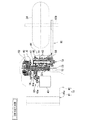
図1は、本発明の実施形態を示すハイブリッド二輪車の全体的な左側面図、図2は同じくハイブリッド自動二輪車の全体を一部を省略して示す平面図である。ハイブリッド二輪車は、エンジンを駆動源としたエンジン走行と、モータを駆動源としたEV(モータ)走行が可能な鞍乗型車両である。この鞍乗型車両は、オンロードタイプの自動二輪車、オフロードタイプの自動二輪車、スクータタイプの自動二輪車がある。ハイブリッド二輪車において、前、後、左、右はシートに着座したライダから見た方向に従う。   FIG. 1 is an overall left side view of a hybrid motorcycle showing an embodiment of the present invention, and FIG. 2 is a plan view showing the entire hybrid motorcycle with a part thereof omitted. A hybrid motorcycle is a straddle-type vehicle capable of running an engine using an engine as a drive source and running an EV (motor) using a motor as a drive source. The saddle riding type vehicle includes an on-road type motorcycle, an off-road type motorcycle, and a scooter type motorcycle. In a hybrid motorcycle, the front, rear, left, and right follow the direction seen from the rider seated on the seat.

ハイブリッド二輪車は、符号10で示すように、左右対をなすメインフレーム11と同じく左右対のシートフレーム12とから車体フレーム13が構成される。車体フレーム13のメインフレーム11にエンジンユニット14が搭載される。エンジンユニット14はメインフレーム11に懸架されて車体フレーム13の一部を構成している。   In the hybrid motorcycle, as indicated by reference numeral 10, a vehicle body frame 13 is composed of a pair of left and right seat frames 12 as well as a pair of left and right main frames 11. An engine unit 14 is mounted on the main frame 11 of the body frame 13. The engine unit 14 is suspended from the main frame 11 and constitutes a part of the vehicle body frame 13.

車体フレーム13の前端部にヘッドパイプ15が設けられ、このヘッドパイプ15に図3に示すアッパブラケット16およびロアブラケット17を介して左右対のフロントフォーク18が設けられる。アッパブラケット16には左右の操向ハンドル19が固定される一方、フロントフォーク18からのステアリングシャフト20下端に前輪21が軸支される。ハイブリッド二輪車10は操向ハンドル19の回動操作により操縦される。   A head pipe 15 is provided at the front end of the vehicle body frame 13, and a pair of left and right front forks 18 are provided on the head pipe 15 via an upper bracket 16 and a lower bracket 17 shown in FIG. 3. Left and right steering handles 19 are fixed to the upper bracket 16, while a front wheel 21 is pivotally supported at the lower end of the steering shaft 20 from the front fork 18. The hybrid motorcycle 10 is steered by turning the steering handle 19.

また、車体フレーム13はメインフレーム11の後部から下方向に延びるセンターフレーム部にピボット軸22が設けられ、このピボット軸22廻りにスイングアーム23が回動自在に設けられる。スイングアーム23の後端部には駆動輪である後輪24が軸支される。スイングアーム23とシートフレーム12との間にリアクッションユニット25によりスイングアーム23はピボット軸22廻りに昇降自在に支持される。   Further, the body frame 13 is provided with a pivot shaft 22 at a center frame portion extending downward from the rear portion of the main frame 11, and a swing arm 23 is rotatably provided around the pivot shaft 22. A rear wheel 24, which is a drive wheel, is pivotally supported at the rear end of the swing arm 23. The swing arm 23 is supported by the rear cushion unit 25 between the swing arm 23 and the seat frame 12 so as to be movable up and down around the pivot shaft 22.

一方、車体フレーム13のメインフレーム11上に燃料タンク27が跨って設置される。燃料タンク27はその前側下部にエアクリーナ28が設けられる。エアクリーナ28はエンジンユニット14の上方に位置される。エアクリーナ28には車両前方の空気取入口(インレット)29から取り入れられた空気が案内されるようになっている。   On the other hand, a fuel tank 27 is installed over the main frame 11 of the vehicle body frame 13. The fuel tank 27 is provided with an air cleaner 28 at the lower front side. The air cleaner 28 is positioned above the engine unit 14. The air cleaner 28 is configured to guide air taken from an air intake (inlet) 29 in front of the vehicle.

燃料タンク27の後方にはシート31が設けられる。シート31はシートフレーム12上に設置され、シート31下方にバッテリ32やインバータ33が設けられる。さらに、シート31の下方でかつバッテリ32の後方に、後述する電子制御スロットルコントローラユニット(ETVCU)35やトランスミッションコントロールユニット(TCU)36が設けられる。TCU36は、ハイブリッド二輪車10の車両のシフトチェンジを制御する制御ロジックを備えたコントロールユニットである。これらのETVCU35やTCU36およびインバータ33等は熱に弱い電気部品であるため、熱の影響を受けにくい場所に配置される。なお、符号38は燃料ポンプであり、符号39は未燃ガスや余剰燃料をストックするキャニスタである。インバータ33は、駆動モータ43が交流モータの場合に設けられ、直流モータの場合には、インバータ33の代りにバッテリが設けられる。   A seat 31 is provided behind the fuel tank 27. The seat 31 is installed on the seat frame 12, and a battery 32 and an inverter 33 are provided below the seat 31. Further, below the seat 31 and behind the battery 32, an electronic control throttle controller unit (ETVCU) 35 and a transmission control unit (TCU) 36, which will be described later, are provided. The TCU 36 is a control unit including a control logic that controls a shift change of the vehicle of the hybrid motorcycle 10. Since these ETVCU 35, TCU 36, inverter 33, and the like are electric components that are vulnerable to heat, they are arranged in a place that is not easily affected by heat. Reference numeral 38 denotes a fuel pump, and reference numeral 39 denotes a canister that stocks unburned gas and surplus fuel. The inverter 33 is provided when the drive motor 43 is an AC motor, and a battery is provided instead of the inverter 33 when the drive motor 43 is a DC motor.

ところで、車体フレーム13に搭載されるエンジンユニット14は、例えばユニットケース40上面にシリンダブロック41a、シリンダヘッドおよびヘッドカバーからなるシリンダアッセンブリ41が前傾して設置され、並列多気筒エンジン、例えば4気筒エンジンが構成される。エンジンケース40には、オートマチックマニュアルトランスミッション装置44(以下、AMTという。)が組み込まれている。AMT44は、クラッチ操作を必要とせずにマニュアルシフトを可能にし、シフトレバー操作フィーリングを改善し、クラッチ操作の煩わしさを無くしたセミオートマチックトランスミッション装置である。シリンダアッセンブリ41のシリンダヘッド後面に開口する4つの吸気ポートには電子制御スロットル装置45が接続される。シリンダヘッド前面に開口する排気ポートには排気管46が接続される。   By the way, the engine unit 14 mounted on the vehicle body frame 13 has, for example, a cylinder assembly 41 composed of a cylinder block 41a, a cylinder head, and a head cover, which is installed on the upper surface of the unit case 40 so as to be tilted forward. Is configured. The engine case 40 incorporates an automatic manual transmission device 44 (hereinafter referred to as AMT). The AMT 44 is a semi-automatic transmission device that enables manual shift without requiring clutch operation, improves the shift lever operation feeling, and eliminates the hassle of clutch operation. Electronically controlled throttle devices 45 are connected to the four intake ports that open to the rear surface of the cylinder head of the cylinder assembly 41. An exhaust pipe 46 is connected to an exhaust port that opens to the front surface of the cylinder head.

排気管46はシリンダアッセンブリ41の排気ポートから下方に延びて後方に折曲されて、後方に延びており、途中で集合されて排気チャンバ47が接続される。さらに、排気管は排気チャンバ46の側方から後方に延びてサイレンサ48に接続される。   The exhaust pipe 46 extends downward from the exhaust port of the cylinder assembly 41 and is bent rearward and extends rearward. The exhaust pipe 46 is gathered in the middle and connected to the exhaust chamber 47. Further, the exhaust pipe extends rearward from the side of the exhaust chamber 46 and is connected to the silencer 48.

AMT44は、図4ないし図9に示すように、エンジン回転、すなわちエンジンケース40の内部に軸支されたクランクシャフト50の回転を変速して後輪24に伝達するトランスミッション機構51と、クランクシャフト50の回転をトランスミッション機構51に対して伝達および遮断するクラッチ機構52と、クラッチ機構52を断続操作するクラッチアクチュエータ53と、トランスミッション機構51を変速操作するシフトチェンジアクチュエータ54とを備えて構成される。クラッチアクチュエータ53とシフトチェンジアクチュエータ54は、AMTアクチュエータを構成し、エンジンケース49に一体的に被装されるカバー、例えばスプロケットカバー56に設けられる。   As shown in FIGS. 4 to 9, the AMT 44 has a transmission mechanism 51 that shifts engine rotation, that is, rotation of the crankshaft 50 that is pivotally supported in the engine case 40 and transmits the transmission to the rear wheel 24, and the crankshaft 50. A clutch mechanism 52 that transmits and shuts off the rotation of the transmission mechanism 51, a clutch actuator 53 that intermittently operates the clutch mechanism 52, and a shift change actuator 54 that shifts the transmission mechanism 51. The clutch actuator 53 and the shift change actuator 54 constitute an AMT actuator, and are provided on a cover that is integrally mounted on the engine case 49, for example, a sprocket cover 56.

クラッチアクチュエータ53とシフトチェンジアクチュエータ54は、図6および図7に示すように、シリンダアッセンブリ41の後方で、かつエンジンケース40の左側面に設置されており、例えばエンジンケース40の左側面に被装されたスプロケットカバー55に固定される。スプロケットカバー55の内側にはエンジン出力をチェーンで後輪に伝えるドライブスプロケット(図8、図9参照)が収められている。   As shown in FIGS. 6 and 7, the clutch actuator 53 and the shift change actuator 54 are installed behind the cylinder assembly 41 and on the left side surface of the engine case 40. The sprocket cover 55 is fixed. Inside the sprocket cover 55 is housed a drive sprocket (see FIGS. 8 and 9) that transmits engine output to the rear wheels with a chain.

トランスミッション機構51は、一般のマニュアルトランスミッション装置に使用されているものと同様の構成である。即ち、クランクシャフト50の後方に平行に位置して車幅方向に延びるカウンタシャフト60およびドライブシャフト61と、図8および図9に示すように、カウンタシャフト60に軸装されて第1速から第6速に対応する6種類のドライブギア62と、ドライブシャフト61に軸装されて上記ドライブギア62に常時噛合する6種類のドリブンギア63とを備えている。なお、先述のドライブスプロケット56はドライブシャフト61の左端に回転一体に固定されている。   The transmission mechanism 51 has the same configuration as that used in a general manual transmission device. That is, the countershaft 60 and the drive shaft 61 that are located in parallel to the rear of the crankshaft 50 and extend in the vehicle width direction, and are mounted on the countershaft 60 as shown in FIGS. Six types of drive gears 62 corresponding to the sixth speed, and six types of driven gears 63 that are mounted on the drive shaft 61 and always mesh with the drive gear 62 are provided. The drive sprocket 56 described above is fixed to the left end of the drive shaft 61 so as to rotate together.

また、トランスミッション機構51は、図10および図12に示すように、シフトカム65によって動かされる複数のシフトフォーク66を備えている。従来から公知のように、シフトカム65は、段階的に回動することにより、複数のシフトフォーク66を介してドライブギア62およびドリブンギア63のいずれかに設けられた変速用ドッグ67(図10、図11参照)を軸方向に移動させて6種類のドライブギア62およびドリブンギア63の噛み合わせを選択する。   Further, as shown in FIGS. 10 and 12, the transmission mechanism 51 includes a plurality of shift forks 66 that are moved by a shift cam 65. As is known in the art, the shift cam 65 is rotated stepwise so that a shift dog 67 (FIG. 10, FIG. 10) is provided on either the drive gear 62 or the driven gear 63 via a plurality of shift forks 66. 11) is moved in the axial direction, and the meshing of the six types of drive gear 62 and driven gear 63 is selected.

クラッチ機構52は、公知の湿式多版クラッチであり、例えば図8、図9に示すように、カウンタシャフト60の右端側に設けられている。クラッチ機構52に回転一体に設けられたプライマリドリブンギア70が、クランクシャフト50、例えばエンジンクランクのクランクウェブの1つに設けられたプライマリドライブギア71に常時噛合している。   The clutch mechanism 52 is a known wet type multi-plate clutch, and is provided on the right end side of the counter shaft 60, for example, as shown in FIGS. A primary driven gear 70 provided integrally with the clutch mechanism 52 is always meshed with a primary drive gear 71 provided on a crankshaft 50, for example, one of the crank webs of an engine crank.

カウンタシャフト60は中空軸であり、その内部に摺動自在に挿入されたプッシュロッド72の左端部をクラッチアクチュエータ53が押圧していくと、クラッチ機構52の結合が徐々に解かれ、半クラッチ状態を経て結合が解除される。プッシュロッド72は、最大ストローク時にクラッチの回転トルクが0になる。クラッチ機構52が結合されるとエンジン回転がトランスミッション機構51のカウンタシャフト60に伝達され、クラッチ機構52が解除されるとエンジン回転がカウンタシャフト60に対して遮断される。   The counter shaft 60 is a hollow shaft, and when the clutch actuator 53 presses the left end portion of the push rod 72 slidably inserted therein, the coupling of the clutch mechanism 52 is gradually released, and a half-clutch state is achieved. After that, the connection is released. In the push rod 72, the rotational torque of the clutch becomes zero at the maximum stroke. When the clutch mechanism 52 is coupled, the engine rotation is transmitted to the counter shaft 60 of the transmission mechanism 51, and when the clutch mechanism 52 is released, the engine rotation is interrupted with respect to the counter shaft 60.

クラッチアクチュエータ53は、図11および図12に示すように、例えばサーボモータ73と、多段ギアからなる減速機構74と、カム軸状のクラッチレリーズカム75とを備えて構成されており、サーボモータ73の回転が減速機構74により減速されてクラッチレリーズカム75の回動に変換され、クラッチレリーズカム75の回動角が増すに従ってプッシュロッド72の押圧量が増大していく。   As shown in FIGS. 11 and 12, the clutch actuator 53 includes, for example, a servo motor 73, a speed reduction mechanism 74 including a multistage gear, and a cam shaft-like clutch release cam 75. Is decelerated by the speed reduction mechanism 74 and converted into rotation of the clutch release cam 75, and the pressing amount of the push rod 72 increases as the rotation angle of the clutch release cam 75 increases.

クラッチアクチュエータ53にはクラッチポジションセンサ76が設けられている。このクラッチポジションセンサ76は、例えば減速機構74のギアの回転角度を検知することによってクラッチ機構52の繋がり具合を判定するセンサであり、そのクラッチポジション信号CPが後述するトランスミッションコントロールユニット36(以下、TCUと略す)に受信される(図18参照)。   The clutch actuator 53 is provided with a clutch position sensor 76. The clutch position sensor 76 is a sensor that determines the degree of engagement of the clutch mechanism 52 by detecting, for example, the rotation angle of the gear of the speed reduction mechanism 74, and the clutch position signal CP is a transmission control unit 36 (hereinafter referred to as TCU) to be described later. (Refer to FIG. 18).

シフトチェンジアクチュエータ54は、図12および図13に示すように、例えばサーボモータ80と、多段ギアからなる減速機構81とを備えて構成される。サーボモータ80の回転が減速機構81により減速されてシフトチェンジシャフト82を回動させ、シフトチェンジシャフト82の回動がシフトギア83によってシフトカム65に伝達されるようになっている。   As shown in FIGS. 12 and 13, the shift change actuator 54 includes, for example, a servo motor 80 and a speed reduction mechanism 81 composed of a multistage gear. The rotation of the servo motor 80 is decelerated by the speed reduction mechanism 81 to rotate the shift change shaft 82, and the rotation of the shift change shaft 82 is transmitted to the shift cam 65 by the shift gear 83.

また、シフトチェンジアクチュエータ54には、図12に示すように、シフトポジションセンサ84が設けられている。このシフトポジションセンサ84は、例えばシフトチェンジシャフト82の回動角度を検知することによってギアポジションを判定するセンサであり、そのシフトポジション信号SPが後述するTCU36に受信される(図18参照)。   Further, the shift change actuator 54 is provided with a shift position sensor 84 as shown in FIG. The shift position sensor 84 is a sensor that determines the gear position by detecting the rotation angle of the shift change shaft 82, for example, and the shift position signal SP is received by the TCU 36 described later (see FIG. 18).

一方、自動二輪車の車体フレーム13には、運転者が足を載せる左右一対のフットレスト85が、エンジンユニット14の後方に位置するように設けられる(図1、図12参照)。そして、エンジンユニット14の左側面には、左側のフットレスト85の前下方に位置するようにシフトレバー86が設けられる。運転者は、左側のフットレスト85に載せた左足の爪先でシフトレバー86を上方または下方に繰り返し回動操作してAMT44のシフト操作を行なう。例えば、シフトレバー86を上方に回動させるとAMT44がシフトアップし、下方に回動させるとAMT44がシフトダウンする。   On the other hand, the body frame 13 of the motorcycle is provided with a pair of left and right footrests 85 on which the driver puts his / her feet so as to be positioned behind the engine unit 14 (see FIGS. 1 and 12). A shift lever 86 is provided on the left side surface of the engine unit 14 so as to be positioned in front of and under the left footrest 85. The driver performs the shift operation of the AMT 44 by repeatedly rotating the shift lever 86 upward or downward with the toe of the left foot placed on the left footrest 85. For example, when the shift lever 86 is rotated upward, the AMT 44 is shifted up, and when it is rotated downward, the AMT 44 is shifted down.

図1、図2、図12および図14、特に図14に示すように示すように、シフトレバー86は、その根元の回動軸(シフトシャフト)87が、エンジンケース40の左下側面に取り付けられたシフトレバーブラケット88に軸支されており、回動軸87にはリターンスプリング(図示せず)が軸装されている。リターンスプリングは、シフトレバー86の非操作時には、シフトレバー86を図14に示す回動開始位置86Nに保持する。   As shown in FIGS. 1, 2, 12, and 14, particularly FIG. 14, the shift lever 86 has a pivot shaft 87 (shift shaft) attached to the lower left side surface of the engine case 40. The shift lever bracket 88 is pivotally supported, and a return spring (not shown) is mounted on the rotation shaft 87. The return spring holds the shift lever 86 at the rotation start position 86N shown in FIG. 14 when the shift lever 86 is not operated.

また、シフトレバーブラケット88には、図1および図14に示すように、シフトレバー86と共に、シフトレバー回動角センサ(シフトレバー回動検出部)90と、荷重特性付与機構89とが設置される。シフトレバー回動角センサ90は、シフトレバー86の回動角度を検知することにより、シフトレバー86の回動操作が開始されたことを検出してシフト検出信号SU,SDを発信するセンサである。なお、シフトレバー回動角センサ90としては、回動角センサに限らず、例えば荷重センサを用いてもよい。また、荷重特性付与機構89は、後述するようにシフトレバー86の回動に所定の荷重特性を付与する機構である。   As shown in FIGS. 1 and 14, the shift lever bracket 88 is provided with a shift lever 86, a shift lever rotation angle sensor (shift lever rotation detection unit) 90, and a load characteristic applying mechanism 89. The The shift lever rotation angle sensor 90 is a sensor that detects the rotation angle of the shift lever 86 to detect that the rotation operation of the shift lever 86 is started and transmits shift detection signals SU and SD. . The shift lever rotation angle sensor 90 is not limited to the rotation angle sensor, and for example, a load sensor may be used. The load characteristic imparting mechanism 89 is a mechanism that imparts a predetermined load characteristic to the rotation of the shift lever 86 as will be described later.

シフトレバー86は、図14に示すように、回動開始位置86Nから、上方の回動終点位置86UPと、下方の回動終点位置86DOWNまで回動することができる。また、回動開始位置86Nと、上下の回動終点位置86UP,86DOWNとの間には、それぞれ回動検出位置PUとPDが設定されている。これらの回動検出位置PU,PDは、それぞれ回動終点位置86UP,86DOWNよりも回動開始位置86Nにやや近い位置に設けられている。   As shown in FIG. 14, the shift lever 86 can rotate from a rotation start position 86N to an upper rotation end position 86UP and a lower rotation end position 86DOWN. Further, rotation detection positions PU and PD are set between the rotation start position 86N and the upper and lower rotation end positions 86UP and 86DOWN, respectively. These rotation detection positions PU and PD are provided at positions slightly closer to the rotation start position 86N than the rotation end positions 86UP and 86DOWN, respectively.

シフトレバー86が回動検出位置PUを通過する時には、シフトレバー回動角センサ90がシフトアップを伝えるシフト検出信号SUを発信し、シフトレバー86が回動検出位置PDを通過する時には、シフトレバー回動角センサ90がシフトダウンを伝えるシフト検出信号SDを発信する。これらのシフト検出信号SU,SDは、図18に示すTCU36に受信される。   When the shift lever 86 passes through the rotation detection position PU, the shift lever rotation angle sensor 90 transmits a shift detection signal SU that tells upshifting. When the shift lever 86 passes through the rotation detection position PD, the shift lever 86 The rotation angle sensor 90 transmits a shift detection signal SD that conveys the downshift. These shift detection signals SU and SD are received by the TCU 36 shown in FIG.

荷重特性付与機構89は、図14に示すように、シフトレバー86が回動開始位置86Nから回動終点位置86UPに1度回動操作されると、カムプレート(図示せず)を所要角度、例えば60度回動させる。   As shown in FIG. 14, when the shift lever 86 is rotated once from the rotation start position 86N to the rotation end point position 86UP, the load characteristic imparting mechanism 89 moves the cam plate (not shown) to the required angle, For example, it is rotated 60 degrees.

シフトレバー86が回動開始位置86Nから回動終点位置86DOWNに1度回動操作されると、カムプレートを所要角度、例えば60度回動させる。   When the shift lever 86 is rotated once from the rotation start position 86N to the rotation end position 86DOWN, the cam plate is rotated by a required angle, for example, 60 degrees.

さらに、シフトレバー86を回動開始位置86Nから回動終点位置86UPまたは回動終点位置86DOWNに複数回、連続的に回動させると、その回動回数だけカムプレートが60度ずつ時計方向または反時計方向に節度が付与されて断続的(間欠的)に回動操作される。   Further, when the shift lever 86 is continuously rotated a plurality of times from the rotation start position 86N to the rotation end position 86UP or the rotation end position 86DOWN, the cam plate is rotated clockwise or counterclockwise by 60 degrees by the number of rotations. Moderation is given in the clockwise direction and the operation is intermittently (intermittent).

また、シフトレバー86が回動開始位置86Nから回動終点位置86UPまたは86DOWNに回動するまでの間に、荷重特性付与機構89によってシフトレバー86の反力に山型の荷重特性が図15に示されるように付与される。   In addition, the load characteristic imparting mechanism 89 shows a mountain-shaped load characteristic in response to the reaction force of the shift lever 86 until the shift lever 86 rotates from the rotation start position 86N to the rotation end position 86UP or 86DOWN. Granted as shown.

そして、この山型の荷重特性の最大荷重点Wmaxの発生位置は、シフトレバー86の回動検出位置PU,PDの位置に略一致するように設定されている。このため、シフトレバー86の反力は、回動開始位置86Nから回動検出位置PU,PDにかけて大きくなり、回動検出位置PU,PDを超えてからは小さくなる。そして、最も反力が高くなった時に、シフトレバー回動角センサ90からシフトアップまたはシフトダウンのシフト検出信号SUまたはSDがTCU36に送信される。   The generation position of the maximum load point Wmax of the mountain-shaped load characteristic is set so as to substantially coincide with the positions of the rotation detection positions PU and PD of the shift lever 86. For this reason, the reaction force of the shift lever 86 increases from the rotation start position 86N to the rotation detection positions PU and PD, and decreases after exceeding the rotation detection positions PU and PD. When the reaction force becomes the highest, a shift detection signal SU or SD for upshifting or downshifting is transmitted from the shift lever rotation angle sensor 90 to the TCU 36.

[AMTアクチュエータとEV走行用モータとの配置構成]
ハイブリッド二輪車10は、図1に示すように、車両側面視でエンジンユニット14のシリンダアッセンブリ41の背側に、かつエンジンケース40の上方にEV走行用モータ(駆動モータ)43が設けられる。EV走行用モータ43は電動アシストモータを構成しており、図2、図5および図7に示すように、シリンダアッセンブリ41のシリンダブロック後方でかつエンジンケース40上方の比較的スペースの空いている場所に設けられる。
[Arrangement Configuration of AMT Actuator and EV Traveling Motor]
As shown in FIG. 1, the hybrid motorcycle 10 is provided with an EV traveling motor (drive motor) 43 on the back side of the cylinder assembly 41 of the engine unit 14 and above the engine case 40 in a side view of the vehicle. The EV traveling motor 43 constitutes an electric assist motor. As shown in FIGS. 2, 5, and 7, a relatively vacant space behind the cylinder block of the cylinder assembly 41 and above the engine case 40. Is provided.

したがって、燃料タンク27の容量減少を無くしたり、最小限に抑えながらEV走行用モータ43で駆動力アシストを行なうことができる。EV走行用モータ43は、AMTアクチュエータであるクラッチアクチュエータ53およびシフトチェンジアクチュエータ54を避けるようにAMTアクチュエータ53,54の車両幅方向内側に配置される。EV走行用モータ43は、車両側面視でシリンダアッセンブリ41のシリンダブロック後方でかつエンジンケース40のクランクケース上方、さらに左右対のメインフレーム11,11間の内側に設置される。EV走行用モータ43は、車両側面視でメインフレーム11より上方に突出することなく、また、車両平面視で図2および図5に示すように車両中心線CLを跨って配置される。   Therefore, the driving force assist can be performed by the EV traveling motor 43 while the capacity reduction of the fuel tank 27 is eliminated or minimized. The EV traveling motor 43 is disposed on the inner side in the vehicle width direction of the AMT actuators 53 and 54 so as to avoid the clutch actuator 53 and the shift change actuator 54 which are AMT actuators. The EV traveling motor 43 is installed behind the cylinder block of the cylinder assembly 41 in the vehicle side view, above the crankcase of the engine case 40, and inside the pair of left and right main frames 11, 11. The EV traveling motor 43 does not protrude upward from the main frame 11 in the side view of the vehicle, and is disposed across the vehicle center line CL as shown in FIGS. 2 and 5 in the vehicle plan view.

また、EV走行用モータ43は、車両側面視でクラッチ室(クラッチ機構52)側にオフセットして配置され、車両中心線CLを跨いで設けられるため、クラッチアクチュエータ53およびシフトチェンジアクチュエータ54をエンジン中心側に近付けてオフセット配置することができ、エンジン幅方向寸法を小さくすることができる。したがって、車両のコンパクト化を図りながらシングルクラッチ式AMT44を構成することができる。クラッチアクチュエータ53は、図5および図7に示すように、クラッチレリーズアームシャフト軸53a上に設けられて、エンジンの最大幅を超えないエンジン幅の範囲に設置される。このため、車両転倒時のAMTアクチュエータの破損や走行に伴う空力特性の悪化を防ぐことができる。   Further, since the EV travel motor 43 is disposed offset to the clutch chamber (clutch mechanism 52) side in a side view of the vehicle and is provided across the vehicle center line CL, the clutch actuator 53 and the shift change actuator 54 are arranged at the engine center. It can be arranged close to the side and offset, and the size in the engine width direction can be reduced. Therefore, the single clutch AMT 44 can be configured while reducing the size of the vehicle. As shown in FIGS. 5 and 7, the clutch actuator 53 is provided on the clutch release arm shaft shaft 53 a and is installed in an engine width range that does not exceed the maximum width of the engine. For this reason, it is possible to prevent the AMT actuator from being damaged when the vehicle falls and deterioration of the aerodynamic characteristics accompanying traveling.

駆動モータ43のモータ軸43aは、図9、図16および図17に示すように、多段の減速ギア列の減速機構93を介してトランスミッション機構51のカウンタシャフト60上のドライブギア94にギア連結され、モータ駆動力伝達機構96が構成される。このドライブギア94はカウンタシャフト60に直結されて1速ドライブギアを構成している。1速ドライブギア94はドライブシャフト61に回転自由に設けられた1速ドリブンギア95とギア連結される。なお、減速機構93は2段の減速抑制を備えた例を説明したが、1段の減速ギアであってもよい。駆動モータ43のモータ駆動力は、図9に示すように、減速機構93からカウンタシャフト60上のドライブギア94およびトランスミッション機構51を経て後輪24駆動用のチェーン・スプロケット機構92に伝達される。 The motor shaft 43a of the drive motor 43 is gear-coupled to a drive gear 94 on the counter shaft 60 of the transmission mechanism 51 via a reduction mechanism 93 of a multi-stage reduction gear train, as shown in FIGS. A motor driving force transmission mechanism 96 is configured. The drive gear 94 is directly connected to the counter shaft 60 to constitute a first speed drive gear. The first-speed drive gear 94 is gear-coupled to a first-speed driven gear 95 that is rotatably provided on the drive shaft 61. In addition, although the deceleration mechanism 93 demonstrated the example provided with 2 steps | paragraphs of deceleration suppression, a 1 step | paragraph reduction gear may be sufficient. As shown in FIG. 9, the motor driving force of the drive motor 43 is transmitted from the speed reduction mechanism 93 to the chain sprocket mechanism 92 for driving the rear wheels 24 through the drive gear 94 and the transmission mechanism 51 on the counter shaft 60.

EV走行用モータ43は、図2および図5に示すように、車両平面視において、車両中心線CLを跨ぐように車両幅方向を向いて車両中心線側に設置され、対をなすメインフレーム11,11間に囲まれてシリンダブロックの後方でクランクケース上面に設けられる。車両の上面視や後面視において、車両幅方向のエンジン全幅より内側にAMT44および駆動モータ43が入るように配置される。このAMT44と駆動モータ43の配置構成により、エンジン寸法を増大させずにAMT44とEVモータである駆動モータ43との配置を両立させることができる。   As shown in FIGS. 2 and 5, the EV traveling motor 43 is installed on the vehicle center line side facing the vehicle width direction so as to straddle the vehicle center line CL in a plan view of the vehicle, and forms a pair of main frames 11. , 11 is provided on the upper surface of the crankcase behind the cylinder block. The AMT 44 and the drive motor 43 are arranged so as to enter inside the entire engine width in the vehicle width direction in a top view and a rear view of the vehicle. With the arrangement configuration of the AMT 44 and the drive motor 43, the arrangement of the AMT 44 and the drive motor 43 that is an EV motor can be made compatible without increasing the engine size.

また、重量物である駆動モータ43を、シリンダアッセンブリ41の後方で車両前後左右中心の重心付近に配置できるため、マスの集中化が図れ、慣性モーメントの増大を抑えて操縦安定性の悪化を抑えることができる。   In addition, since the heavy drive motor 43 can be disposed in the vicinity of the center of gravity of the front, rear, left and right of the vehicle behind the cylinder assembly 41, the mass can be concentrated and the increase of the moment of inertia can be suppressed to suppress the deterioration of the steering stability. be able to.

さらに、モータ駆動力伝達機構96は、図16および図17に示すように、EV走行用モータ43のモータ軸43a、減速機構93のアイドルギア93aを軸支するアイドル軸93bおよびトランスミッション機構51のカウンタシャフト60軸およびドライブシャフト軸61の各ギアを結ぶ各軸が略直線上でコンパクトに配置される。このため、エンジンの小型・コンパクト化を図ることができ、軽量化に貢献することができる。   Further, as shown in FIGS. 16 and 17, the motor driving force transmission mechanism 96 includes a motor shaft 43a of the EV traveling motor 43, an idle shaft 93b that supports the idle gear 93a of the speed reduction mechanism 93, and a counter of the transmission mechanism 51. The shafts connecting the gears of the shaft 60 axis and the drive shaft shaft 61 are arranged compactly on a substantially straight line. Therefore, the engine can be reduced in size and size and contribute to weight reduction.

一方、重量物であるEV走行用モータ43を図1、図2および図5に示すように、車両の前後左右の中心で、重心付近に集中的に配置することができ、車両の重量バランスを左右で安定化させ、慣性モーメントの増大を抑えて操縦安定性を確保し、向上させることができる。   On the other hand, as shown in FIGS. 1, 2, and 5, the EV traveling motor 43, which is a heavy object, can be intensively arranged near the center of gravity at the front, rear, left, and right centers of the vehicle. It is possible to stabilize and improve the steering stability by suppressing the increase of the moment of inertia by stabilizing the left and right.

[AMTの構成]
図18は、AMT44の全体構成を示すブロック図である。AMT44は、ハイブリッド二輪車10のシフトチェンジ制御を行なう制御ロジックを備えたトランスミッションコントロールユニット(TCU)36を備える。
[Configuration of AMT]
FIG. 18 is a block diagram showing the overall configuration of the AMT 44. The AMT 44 includes a transmission control unit (TCU) 36 including a control logic for performing shift change control of the hybrid motorcycle 10.

AMT44の制御部であるTCU36には、AMTアクチュエータであるクラッチアクチュエータ53およびシフトチェンジアクチュエータ54と、エンジンコントロールユニット97と、電子制御スロットルコントローラ98とEV走行コントロールユニット99とが接続され、それぞれTCU36から発信される作動信号A1〜A5に基づいて作動する。   A clutch actuator 53 and a shift change actuator 54 which are AMT actuators, an engine control unit 97, an electronic control throttle controller 98 and an EV traveling control unit 99 are connected to the TCU 36 which is a control unit of the AMT 44. The operation is performed based on the operation signals A1 to A5.

また、TCU36には、クラッチアクチュエータポジションセンサ76と、シフトアクチュエータポジションセンサ84と、シフトレバー回動角センサ90とが接続され、クラッチアクチュエータポジションセンサ76から発信されるクラッチポジション信号CPと、シフトアクチュエータポジションセンサ84から発信されるシフトポジション信号SPと、シフトレバー回動角(または荷重)センサ90から発信されるシフト検出信号SU,SDとが、それぞれTCU36に入力される。   Further, a clutch actuator position sensor 76, a shift actuator position sensor 84, and a shift lever rotation angle sensor 90 are connected to the TCU 36, and a clutch position signal CP transmitted from the clutch actuator position sensor 76, and a shift actuator position. A shift position signal SP transmitted from the sensor 84 and shift detection signals SU and SD transmitted from the shift lever rotation angle (or load) sensor 90 are input to the TCU 36, respectively.

さらに、TCU36には、カウンタシャフト60の回転速度信号CSを発信するカウンタシャフトスピードセンサ100と、自動二輪車の車速信号VSを発信する車速センサ101と、自動二輪車の運転者が操作するスロットルグリップの開度信号TPSを発信するスロットルポジションセンサ102と、電子制御スロットルの開度信号APSを発信するアクセルポジションセンサ103と、トランスミッション機構51のギアポジション信号GPSを発信するシフトカムポジションセンサ104と、燃料噴射システムに必要なその他各種の信号ETCを発信するエンジン運転状態検知用センサ類105(冷却水温度センサ、吸気温度センサ、油温センサ、Oセンサ等)と、が接続されている。 Further, the TCU 36 includes a countershaft speed sensor 100 that transmits a rotational speed signal CS of the countershaft 60, a vehicle speed sensor 101 that transmits a vehicle speed signal VS of a motorcycle, and an opening of a throttle grip that is operated by a motorcycle driver. A throttle position sensor 102 that transmits a degree signal TPS, an accelerator position sensor 103 that transmits an opening signal APS of an electronically controlled throttle, a shift cam position sensor 104 that transmits a gear position signal GPS of the transmission mechanism 51, and a fuel injection system. Engine operating state detection sensors 105 (a cooling water temperature sensor, an intake air temperature sensor, an oil temperature sensor, an O 2 sensor, etc.) that transmit various other necessary signals ETC are connected.

TCU36は、シフトレバー86(図14参照)の回動操作に伴いシフトレバー回動角センサ90から送信されるシフト検出信号SUまたはSDを受信すると、各センサ類74,80,90,100〜105から送信される各種の信号CP,SP,CS,VS,TPS,APS,GPS,ETCを参照しながらエンジンユニット14の出力を制御するとともに、クラッチアクチュエータ53とシフトチェンジアクチュエータ54とのAMTアクチュエータを制御して変速を実行する。   When the TCU 36 receives the shift detection signal SU or SD transmitted from the shift lever rotation angle sensor 90 in accordance with the rotation operation of the shift lever 86 (see FIG. 14), each sensor 74, 80, 90, 100 to 105 is received. The output of the engine unit 14 is controlled with reference to various signals CP, SP, CS, VS, TPS, APS, GPS, ETC transmitted from the AMT, and the AMT actuator of the clutch actuator 53 and the shift change actuator 54 is controlled. To change the speed.

この時、TCU36は、シフト検出信号SU,SDを受信してから、シフトレバー86が回動終点位置86UP,86DOWNまで回動するまでの間に、クラッチアクチュエータ53およびシフトチェンジアクチュエータ54を制御して変速を完了させる。   At this time, the TCU 36 controls the clutch actuator 53 and the shift change actuator 54 after the shift detection signal SU, SD is received and before the shift lever 86 is rotated to the rotation end positions 86UP, 86DOWN. Complete shifting.

即ち、TCU36は、シフト検出信号SU,SDを受信すると同時に、クラッチアクチュエータ53を作動させてクラッチ機構52の接続を解除し、次にシフトチェンジアクチュエータ54を作動させてトランスミッション機構51のシフトカム65(図10参照)を回動させ、変速を行わせた後、再度クラッチアクチュエータ53を作動させてクラッチ機構52を接続する。   That is, the TCU 36 receives the shift detection signals SU and SD, and simultaneously operates the clutch actuator 53 to release the clutch mechanism 52 and then operates the shift change actuator 54 to shift the shift cam 65 (see FIG. 10) is rotated to change the speed, and then the clutch actuator 53 is operated again to connect the clutch mechanism 52.

TCU36は、シフトチェンジアクチュエータ54を作動させて変速を行う際に、各種のセンサの入力信号からエンジンユニット14の運転状況を判断し、例えばシフトアップ時にはエンジンコントロールユニット97の、例えばイグニッションコントローラを制御して点火カット(間引き点火)や点火時期の遅角化等を行い、シフトダウン時には電子制御スロットルコントローラ98を制御してブリッピング(空吹かし)を行う。これらにより、ドライブギア62とドリブンギア63とに設けられた変速用ドッグ67に加わる荷重が抜かれ(図10参照)、変速がスムーズに行われて変速に要する時間が短縮される。   The TCU 36 determines the operation status of the engine unit 14 from the input signals of various sensors when shifting by operating the shift change actuator 54, and controls, for example, the ignition controller of the engine control unit 97 at the time of shift up. Then, ignition cut (decimation ignition), ignition timing retarding, etc. are performed, and at the time of downshifting, the electronic control throttle controller 98 is controlled to perform blipping (idling). As a result, the load applied to the shift dog 67 provided in the drive gear 62 and the driven gear 63 is removed (see FIG. 10), the shift is performed smoothly, and the time required for the shift is shortened.

また、TCU36は、変速が完了してクラッチ機構52を接続させる時に、各種のセンサの入力信号に基づいて、クラッチ機構52の接続に伴う変速ショックが大きいか否かを判定し、変速ショックが大きい状況である場合には、クラッチアクチュエータ53を制御してクラッチ機構52の接続をゆっくり行い、半クラッチ状態を長くすることによって変速ショックを低減させる。   Further, when the shift is completed and the clutch mechanism 52 is connected, the TCU 36 determines whether or not the shift shock accompanying the connection of the clutch mechanism 52 is large based on the input signals of various sensors, and the shift shock is large. If this is the case, the clutch actuator 53 is controlled to slowly connect the clutch mechanism 52, and the shift shock is reduced by lengthening the half-clutch state.

[エンジン始動、エンジン走行、エンジン駆動による発電およびEV走行]
ハイブリッド二輪車10は、図9に示すように、EV走行用モータ43のモータ駆動により、モータ軸43aは減速機構93を介してトランスミッション機構51を構成するカウンタシャフト60上に直結された1速ドライブギアに駆動力が伝えられる。EV走行用モータ43から1速ドライブギア94に伝達されるモータ駆動力(トルク)は、ギアポジションがN(ニュートラル)ポジション以外の状態でトランスミッション機構51に伝達される。トランスミッション機構51はシフトドッグ67が備えられており、ドッグを有するミッションギア構造がEV走行用モータ43からクラッチの役割を果す。このため、EV走行用モータ43のモータ作動によるEV走行とエンジン駆動に伴うエンジン走行との切替をトランスミッション機構(T/M)のギアドッグ嵌合およびクラッチ機構52の作動によって切替が可能となる。
[Engine start-up, engine running, engine-driven power generation and EV running]
As shown in FIG. 9, the hybrid motorcycle 10 is a first-speed drive gear in which the motor shaft 43 a is directly connected to the counter shaft 60 constituting the transmission mechanism 51 via the speed reduction mechanism 93 by the motor driving of the EV traveling motor 43. The driving force is transmitted to. The motor driving force (torque) transmitted from the EV traveling motor 43 to the first speed drive gear 94 is transmitted to the transmission mechanism 51 in a state where the gear position is other than the N (neutral) position. The transmission mechanism 51 is provided with a shift dog 67, and a transmission gear structure having a dog plays a role of a clutch from the EV traveling motor 43. For this reason, switching between EV traveling by the motor operation of the EV traveling motor 43 and engine traveling accompanying driving of the engine can be switched by the gear dog fitting of the transmission mechanism (T / M) and the operation of the clutch mechanism 52.

ハイブリッド二輪車10は、並列多気筒エンジンのエンジン駆動によるエンジン走行(図8参照)の他に、EV走行用モータ43のモータ駆動によるEV走行(図9参照)、モータ発電およびエンジン始動が可能となる。   The hybrid motorcycle 10 can perform EV traveling (see FIG. 9), motor power generation, and engine start by motor driving of the EV traveling motor 43, in addition to engine traveling (see FIG. 8) driven by an engine of a parallel multi-cylinder engine. .

[モータ発電する場合]
クラッチ機構52が繋がっている(結合される)状態で並列多気筒エンジン(エンジンユニット14)が駆動されると、図8に示すように、エンジン駆動力は、クラッチ機構52を介してカウンタシャフト60が回転され、トランスミッション機構51を介して後輪24に伝達され、エンジン走行が行なわれる。その際、カウンタシャフト60上の1速ドライブギア94はカウンタシャフト60と常に同じ回転数で回転される。したがって、エンジン駆動に伴うエンジン回転によりEV走行用モータ43のモータ軸43aは常に回転駆動され、EV走行用モータ43によるモータ発電が常に可能となる。モータ発電によりEV走行用モータ43は発電機の役割を果し、EVアシストモータとして機能する。
[When generating motor power]
When the parallel multi-cylinder engine (engine unit 14) is driven in a state where the clutch mechanism 52 is connected (coupled), the engine driving force is transmitted to the counter shaft 60 via the clutch mechanism 52 as shown in FIG. Is transmitted to the rear wheel 24 via the transmission mechanism 51, and the engine travels. At that time, the first-speed drive gear 94 on the counter shaft 60 is always rotated at the same rotational speed as the counter shaft 60. Therefore, the motor shaft 43a of the EV traveling motor 43 is always rotationally driven by the engine rotation accompanying the engine driving, and the motor power generation by the EV traveling motor 43 is always possible. Due to the motor power generation, the EV running motor 43 serves as a generator and functions as an EV assist motor.

また、エンジン駆動に伴ってEV走行用モータ43であるEVモータはモータ発電が行なわれるため、副次的効果として、エンジンユニット14のクランクシャフト50上に設けられた発電用マグネット108(図8参照)は小さくてもよく、また廃止することができる。   Further, since the EV motor, which is the EV traveling motor 43, is driven by the engine, motor power generation is performed. As a secondary effect, a power generation magnet 108 provided on the crankshaft 50 of the engine unit 14 (see FIG. 8). ) Can be small and can be abolished.

[EV走行する場合]
EV走行は駆動モータ43のモータ駆動により、基本的には、発電する場合と同様、常に可能である。EV走行用モータである駆動モータ43がモータ駆動すると、モータ駆動力(駆動トルク)は、図9に示すように、減速機構93を介してアイドルギア93aからカウンタシャフト60上のドライブギア94、例えば1速ドライブギアに伝達され、続いてトランスミッション機構51によりドライブシャフト61上のドリブンギア63に伝えられ、さらに、チェーン・スプロケット機構92を経て伝達され、後輪24を駆動し、EV走行させる。
[When running on EV]
EV travel is always possible by driving the motor of the drive motor 43, basically as in the case of power generation. When the drive motor 43, which is an EV travel motor, drives the motor, the motor drive force (drive torque) is driven from the idle gear 93a to the drive gear 94 on the countershaft 60 via the reduction mechanism 93, for example, as shown in FIG. It is transmitted to the first-speed drive gear, then transmitted to the driven gear 63 on the drive shaft 61 by the transmission mechanism 51, and further transmitted via the chain / sprocket mechanism 92 to drive the rear wheel 24 and cause EV travel.

EV走行の場合、エンジン走行の場合と同様、トランスミッション機構51はカウンタシャフト60上の各ドライブギア62とドライブシャフト61上の各ドリブンギア63とは、選択的に組み合されて変速操作される。EV走行の場合もエンジン走行の場合も、トランスミッション機構51やチェーン・スプロケット機構92の動力伝達機構を共通に用いることができ、駆動モータ43の消費電力、効率化を図ることができる。   In the case of EV traveling, as in the case of engine traveling, in the transmission mechanism 51, each drive gear 62 on the countershaft 60 and each driven gear 63 on the drive shaft 61 are selectively combined to perform a speed change operation. In both EV traveling and engine traveling, the power transmission mechanisms of the transmission mechanism 51 and the chain / sprocket mechanism 92 can be used in common, and the power consumption and efficiency of the drive motor 43 can be improved.

[エンジン始動]
エンジン始動は、ハイブリッド二輪車10の右側操向ハンドル19の基部に設けられたスタータスイッチ110(図19参照)をON操作することにより行なうことができる。スタータスイッチ110をON操作し、クラッチ機構52を継いだ(結合させたON)状態でEV走行用モータ43をモータ駆動させると、カウンタシャフト軸60の回転が、クラッチ機構52を介してクランクシャフト50に伝達され、クランクシャフト50を回転させることができ、エンジンクランクを回転駆動させてエンジンを始動させる。クラッチ機構52を繋いでいる状態であれば、カウンタシャフト軸60を回転させれば、クランクシャフト50を回転させることができ、エンジンを始動させることができるので、全てのギアポジションにてエンジン始動が可能となる。N(ニュートラル)ポジションであれば、車両停止状態でエンジン始動が可能となる。
[engine start]
The engine can be started by turning on a starter switch 110 (see FIG. 19) provided at the base of the right steering handle 19 of the hybrid motorcycle 10. When the starter switch 110 is turned on and the EV travel motor 43 is driven with the clutch mechanism 52 engaged (connected ON), the rotation of the countershaft shaft 60 causes the crankshaft 50 to rotate through the clutch mechanism 52. The crankshaft 50 can be rotated, and the engine is started by rotating the engine crank. If the clutch mechanism 52 is connected, the crankshaft 50 can be rotated and the engine can be started by rotating the countershaft shaft 60, so that the engine can be started at all gear positions. It becomes possible. In the N (neutral) position, the engine can be started when the vehicle is stopped.

一方、ハイブリッド二輪車10の右側操向ハンドル19の基部には、図19に示すアクセルグリップセンサ109の他に、スタータスイッチ110、走行モード切替スイッチ111およびキルスイッチ112が設けられる。切替スイッチ111はモータ駆動力によるEV走行とエンジン駆動によるエンジン走行とを切り替えるものである。   On the other hand, in addition to the accelerator grip sensor 109 shown in FIG. 19, a starter switch 110, a travel mode changeover switch 111, and a kill switch 112 are provided at the base of the right steering handle 19 of the hybrid motorcycle 10. The changeover switch 111 switches between EV traveling by motor driving force and engine traveling by engine driving.

切替スイッチ111を矢印A方向にON操作させると、駆動モータ43がモータ駆動され、モータ駆動力は、図9に示すように、減速機構93、トランスミッション機構51、チェーン・スプロケット機構92を経て後輪24に伝達され、後輪24を走行駆動させる(EV走行)。   When the changeover switch 111 is turned ON in the direction of arrow A, the drive motor 43 is driven by the motor, and the motor drive force passes through the speed reduction mechanism 93, the transmission mechanism 51, and the chain / sprocket mechanism 92, as shown in FIG. 24, the rear wheel 24 is driven to travel (EV traveling).

このEV走行時に、クラッチ機構52を繋ぐと、EVモータである駆動モータ43のモータ駆動力はクランクシャフト50にも伝達され、クランクシャフト50を回転させる。クランクシャフト50の回転により、発電用マグネット108(図8参照)が回転して発電し、発生した電力をバッテリ32に充電している。   When the clutch mechanism 52 is connected during the EV traveling, the motor driving force of the drive motor 43 that is an EV motor is also transmitted to the crankshaft 50 to rotate the crankshaft 50. Due to the rotation of the crankshaft 50, the power generation magnet 108 (see FIG. 8) rotates to generate power, and the generated power is charged in the battery 32.

また、切替スイッチ111を矢印B方向に切り替えると、ハイブリッド二輪車10はEV走行からエンジン走行に切り替わる。エンジン走行では、図8に示すように並列多気筒エンジン(エンジンユニット14)のエンジン駆動により、エンジン駆動力は、プライマリドライブギア71からプライマリドリブンギア70、クラッチ機構52を経てカウンタシャフト60に伝達され、続いてカウンタシャフト60からトランスミッション機構51、チェーン・スプロケット機構92を経て後輪24に伝えられ、後輪24を駆動させる(エンジン走行)。   When the changeover switch 111 is switched in the direction of arrow B, the hybrid two-wheeled vehicle 10 is switched from EV traveling to engine traveling. In engine running, the engine driving force is transmitted from the primary drive gear 71 to the counter shaft 60 via the primary driven gear 70 and the clutch mechanism 52 by driving the parallel multi-cylinder engine (engine unit 14) as shown in FIG. Subsequently, the transmission is transmitted from the counter shaft 60 to the rear wheel 24 via the transmission mechanism 51 and the chain / sprocket mechanism 92 to drive the rear wheel 24 (engine running).

さらに、エンジン走行時には、トランスミッション機構51のカウンタシャフト60が常に回転しているので、エンジン駆動力が1速ドライブギア94から減速機構93を経てモータ軸43aに伝達され、EV走行用モータ43は常時回転してモータ発電される。EV走行用モータ43が交流モータの場合は発生した交流の電力はインバータ33(図1参照)で直流に変換されてバッテリ32に充電される。   Furthermore, since the counter shaft 60 of the transmission mechanism 51 is always rotating during engine travel, the engine driving force is transmitted from the first speed drive gear 94 to the motor shaft 43a via the speed reduction mechanism 93, and the EV travel motor 43 is always operated. The motor is generated by rotating. When the EV running motor 43 is an AC motor, the generated AC power is converted to DC by the inverter 33 (see FIG. 1) and charged to the battery 32.

[TCUによるAMTの制御例]
エンジンユニット14が始動した時点でエンジン走行の制御が開始され、まずでシフトレバー回動角センサ(または荷重センサ)90からシフト検出信号SUまたはSDの受信があったか否かが判定される。シフト検出信号SUまたはSUを受信すると、クラッチアクチュエータ53が操作されてクラッチ機構52の接続が遮断される。
[Example of AMT control by TCU]
When the engine unit 14 is started, engine running control is started. First, it is determined whether or not a shift detection signal SU or SD is received from the shift lever rotation angle sensor (or load sensor) 90. When the shift detection signal SU or SU is received, the clutch actuator 53 is operated and the clutch mechanism 52 is disconnected.

次に、変速用ドッグ67に加わる荷重が許容値以下であるか否かが判定される。この判定は、カウンタシャフトスピードセンサ100や、車速センサ101、油温センサ(非図示)、変速用ドッグ荷重マップ等のデータを参照して行われる。そして、判定結果が許容値以下であれば、シフトチェンジアクチュエータ54が操作されてシフトチェンジが実行される。   Next, it is determined whether or not the load applied to the shift dog 67 is equal to or less than an allowable value. This determination is made with reference to data such as the countershaft speed sensor 100, the vehicle speed sensor 101, the oil temperature sensor (not shown), and the shift dog load map. If the determination result is equal to or less than the allowable value, the shift change actuator 54 is operated and a shift change is executed.

次に、クラッチ機構52の接続に際して変速ショックが大きいか否かが判定される。この変速ショックが大きいか否かの判定は、ギアポジション、エンジン回転数、車速等のデータを参照して行われる。この判定結果から、変速ショックが大きいと判断される場合には、半クラッチを使用してクラッチ機構52をゆっくり接続して変速ショックを吸収する。   Next, it is determined whether or not the shift shock is large when the clutch mechanism 52 is connected. The determination as to whether or not the shift shock is large is made with reference to data such as gear position, engine speed, and vehicle speed. When it is determined from this determination result that the shift shock is large, the clutch mechanism 52 is slowly connected using a half clutch to absorb the shift shock.

また、変速ショックの判定結果から変速ショックが小さいと判断される場合には、半クラッチを使用せずにクラッチ機構52を素早く接続する。これでシフトチェンジが完了し、制御が元に戻る。   Further, when it is determined from the shift shock determination result that the shift shock is small, the clutch mechanism 52 is quickly connected without using the half clutch. This completes the shift change and returns control.

一方、変速用ドッグ67(図10参照)に加わる荷重が許容値を超える場合には、シフトアップかシフトダウンかが判断される。ここでは、シフト検出信号SUが受信されていればシフトアップ、シフト検出信号SDが受信されていればシフトダウンと判定される。   On the other hand, when the load applied to the shift dog 67 (see FIG. 10) exceeds the allowable value, it is determined whether the shift is up or down. Here, if the shift detection signal SU is received, it is determined that the shift is up, and if the shift detection signal SD is received, it is determined that the shift is down.

変速用ドッグ67に加わる荷重が許容値以上でシフトアップの場合は、エンジントルクを低減させながらシフトアップが行われる。エンジントルクを低減させる方法としては、点火カット(間引き点火)や点火時期の遅角化が行われる。このようにシフトアップ時にエンジントルクを低減させることにより、変速用ドッグ67に加わる荷重を減らし、変速用ドッグ67が噛み合う時間を短縮して素早いシフトアップが可能になる。   When the load applied to the shift dog 67 is greater than or equal to the allowable value and the upshift is performed, the upshift is performed while reducing engine torque. As a method of reducing the engine torque, ignition cut (decimation ignition) and ignition timing retarding are performed. By reducing the engine torque at the time of upshifting in this way, the load applied to the speed change dog 67 is reduced, and the time required for the speed change dog 67 to be engaged is shortened, thereby enabling quick shift up.

また、シフトダウンの場合は、電子制御スロットルコントローラ98を制御してエンジンユニット14をブリッピングさせてからシフトダウンされる。このようにシフトダウン時にエンジンを空吹かしさせることにより、トランスミッション機構51のドライブギア62とドリブンギア63の回転を合わせて変速用ドッグ67が噛み合うまでの時間を短縮し、素早いシフトダウンが可能になる。   In the case of downshifting, the electronic control throttle controller 98 is controlled to cause the engine unit 14 to blipping, and then downshifted. By causing the engine to blow idle at the time of downshifting in this way, it is possible to shorten the time until the gearshift dog 67 meshes with the rotation of the drive gear 62 and the driven gear 63 of the transmission mechanism 51, thereby enabling quick downshifting. .

シフトアップが行われた後、あるいはシフトダウンが行われた後は、クラッチ機構52の接続に際して変速ショックの大きさにより半クラッチの使用あるいは不使用のルーティンが実行されてシフトチェンジが完了し、制御が元に戻る。   After upshifting or downshifting, when the clutch mechanism 52 is connected, depending on the magnitude of the shift shock, a half-clutch use or non-use routine is executed to complete the shift change, and the control is completed. Is restored.

以上説明したように、このAMT44は、シフトレバー86の回動操作が開始されたことを検出してシフト検出信号SU,SDを発信するシフトレバー回動角センサ90(シフトレバー回動検出部)を設け、AMT44を制御するTCU36に上記シフト検出信号SU,SDを受信させてクラッチアクチュエータ53およびシフトチェンジアクチュエータ54を制御させて変速を行うものである。   As described above, the AMT 44 detects the start of the rotation operation of the shift lever 86 and transmits the shift detection signals SU and SD, and the shift lever rotation angle sensor 90 (shift lever rotation detection unit). The shift detection signals SU and SD are received by the TCU 36 that controls the AMT 44, and the clutch actuator 53 and the shift change actuator 54 are controlled to perform a shift.

このため、シフトレバー86の回動操作が開始されるのとほぼ同時にシフトレバー回動角センサ90からシフト検出信号SU,SDが発信され、このシフト検出信号SU,SDを受信したTCU36がクラッチアクチュエータ53およびシフトチェンジアクチュエータ54を作動させて変速を行うため、シフトレバー86を操作してから変速が開始されるまでのタイムラグが短縮され、マニュアルトランスミッションと同様なスポーティーな操縦感を得ることができる。   Therefore, shift detection signals SU and SD are transmitted from the shift lever rotation angle sensor 90 almost simultaneously with the start of the rotation operation of the shift lever 86, and the TCU 36 that receives the shift detection signals SU and SD receives the clutch actuator. 53 and the shift change actuator 54 are operated to perform a speed change, so that the time lag from when the shift lever 86 is operated to when the speed change is started is shortened, and a sporty handling feeling similar to that of a manual transmission can be obtained.

また、シフトレバー回動角センサ90がシフト検出信号SU,SDを発信するのは、シフトレバー86が、その回動開始位置Nと回動終点位置86UP,86DOWNとの間に設けられた回動検出位置PU,PDを通過した時とされるとともに、TCU36はシフト検出信号SU,SDを受信してからシフトレバー86が回動終点位置86UP,86DOWNまで回動するまでの間に、クラッチアクチュエータ53およびシフトチェンジアクチュエータ54を制御して変速を完了させるようになっている。   The shift lever rotation angle sensor 90 transmits the shift detection signals SU and SD because the shift lever 86 is provided between the rotation start position N and the rotation end positions 86UP and 86DOWN. The clutch actuator 53 is assumed to have passed when the detection positions PU and PD have passed, and between the time when the TCU 36 receives the shift detection signals SU and SD and until the shift lever 86 rotates to the rotation end positions 86UP and 86DOWN. The shift change actuator 54 is controlled to complete the shift.

上記構成によれば、AMT44は、シフトレバー86が回動開始位置Nから回動検出位置PU,PDを経て回動終点位置86UP,86DOWNまで回動するまでの間に変速が完了するため、シフトレバー86の操作開始から変速完了までの時間を大幅に短縮し、マニュアルトランスミッション(MT)に匹敵、もしくはそれを凌ぐシフトレスポンスを得ることができる。   According to the above configuration, the AMT 44 shifts because the shift lever 86 completes the shift from the rotation start position N to the rotation end positions 86UP and 86DOWN via the rotation detection positions PU and PD. The time from the start of operation of the lever 86 to the completion of shifting can be greatly shortened, and a shift response comparable to or exceeding that of the manual transmission (MT) can be obtained.

本実施形態のハイブリッド二輪車10においては、エンジン回転に伴いエンジンクランク(クランクシャフト50)で駆動されるプライマリドリブンギア70の駆動力をEV走行用モータ43でアシストすることができる。EV走行用モータ43は、車両のクラッチ室(クラッチ機構52)側にオフセットして配置され、プライマリドリブンギア70の駆動力をアシストする電動アシストモータとして機能する。AMTアクチュエータを構成するクラッチアクチュエータ53およびシフトチェンジアクチュエータ54は、ドライブスプロケットカバー55上に配置されており(図7、図12、図13参照)、AMTアクチュエータ53,54は、エンジンケース40上でクラッチ室側にオフセットして配置されたEV走行用モータ(駆動モータ)43と干渉しないように設けられる。   In the hybrid two-wheeled vehicle 10 of this embodiment, the driving force of the primary driven gear 70 driven by the engine crank (crankshaft 50) as the engine rotates can be assisted by the EV traveling motor 43. The EV traveling motor 43 is disposed offset to the clutch chamber (clutch mechanism 52) side of the vehicle and functions as an electric assist motor that assists the driving force of the primary driven gear 70. The clutch actuator 53 and the shift change actuator 54 constituting the AMT actuator are disposed on the drive sprocket cover 55 (see FIGS. 7, 12, and 13), and the AMT actuators 53 and 54 are clutched on the engine case 40. It is provided so as not to interfere with the EV traveling motor (drive motor) 43 that is arranged offset to the room side.

したがって、シングルクラッチ式AMT44で変速を行なう際に発生する駆動力低下(例えば、AMT44の変速時にクラッチ機構52を切る際の駆動トルク低下によるスピードダウンや変速時間が長くなるデメリット)を電動アシストモータとしての駆動モータ43でアシストして補うことができ、ハイブリッド二輪車10に減速G(重力)を発生させるのを防ぐことができるメリットがある。   Therefore, a drive force reduction that occurs when shifting with the single clutch type AMT 44 (for example, a demerit that speed reduction or shift time becomes longer due to a decrease in drive torque when the clutch mechanism 52 is disengaged during shifting of the AMT 44) is used as an electric assist motor. The driving motor 43 can assist and make up, and there is an advantage that the hybrid motorcycle 10 can be prevented from generating deceleration G (gravity).

また、AMT制御で困難な発進時のトルク制御も、電動アシストモータである駆動モータ43でアシストすることによって半クラッチ制御等が不要となり、発進時のトルク制御が容易になる。   In addition, torque control at the time of start, which is difficult with AMT control, is not required for half-clutch control or the like by assisting with the drive motor 43 that is an electric assist motor, and torque control at the time of start is facilitated.

さらに、ハイブリッド二輪車10は、図8および図9に示すように、プライマリドリブンギア70とEV走行用モータ43との間にアイドルギア93aが介在されているため、EV走行用モータ43の回転方向はクランクシャフト(エンジンクランク)50および駆動輪(後輪24)の回転と反対方向となり、ジャイロ効果を打ち消す効果がある。このため、車両のコーナリング性能の向上を図ることができる。   Further, as shown in FIGS. 8 and 9, the hybrid motorcycle 10 has an idle gear 93 a interposed between the primary driven gear 70 and the EV travel motor 43, so that the rotation direction of the EV travel motor 43 is This is in the opposite direction to the rotation of the crankshaft (engine crank) 50 and the drive wheels (rear wheels 24), and has the effect of canceling the gyro effect. For this reason, the cornering performance of the vehicle can be improved.

なお、本実施形態の説明については、ハイブリッド二輪車の車両について説明したが、同様なAMT構造を持つ4輪車両に適用することもできる。   In addition, about description of this embodiment, although the vehicle of the hybrid two-wheeled vehicle was demonstrated, it can also apply to the four-wheel vehicle with the same AMT structure.

10…ハイブリッド二輪車、11…メインフレーム、12…シートフレーム、13…車体フレーム、14…エンジンユニット(並列多気筒エンジン)、15…ヘッドパイプ、16…アッパブラケット、17…ロアブラケット、18…フロントフォーク、19…操向ハンドル、20…ステアリングシャフト、21…前輪、22…ピボット軸、23…スイングアーム、24…後輪、25…リアクッションユニット、27…燃料タンク、28…エアクリーナ、29…空気取入口、31…シート、32…バッテリ、33…インバータ、35…電子制御スロットルコントロールユニット(ETVCU)、36…トランスミッションコントロールユニット(TCU)、38…燃料ポンプ、39…キャニスタ、40…エンジンケース、41…シリンダアッセンブリ、41a…シリンダブロック、43…駆動モータ、44…オートマチックトランスミッション装置(AMT)、45…電子制御スロットル装置、46…排気管、47…排気チャンバ、48…サイレンサ、50…クランクシャフト(クランク軸)、51…トランスミッション機構、52…クラッチ機構、53…クラッチアクチュエータ(AMTアクチュエータ)、54…シフトチェンジアクチュエータ(AMTアクチュエータ)、55…スプロケットカバー、56…ドライブスプロケット、60…カウンタシャフト、61…ドライブシャフト、62…ドライブギア、63…ドリブンギア、65…シフトカム、66…シフトフォーク、67…シフトドッグ、70…プライマリドリブンギア、71…プライマリドライブギア、72…プッシュロッド、73…サーボモータ、74…減速機構、75…クラッチレリーズカム、76…クラッチアクチュエータポジションセンサ、80…サーボモータ、81…減速機構、82…シフトチェンジシャフト、83…シフトギア、84…シフトアクチュエータポジションセンサ、85…フットレスト、86…シフトレバー、87…シフトシャフト(回動軸)、88…シフトレバーブラケット、89…荷重特性付与機構、90…シフトレバー回動角センサ、92…チェーン・スプロケット機構、93…減速機構、94…ドライブギア(1速ドライブギア)、95…ドリブンギア(1速ドリブンギア)、96…モータ駆動力伝達機構、97…エンジンコントロールユニット、98…電子制御スロットルコントロールユニット、99…EV走行コントロールユニット、100…カウンタシャフトスピードセンサ、101…車速センサ、102…スロットルポジションセンサ、103…アクセルポジションセンサ、104…シフトカムポジションセンサ、105…燃料噴射システム(FIS)に必要な各種センサ類、108…発電用マグネット、109…アクセルグリップセンサ、110…スタータスイッチ、111…走行モード切替スイッチ、112…キルスイッチ。   DESCRIPTION OF SYMBOLS 10 ... Hybrid motorcycle, 11 ... Main frame, 12 ... Seat frame, 13 ... Body frame, 14 ... Engine unit (parallel multi-cylinder engine), 15 ... Head pipe, 16 ... Upper bracket, 17 ... Lower bracket, 18 ... Front fork , 19 ... Steering handle, 20 ... Steering shaft, 21 ... Front wheel, 22 ... Pivot shaft, 23 ... Swing arm, 24 ... Rear wheel, 25 ... Rear cushion unit, 27 ... Fuel tank, 28 ... Air cleaner, 29 ... Air intake Inlet, 31 ... Seat, 32 ... Battery, 33 ... Inverter, 35 ... Electronically controlled throttle control unit (ETVCU), 36 ... Transmission control unit (TCU), 38 ... Fuel pump, 39 ... Canister, 40 ... Engine case, 41 ... Cylinder assembly , 41a ... cylinder block, 43 ... drive motor, 44 ... automatic transmission device (AMT), 45 ... electronically controlled throttle device, 46 ... exhaust pipe, 47 ... exhaust chamber, 48 ... silencer, 50 ... crankshaft (crankshaft) , 51 ... Transmission mechanism, 52 ... Clutch mechanism, 53 ... Clutch actuator (AMT actuator), 54 ... Shift change actuator (AMT actuator), 55 ... Sprocket cover, 56 ... Drive sprocket, 60 ... Countershaft, 61 ... Driveshaft, 62 ... Drive gear, 63 ... Driven gear, 65 ... Shift cam, 66 ... Shift fork, 67 ... Shift dog, 70 ... Primary driven gear, 71 ... Primary drive gear, 72 ... Push 73 ... Servo motor, 74 ... Deceleration mechanism, 75 ... Clutch release cam, 76 ... Clutch actuator position sensor, 80 ... Servo motor, 81 ... Deceleration mechanism, 82 ... Shift change shaft, 83 ... Shift gear, 84 ... Shift actuator Position sensor, 85 ... footrest, 86 ... shift lever, 87 ... shift shaft (rotating shaft), 88 ... shift lever bracket, 89 ... load characteristic imparting mechanism, 90 ... shift lever rotation angle sensor, 92 ... chain / sprocket mechanism , 93 ... Deceleration mechanism, 94 ... Drive gear (1st drive gear), 95 ... Driven gear (1st drive gear), 96 ... Motor drive force transmission mechanism, 97 ... Engine control unit, 98 ... Electronically controlled throttle control unit, 99 ... EV running controller 100 ... Counter shaft speed sensor 101 ... Vehicle speed sensor 102 ... Throttle position sensor 103 ... Accelerator position sensor 104 ... Shift cam position sensor 105 ... Various sensors necessary for the fuel injection system (FIS) 108 ... Power generation 109, accelerator grip sensor, 110, starter switch, 111, travel mode changeover switch, 112, kill switch.

Claims (11)

シフトカムとシフトフォークとによって変速用ドッグを移動させるトランスミッション機構と、エンジン回転を前記トランスミッション機構に対して伝達および遮断するクラッチ機構と、前記クラッチ機構を断続維持させるクラッチアクチュエータと、前記トランスミッション機構を変速操作させるシフトチェンジアクチュエータと、シフトチェンジ制御を行なう制御ロジックを備えたトランスミッションコントロールユニット(TCU)と、からオートマチックマニュアルトランスミッション装置(AMT)を構成し、
前記トランスミッション機構は、カウンタシャフトに設けられる複数のドライブギアと、ドライブシャフトに設けられ、前記複数のドライブギアのそれぞれに常時噛合する複数のドリブンギアとを備え、
車両中心線上を跨って配置したEV走行用モータを備え、
前記複数のドライブギアのうち前記カウンタシャフトに直結して回転する所定のドライブギアに、前記EV走行用モータの回転が伝達される減速機構を直接噛み合せ、モータ駆動力を前記トランスミッション機構に伝達するモータ駆動力伝達機構を備えることを特徴とするハイブリッド二輪車。
A transmission mechanism that moves a shift dog by a shift cam and a shift fork, a clutch mechanism that transmits and blocks engine rotation to and from the transmission mechanism, a clutch actuator that maintains the clutch mechanism intermittently, and a gear shift operation of the transmission mechanism An automatic manual transmission device (AMT) is composed of a shift change actuator to be operated and a transmission control unit (TCU) having a control logic for performing shift change control.
The transmission mechanism includes a plurality of drive gears provided on a countershaft, and a plurality of driven gears provided on the drive shaft and constantly meshed with each of the plurality of drive gears,
EV driving motor arranged across the vehicle center line,
A predetermined drive gear that rotates directly connected to the counter shaft of the plurality of drive gears, meshing reduction mechanism the rotation of the EV traction motor is directly transmitted, the motor for transmitting a motor drive force to the transmission mechanism hybrid motorcycle, characterized in that it comprises a driving force transmitting mechanism.
前記減速機構は、車両平面視において、車両中心線に対して前記クラッチ機構に近い側に設けられる請求項1に記載のハイブリッド二輪車。The hybrid motorcycle according to claim 1, wherein the speed reduction mechanism is provided on a side closer to the clutch mechanism with respect to a vehicle center line in a vehicle plan view. 前記所定のドライブギアは、前記複数のドライブギアのうち、前記クラッチ機構に最も近い側に設けられる請求項1に記載のハイブリッド二輪車。The hybrid motorcycle according to claim 1, wherein the predetermined drive gear is provided on a side closest to the clutch mechanism among the plurality of drive gears. 前記所定のドライブギアは、最も低速(1速)のドライブギアである請求項1または3に記載のハイブリッド二輪車。The hybrid two-wheeled vehicle according to claim 1 or 3, wherein the predetermined drive gear is the slowest (first speed) drive gear. 前記クラッチアクチュエータおよび前記シフトチェンジアクチュエータは、車両平面視において、前記EV走行用モータを挟んで前記クラッチ機構とは反対側に設けられた請求項1記載のハイブリッド二輪車。2. The hybrid motorcycle according to claim 1, wherein the clutch actuator and the shift change actuator are provided on a side opposite to the clutch mechanism across the EV traveling motor in a plan view of the vehicle. 前記オートマチックマニュアルトランスミッション装置は、前記クラッチアクチュエータの断続とシフトチェンジアクチュエータの変速とが前記トランスミッションコントロールユニットにより制御され、エンジン駆動によるエンジン走行と、前記EV走行用モータのモータ駆動によるEV走行と、前記EV走行時に前記クラッチ機構の接続によってエンジンの始動を行ない、前記エンジン走行時に前記EV走行用モータのモータ軸の回転によりモータ発電とを行なう請求項1に記載のハイブリッド二輪車。 In the automatic manual transmission device, the clutch actuator and the shift change actuator are controlled by the transmission control unit, and the engine is driven by the engine, the EV is driven by the motor of the EV driving motor, and the EV is driven. 2. The hybrid motorcycle according to claim 1 , wherein the engine is started by connecting the clutch mechanism during traveling, and motor power generation is performed by rotation of a motor shaft of the EV traveling motor during the engine traveling. 前記EV走行用モータは車両側面視において、シリンダアッセンブリのシリンダブロック後方でエンジンケースの上方に、かつ車体フレームの左右対をなすメインフレームの上面より上方に突出することなく配設され、
前記EV走行用モータは車両平面視で左右対の前記メインフレームに囲まれた内側に配置された請求項1に記載のハイブリッド二輪車。
The EV travel motor is disposed without projecting above the engine case at the rear of the cylinder block of the cylinder assembly and above the upper surface of the main frame forming the left and right pair of the body frame in a side view of the vehicle,
2. The hybrid motorcycle according to claim 1, wherein the EV driving motor is disposed on an inner side surrounded by the pair of left and right main frames in a plan view of the vehicle.
前記EV走行用モータは、車両後面視において、前記オートマチックマニュアルトランスミッション装置を制御する前記クラッチアクチュエータおよび前記シフトチェンジアクチュエータと干渉することなくエンジン幅の略中央位置に配置された請求項1またはに記載のハイブリッド二輪車。 The EV running motor, in the vehicle rear face view, according to claim 1 or 7 are arranged in a substantially central position of the engine width without interfering with the clutch actuator and the shift change actuator for controlling the automatic manual transmission apparatus Hybrid motorcycle. 前記クラッチアクチュエータおよび前記シフトチェンジアクチュエータは、前記EV走行用モータの車両幅方向の外側であって、前記エンジン幅内に設けられた請求項に記載のハイブリッド二輪車。 The hybrid motorcycle according to claim 8 , wherein the clutch actuator and the shift change actuator are provided outside the EV travel motor in a vehicle width direction and within the engine width. 前記EV走行用モータのモータ軸、前記減速機構のアイドル軸、前記トランスミッション機構のカウンタ軸およびそのドライブ軸は各軸が直線的に配置された請求項7ないし9のいずれか1項に記載のハイブリッド二輪車。 10. The hybrid according to claim 7 , wherein a motor shaft of the EV traveling motor, an idle shaft of the speed reduction mechanism, a counter shaft of the transmission mechanism, and a drive shaft thereof are linearly arranged. Motorcycle. 前記トランスミッションコントロールユニットは、車速センサと、スロットルポジションセンサと、アクセルポジションセンサと、ギアポジションセンサと、カウンタシャフト回転スピードセンサと、シフトレバー回動角または角度センサと、クラッチアクチュエータポジションセンサと、シフトアクチュエータポジションセンサと、その他燃料噴射システムに必要な各種運転状態検知用センサとからセンサ信号を入力し、
前記トランスミッションコントロールユニットは、シフトチェンジアクチュエータと、クラッチアクチュエータと、エンジンコントロールユニットと、電子制御スロットルコントローラユニットと、EV走行用コントロールユニットとを駆動制御している請求項1に記載のハイブリッド二輪車。
The transmission control unit includes a vehicle speed sensor, a throttle position sensor, an accelerator position sensor, a gear position sensor, a counter shaft rotation speed sensor, a shift lever rotation angle or angle sensor, a clutch actuator position sensor, and a shift actuator. Sensor signals are input from the position sensor and other operation state detection sensors necessary for the fuel injection system.
The hybrid motorcycle according to claim 1, wherein the transmission control unit drives and controls a shift change actuator, a clutch actuator, an engine control unit, an electronically controlled throttle controller unit, and an EV traveling control unit.
JP2013215782A 2013-10-16 2013-10-16 Hybrid motorcycle Active JP6232915B2 (en)

Priority Applications (1)

Application Number Priority Date Filing Date Title
JP2013215782A JP6232915B2 (en) 2013-10-16 2013-10-16 Hybrid motorcycle

Applications Claiming Priority (1)

Application Number Priority Date Filing Date Title
JP2013215782A JP6232915B2 (en) 2013-10-16 2013-10-16 Hybrid motorcycle

Publications (2)

Publication Number Publication Date
JP2015077887A JP2015077887A (en) 2015-04-23
JP6232915B2 true JP6232915B2 (en) 2017-11-22

Family

ID=53009734

Family Applications (1)

Application Number Title Priority Date Filing Date
JP2013215782A Active JP6232915B2 (en) 2013-10-16 2013-10-16 Hybrid motorcycle

Country Status (1)

Country Link
JP (1) JP6232915B2 (en)

Families Citing this family (20)

* Cited by examiner, † Cited by third party
Publication number Priority date Publication date Assignee Title
JP2016222183A (en) * 2015-06-02 2016-12-28 ヤマハ発動機株式会社 Saddle-riding type electric vehicle
DE102015216183B4 (en) 2015-08-25 2021-12-09 Bayerische Motoren Werke Aktiengesellschaft Hybrid transmission for a motor vehicle
JP6622633B2 (en) * 2016-03-17 2019-12-18 本田技研工業株式会社 Saddle riding vehicle
KR101851872B1 (en) * 2016-10-31 2018-04-25 주식회사평화발레오 Shifting actuator for automated manual transmission
JP6894734B2 (en) * 2017-03-22 2021-06-30 川崎重工業株式会社 Hybrid vehicle
WO2018173670A1 (en) * 2017-03-22 2018-09-27 川崎重工業株式会社 Hybrid vehicle
JP7032974B2 (en) * 2018-03-30 2022-03-09 カワサキモータース株式会社 Vehicle with derailleur
JP7222812B2 (en) * 2019-06-05 2023-02-15 カワサキモータース株式会社 Straddle vehicle
JP7177752B2 (en) 2019-06-05 2022-11-24 カワサキモータース株式会社 vehicle battery pack
JP7344024B2 (en) * 2019-07-02 2023-09-13 カワサキモータース株式会社 hybrid vehicle
JP7382163B2 (en) * 2019-07-02 2023-11-16 カワサキモータース株式会社 hybrid vehicle
JP7288384B2 (en) * 2019-10-07 2023-06-07 カワサキモータース株式会社 battery pack
JP7369002B2 (en) 2019-10-11 2023-10-25 カワサキモータース株式会社 battery pack
WO2021171964A1 (en) * 2020-02-26 2021-09-02 本田技研工業株式会社 Clutch actuator
JP7449181B2 (en) 2020-07-02 2024-03-13 カワサキモータース株式会社 hybrid vehicle
JP7437251B2 (en) 2020-07-07 2024-02-22 カワサキモータース株式会社 saddle vehicle
WO2023127088A1 (en) * 2021-12-28 2023-07-06 本田技研工業株式会社 Saddled vehicle
JP2024021413A (en) * 2022-08-03 2024-02-16 カワサキモータース株式会社 saddle type vehicle
CN115608684A (en) * 2022-09-22 2023-01-17 陕西法士特齿轮有限责任公司 Oil liquid circulating flushing device and method for transmission assembly
EP4349700A1 (en) 2022-10-05 2024-04-10 Yamaha Hatsudoki Kabushiki Kaisha Straddled vehicle

Family Cites Families (5)

* Cited by examiner, † Cited by third party
Publication number Priority date Publication date Assignee Title
JP4884818B2 (en) * 2006-03-31 2012-02-29 川崎重工業株式会社 Motorcycle
JP2010151307A (en) * 2008-11-28 2010-07-08 Yamaha Motor Co Ltd Gear change control device and motorcycle including the same
JP5400953B2 (en) * 2010-03-31 2014-01-29 本田技研工業株式会社 Hybrid power unit
CN102844211B (en) * 2010-03-31 2015-10-14 本田技研工业株式会社 Hybrid power unit and saddle-ride type vehicle
JP2013067252A (en) * 2011-09-21 2013-04-18 Honda Motor Co Ltd Hybrid motorcycle

Also Published As

Publication number Publication date
JP2015077887A (en) 2015-04-23

Similar Documents

Publication Publication Date Title
JP6232915B2 (en) Hybrid motorcycle
JP5921812B2 (en) Hybrid vehicle drive device
US7513849B2 (en) Automated transmission controller and vehicle including the automated transmission controller
EP2255987B1 (en) Hybrid vehicle
EP2760692B1 (en) Hybrid vehicle drivetrain
EP2783937B1 (en) Antiskid apparatus, antiskid control method, vehicle, and motorcycle
US11097609B2 (en) Hybrid vehicle
US7654374B2 (en) Automated transmission controller and vehicle including the automated transmission controller
JP4849542B2 (en) Shift control device and saddle riding type vehicle
JP2008056109A (en) Engine arrangement structure of riding type vehicle
CN104670415A (en) Shift rod device of motorcycle
JP6827118B2 (en) vehicle
TWI686533B (en) Engine start control device
JP5247313B2 (en) Control system and vehicle
WO2020213333A1 (en) Clutch control device
JP5863610B2 (en) Vehicle idle stop control system
JPWO2019003500A1 (en) Transmission system for vehicles
JP7059442B2 (en) Clutch control device and clutch control method for saddle-mounted vehicles
JP7073579B2 (en) Clutch control device and clutch control method for saddle-mounted vehicles
JP7410913B2 (en) vehicle
JP7163483B2 (en) Clutch control device for saddle type vehicle
JP7130847B2 (en) Clutch control device for saddle type vehicle
JP7267410B2 (en) motorcycle
JP5796754B2 (en) Power transmission system for vehicles
JP2009068699A (en) Stepped automatic transmission device and vehicle equipped with the same

Legal Events

Date Code Title Description
A621 Written request for application examination

Free format text: JAPANESE INTERMEDIATE CODE: A621

Effective date: 20161006

A977 Report on retrieval

Free format text: JAPANESE INTERMEDIATE CODE: A971007

Effective date: 20170518

A131 Notification of reasons for refusal

Free format text: JAPANESE INTERMEDIATE CODE: A131

Effective date: 20170530

A521 Written amendment

Free format text: JAPANESE INTERMEDIATE CODE: A523

Effective date: 20170731

TRDD Decision of grant or rejection written
A01 Written decision to grant a patent or to grant a registration (utility model)

Free format text: JAPANESE INTERMEDIATE CODE: A01

Effective date: 20170926

A61 First payment of annual fees (during grant procedure)

Free format text: JAPANESE INTERMEDIATE CODE: A61

Effective date: 20171009

R151 Written notification of patent or utility model registration

Ref document number: 6232915

Country of ref document: JP

Free format text: JAPANESE INTERMEDIATE CODE: R151