JP7163483B2 - Clutch control device for saddle type vehicle - Google Patents
Clutch control device for saddle type vehicle Download PDFInfo
- Publication number
- JP7163483B2 JP7163483B2 JP2021509101A JP2021509101A JP7163483B2 JP 7163483 B2 JP7163483 B2 JP 7163483B2 JP 2021509101 A JP2021509101 A JP 2021509101A JP 2021509101 A JP2021509101 A JP 2021509101A JP 7163483 B2 JP7163483 B2 JP 7163483B2
- Authority
- JP
- Japan
- Prior art keywords
- hydraulic pressure
- clutch
- actuator
- vehicle
- control
- Prior art date
- Legal status (The legal status is an assumption and is not a legal conclusion. Google has not performed a legal analysis and makes no representation as to the accuracy of the status listed.)
- Active
Links
Images


Classifications
-
- F—MECHANICAL ENGINEERING; LIGHTING; HEATING; WEAPONS; BLASTING
- F16—ENGINEERING ELEMENTS AND UNITS; GENERAL MEASURES FOR PRODUCING AND MAINTAINING EFFECTIVE FUNCTIONING OF MACHINES OR INSTALLATIONS; THERMAL INSULATION IN GENERAL
- F16D—COUPLINGS FOR TRANSMITTING ROTATION; CLUTCHES; BRAKES
- F16D25/00—Fluid-actuated clutches
- F16D25/08—Fluid-actuated clutches with fluid-actuated member not rotating with a clutching member
-
- F—MECHANICAL ENGINEERING; LIGHTING; HEATING; WEAPONS; BLASTING
- F16—ENGINEERING ELEMENTS AND UNITS; GENERAL MEASURES FOR PRODUCING AND MAINTAINING EFFECTIVE FUNCTIONING OF MACHINES OR INSTALLATIONS; THERMAL INSULATION IN GENERAL
- F16D—COUPLINGS FOR TRANSMITTING ROTATION; CLUTCHES; BRAKES
- F16D48/00—External control of clutches
- F16D48/02—Control by fluid pressure
Description
本発明は、鞍乗り型車両のクラッチ制御装置に関する。
本発明は、2019年3月27日に、日本に出願された特願2019-059880号に基づき優先権を主張し、その内容をここに援用する。The present invention relates to a clutch control device for a saddle type vehicle.
The present invention claims priority based on Japanese Patent Application No. 2019-059880 filed in Japan on March 27, 2019, the contents of which are incorporated herein.
従来、鞍乗り型車両において、アクチュエータの動作時に動力伝達可能な接続状態となり、アクチュエータの非動作時に動力伝達不能な切断状態に戻る、いわゆるノーマルオープンタイプの自動クラッチを備えた構造が知られている。例えば、特許文献1の構造は、油圧クラッチに油圧を供給するアクチュエータと、アクチュエータと油圧クラッチとを接続するオイル流路を開閉可能なソレノイドバルブと、ソレノイドバルブを迂回するバイパス流路に設けられた一方向バルブと、アクチュエータおよびソレノイドバルブを制御する制御部と、を備える。特許文献1では、走行時のエンジンの駆動ロスを低減するために、アクチュエータの駆動後にソレノイドバルブを閉弁することにより油圧クラッチの締結状態(接続状態)を維持している。
Conventionally, in a straddle-type vehicle, there is known a structure provided with a so-called normally open automatic clutch that is in a connected state in which power can be transmitted when the actuator is operated, and returns to a disconnected state in which power cannot be transmitted when the actuator is not operated. . For example, the structure of
ところで、鞍乗り型車両は登り坂で停車することがある。登り坂での停車中(半クラッチ停止中)にアクチュエータの駆動を継続すると、無駄な油圧の供給が増え、消費電力が増加する可能性がある。 By the way, a saddle-ride type vehicle may stop on an uphill. If the actuator continues to be driven while the vehicle is stopped on an uphill (while the clutch is half-stopped), there is a possibility that the supply of unnecessary hydraulic pressure will increase, resulting in an increase in power consumption.
そこで本発明は、鞍乗り型車両のクラッチ制御装置において、消費電力を低減することを抑制することを目的とする。 SUMMARY OF THE INVENTION Accordingly, it is an object of the present invention to suppress reduction in power consumption in a clutch control device for a saddle type vehicle.
上記課題の解決手段として、本発明の態様は以下の構成を有する。
(1)本発明の態様に係る鞍乗り型車両のクラッチ制御装置は、ノーマルオープンタイプのクラッチ装置(26)と、前記クラッチ装置(26)に油圧を供給するアクチュエータ(50)と、前記アクチュエータ(50)と前記クラッチ装置(26)とを接続する油路(53m)と、前記油路(53m)に設けられ、前記油路(53m)を連通させる開弁状態と前記油路(53m)を閉鎖する閉弁状態とを切り替え可能なバルブ機構(56)と、前記アクチュエータ(50)から前記クラッチ装置(26)への油圧の供給を許容し、前記クラッチ装置(26)から前記アクチュエータ(50)への油圧の供給を遮断するワンウェイバルブ(53c1)と、前記アクチュエータ(50)の駆動を継続することにより前記クラッチ装置(26)に供給される油圧を保持するアクチュエータ保持制御と、前記アクチュエータ(50)の駆動後に前記バルブ機構(56)を閉弁状態とすることにより前記クラッチ装置(26)に供給される油圧を保持するバルブ保持制御と、を行う制御部(60)と、を備え、前記制御部(60)は、車両(1)の停止時には、前記アクチュエータ(50)及び前記バルブ機構(56)への電力供給をともに停止するものであって、前記制御部(60)は、前記車両(1)が登り坂状況であることを検知した場合、前記登り坂状況に応じて半クラッチにより停車位置を維持するために必要な油圧を算出し、前記制御部(60)は、前記車両(1)が登り坂状況であることを検知し、前記アクチュエータ保持制御を維持したまま所定時間経過した場合、前記アクチュエータ保持制御から前記バルブ保持制御に切り替え、前記制御部(60)は、下流側の油圧が上限保持油圧(HP)まで上昇した場合は前記バルブ機構(56)を開弁状態とし、前記下流側の油圧が下限保持油圧(LP)まで低下した場合は前記バルブ機構(56)を閉弁状態としたままで上流側の油圧を上昇させる。
As means for solving the above problems, aspects of the present invention have the following configurations.
(1) A clutch control device for a straddle-type vehicle according to an aspect of the present invention includes a normally open type clutch device (26), an actuator (50) that supplies hydraulic pressure to the clutch device (26), and the actuator ( 50) and the clutch device (26), and a valve open state provided in the oil passage (53 m) for communicating the oil passage (53 m) and the oil passage (53 m). A valve mechanism (56) capable of switching between a valve closing state and a closed valve state, and allowing hydraulic pressure to be supplied from the actuator (50) to the clutch device (26), and from the clutch device (26) to the actuator (50). a one-way valve (53c1) that cuts off the supply of hydraulic pressure to the actuator (50); an actuator hold control that maintains the hydraulic pressure supplied to the clutch device (26) by continuing to drive the actuator (50); ), a control unit (60) for performing valve hold control for holding the hydraulic pressure supplied to the clutch device (26) by closing the valve mechanism (56) after the driving of the A control unit (60) stops power supply to both the actuator (50) and the valve mechanism (56) when the vehicle (1) is stopped. When (1) detects an uphill situation, it calculates the hydraulic pressure required to maintain the stop position with half-clutch according to the uphill situation, and the control unit (60) controls the vehicle ( 1) is detected to be an uphill condition, and when a predetermined time has elapsed while the actuator hold control is maintained, the actuator hold control is switched to the valve hold control, and the control unit (60) controls the downstream side of the valve hold control. When the hydraulic pressure rises to the upper limit holding hydraulic pressure (HP), the valve mechanism (56) is opened, and when the downstream hydraulic pressure drops to the lower limit holding hydraulic pressure (LP), the valve mechanism (56) is closed. Increase the hydraulic pressure on the upstream side while maintaining the valve state .
(2)上記(1)に記載の鞍乗り型車両のクラッチ制御装置では、前記車両(1)が前記登り坂状況であることを検知するための慣性計測装置(49)を更に備え、前記制御部(60)は、前記慣性計測装置(49)の検知結果に基づいて前記停車位置を維持するために必要な油圧を算出してもよい。 ( 2 ) The clutch control device for a straddle-type vehicle described in ( 1 ) above further includes an inertia measurement device (49) for detecting that the vehicle (1) is in the uphill condition, A unit (60) may calculate the hydraulic pressure required to maintain the stop position based on the detection result of the inertial measurement device (49).
本発明の上記(1)に記載の鞍乗り型車両のクラッチ制御装置によれば、制御部は、アクチュエータ保持制御を維持したまま所定時間経過した場合、アクチュエータ保持制御からバルブ保持制御に切り替えることで、以下の効果を奏する。
アクチュエータ保持制御を継続する場合と比較して、無駄な油圧の供給を減らすことができる。したがって、消費電力を低減することができる。
加えて、制御部は、車両が登り坂状況であることを検知した場合、前記登り坂状況に応じて半クラッチにより停車位置を維持するために必要な油圧を算出することで、以下の効果を奏する。
車両が登り坂状況から発進するときに車両が下がることを抑制することができる。そのため、運転者の技量によらず安定した坂道発進が可能となる。
According to the clutch control device for a saddle-ride type vehicle according to the above (1) of the present invention, the control unit can switch from actuator hold control to valve hold control when a predetermined time elapses while actuator hold control is maintained. , has the following effects.
Useless supply of hydraulic pressure can be reduced compared to the case where actuator holding control is continued. Therefore, power consumption can be reduced.
In addition, when the control unit detects that the vehicle is going uphill, the control unit calculates the hydraulic pressure required to maintain the vehicle in a stopped position with the half-clutch according to the uphill condition, thereby achieving the following effects. Play.
It is possible to suppress the vehicle from lowering when the vehicle starts from an uphill condition. Therefore, it is possible to stably start the vehicle on a slope regardless of the skill of the driver.
本発明の上記(2)に記載の鞍乗り型車両のクラッチ制御装置によれば、車両が前記登り坂状況であることを検知するための慣性計測装置を更に備え、制御部は、慣性計測装置の検知結果に基づいて前記停車位置を維持するために必要な油圧を算出することで、以下の効果を奏する。
慣性計測装置の検知結果に基づいた計算により、停車位置を維持するために必要な油圧を正確に算出することができる。
According to the clutch control device for a saddle-ride type vehicle according to the above ( 2 ) of the present invention, it further includes an inertia measurement device for detecting that the vehicle is in the uphill condition, wherein the control unit comprises the inertia measurement device By calculating the hydraulic pressure required to maintain the vehicle stop position based on the detection result of , the following effects can be obtained.
Calculations based on the detection results of the inertial measurement device can accurately calculate the hydraulic pressure required to maintain the parking position.
以下、本発明の実施形態について図面を参照して説明する。なお、以下の説明における前後左右等の向きは、特に記載が無ければ以下に説明する車両における向きと同一とする。また以下の説明に用いる図中適所には、車両前方を示す矢印FR、車両左方を示す矢印LH、車両上方を示す矢印UPが示されている。 BEST MODE FOR CARRYING OUT THE INVENTION Hereinafter, embodiments of the present invention will be described with reference to the drawings. Note that directions such as front, rear, left, and right in the following description are the same as directions in the vehicle described below unless otherwise specified. An arrow FR indicating the front of the vehicle, an arrow LH indicating the left of the vehicle, and an arrow UP indicating the upper side of the vehicle are shown at appropriate locations in the drawings used in the following description.
<車両全体>
図1に示すように、本実施形態は、鞍乗り型車両の一例としての自動二輪車1に適用されている。自動二輪車1の前輪2は、左右一対のフロントフォーク3の下端部に支持されている。左右フロントフォーク3の上部は、ステアリングステム4を介して、車体フレーム5の前端部のヘッドパイプ6に支持されている。ステアリングステム4のトップブリッジ上には、バータイプの操向ハンドル4aが取り付けられている。<Whole vehicle>
As shown in FIG. 1, the present embodiment is applied to a
車体フレーム5は、ヘッドパイプ6と、ヘッドパイプ6から車幅方向(左右方向)中央を下後方へ延びるメインチューブ7と、メインチューブ7の後端部の下方に連なる左右ピボットフレーム8と、メインチューブ7および左右ピボットフレーム8の後方に連なるシートフレーム9と、を備えている。左右ピボットフレーム8には、スイングアーム11の前端部が揺動可能に枢支されている。スイングアーム11の後端部には、自動二輪車1の後輪12が支持されている。
The
左右メインチューブ7の上方には、燃料タンク18が支持されている。燃料タンク18の後方でシートフレーム9の上方には、前シート19および後シートカバー19aが前後に並んで支持されている。シートフレーム9の周囲は、リヤカウル9aに覆われている。
左右メインチューブ7の下方には、自動二輪車1の原動機を含むパワーユニットPUが懸架されている。パワーユニットPUは、後輪12と例えばチェーン式伝動機構を介して連係されている。A
A power unit PU including a prime mover of the
パワーユニットPUは、その前側に位置するエンジン(内燃機関、原動機)13と後側に位置する変速機21とを一体に有している。エンジン13は、例えばクランクシャフト14の回転軸を車幅方向に沿わせた複数気筒エンジンである。エンジン13は、クランクケース15の前部から上方に起立するシリンダ16を備える。クランクケース15の後部は、変速機21を収容する変速機ケース17とされている。
Power unit PU integrally has an engine (internal combustion engine, prime mover) 13 located on the front side and a
<変速機>
図2に示すように、変速機21は、メインシャフト22およびカウンタシャフト23ならびに両シャフト22,23に跨る変速ギア群24を有する有段式のトランスミッションである。カウンタシャフト23は、変速機21(パワーユニットPU)の出力軸を構成している。カウンタシャフト23の端部は、クランクケース15の後部左側に突出している。カウンタシャフト23の突出端部は、ドライブスプロケット27を含むチェーン式伝動機構を介して後輪12に連結されている(図1参照)。<Transmission>
As shown in FIG. 2, the
変速ギア群24は、両シャフト22,23にそれぞれ支持された変速段数分のギアを有する。変速機21は、両シャフト22,23間で変速ギア群24の対応するギア対同士が常に噛み合った常時噛み合い式とされる。両シャフト22,23に支持された複数のギアは、対応するシャフトに対して回転可能なフリーギアと、対応するシャフトにスプライン嵌合するスライドギア(シフター)とに分類される。これらフリーギア及びスライドギアの一方には軸方向で凸のドグが、他方にはドグを係合させるべく軸方向で凹のスロットがそれぞれ設けられている。すなわち、変速機21は、いわゆるドグミッションである。
The
変速機21のメインシャフト22及びカウンタシャフト23は、クランクシャフト14(図1参照)の後方で前後に並んで配置されている。メインシャフト22の右端部には、クラッチアクチュエータ50(図3参照)により作動するクラッチ装置26が同軸配置されている。クラッチ装置26は、例えば湿式多板クラッチである。すなわち、クラッチ装置26は、クラッチアクチュエータ50からの油圧供給によって動力伝達可能な接続状態となり、クラッチアクチュエータ50からの油圧供給がなくなると動力伝達不能な切断状態に戻る、いわゆるノーマルオープンクラッチである。
A
クランクシャフト14の回転動力は、クラッチ装置26を介してメインシャフト22に伝達され、メインシャフト22から変速ギア群24の任意のギア対を介してカウンタシャフト23に伝達される。
クラッチ装置26は、バックトルクリミッターを備えていてもよい。バックトルクリミッターは、クラッチ装置26に設けたカム機構に規定以上のバックトルクが作用すると、クラッチ容量を機械的に低下させる。Rotational power of the
The
変速機21の後上方には、変速ギア群24のギア対を切り替えるチェンジ機構25が収容されている。チェンジ機構25は、両シャフト22,23と実質的に平行な中空円筒状のシフトドラム36を備える。シフトドラム36の外周には、リード溝のパターンが形成されている。チェンジ機構25は、シフトドラム36の回転により、リード溝のパターンに応じて複数のシフトフォーク36aを作動させる。これにより、変速ギア群24における両シャフト22,23間の動力伝達に用いるギア対を切り替える。
A
チェンジ機構25は、シフトドラム36と実質的に平行なシフトスピンドル31を有している。シフトスピンドル31の回転時には、シフトスピンドル31に固定されたシフトアーム31aがシフトドラム36を回転させ、リード溝のパターンに応じてシフトフォーク36aを軸方向移動させる。これにより、変速ギア群24の内の動力伝達可能なギア対を切り替える(すなわち、変速段を切り替える。)。
The
シフトスピンドル31は、チェンジ機構25を操作可能とするためにクランクケース15の車幅方向外側(左方)に軸外側部31bを突出させている(図1参照)。シフトスピンドル31の軸外側部31bには、シフト荷重センサ42(シフト操作検知手段、図1参照)が同軸に取り付けられている。シフトスピンドル31の軸外側部31b(またはシフト荷重センサ42の回転軸)には、揺動レバー33が取り付けられている。揺動レバー33は、シフトスピンドル31(または回転軸)にクランプ固定される基端部33aと、基端部33aから後方へ延びる部分の先端部33bと、を有する。揺動レバー33の先端部33bには、リンクロッド34の上端部が上ボールジョイント34aを介して揺動自在に連結されている。リンクロッド34の下端部は、運転者が足操作するシフトペダル32(図1参照)に、下ボールジョイント(不図示)を介して揺動自在に連結されている。
The
図1に示すように、シフトペダル32の前端部は、クランクケース15の下部に左右方向に沿う軸を介して上下揺動可能に支持されている。シフトペダル32の後端部には、ステップ32aに載せた運転者の足先を掛けるペダル部が設けられている。シフトペダル32の前後中間部には、リンクロッド34の下端部が連結されている。
As shown in FIG. 1, the front end of the
ここで、自動二輪車1は、変速機21の変速操作(シフトペダル32の足操作)のみを運転者が行い、クラッチ装置26の断接操作はシフトペダル32の操作に応じて電気制御により自動で行うようにした、いわゆるセミオートマチックの変速システム(自動クラッチ式変速システム)を採用している。
Here, in the
<変速システム>
図4に示すように、上記変速システムは、クラッチアクチュエータ50、ECU60(Electronic Control Unit、制御部)および各種センサ41~45を備えている。
ECU60は、シフトドラム36の回転角から変速段を検知するギアポジションセンサ41、およびシフトスピンドル31に入力された操作トルクを検知するシフト荷重センサ42(例えばトルクセンサ)からの検知情報、ならびにスロットル開度センサ43、車速センサ44およびエンジン回転数センサ45等からの各種の車両状態検知情報等に基づいて、クラッチアクチュエータ50を作動制御するとともに、点火装置46および燃料噴射装置47を作動制御する。エンジン回転数は、スロットルバルブ及びアクセルグリップを含むスロットルバイワイヤ(throttle by wire:TBW)により制御される。<Transmission system>
As shown in FIG. 4, the transmission system includes a
The
ECU60には、油圧センサ57,58(図3参照)、シフト操作検知スイッチ(シフトニュートラルスイッチ)48、および車体の状況(動き)を検出するジャイロセンサ49からの検知情報も入力される。ジャイロセンサ49は、IMU(inertial measurement unit:慣性計測装置)である。ジャイロセンサ49は、検知方向の加速度成分に応じた信号をECU60に出力する。ジャイロセンサ49は、ECU60に内蔵されてもよい。図中符号60Aは本実施形態のクラッチ制御装置を示している。
The
図3を併せて参照し、クラッチアクチュエータ50は、ECU60により作動制御されることで、クラッチ装置26を断接する液圧を制御可能とする。クラッチアクチュエータ50は、駆動源としてのモータ52(例えば電気モータ)と、モータ52により駆動されるマスターシリンダ51と、を備えている。クラッチアクチュエータ50は、マスターシリンダ51および油圧給排ポート50pの間に設けられる油圧回路装置53とともに、一体のクラッチ制御ユニット50Aを構成している。
ECU60は、予め設定された演算プログラムに基づいて、クラッチ装置26を断接するためにスレーブシリンダ28に供給する油圧の目標値(以下「目標油圧」ともいう。)を演算する。ECU60は、下流側油圧センサ58で検出されるスレーブシリンダ28側の油圧(スレーブ油圧)が目標油圧に近づくように、クラッチ制御ユニット50Aを制御する。Also referring to FIG. 3 , the
The
マスターシリンダ51は、シリンダ本体51a内のピストン51bをモータ52の駆動によりストロークさせて、シリンダ本体51a内の作動油をスレーブシリンダ28に対して給排可能とする。図中符号55はボールネジ機構としての変換機構、符号54はモータ52および変換機構55に跨る伝達機構、符号51eはマスターシリンダ51に接続されるリザーバをそれぞれ示す。
The
油圧回路装置53は、マスターシリンダ51からクラッチ装置26側(スレーブシリンダ28側)へ延びる主油路(油圧給排油路)53mの中間部位を開通又は遮断するバルブ機構(ソレノイドバルブ56)を有している。油圧回路装置53の主油路53mは、ソレノイドバルブ56よりもマスターシリンダ51側となる上流側油路53aと、ソレノイドバルブ56よりもスレーブシリンダ28側となる下流側油路53bと、に分けられる。油圧回路装置53はさらに、ソレノイドバルブ56を迂回して上流側油路53aと下流側油路53bとを連通するバイパス油路53cを備えている。
The
ソレノイドバルブ56は、いわゆるノーマルオープンバルブである。バイパス油路53cには、上流側から下流側への方向のみ作動油を流通させるワンウェイバルブ53c1が設けられている。ソレノイドバルブ56の上流側には、上流側油路53aの油圧を検出する上流側油圧センサ57が設けられている。ソレノイドバルブ56の下流側には、下流側油路53bの油圧を検出する下流側油圧センサ58が設けられている。
The
図1に示すように、クラッチ制御ユニット50Aは、例えばリヤカウル9a内に収容されている。スレーブシリンダ28は、クランクケース15の後部左側に取り付けられている。クラッチ制御ユニット50Aとスレーブシリンダ28とは、油圧配管53e(図3参照)を介して接続されている。
As shown in FIG. 1, the
図2に示すように、スレーブシリンダ28は、メインシャフト22の左方に同軸配置されている。スレーブシリンダ28は、クラッチアクチュエータ50からの油圧供給時には、メインシャフト22内を貫通するプッシュロッド28aを右方へ押圧する。スレーブシリンダ28は、プッシュロッド28aを右方へ押圧することで、該プッシュロッド28aを介してクラッチ装置26を接続状態へ作動させる。スレーブシリンダ28は、前記油圧供給が無くなると、プッシュロッド28aの押圧を解除し、クラッチ装置26を切断状態に戻す。
As shown in FIG. 2, the
クラッチ装置26を接続状態に維持するには油圧供給を継続する必要があるが、その分だけ電力を消費することとなる。そこで、図3に示すように、クラッチ制御ユニット50Aの油圧回路装置53にソレノイドバルブ56を設け、クラッチ装置26側への油圧供給後にソレノイドバルブ56を閉じている。これにより、クラッチ装置26側への供給油圧を維持し、圧力低下分だけ油圧を補う(リーク分だけリチャージする)構成として、エネルギー消費を抑えている。
In order to maintain the
<クラッチ制御>
次に、クラッチ制御系の作用について図5のグラフを参照して説明する。図5のグラフにおいて、縦軸は下流側油圧センサ58が検出する供給油圧、横軸は経過時間をそれぞれ示す。
自動二輪車1の停車時(アイドリング時)、ECU60で制御されるモータ52およびソレノイドバルブ56は、ともに電力供給が遮断された状態にある。すなわち、モータ52は停止状態にあり、ソレノイドバルブ56は開弁状態にある。このとき、スレーブシリンダ28側(下流側)はタッチポイント油圧TPより低い低圧状態となり、クラッチ装置26は非締結状態(切断状態、解放状態)となる。この状態は図5の領域Aに相当する。<Clutch control>
Next, the action of the clutch control system will be described with reference to the graph of FIG. In the graph of FIG. 5, the vertical axis indicates the supply oil pressure detected by the downstream side
When the
自動二輪車1の発進時、エンジン13の回転数を上昇させると、モータ52にのみ電力供給がなされ、マスターシリンダ51から開弁状態のソレノイドバルブ56を経てスレーブシリンダ28へ油圧が供給される。スレーブシリンダ28側(下流側)の油圧がタッチポイント油圧TP以上に上昇すると、クラッチ装置26の締結が開始され、クラッチ装置26が一部の動力を伝達可能な半クラッチ状態となる。これにより、自動二輪車1の滑らかな発進が可能となる。この状態は図5の領域Bに相当する。
やがて、クラッチ装置26の入力回転と出力回転との差が縮まり、スレーブシリンダ28側(下流側)の油圧が下限保持油圧LPに達すると、クラッチ装置26の締結が完了し、エンジン13の駆動力が全て変速機21に伝達される。この状態は、図5の領域Cに相当する。When the
Eventually, the difference between the input rotation and the output rotation of the
マスターシリンダ51側からスレーブシリンダ28側に油圧を供給する際には、ソレノイドバルブ56を開弁状態とし、モータ52に通電して正転駆動させて、マスターシリンダ51を加圧する。これにより、スレーブシリンダ28側の油圧がクラッチ締結油圧に調圧される。このとき、クラッチアクチュエータ50の駆動は、下流側油圧センサ58の検出油圧に基づきフィードバック制御される。
When hydraulic pressure is supplied from the
そして、スレーブシリンダ28側(下流側)の油圧が上限保持油圧HPに達すると、ソレノイドバルブ56に電力供給がなされてソレノイドバルブ56が閉弁作動するとともに、モータ52への電力供給が停止されて油圧の発生が停止される。すなわち、上流側は油圧が解放して低圧状態となる一方、下流側は高圧状態(上限保持油圧HP)に維持される。これにより、マスターシリンダ51が油圧を発生することなくクラッチ装置26が締結状態に維持され、自動二輪車1の走行を可能とした上で電力消費を抑えることができる。
When the hydraulic pressure on the side of the slave cylinder 28 (downstream side) reaches the upper limit holding hydraulic pressure HP, power is supplied to the
ソレノイドバルブ56を閉弁した状態でも、ソレノイドバルブ56およびワンウェイバルブ53c1のシールの変形等による油圧漏れや温度低下といった要因により、図5の領域Dのように、下流側の油圧は徐々に低下(リーク)する。一方、図5の領域Eのように、温度上昇等により下流側の油圧が上昇する場合もある。下流側の細かな油圧変動であれば、アキュムレータ(不図示)により吸収可能であり、油圧変動の度にモータ52およびソレノイドバルブ56を作動させて電力消費を増やすことはない。
図5の領域Eのように、下流側の油圧が上限保持油圧HPまで上昇した場合、ソレノイドバルブ56への電力供給を低下させる等により、ソレノイドバルブ56を段階的に開弁状態として、下流側の油圧を上流側へリリーフする。Even when the
When the downstream hydraulic pressure rises to the upper limit holding hydraulic pressure HP as shown in region E in FIG. to the upstream side.
図5の領域Fのように、下流側の油圧が下限保持油圧LPまで低下した場合、ソレノイドバルブ56は閉弁したままでモータ52への電力供給を開始し、上流側の油圧を上昇させる。上流側の油圧が下流側の油圧を上回ると、この油圧がバイパス油路53cおよびワンウェイバルブ53c1を介して下流側に補給(リチャージ)される。下流側の油圧が上限保持油圧HPになると、モータ52への電力供給を停止して油圧の発生を停止する。これにより、下流側の油圧は上限保持油圧HPと下限保持油圧LPとの間に維持され、クラッチ装置26が締結状態に維持される。
As in area F in FIG. 5, when the downstream hydraulic pressure drops to the lower limit holding hydraulic pressure LP, the
自動二輪車1の停止時には、モータ52およびソレノイドバルブ56への電力供給をともに停止する。これにより、マスターシリンダ51は油圧発生を停止し、スレーブシリンダ28への油圧供給を停止する。ソレノイドバルブ56は開弁状態となり、下流側油路53b内の油圧がリザーバ51eに戻される。以上により、スレーブシリンダ28側(下流側)はタッチポイント油圧TPより低い低圧状態となり、クラッチ装置26が非締結状態となる。この状態は、図5の領域G,Hに相当する。
When the
<クラッチ制御モード>
図6に示すように、本実施形態のクラッチ制御装置60Aは、三種のクラッチ制御モードを有している。クラッチ制御モードは、自動制御を行うオートモードM1、手動操作を行うマニュアルモードM2、および一時的な手動操作を行うマニュアル介入モードM3、の三種のモード間で、クラッチ制御モード切替スイッチ59(図4参照)およびクラッチレバー4b(図1参照)の操作に応じて適宜遷移する。なお、マニュアルモードM2およびマニュアル介入モードM3を含む対象をマニュアル系M2Aという。クラッチ制御装置60Aは、クラッチレバー4bとクラッチ装置26とを電気的に接続したクラッチバイワイヤシステムとしても機能する。<Clutch control mode>
As shown in FIG. 6, the
オートモードM1は、自動発進・変速制御により走行状態に適したクラッチ容量を演算してクラッチ装置26を制御するモードである。マニュアルモードM2は、乗員によるクラッチ操作指示に応じてクラッチ容量を演算してクラッチ装置26を制御するモードである。マニュアル介入モードM3は、オートモードM1中に乗員からのクラッチ操作指示を受け付け、クラッチ操作指示からクラッチ容量を演算してクラッチ装置26を制御する一時的なマニュアル操作モードである。なお、マニュアル介入モードM3中に乗員がクラッチレバー4bの操作をやめる(完全にリリースする)と、オートモードM1に戻るよう設定されている。
The auto mode M1 is a mode in which the
本実施形態のクラッチ制御装置60Aは、モータを駆動してクラッチ制御油圧を発生させ、システム起動時には、オートモードM1でクラッチオフの状態(切断状態)から制御を始める。また、クラッチ制御装置60Aは、エンジン13停止時にはクラッチ操作が不要なので、オートモードM1でクラッチオフに戻るよう設定されている。
The
オートモードM1は、クラッチ制御を自動で行うことが基本であり、レバー操作レスで自動二輪車1を走行可能とする。オートモードM1では、スロットル開度、エンジン回転数、車速およびシフトセンサ出力により、クラッチ容量をコントロールしている。これにより、自動二輪車1をスロットル操作のみでエンストすることなく発進可能であり、かつシフト操作のみで変速可能である。ただし、アイドリング相当の極低速時には自動でクラッチ装置26が切断することがある。また、オートモードM1では、クラッチレバー4bを握ることでマニュアル介入モードM3となり、クラッチ装置26を任意に切ることも可能である。
The automatic mode M1 basically performs clutch control automatically, and allows the
一方、マニュアルモードM2では、乗員によるレバー操作により、クラッチ容量をコントロールする。オートモードM1とマニュアルモードM2とは、停車中にクラッチ制御モード切替スイッチ59(図4参照)を操作することで切り替え可能である。なお、クラッチ制御装置60Aは、マニュアル系M2A(マニュアルモードM2又はマニュアル介入モードM3)への遷移時にレバー操作が有効であることを示すインジケータを備えてもよい。
On the other hand, in the manual mode M2, the clutch capacity is controlled by lever operation by the passenger. The automatic mode M1 and the manual mode M2 can be switched by operating the clutch control mode changeover switch 59 (see FIG. 4) while the vehicle is stopped. Note that the
マニュアルモードM2は、クラッチ制御を手動で行うことが基本であり、クラッチレバー4bの作動角度に応じてクラッチ油圧を制御可能である。これにより、乗員の意思のままにクラッチ装置26の断接をコントロール可能であり、かつアイドリング相当の極低速時にもクラッチ装置26を接続して走行可能である。ただし、レバー操作によってはエンストすることがあり、かつスロットル操作のみでの自動発進も不可である。なお、マニュアルモードM2であっても、シフト操作時にはクラッチ制御が自動で介入する。
In the manual mode M2, clutch control is basically performed manually, and the clutch hydraulic pressure can be controlled according to the operating angle of the
オートモードM1では、クラッチアクチュエータ50により自動でクラッチ装置26の断接が行われる。オートモードM1では、クラッチレバー4bに対するマニュアルクラッチ操作が行われることで、クラッチ装置26の自動制御に一時的に手動操作を介入させることが可能である(マニュアル介入モードM3)。
In the automatic mode M1, the
<登り坂停車中の油圧保持の切り替え制御>
次に、本実施形態の自動二輪車のクラッチ装置の油圧保持の切り替え制御について説明する。
本実施形態では、アクチュエータ保持制御を維持したまま所定時間経過した後、クラッチ装置26(スレーブシリンダ28側)の油圧保持の制御をアクチュエータ保持制御からバルブ保持制御に切り替える。<Switching control for maintaining hydraulic pressure while the vehicle is stopped on an uphill>
Next, a description will be given of the switching control of holding the hydraulic pressure of the clutch device of the motorcycle according to the present embodiment.
In this embodiment, after a predetermined period of time has elapsed while the actuator hold control is being maintained, the hydraulic hold control of the clutch device 26 (
図7は、実施形態の自動二輪車の登り坂停車中の車体状況の説明図である。
登り坂停車は、車両を登り坂で停止することを意味する。例えば、登り坂停車は、フロントブレーキおよびリアブレーキの少なくとも一方をかけることにより停止する場合だけでなく、半クラッチを利用して車両が下がらない程度にクリープ現象(エンジンがアイドリング状態で車両が動く現象)を発生させて停止する場合も含まれる。FIG. 7 is an explanatory diagram of the vehicle body state of the motorcycle of the embodiment while it is stopped on an uphill.
Uphill stop means stopping the vehicle on an uphill. For example, when the vehicle is stopped on an uphill slope, not only is the vehicle stopped by applying at least one of the front brake and the rear brake, but also a creep phenomenon (a phenomenon in which the vehicle moves while the engine is idling) is used to prevent the vehicle from going down by using a half-clutch. ) is generated and stopped.
図中において、符号49は車両が登り坂停車中の車体状況(以下「登り坂状況」ともいう。)であることを検知するためのIMU(慣性計測装置)、符号44fは前輪2の回転速度(以下「前車輪速」ともいう。)を検出する前車輪速センサ、符号44rは後輪12の回転加速度(以下「後輪加速度」ともいう。)を検出するための後車輪速センサをそれぞれ示す。ECU60は、IMU49の検知結果に基づいて停車位置を維持するための必要な油圧を算出する。ECU60は、アクチュエータ保持制御(図8参照)とバルブ保持制御(図9参照)とを切り替え可能である。
In the figure,
図8は、実施形態のアクチュエータ保持制御の説明図である。
アクチュエータ保持制御は、クラッチアクチュエータ50(アクチュエータ)の駆動を継続することによりクラッチ装置26(スレーブシリンダ28側)に供給される油圧を保持する制御を意味する。ECU60は、ソレノイドバルブ56を開弁状態とし、モータ52に通電してマスターシリンダ51を加圧することにより、マスターシリンダ51側からスレーブシリンダ28側に油圧を供給する。ECU60は、アクチュエータ保持制御を実行する場合、モータ52の通電を継続することによりクラッチ装置26(スレーブシリンダ28側)に供給される油圧を保持する。図8において、ハッチ部は、アクチュエータ保持制御により所定の油圧が作用している油路を示す。FIG. 8 is an explanatory diagram of actuator holding control according to the embodiment.
Actuator hold control means control to hold the hydraulic pressure supplied to the clutch device 26 (
図9は、実施形態のバルブ保持制御の説明図である。
バルブ保持制御は、クラッチアクチュエータ50の駆動後にソレノイドバルブ56を閉弁状態とすることによりクラッチ装置26(スレーブシリンダ28側)に供給される油圧を保持する制御を意味する。ECU60は、ソレノイドバルブ56に電力を供給してソレノイドバルブ56を閉弁作動とし、モータ52への電力供給を停止して油圧の発生を停止する。ECU60は、バルブ保持制御を実行する場合、ソレノイドバルブ56を閉弁状態とし、モータ52の通電を停止することによりクラッチ装置26(スレーブシリンダ28側)に供給される油圧を保持する。図9において、ハッチ部は、バルブ保持制御により所定の油圧が作用している油路を示す。FIG. 9 is an explanatory diagram of valve hold control according to the embodiment.
The valve hold control means control to hold the hydraulic pressure supplied to the clutch device 26 (
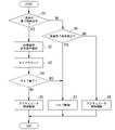
図10を参照し、アクチュエータ保持制御とバルブ保持制御との切り替え制御の一例について説明する。
まず、ステップS1において、ECU60は、車両が登り坂停車中であるか否か(車両が登り坂状況であるか否か)を判定する。例えば、車両が登り坂停車中であるか否かは、IMU検知結果(例えば登り坂の傾斜角度)が閾値以上であるか否かにより判定する。ステップS1でYES(IMU検知結果が閾値以上)の場合(車両が登り坂停車中である場合)、ステップS2に移行する。ステップS1でNO(IMU検知結果が閾値未満)の場合(車両が登り坂停車中ではない場合)、ステップS6に移行する。An example of switching control between actuator hold control and valve hold control will be described with reference to FIG.
First, in step S1, the
ステップS2において、ECU60は、登り坂状況(例えば登り坂の傾斜角度、車両重量、乗員重量、サスペンションの状態など)に応じて半クラッチにより停車位置を維持するために必要な油圧(以下「停車位置必要油圧」ともいう。)を算出する。すなわち、ECU60は、車両が登り坂停車中であることを検知した場合、停車位置必要油圧を算出する。ステップS2の後、ステップS3に移行する。
In step S2, the
ステップS3において、ECU60は、タイマカウントを行う。例えば、ECU60は、ステップS1でYES(車両が登り坂停車中である)と判定されてから停車位置必要油圧算出後の経過時間を計算する。ステップS3の後、ステップS4に移行する。
In step S3, the
ステップS4において、ECU60は、タイマ満了したか否かを判定する。ステップS4でYES(タイマ満了した)の場合、ステップS7に移行する。ステップS4でNO(タイマ満了していない)の場合、ステップS5に移行する。
In step S4, the
ステップS5において、ECU60は、アクチュエータ保持制御を実行する。すなわち、ECU60は、車両が登り坂停車中であることを検知した直後はアクチュエータ保持制御を実行する。
In step S5, the
ステップS7において、ECU60は、バルブ保持制御を実行する(バルブ保持制御を許可する)。すなわち、ECU60は、車両が登り坂停車中であることを検知し、所定時間経過後(例えば数秒以上経過後)にアクチュエータ保持制御からバルブ保持制御に切り替える。言い換えると、ECU60は、クリープ現象を発生させて停車している時間が所定時間よりも長くなった場合、モータ保護および消費電力低減のためにバルブ保持制御に切り替える。
In step S7, the
ステップS6において、ECU60は、発進完了条件成立か否かを判定する。例えば、発進完了条件成立か否かは、後輪車速およびエンジン回転数が所定値以上であるか否かにより判定する。ステップS6でYES(後輪車速およびエンジン回転数が所定値以上)の場合(発進完了条件成立である場合)、ステップS7に移行する。ステップS6でNO(後輪車速およびエンジン回転数が所定値未満)の場合(発進完了条件成立ではない場合)、ステップS8に移行する。
In step S6, the
ステップS7において、ECU60は、バルブ保持制御を実行する。すなわち、ECU60は、車両の発進完了を検知した場合、アクチュエータ保持制御からバルブ保持制御に切り替える。
In step S7, the
ステップS8において、ECU60は、アクチュエータ保持制御を実行する。すなわち、ECU60は、車両の発進完了を検知しない場合(依然として登り坂停車中である場合や車両が発進中である場合)、アクチュエータ保持制御を継続する。
In step S8, the
以上説明したように、上記実施形態の自動二輪車1のクラッチ制御装置60Aは、ノーマルオープンタイプのクラッチ装置26と、クラッチ装置26に油圧を供給するクラッチアクチュエータ50と、クラッチアクチュエータ50とクラッチ装置26とを接続する主油路53m(油路)と、主油路53mに設けられ、主油路53mを連通させる開弁状態と主油路53mを閉鎖する閉弁状態とを切り替え可能なソレノイドバルブ56と、クラッチアクチュエータ50からクラッチ装置26への油圧の供給を許容し、クラッチ装置26からクラッチアクチュエータ50への油圧の供給を遮断するワンウェイバルブ53c1と、クラッチアクチュエータ50の駆動を継続することによりクラッチ装置26に供給される油圧を保持するアクチュエータ保持制御と、クラッチアクチュエータ50の駆動後にソレノイドバルブ56を閉弁状態とすることによりクラッチ装置26に供給される油圧を保持するバルブ保持制御と、を行うECU60と、を備え、ECU60は、アクチュエータ保持制御を維持したまま所定時間経過した場合、アクチュエータ保持制御からバルブ保持制御に切り替える。
この構成によれば、アクチュエータ保持制御を継続する場合と比較して、無駄な油圧の供給を減らすことができる。したがって、消費電力を低減することができる。As described above, the
According to this configuration, it is possible to reduce unnecessary supply of hydraulic pressure compared to the case where the actuator holding control is continued. Therefore, power consumption can be reduced.
上記実施形態では、ECU60は、車両が登り坂状況であることを検知した場合、前記登り坂状況に応じて半クラッチにより停車位置を維持するために必要な油圧を算出することで、以下の効果を奏する。
車両が登り坂状況から発進するときに車両が下がることを抑制することができる。そのため、運転者の技量によらず安定した坂道発進が可能となる。In the above-described embodiment, when the
It is possible to suppress the vehicle from lowering when the vehicle starts from an uphill condition. Therefore, it is possible to stably start the vehicle on a slope regardless of the skill of the driver.
上記実施形態では、車両が前記登り坂状況であることを検知するためのIMU49を更に備え、ECU60は、IMU49の検知結果に基づいて前記停車位置を維持するために必要な油圧を算出することで、以下の効果を奏する。
IMU49の検知結果に基づいた計算により、停車位置を維持するために必要な油圧を正確に算出することができる。In the above embodiment, the vehicle is further provided with the
By calculation based on the detection results of the
<変形例>
上記実施形態では、ECU60は、車両が登り坂状況であることを検知してから所定時間経過後にアクチュエータ保持制御からバルブ保持制御に切り替える例を挙げて説明したが、これに限らない。例えば、ECU60は、車両が登り坂停車以外の車体状況であることを検知してから所定時間経過後にアクチュエータ保持制御からバルブ保持制御に切り替えてもよい。<Modification>
In the above embodiment, an example was given in which the
上記実施形態では、ECU60は、車両が登り坂状況であることを検知した場合、前記登り坂状況に応じて半クラッチにより停車位置を維持するために必要な油圧を算出する例を挙げて説明したが、これに限らない。例えば、ECU60は、車両が登り坂状況であることを検知した場合、前記停車位置を維持するために必要な油圧を算出しなくてもよい。
In the above embodiment, the
上記実施形態では、ECU60は、車両の発進を検知した場合、アクチュエータ保持制御からバルブ保持制御に切り替える例を挙げて説明したが、これに限らない。例えば、ECU60は、車両の発進を検知した後にアクチュエータ保持制御を継続してもよい。
In the above-described embodiment, the
上記実施形態では、車両が前記登り坂状況であることを検知するためのIMU49を更に備える例を挙げて説明したが、これに限らない。例えば、車両はIMU49を備えていなくてもよい。
In the above embodiment, an example in which the vehicle is further provided with the
上記実施形態では、ECU60は、IMU49の検知結果に基づいて停車位置維持必要油圧を算出する例を挙げて説明したが、これに限らない。例えば、ECU60は、IMU49の検知結果以外のパラメータに基づいて停車位置維持必要油圧を算出してもよい。
In the above embodiment, an example was given in which the
なお、本発明は上記実施形態に限られるものではなく、例えば、前記鞍乗り型車両には、運転者が車体を跨いで乗車する車両全般が含まれ、自動二輪車(原動機付自転車及びスクータ型車両を含む)のみならず、三輪(前一輪かつ後二輪の他に、前二輪かつ後一輪の車両も含む)の車両も含まれる。また、本発明は、自動二輪車のみならず、自動車等の四輪の車両にも適用可能である。
そして、上記実施形態における構成は本発明の一例であり、実施形態の構成要素を周知の構成要素に置き換える等、本発明の要旨を逸脱しない範囲で種々の変更が可能である。The present invention is not limited to the above-described embodiments. For example, the saddle type vehicle includes general vehicles in which the driver straddles the vehicle body, motorcycles (motorized bicycles and scooter vehicles). ), but also three-wheeled vehicles (including vehicles with one front wheel and two rear wheels, as well as vehicles with two front wheels and one rear wheel). Moreover, the present invention is applicable not only to motorcycles but also to four-wheeled vehicles such as automobiles.
The configuration in the above embodiment is an example of the present invention, and various modifications, such as replacing the constituent elements of the embodiment with known constituent elements, are possible without departing from the gist of the present invention.
1 自動二輪車(鞍乗り型車両)
26 クラッチ装置
50 クラッチアクチュエータ(アクチュエータ)
53 主油路(油路)
53c1 ワンウェイバルブ
56 ソレノイドバルブ(バルブ機構)
60 ECU(制御部)
60A クラッチ制御装置
49 IMU(慣性計測装置)1 Motorcycle (saddle type vehicle)
26
53 main oil passage (oil passage)
53c1 One-
60 ECU (control unit)
60A
Claims (2)
前記クラッチ装置(26)に油圧を供給するアクチュエータ(50)と、
前記アクチュエータ(50)と前記クラッチ装置(26)とを接続する油路(53m)と、
前記油路(53m)に設けられ、前記油路(53m)を連通させる開弁状態と前記油路(53m)を閉鎖する閉弁状態とを切り替え可能なバルブ機構(56)と、
前記アクチュエータ(50)から前記クラッチ装置(26)への油圧の供給を許容し、前記クラッチ装置(26)から前記アクチュエータ(50)への油圧の供給を遮断するワンウェイバルブ(53c1)と、
前記アクチュエータ(50)の駆動を継続することにより前記クラッチ装置(26)に供給される油圧を保持するアクチュエータ保持制御と、前記アクチュエータ(50)の駆動後に前記バルブ機構(56)を閉弁状態とすることにより前記クラッチ装置(26)に供給される油圧を保持するバルブ保持制御と、を行う制御部(60)と、を備え、
前記制御部(60)は、車両(1)の停止時には、前記アクチュエータ(50)及び前記バルブ機構(56)への電力供給をともに停止するものであって、
前記制御部(60)は、前記車両(1)が登り坂状況であることを検知した場合、前記登り坂状況に応じて半クラッチにより停車位置を維持するために必要な油圧を算出し、
前記制御部(60)は、前記車両(1)が登り坂状況であることを検知し、前記アクチュエータ保持制御を維持したまま所定時間経過した場合、前記アクチュエータ保持制御から前記バルブ保持制御に切り替え、
前記制御部(60)は、下流側の油圧が上限保持油圧(HP)まで上昇した場合は前記バルブ機構(56)を開弁状態とし、前記下流側の油圧が下限保持油圧(LP)まで低下した場合は前記バルブ機構(56)を閉弁状態としたままで上流側の油圧を上昇させることを特徴とする鞍乗り型車両のクラッチ制御装置。 a normally open type clutch device (26);
an actuator (50) that supplies hydraulic pressure to the clutch device (26);
an oil passage (53m) connecting the actuator (50) and the clutch device (26);
a valve mechanism (56) provided in the oil passage (53m) and capable of switching between an open state in which the oil passage (53m) is communicated and a closed state in which the oil passage (53m) is closed;
a one-way valve (53c1) that allows hydraulic pressure to be supplied from the actuator (50) to the clutch device (26) and blocks hydraulic pressure to be supplied from the clutch device (26) to the actuator (50);
actuator hold control for holding hydraulic pressure supplied to the clutch device (26) by continuing to drive the actuator (50); and closing the valve mechanism (56) after the actuator (50) is driven. a control unit (60) for performing valve holding control for holding the hydraulic pressure supplied to the clutch device (26) by
When the vehicle (1) stops, the control unit (60) stops power supply to both the actuator (50) and the valve mechanism (56),
When the control unit (60) detects that the vehicle (1) is in an uphill condition, the control unit (60) calculates the hydraulic pressure necessary to maintain the vehicle stop position with a half-clutch according to the uphill condition,
The control unit (60) detects that the vehicle (1) is in an uphill condition, and switches from the actuator hold control to the valve hold control when a predetermined time has elapsed while the actuator hold control is maintained,
The control unit (60) opens the valve mechanism (56) when the downstream hydraulic pressure rises to the upper limit holding hydraulic pressure (HP), and decreases the downstream hydraulic pressure to the lower limit holding hydraulic pressure (LP). A clutch control device for a saddle-ride type vehicle, characterized in that, when the clutch is closed, the hydraulic pressure on the upstream side is increased while the valve mechanism (56) is kept closed.
前記制御部(60)は、前記慣性計測装置(49)の検知結果に基づいて前記停車位置を維持するために必要な油圧を算出することを特徴とする請求項1に記載の鞍乗り型車両のクラッチ制御装置。 further comprising an inertial measurement device (49) for detecting that the vehicle (1) is in the uphill situation;
The straddle-type vehicle according to claim 1 , wherein the control unit (60) calculates the hydraulic pressure required to maintain the vehicle stop position based on the detection result of the inertia measurement device (49). clutch controller.
Applications Claiming Priority (3)
| Application Number | Priority Date | Filing Date | Title |
|---|---|---|---|
| JP2019059880 | 2019-03-27 | ||
| JP2019059880 | 2019-03-27 | ||
| PCT/JP2020/011511 WO2020196045A1 (en) | 2019-03-27 | 2020-03-16 | Clutch control device for saddle-type vehicle |
Publications (2)
| Publication Number | Publication Date |
|---|---|
| JPWO2020196045A1 JPWO2020196045A1 (en) | 2020-10-01 |
| JP7163483B2 true JP7163483B2 (en) | 2022-10-31 |
Family
ID=72609508
Family Applications (1)
| Application Number | Title | Priority Date | Filing Date |
|---|---|---|---|
| JP2021509101A Active JP7163483B2 (en) | 2019-03-27 | 2020-03-16 | Clutch control device for saddle type vehicle |
Country Status (2)
| Country | Link |
|---|---|
| JP (1) | JP7163483B2 (en) |
| WO (1) | WO2020196045A1 (en) |
Citations (2)
| Publication number | Priority date | Publication date | Assignee | Title |
|---|---|---|---|---|
| JP2011064280A (en) | 2009-09-17 | 2011-03-31 | Toyota Motor Corp | Hydraulic control device for friction engaging mechanism |
| JP2017166686A (en) | 2016-03-18 | 2017-09-21 | 本田技研工業株式会社 | Hydraulic system |
Family Cites Families (3)
| Publication number | Priority date | Publication date | Assignee | Title |
|---|---|---|---|---|
| JPS61129329A (en) * | 1984-11-27 | 1986-06-17 | Hino Motors Ltd | Automatic transmission |
| WO2017169324A1 (en) * | 2016-03-29 | 2017-10-05 | 本田技研工業株式会社 | Driving force control device for straddle-type vehicles |
| JP6715151B2 (en) * | 2016-09-29 | 2020-07-01 | 本田技研工業株式会社 | Clutch actuator |
-
2020
- 2020-03-16 JP JP2021509101A patent/JP7163483B2/en active Active
- 2020-03-16 WO PCT/JP2020/011511 patent/WO2020196045A1/en active Application Filing
Patent Citations (2)
| Publication number | Priority date | Publication date | Assignee | Title |
|---|---|---|---|---|
| JP2011064280A (en) | 2009-09-17 | 2011-03-31 | Toyota Motor Corp | Hydraulic control device for friction engaging mechanism |
| JP2017166686A (en) | 2016-03-18 | 2017-09-21 | 本田技研工業株式会社 | Hydraulic system |
Also Published As
| Publication number | Publication date |
|---|---|
| WO2020196045A1 (en) | 2020-10-01 |
| JPWO2020196045A1 (en) | 2020-10-01 |
Similar Documents
| Publication | Publication Date | Title |
|---|---|---|
| JP6792495B2 (en) | Shift control device | |
| JP7064874B2 (en) | Clutch control device and clutch control system | |
| JP6756043B2 (en) | Vehicle shifting system | |
| JP6845948B2 (en) | Transmission | |
| JP7112594B2 (en) | clutch controller | |
| US10760629B2 (en) | Clutch control apparatus | |
| JP7163483B2 (en) | Clutch control device for saddle type vehicle | |
| JP7130847B2 (en) | Clutch control device for saddle type vehicle | |
| JP7059442B2 (en) | Clutch control device and clutch control method for saddle-mounted vehicles | |
| JP7068465B2 (en) | Clutch control device | |
| JP6726810B2 (en) | Clutch control device | |
| JP6722831B2 (en) | Clutch control device | |
| JP6826522B2 (en) | Clutch control device | |
| JP7073579B2 (en) | Clutch control device and clutch control method for saddle-mounted vehicles | |
| JP7149408B2 (en) | Transmission and transmission control method | |
| JP7003288B2 (en) | Clutch control device | |
| WO2020189426A1 (en) | Clutch control device | |
| JP6953633B2 (en) | Clutch control device | |
| WO2020195895A1 (en) | Clutch control device | |
| WO2020195789A1 (en) | Clutch control device | |
| JP6837416B2 (en) | Clutch control device | |
| JPWO2020039757A1 (en) | Clutch control device and hydraulic equipment control device |
Legal Events
| Date | Code | Title | Description |
|---|---|---|---|
| A529 | Written submission of copy of amendment under article 34 pct |
Free format text: JAPANESE INTERMEDIATE CODE: A5211 Effective date: 20210705 |
|
| A621 | Written request for application examination |
Free format text: JAPANESE INTERMEDIATE CODE: A621 Effective date: 20210705 |
|
| A131 | Notification of reasons for refusal |
Free format text: JAPANESE INTERMEDIATE CODE: A131 Effective date: 20220405 |
|
| A521 | Request for written amendment filed |
Free format text: JAPANESE INTERMEDIATE CODE: A523 Effective date: 20220603 |
|
| TRDD | Decision of grant or rejection written | ||
| A01 | Written decision to grant a patent or to grant a registration (utility model) |
Free format text: JAPANESE INTERMEDIATE CODE: A01 Effective date: 20221004 |
|
| A61 | First payment of annual fees (during grant procedure) |
Free format text: JAPANESE INTERMEDIATE CODE: A61 Effective date: 20221019 |
|
| R150 | Certificate of patent or registration of utility model |
Ref document number: 7163483 Country of ref document: JP Free format text: JAPANESE INTERMEDIATE CODE: R150 |