EP1830002A1 - Système de support de rails pour voie ferrée - Google Patents
Système de support de rails pour voie ferrée Download PDFInfo
- Publication number
- EP1830002A1 EP1830002A1 EP06004197A EP06004197A EP1830002A1 EP 1830002 A1 EP1830002 A1 EP 1830002A1 EP 06004197 A EP06004197 A EP 06004197A EP 06004197 A EP06004197 A EP 06004197A EP 1830002 A1 EP1830002 A1 EP 1830002A1
- Authority
- EP
- European Patent Office
- Prior art keywords
- track
- rails
- rail
- element according
- plate
- Prior art date
- Legal status (The legal status is an assumption and is not a legal conclusion. Google has not performed a legal analysis and makes no representation as to the accuracy of the status listed.)
- Granted
Links
Images

Classifications
-
- E—FIXED CONSTRUCTIONS
- E01—CONSTRUCTION OF ROADS, RAILWAYS, OR BRIDGES
- E01B—PERMANENT WAY; PERMANENT-WAY TOOLS; MACHINES FOR MAKING RAILWAYS OF ALL KINDS
- E01B3/00—Transverse or longitudinal sleepers; Other means resting directly on the ballastway for supporting rails
- E01B3/28—Transverse or longitudinal sleepers; Other means resting directly on the ballastway for supporting rails made from concrete or from natural or artificial stone
- E01B3/40—Slabs; Blocks; Pot sleepers; Fastening tie-rods to them
-
- E—FIXED CONSTRUCTIONS
- E01—CONSTRUCTION OF ROADS, RAILWAYS, OR BRIDGES
- E01B—PERMANENT WAY; PERMANENT-WAY TOOLS; MACHINES FOR MAKING RAILWAYS OF ALL KINDS
- E01B1/00—Ballastway; Other means for supporting the sleepers or the track; Drainage of the ballastway
- E01B1/002—Ballastless track, e.g. concrete slab trackway, or with asphalt layers
-
- E—FIXED CONSTRUCTIONS
- E01—CONSTRUCTION OF ROADS, RAILWAYS, OR BRIDGES
- E01B—PERMANENT WAY; PERMANENT-WAY TOOLS; MACHINES FOR MAKING RAILWAYS OF ALL KINDS
- E01B21/00—Track superstructure adapted for tramways in paved streets
- E01B21/02—Special supporting means; Draining of rails
-
- E—FIXED CONSTRUCTIONS
- E01—CONSTRUCTION OF ROADS, RAILWAYS, OR BRIDGES
- E01B—PERMANENT WAY; PERMANENT-WAY TOOLS; MACHINES FOR MAKING RAILWAYS OF ALL KINDS
- E01B9/00—Fastening rails on sleepers, or the like
- E01B9/38—Indirect fastening of rails by using tie-plates or chairs; Fastening of rails on the tie-plates or in the chairs
- E01B9/44—Fastening the rail on the tie-plate
- E01B9/50—Fastening the rail on the tie-plate by keys
- E01B9/52—Fastening the rail on the tie-plate by keys by resilient keys
Definitions
- the invention relates to a track element for the tram area and the like.
- the track element according to the invention can basically be used for different types of rails or tracks, for example also for railway tracks or railroad tracks,
- the adjustment of the rails or the adjustment of the track of the rails usually relatively expensive.
- the tracks produced by the known measures are characterized by a disadvantageous high sound emission both in terms of structure-borne noise and in terms of airborne sound.
- the invention is the technical problem of specifying a track element of the type mentioned, with which the above Disadvantages are avoided and can be laid, adjusted and mounted in particular in a less expensive way.
- the invention teaches a track element for tram rails and the like, - with a prefabricated track plate, with at least two rails attached to the track plate and with fasteners for attaching the rails start the track plate, the prefabricated track plate having at least two parallel receiving channels for the rails, in which the rails are received in their mounted state over at least the major part of their height, each rail being secured to the receiving channel at a plurality of attachment locations spaced apart in the longitudinal direction of the associated receiving channel with the attachment means, wherein each fastening device has at least one spring element acting on the rail foot of the associated rail and wherein this spring element has an upper-side protective cover.
- An inventive track element is thus a construction of a track plate and the rails attached thereto.
- a plurality of track elements according to the invention is arranged one behind the other in the longitudinal direction of the track.
- the track elements according to the invention can be used for different types of rails, in particular for tram rails or railroad tracks.
- the track elements are used in particular where overriding or crossing of the track by other vehicles is necessary, for example at intersections and the like.
- the on the track plate fastened rails can be, for example grooved rails or head rails (Vignole rails).
- a prefabricated track plate is used for a track element.
- a track plate according to the invention is therefore a factory prefabricated finished part.
- the receiving channels for the rails are already provided.
- the rails are expediently fastened or mounted only after the laying of the prefabricated track slabs in the receiving channels.
- the rails are completely or substantially completely received in the receiving channels with respect to their height. Height of a rail means the extension of the rail from the bottom of the rail foot to the highest point of the rail head.
- the rails are received over at least 85%, preferably over at least 90%, and most preferably over at least 95% of their height in the receiving channels of the track plate.
- the rails are taken over more than 95% of their height in the receiving channels.
- Upper protective cover of the spring element means in particular that this protective cover is set up so that when embedding or concreting the rail no embedding material or no concrete reaches the spring element and the spring function of the spring element is protected in this respect.
- the track base plate made of reinforced concrete, preferably made of reinforced concrete or consists essentially of reinforced concrete, preferably substantially made of reinforced concrete.
- a track base plate according to the invention differs significantly from the thresholds known from the prior art for laying.
- the Track plate has on the one hand the already factory provided receiving channels for the rails and is also much longer than thresholds in the longitudinal direction of the track.
- a track support plate has with respect to its longitudinal direction a plurality of attachment points, which are arranged at greater intervals one behind the other.
- the length of the prefabricated track plate is at least 80 cm, preferably at least 100 cm. Conveniently, the length of the track plate is greater than 100 cm, preferably greater than 150 cm.
- the track slabs according to the invention may have a length of up to 800 cm, preferably up to 700 cm and preferably up to 600 cm. Length of the track plate means the extension of the track plate in the longitudinal direction of the receiving channels or the rails.
- the width of a track plate according to the invention is suitably 100 to 600 cm, preferably 120 to 550 cm and preferably 140 to 520 cm.
- the height of the track plate is suitably 25 to 70 cm, preferably 30 to 65 cm and preferably 35 to 60 cm.
- the attachment points in a receiving channel of the track plate have a mutual distance of at least 30 cm, preferably of at least 35 cm.
- the distance between two fastening points in the longitudinal direction of a receiving channel is more than 35 cm, and more preferably more than 40 cm.
- the rails are attached to these attachment points in the receiving channel or expediently at the bottom of the receiving channel.
- the prefabricated track base plate at each attachment point on at least one base plate, in or on the Floor of the respective receiving channel is fixed.
- the prefabricated track blocks already have the fixed base plates.
- a base plate is expediently embedded in the bottom of the associated receiving channel.
- a base plate is present at each attachment point of the receiving channel.
- the rail to be fixed in the receiving channel is fastened to these base plates.
- the prefabricated track base plate has at its attachment points already embedded in the track base plate or embedded concrete dowels. When mounting the rails in the receiving channels corresponding mounting screws can then be screwed into the fixing dowels. It is within the scope of the invention that the fastening screws associated openings are provided in the base plate.
- at least one fixing dowel is embedded or embedded in concrete on an attachment point on each side of the rail to be mounted.
- a rail has an extending in the rail longitudinal direction Elastomerummantelung.
- the elastomer sheathing preferably surrounds the rail foot and expediently, the rail web is formed elastomer sheathed. It is within the scope of the invention that only acted upon by rail vehicles top of the rail head is free of the Elastomerummantelung. Preferably, the entire rail is otherwise provided with the Elastomerummantelung.
- the elastomer is preferably rubber. In principle, however, it is also possible to use another elastomer for the elastomer coating. The aforementioned embodiment with the elastomer sheathing has proven particularly useful, especially with regard to a surprisingly low acoustic emission.
- each fastening device comprises at least one fixing element, wherein the fixing element a Fixing portion for fixing the fixing element to the track plate and a rail has the cross-section holding portion.
- the fixing portion of the fixing element is fastened with at least one fastening screw on the track plate, wherein the fastening screw is then preferably screwed into an anchored in the track plate mounting dowel.
- the holding portion of the fixing element engages over the rail foot by clamping. It is recommended that at least two fixing elements are provided at each attachment point of a receiving channel and that expediently at least one fixing element on each side of the rail. The holding portions of these opposing fixing elements then engage at an attachment point in each case the rail foot on opposite sides of the rail.
- the holding portion of a fixing element has or forms the protective cover for the spring element.
- the holding section or the protective cover presses the spring element onto the rail foot.
- the spring element is set during the fastening of the rail at the attachment point under bias.
- the holding portion or the protective cover of the fixing element is expediently made of steel.
- a receiving space for the spring element is preferably formed in the holding portion of the fixing element. By selecting the height of this receiving space, the bias of the spring element can be adjusted in the assembled state of the fixing element.
- the protective cover covers the spring element in the assembled state on the top and side.
- the receiving space of the holding portion for the spring element is thus formed closed on all sides and only open at the bottom towards the rail foot.
- at least one fixing element is provided on each of the two sides of the rail at an attachment point of a receiving channel. It is also within the scope of the invention that at least one holding section and at least one spring element associated with the holding section is provided on such an attachment point on each side of the rail.
- a very preferred embodiment of the invention is characterized in that the spring element consists of an elastomer.
- the spring element is then an elastomer spring.
- This embodiment has proven particularly useful.
- rubber or rubber rubber is used as the elastomer. In principle, however, it is also possible to use another elastomeric material for the spring element.
- an adjustment slot is provided in the fixing section of a fixing element, which is penetrated in the mounted state by a fastening element or by a fastening screw. It is within the scope of the invention that it is an oblique slot whose longitudinal axis forms an angle of 5 ° to 30 ° with the longitudinal axis of the receiving channel. Appropriately, such a slot is provided in each of the two fixing elements on the two opposite sides of the rail at an attachment point. With the help of slots, the track width of the rails or the track can be adjusted very effectively and precisely.
- the invention is based on the finding that with the track elements according to the invention a very fast installation, adjustment and installation of tracks is possible. Therefore, the creation of tracks with the track elements according to the invention by a small effort and thus also by a low cost. Due to the short creation times, the areas in which the track is to be created are advantageously blocked only briefly for the rest of traffic.
- the track elements according to the invention are outstandingly suitable for areas in which the track to be created is to be crossed by other vehicles, that is to say in particular for road intersections and the like.
- the track areas produced with the track elements according to the invention are characterized by a very uniform and even surface and thus provide an optimum surface for crossing areas available. Undesirable settlements can be effectively avoided in the track areas provided with the track elements according to the invention.
- the track elements of the invention also allow a very reliable and precise attachment of the rails and a secure and uniform embedding of the rails in the finished track element. With the track elements according to the invention a very precise adjustment of the track is possible and in particular the track of the rails can be easily adjusted or adjusted.
- the track elements according to the invention are further characterized in operation by a surprisingly low noise. The inventive design of the track elements can be significantly reduced when driving both the structure-borne noise and the airborne sound.
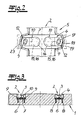
- FIG. 1 The figures show an inventive track element for tram rails and the like.
- a track element initially has a prefabricated track base plate 1, which can be delivered and laid as a finished part.
- This prefabricated track base plate 1 is suitably made of reinforced concrete, preferably made of reinforced concrete.
- it already has prefabricated parallel receiving channels 2 for the rails 3 at the factory.
- the rails 3 are preferably first adjusted and fastened on site in the receiving channels 2 of the track base plate 1, namely with fastening devices 4.
- the rails 3 are accommodated virtually over their entire height h in the receiving channels 2 of the track base plate 1 (see in particular FIG.
- the rails can protrude slightly above from the receiving channel 2.
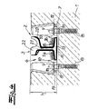
- Each rail 3 is attached to a plurality of in the longitudinal direction of the associated receiving channel 2 spaced attachment points 5 with the fasteners 4 in the receiving channel 2 and that expediently attached to the bottom 6 of the receiving channel 2.
- the distance between two attachment points 5 is preferably and in the embodiment greater than 25cm
- the track support plate 1 used as a finished part already has the cast-in base plates 7.
- the rails 3 are mounted on these base plates 7.
- two fastening dowels 8 are provided at each attachment point 5, namely one attachment dowel 8 on each side of the rail 3 to be fastened.
- these attachment dowels 8 are embedded in the prefabricated track base plate 1.
- the track carrier plate 1 used as a finished part already has the fastening anchors 8 embedded in the concrete.
- Each fixing dowel 8 is assigned a fastening screw 9 for fastening the rail 3.
- a fastening screw 9 in the mounted state passes through an opening of a fixing element 10 and an opening 11 in the base plate 7.
- Each fastening device 4 for the rails 3 has in the exemplary embodiment, in addition to the base plate 7, the fastening dowels 8 and the fastening screws 9 at least two fixing elements 10.
- two fixation elements 10 are provided at each attachment point and that in each case a fixing element 10 on each side of the rail to be fastened 3.
- a fixing element 10 has a fixing portion 12 in which the opening is located, which passes through the fastening screw 9 in the mounted state ,
- the fixing element 10 further comprises a rail section 13 cross-holding portion 14. In the assembled state, ie when tightened fastening screw 9, this holding portion 14 covers the rail 13 clamped.
- the rail 3 is fixed with the fixing elements 10 and with their adhesive portions 14.
- each fixing element 10 or each holding section 14 of the fixing element 10 has a receiving space 15 for a spring element 16.
- the spring element 16 is pressed in the mounted state of the fixing element 10 of the holding portion 14 against the rail 13. As a result, the spring element 16 is set under pretension. Due to the height of the receiving space 15 in the holding portion 14, the bias of the spring element 16 can be adjusted specifically.
- the spring element 16 is according to a very preferred embodiment of the invention and in the exemplary embodiment is an elastomeric element or an elastomeric spring.
- the elastomer spring is as well as the receiving space 15 of the holding portion 14 in the embodiment cylindrical in shape.
- the holding portion 14 forms as it were a protective cover for the spring element 16 and for the elastomer spring.
- the holding section 14 protects the elastomer spring from penetrating embedding material or from penetrating concrete. Also, otherwise, the holding portion 14 forms an effective protective cover and ensures long-term resilient action of the spring element 16. In the embodiment covers the holding portion 14, the spring element 16 on the top and side, so that the receiving space 15 is opened only down to the rail 13.
- the opening provided in the fixing section 12 of the fixing element 10 for the fastening screw 9 is designed as a slot 17.
- the longitudinal axis of the elongated hole 17 is preferably arranged obliquely to the longitudinal axis of the receiving channel 2.
- the Longitudinal axis of the elongated hole 17 forms advantageously with the longitudinal axis of the receiving channel 2 and with the longitudinal axis of the rail 3 to be fastened an angle of 5 ° to 30 °, preferably an angle of 10 ° to 20 °.
- the two opposite at an attachment point 5 slots 17 allow for used, but not yet fully tightened mounting screws 9 a displacement of the fixing elements 10 in the direction of the longitudinal axes of the slots 17.
- the outer edge 18 of the fixing elements 10 is also preferably also formed obliquely and preferably parallel to the longitudinal axis of the associated elongated hole 17. This outer edge 18 is conveniently located on a likewise parallel to the longitudinal axis of the associated slot 17 arranged inclined stop 19.
- the fixing element 10 can then be displaced functionally against the oblique stop 19 during a displacement in the direction of the longitudinal axis of the elongated hole 17 with its outer edge 18.
- the oblique stop 19 may be part of the cast-in base plate 7 by this oblique stopper 19 projects from the surface of the base plate upwards. However, the oblique stop 19 may also be formed by the material or by the concrete of the prefabricated track base plate. Then the oblique stops 19 are already part of a used as a finished track support plate. 1
- the rails 3 have an elastomer casing 20 extending in the rail longitudinal direction.
- the elastomer sheathing 20 is expediently provided continuously in the longitudinal direction of a rail 3 or provided substantially continuously.
- the rail foot 13, the rail web 21 and the underside of the rail head 22 are provided with the elastomer sheathing 20.
- the embodiment with the elastomer sheathing 20 has proven particularly useful in the context of the invention, specifically in combination with the spring element 16 or with the spring element 16 designed as an elastomeric spring.
- the elastomer sheathing 20 is preferably made of rubber rubber.
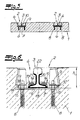
- the receiving channels 2 have lateral widenings 23 at the attachment points 5.
- a receiving channel 2 at the attachment points 5 expediently wider than in its other areas.
- the receiving channels 2 preferably have a trapezoidal cross-section, wherein the width of a receiving channel 2 tapers from the bottom 6 upwards.
- the rails 3 are mounted in the receiving channels 2 at the attachment points 5, then the receiving channels 2 are then suitably filled with an embedding material, for example, filled with concrete.
- an embedding material for example, filled with concrete.
- 5 and 6 head rails are used as rails 3 in the embodiment according to FIGS. Both types of rails are well suited for the track elements according to the invention.
Landscapes
- Engineering & Computer Science (AREA)
- Architecture (AREA)
- Civil Engineering (AREA)
- Structural Engineering (AREA)
- Mechanical Engineering (AREA)
- Road Paving Structures (AREA)
- Electrical Discharge Machining, Electrochemical Machining, And Combined Machining (AREA)
- Machines For Laying And Maintaining Railways (AREA)
- Train Traffic Observation, Control, And Security (AREA)
- Connection Of Plates (AREA)
- Bearings For Parts Moving Linearly (AREA)
Priority Applications (3)
| Application Number | Priority Date | Filing Date | Title |
|---|---|---|---|
| EP06004197A EP1830002B1 (fr) | 2006-03-02 | 2006-03-02 | Système de support de rails pour voie ferrée |
| DE502006007022T DE502006007022D1 (de) | 2006-03-02 | 2006-03-02 | Gleiselement für Straßenbahnschienen und dergleichen |
| AT06004197T ATE469269T1 (de) | 2006-03-02 | 2006-03-02 | GLEISELEMENT FÜR STRAßENBAHNSCHIENEN UND DERGLEICHEN |
Applications Claiming Priority (1)
| Application Number | Priority Date | Filing Date | Title |
|---|---|---|---|
| EP06004197A EP1830002B1 (fr) | 2006-03-02 | 2006-03-02 | Système de support de rails pour voie ferrée |
Publications (2)
| Publication Number | Publication Date |
|---|---|
| EP1830002A1 true EP1830002A1 (fr) | 2007-09-05 |
| EP1830002B1 EP1830002B1 (fr) | 2010-05-26 |
Family
ID=36613402
Family Applications (1)
| Application Number | Title | Priority Date | Filing Date |
|---|---|---|---|
| EP06004197A Not-in-force EP1830002B1 (fr) | 2006-03-02 | 2006-03-02 | Système de support de rails pour voie ferrée |
Country Status (3)
| Country | Link |
|---|---|
| EP (1) | EP1830002B1 (fr) |
| AT (1) | ATE469269T1 (fr) |
| DE (1) | DE502006007022D1 (fr) |
Cited By (1)
| Publication number | Priority date | Publication date | Assignee | Title |
|---|---|---|---|---|
| DE102010009619A1 (de) | 2010-03-01 | 2011-09-01 | Phoenix Dichtungstechnik Gmbh | Profil zur elastischen Lagerung von Schienen |
Citations (6)
| Publication number | Priority date | Publication date | Assignee | Title |
|---|---|---|---|---|
| DE4007937A1 (de) * | 1990-03-13 | 1991-09-19 | Krupp Lonrho Gmbh | Elastisch gelagerte schiene fuer schienenfahrzeuge |
| DE4212679A1 (de) * | 1992-04-15 | 1993-10-21 | Butzbacher Weichenbau Gmbh | Anordnung einer Schiene |
| EP0794290A1 (fr) * | 1996-03-07 | 1997-09-10 | Fried. Krupp AG Hoesch-Krupp | Dispositif de fixation élastique et régable latéralement pour un rail |
| EP1264932A2 (fr) * | 2001-06-08 | 2002-12-11 | Matthias Müller | Fixation d'un rail |
| EP1279770A2 (fr) * | 2001-07-25 | 2003-01-29 | Patrick Vanhonacker | Système de support de rails pour voie ferrée |
| WO2004033795A1 (fr) * | 2002-10-08 | 2004-04-22 | Hyperlast Limited | Chemisage de rails |
-
2006
- 2006-03-02 AT AT06004197T patent/ATE469269T1/de active
- 2006-03-02 DE DE502006007022T patent/DE502006007022D1/de active Active
- 2006-03-02 EP EP06004197A patent/EP1830002B1/fr not_active Not-in-force
Patent Citations (6)
| Publication number | Priority date | Publication date | Assignee | Title |
|---|---|---|---|---|
| DE4007937A1 (de) * | 1990-03-13 | 1991-09-19 | Krupp Lonrho Gmbh | Elastisch gelagerte schiene fuer schienenfahrzeuge |
| DE4212679A1 (de) * | 1992-04-15 | 1993-10-21 | Butzbacher Weichenbau Gmbh | Anordnung einer Schiene |
| EP0794290A1 (fr) * | 1996-03-07 | 1997-09-10 | Fried. Krupp AG Hoesch-Krupp | Dispositif de fixation élastique et régable latéralement pour un rail |
| EP1264932A2 (fr) * | 2001-06-08 | 2002-12-11 | Matthias Müller | Fixation d'un rail |
| EP1279770A2 (fr) * | 2001-07-25 | 2003-01-29 | Patrick Vanhonacker | Système de support de rails pour voie ferrée |
| WO2004033795A1 (fr) * | 2002-10-08 | 2004-04-22 | Hyperlast Limited | Chemisage de rails |
Cited By (2)
| Publication number | Priority date | Publication date | Assignee | Title |
|---|---|---|---|---|
| DE102010009619A1 (de) | 2010-03-01 | 2011-09-01 | Phoenix Dichtungstechnik Gmbh | Profil zur elastischen Lagerung von Schienen |
| EP2363530A1 (fr) | 2010-03-01 | 2011-09-07 | voestalpine Klöckner Bahntechnik GmbH | Profilé de support élastique de rails |
Also Published As
| Publication number | Publication date |
|---|---|
| DE502006007022D1 (de) | 2010-07-08 |
| ATE469269T1 (de) | 2010-06-15 |
| EP1830002B1 (fr) | 2010-05-26 |
Similar Documents
| Publication | Publication Date | Title |
|---|---|---|
| EP2229479B1 (fr) | Appui pour un système de fixation d'un rail et système de fixation d'un rail | |
| EP2318589B1 (fr) | Dispositif pour fixer des rails de chemin de fer sur une sous-structure | |
| DE202006020567U1 (de) | System zur Befestigung einer Schiene | |
| EP0937181B1 (fr) | Fondation de voie ferree | |
| DE10138803A1 (de) | Verfahren zum kontinuierlichen Lagern einer Schiene auf einer festen Fahrbahn sowie Justiereinrichtung und feste Fahrbahn | |
| EP3437954B1 (fr) | Dispositif de protection | |
| EP3597825A1 (fr) | Système de fixation de rail | |
| EP0432357A1 (fr) | Dispositif pour appliquer des rails pour des véhicules à rail | |
| DE102007044098B3 (de) | System zum Befestigen einer Schiene auf einem festen Untergrund | |
| DE4328185C1 (de) | Brückenbalken mit einer Befestigung an Träger einer Stahl-Eisenbahnbrücke | |
| EP1830002B1 (fr) | Système de support de rails pour voie ferrée | |
| DE102011003216A1 (de) | Befestigung für Schienen auf entlang eines Schienenweges verlegten Schwellen | |
| EP0853706B1 (fr) | Passage a niveau | |
| EP0952252B1 (fr) | Coffrage pour l'encastrement d'un rail | |
| AT411694B (de) | Einrichtung zur elastischen lagerung einer rillenschiene | |
| DE10157676A1 (de) | Einrichtung zum seitlichen Abstützen einer Schiene | |
| EP2800833B1 (fr) | Voie ferrée sans ballast | |
| DE850457C (de) | UEberwegbefestigung aus bewehrten Betonplatten fuer Gleisanlagen | |
| DE102008026693A1 (de) | Vorrichtung zum Überbrücken von Dehnungsfugen in Bauwerksteilen | |
| DE102020113136A1 (de) | Verschiebeschutzvorrichtung für Flächenbelagelemente und Flächenbelagelement mit einer solchen Verschiebeschutzvorrichtung | |
| DE19920075A1 (de) | Lagerung einer Schiene für Schienenfahrzeuge | |
| DE4325869C2 (de) | Feste Fahrbahn für schienengebundenen Verkehr | |
| AT375699B (de) | Schienenanordnung, insbesondere fuer strassenbahn- gleise | |
| DE102004050175B3 (de) | Befestigungsvorrichtung für Schienen | |
| EP1264932A2 (fr) | Fixation d'un rail |
Legal Events
| Date | Code | Title | Description |
|---|---|---|---|
| PUAI | Public reference made under article 153(3) epc to a published international application that has entered the european phase |
Free format text: ORIGINAL CODE: 0009012 |
|
| AK | Designated contracting states |
Kind code of ref document: A1 Designated state(s): AT BE BG CH CY CZ DE DK EE ES FI FR GB GR HU IE IS IT LI LT LU LV MC NL PL PT RO SE SI SK TR |
|
| AX | Request for extension of the european patent |
Extension state: AL BA HR MK YU |
|
| 17P | Request for examination filed |
Effective date: 20070921 |
|
| AKX | Designation fees paid |
Designated state(s): AT BE BG CH CY CZ DE DK EE ES FI FR GB GR HU IE IS IT LI LT LU LV MC NL PL PT RO SE SI SK TR |
|
| GRAP | Despatch of communication of intention to grant a patent |
Free format text: ORIGINAL CODE: EPIDOSNIGR1 |
|
| GRAS | Grant fee paid |
Free format text: ORIGINAL CODE: EPIDOSNIGR3 |
|
| GRAA | (expected) grant |
Free format text: ORIGINAL CODE: 0009210 |
|
| AK | Designated contracting states |
Kind code of ref document: B1 Designated state(s): AT BE BG CH CY CZ DE DK EE ES FI FR GB GR HU IE IS IT LI LT LU LV MC NL PL PT RO SE SI SK TR |
|
| REG | Reference to a national code |
Ref country code: GB Ref legal event code: FG4D Free format text: NOT ENGLISH |
|
| REG | Reference to a national code |
Ref country code: CH Ref legal event code: EP |
|
| REG | Reference to a national code |
Ref country code: IE Ref legal event code: FG4D Free format text: LANGUAGE OF EP DOCUMENT: GERMAN |
|
| REF | Corresponds to: |
Ref document number: 502006007022 Country of ref document: DE Date of ref document: 20100708 Kind code of ref document: P |
|
| REG | Reference to a national code |
Ref country code: NL Ref legal event code: VDEP Effective date: 20100526 |
|
| LTIE | Lt: invalidation of european patent or patent extension |
Effective date: 20100526 |
|
| PG25 | Lapsed in a contracting state [announced via postgrant information from national office to epo] |
Ref country code: LT Free format text: LAPSE BECAUSE OF FAILURE TO SUBMIT A TRANSLATION OF THE DESCRIPTION OR TO PAY THE FEE WITHIN THE PRESCRIBED TIME-LIMIT Effective date: 20100526 Ref country code: SE Free format text: LAPSE BECAUSE OF FAILURE TO SUBMIT A TRANSLATION OF THE DESCRIPTION OR TO PAY THE FEE WITHIN THE PRESCRIBED TIME-LIMIT Effective date: 20100526 |
|
| PG25 | Lapsed in a contracting state [announced via postgrant information from national office to epo] |
Ref country code: LV Free format text: LAPSE BECAUSE OF FAILURE TO SUBMIT A TRANSLATION OF THE DESCRIPTION OR TO PAY THE FEE WITHIN THE PRESCRIBED TIME-LIMIT Effective date: 20100526 Ref country code: SI Free format text: LAPSE BECAUSE OF FAILURE TO SUBMIT A TRANSLATION OF THE DESCRIPTION OR TO PAY THE FEE WITHIN THE PRESCRIBED TIME-LIMIT Effective date: 20100526 Ref country code: FI Free format text: LAPSE BECAUSE OF FAILURE TO SUBMIT A TRANSLATION OF THE DESCRIPTION OR TO PAY THE FEE WITHIN THE PRESCRIBED TIME-LIMIT Effective date: 20100526 Ref country code: IS Free format text: LAPSE BECAUSE OF FAILURE TO SUBMIT A TRANSLATION OF THE DESCRIPTION OR TO PAY THE FEE WITHIN THE PRESCRIBED TIME-LIMIT Effective date: 20100926 |
|
| PG25 | Lapsed in a contracting state [announced via postgrant information from national office to epo] |
Ref country code: PL Free format text: LAPSE BECAUSE OF FAILURE TO SUBMIT A TRANSLATION OF THE DESCRIPTION OR TO PAY THE FEE WITHIN THE PRESCRIBED TIME-LIMIT Effective date: 20100526 Ref country code: CY Free format text: LAPSE BECAUSE OF FAILURE TO SUBMIT A TRANSLATION OF THE DESCRIPTION OR TO PAY THE FEE WITHIN THE PRESCRIBED TIME-LIMIT Effective date: 20100526 |
|
| REG | Reference to a national code |
Ref country code: IE Ref legal event code: FD4D |
|
| PG25 | Lapsed in a contracting state [announced via postgrant information from national office to epo] |
Ref country code: PT Free format text: LAPSE BECAUSE OF FAILURE TO SUBMIT A TRANSLATION OF THE DESCRIPTION OR TO PAY THE FEE WITHIN THE PRESCRIBED TIME-LIMIT Effective date: 20100927 Ref country code: EE Free format text: LAPSE BECAUSE OF FAILURE TO SUBMIT A TRANSLATION OF THE DESCRIPTION OR TO PAY THE FEE WITHIN THE PRESCRIBED TIME-LIMIT Effective date: 20100526 Ref country code: DK Free format text: LAPSE BECAUSE OF FAILURE TO SUBMIT A TRANSLATION OF THE DESCRIPTION OR TO PAY THE FEE WITHIN THE PRESCRIBED TIME-LIMIT Effective date: 20100526 Ref country code: NL Free format text: LAPSE BECAUSE OF FAILURE TO SUBMIT A TRANSLATION OF THE DESCRIPTION OR TO PAY THE FEE WITHIN THE PRESCRIBED TIME-LIMIT Effective date: 20100526 Ref country code: IE Free format text: LAPSE BECAUSE OF FAILURE TO SUBMIT A TRANSLATION OF THE DESCRIPTION OR TO PAY THE FEE WITHIN THE PRESCRIBED TIME-LIMIT Effective date: 20100526 |
|
| PG25 | Lapsed in a contracting state [announced via postgrant information from national office to epo] |
Ref country code: SK Free format text: LAPSE BECAUSE OF FAILURE TO SUBMIT A TRANSLATION OF THE DESCRIPTION OR TO PAY THE FEE WITHIN THE PRESCRIBED TIME-LIMIT Effective date: 20100526 Ref country code: RO Free format text: LAPSE BECAUSE OF FAILURE TO SUBMIT A TRANSLATION OF THE DESCRIPTION OR TO PAY THE FEE WITHIN THE PRESCRIBED TIME-LIMIT Effective date: 20100526 Ref country code: CZ Free format text: LAPSE BECAUSE OF FAILURE TO SUBMIT A TRANSLATION OF THE DESCRIPTION OR TO PAY THE FEE WITHIN THE PRESCRIBED TIME-LIMIT Effective date: 20100526 |
|
| PG25 | Lapsed in a contracting state [announced via postgrant information from national office to epo] |
Ref country code: IT Free format text: LAPSE BECAUSE OF FAILURE TO SUBMIT A TRANSLATION OF THE DESCRIPTION OR TO PAY THE FEE WITHIN THE PRESCRIBED TIME-LIMIT Effective date: 20100526 |
|
| PLBE | No opposition filed within time limit |
Free format text: ORIGINAL CODE: 0009261 |
|
| STAA | Information on the status of an ep patent application or granted ep patent |
Free format text: STATUS: NO OPPOSITION FILED WITHIN TIME LIMIT |
|
| 26N | No opposition filed |
Effective date: 20110301 |
|
| REG | Reference to a national code |
Ref country code: DE Ref legal event code: R097 Ref document number: 502006007022 Country of ref document: DE Effective date: 20110228 |
|
| BERE | Be: lapsed |
Owner name: BTE STELCON DEUTSCHLAND G.M.B.H. Effective date: 20110331 Owner name: VOESTALPINE KLOCKNER BAHNTECHNIK G.M.B.H. Effective date: 20110331 |
|
| PG25 | Lapsed in a contracting state [announced via postgrant information from national office to epo] |
Ref country code: MC Free format text: LAPSE BECAUSE OF NON-PAYMENT OF DUE FEES Effective date: 20110331 |
|
| REG | Reference to a national code |
Ref country code: CH Ref legal event code: PL |
|
| GBPC | Gb: european patent ceased through non-payment of renewal fee |
Effective date: 20110302 |
|
| REG | Reference to a national code |
Ref country code: FR Ref legal event code: ST Effective date: 20111130 |
|
| PG25 | Lapsed in a contracting state [announced via postgrant information from national office to epo] |
Ref country code: BE Free format text: LAPSE BECAUSE OF NON-PAYMENT OF DUE FEES Effective date: 20110331 |
|
| PG25 | Lapsed in a contracting state [announced via postgrant information from national office to epo] |
Ref country code: CH Free format text: LAPSE BECAUSE OF NON-PAYMENT OF DUE FEES Effective date: 20110331 Ref country code: FR Free format text: LAPSE BECAUSE OF NON-PAYMENT OF DUE FEES Effective date: 20110331 Ref country code: LI Free format text: LAPSE BECAUSE OF NON-PAYMENT OF DUE FEES Effective date: 20110331 |
|
| PG25 | Lapsed in a contracting state [announced via postgrant information from national office to epo] |
Ref country code: GB Free format text: LAPSE BECAUSE OF NON-PAYMENT OF DUE FEES Effective date: 20110302 |
|
| REG | Reference to a national code |
Ref country code: AT Ref legal event code: MM01 Ref document number: 469269 Country of ref document: AT Kind code of ref document: T Effective date: 20110302 |
|
| PG25 | Lapsed in a contracting state [announced via postgrant information from national office to epo] |
Ref country code: AT Free format text: LAPSE BECAUSE OF NON-PAYMENT OF DUE FEES Effective date: 20110302 |
|
| PG25 | Lapsed in a contracting state [announced via postgrant information from national office to epo] |
Ref country code: LU Free format text: LAPSE BECAUSE OF NON-PAYMENT OF DUE FEES Effective date: 20110302 |
|
| PG25 | Lapsed in a contracting state [announced via postgrant information from national office to epo] |
Ref country code: BG Free format text: LAPSE BECAUSE OF FAILURE TO SUBMIT A TRANSLATION OF THE DESCRIPTION OR TO PAY THE FEE WITHIN THE PRESCRIBED TIME-LIMIT Effective date: 20100826 Ref country code: TR Free format text: LAPSE BECAUSE OF FAILURE TO SUBMIT A TRANSLATION OF THE DESCRIPTION OR TO PAY THE FEE WITHIN THE PRESCRIBED TIME-LIMIT Effective date: 20100526 |
|
| PG25 | Lapsed in a contracting state [announced via postgrant information from national office to epo] |
Ref country code: ES Free format text: LAPSE BECAUSE OF FAILURE TO SUBMIT A TRANSLATION OF THE DESCRIPTION OR TO PAY THE FEE WITHIN THE PRESCRIBED TIME-LIMIT Effective date: 20100906 Ref country code: HU Free format text: LAPSE BECAUSE OF FAILURE TO SUBMIT A TRANSLATION OF THE DESCRIPTION OR TO PAY THE FEE WITHIN THE PRESCRIBED TIME-LIMIT Effective date: 20100526 |
|
| PG25 | Lapsed in a contracting state [announced via postgrant information from national office to epo] |
Ref country code: GR Free format text: LAPSE BECAUSE OF FAILURE TO SUBMIT A TRANSLATION OF THE DESCRIPTION OR TO PAY THE FEE WITHIN THE PRESCRIBED TIME-LIMIT Effective date: 20100526 |
|
| PGFP | Annual fee paid to national office [announced via postgrant information from national office to epo] |
Ref country code: DE Payment date: 20170403 Year of fee payment: 12 |
|
| REG | Reference to a national code |
Ref country code: DE Ref legal event code: R119 Ref document number: 502006007022 Country of ref document: DE |
|
| PG25 | Lapsed in a contracting state [announced via postgrant information from national office to epo] |
Ref country code: DE Free format text: LAPSE BECAUSE OF NON-PAYMENT OF DUE FEES Effective date: 20181002 |