EP1830002A1 - Track structure adapted for tramways - Google Patents
Track structure adapted for tramways Download PDFInfo
- Publication number
- EP1830002A1 EP1830002A1 EP06004197A EP06004197A EP1830002A1 EP 1830002 A1 EP1830002 A1 EP 1830002A1 EP 06004197 A EP06004197 A EP 06004197A EP 06004197 A EP06004197 A EP 06004197A EP 1830002 A1 EP1830002 A1 EP 1830002A1
- Authority
- EP
- European Patent Office
- Prior art keywords
- track
- rails
- rail
- element according
- plate
- Prior art date
- Legal status (The legal status is an assumption and is not a legal conclusion. Google has not performed a legal analysis and makes no representation as to the accuracy of the status listed.)
- Granted
Links
Images

Classifications
-
- E—FIXED CONSTRUCTIONS
- E01—CONSTRUCTION OF ROADS, RAILWAYS, OR BRIDGES
- E01B—PERMANENT WAY; PERMANENT-WAY TOOLS; MACHINES FOR MAKING RAILWAYS OF ALL KINDS
- E01B3/00—Transverse or longitudinal sleepers; Other means resting directly on the ballastway for supporting rails
- E01B3/28—Transverse or longitudinal sleepers; Other means resting directly on the ballastway for supporting rails made from concrete or from natural or artificial stone
- E01B3/40—Slabs; Blocks; Pot sleepers; Fastening tie-rods to them
-
- E—FIXED CONSTRUCTIONS
- E01—CONSTRUCTION OF ROADS, RAILWAYS, OR BRIDGES
- E01B—PERMANENT WAY; PERMANENT-WAY TOOLS; MACHINES FOR MAKING RAILWAYS OF ALL KINDS
- E01B1/00—Ballastway; Other means for supporting the sleepers or the track; Drainage of the ballastway
- E01B1/002—Ballastless track, e.g. concrete slab trackway, or with asphalt layers
-
- E—FIXED CONSTRUCTIONS
- E01—CONSTRUCTION OF ROADS, RAILWAYS, OR BRIDGES
- E01B—PERMANENT WAY; PERMANENT-WAY TOOLS; MACHINES FOR MAKING RAILWAYS OF ALL KINDS
- E01B21/00—Track superstructure adapted for tramways in paved streets
- E01B21/02—Special supporting means; Draining of rails
-
- E—FIXED CONSTRUCTIONS
- E01—CONSTRUCTION OF ROADS, RAILWAYS, OR BRIDGES
- E01B—PERMANENT WAY; PERMANENT-WAY TOOLS; MACHINES FOR MAKING RAILWAYS OF ALL KINDS
- E01B9/00—Fastening rails on sleepers, or the like
- E01B9/38—Indirect fastening of rails by using tie-plates or chairs; Fastening of rails on the tie-plates or in the chairs
- E01B9/44—Fastening the rail on the tie-plate
- E01B9/50—Fastening the rail on the tie-plate by keys
- E01B9/52—Fastening the rail on the tie-plate by keys by resilient keys
Definitions
- the invention relates to a track element for the tram area and the like.
- the track element according to the invention can basically be used for different types of rails or tracks, for example also for railway tracks or railroad tracks,
- the adjustment of the rails or the adjustment of the track of the rails usually relatively expensive.
- the tracks produced by the known measures are characterized by a disadvantageous high sound emission both in terms of structure-borne noise and in terms of airborne sound.
- the invention is the technical problem of specifying a track element of the type mentioned, with which the above Disadvantages are avoided and can be laid, adjusted and mounted in particular in a less expensive way.
- the invention teaches a track element for tram rails and the like, - with a prefabricated track plate, with at least two rails attached to the track plate and with fasteners for attaching the rails start the track plate, the prefabricated track plate having at least two parallel receiving channels for the rails, in which the rails are received in their mounted state over at least the major part of their height, each rail being secured to the receiving channel at a plurality of attachment locations spaced apart in the longitudinal direction of the associated receiving channel with the attachment means, wherein each fastening device has at least one spring element acting on the rail foot of the associated rail and wherein this spring element has an upper-side protective cover.
- An inventive track element is thus a construction of a track plate and the rails attached thereto.
- a plurality of track elements according to the invention is arranged one behind the other in the longitudinal direction of the track.
- the track elements according to the invention can be used for different types of rails, in particular for tram rails or railroad tracks.
- the track elements are used in particular where overriding or crossing of the track by other vehicles is necessary, for example at intersections and the like.
- the on the track plate fastened rails can be, for example grooved rails or head rails (Vignole rails).
- a prefabricated track plate is used for a track element.
- a track plate according to the invention is therefore a factory prefabricated finished part.
- the receiving channels for the rails are already provided.
- the rails are expediently fastened or mounted only after the laying of the prefabricated track slabs in the receiving channels.
- the rails are completely or substantially completely received in the receiving channels with respect to their height. Height of a rail means the extension of the rail from the bottom of the rail foot to the highest point of the rail head.
- the rails are received over at least 85%, preferably over at least 90%, and most preferably over at least 95% of their height in the receiving channels of the track plate.
- the rails are taken over more than 95% of their height in the receiving channels.
- Upper protective cover of the spring element means in particular that this protective cover is set up so that when embedding or concreting the rail no embedding material or no concrete reaches the spring element and the spring function of the spring element is protected in this respect.
- the track base plate made of reinforced concrete, preferably made of reinforced concrete or consists essentially of reinforced concrete, preferably substantially made of reinforced concrete.
- a track base plate according to the invention differs significantly from the thresholds known from the prior art for laying.
- the Track plate has on the one hand the already factory provided receiving channels for the rails and is also much longer than thresholds in the longitudinal direction of the track.
- a track support plate has with respect to its longitudinal direction a plurality of attachment points, which are arranged at greater intervals one behind the other.
- the length of the prefabricated track plate is at least 80 cm, preferably at least 100 cm. Conveniently, the length of the track plate is greater than 100 cm, preferably greater than 150 cm.
- the track slabs according to the invention may have a length of up to 800 cm, preferably up to 700 cm and preferably up to 600 cm. Length of the track plate means the extension of the track plate in the longitudinal direction of the receiving channels or the rails.
- the width of a track plate according to the invention is suitably 100 to 600 cm, preferably 120 to 550 cm and preferably 140 to 520 cm.
- the height of the track plate is suitably 25 to 70 cm, preferably 30 to 65 cm and preferably 35 to 60 cm.
- the attachment points in a receiving channel of the track plate have a mutual distance of at least 30 cm, preferably of at least 35 cm.
- the distance between two fastening points in the longitudinal direction of a receiving channel is more than 35 cm, and more preferably more than 40 cm.
- the rails are attached to these attachment points in the receiving channel or expediently at the bottom of the receiving channel.
- the prefabricated track base plate at each attachment point on at least one base plate, in or on the Floor of the respective receiving channel is fixed.
- the prefabricated track blocks already have the fixed base plates.
- a base plate is expediently embedded in the bottom of the associated receiving channel.
- a base plate is present at each attachment point of the receiving channel.
- the rail to be fixed in the receiving channel is fastened to these base plates.
- the prefabricated track base plate has at its attachment points already embedded in the track base plate or embedded concrete dowels. When mounting the rails in the receiving channels corresponding mounting screws can then be screwed into the fixing dowels. It is within the scope of the invention that the fastening screws associated openings are provided in the base plate.
- at least one fixing dowel is embedded or embedded in concrete on an attachment point on each side of the rail to be mounted.
- a rail has an extending in the rail longitudinal direction Elastomerummantelung.
- the elastomer sheathing preferably surrounds the rail foot and expediently, the rail web is formed elastomer sheathed. It is within the scope of the invention that only acted upon by rail vehicles top of the rail head is free of the Elastomerummantelung. Preferably, the entire rail is otherwise provided with the Elastomerummantelung.
- the elastomer is preferably rubber. In principle, however, it is also possible to use another elastomer for the elastomer coating. The aforementioned embodiment with the elastomer sheathing has proven particularly useful, especially with regard to a surprisingly low acoustic emission.
- each fastening device comprises at least one fixing element, wherein the fixing element a Fixing portion for fixing the fixing element to the track plate and a rail has the cross-section holding portion.
- the fixing portion of the fixing element is fastened with at least one fastening screw on the track plate, wherein the fastening screw is then preferably screwed into an anchored in the track plate mounting dowel.
- the holding portion of the fixing element engages over the rail foot by clamping. It is recommended that at least two fixing elements are provided at each attachment point of a receiving channel and that expediently at least one fixing element on each side of the rail. The holding portions of these opposing fixing elements then engage at an attachment point in each case the rail foot on opposite sides of the rail.
- the holding portion of a fixing element has or forms the protective cover for the spring element.
- the holding section or the protective cover presses the spring element onto the rail foot.
- the spring element is set during the fastening of the rail at the attachment point under bias.
- the holding portion or the protective cover of the fixing element is expediently made of steel.
- a receiving space for the spring element is preferably formed in the holding portion of the fixing element. By selecting the height of this receiving space, the bias of the spring element can be adjusted in the assembled state of the fixing element.
- the protective cover covers the spring element in the assembled state on the top and side.
- the receiving space of the holding portion for the spring element is thus formed closed on all sides and only open at the bottom towards the rail foot.
- at least one fixing element is provided on each of the two sides of the rail at an attachment point of a receiving channel. It is also within the scope of the invention that at least one holding section and at least one spring element associated with the holding section is provided on such an attachment point on each side of the rail.
- a very preferred embodiment of the invention is characterized in that the spring element consists of an elastomer.
- the spring element is then an elastomer spring.
- This embodiment has proven particularly useful.
- rubber or rubber rubber is used as the elastomer. In principle, however, it is also possible to use another elastomeric material for the spring element.
- an adjustment slot is provided in the fixing section of a fixing element, which is penetrated in the mounted state by a fastening element or by a fastening screw. It is within the scope of the invention that it is an oblique slot whose longitudinal axis forms an angle of 5 ° to 30 ° with the longitudinal axis of the receiving channel. Appropriately, such a slot is provided in each of the two fixing elements on the two opposite sides of the rail at an attachment point. With the help of slots, the track width of the rails or the track can be adjusted very effectively and precisely.
- the invention is based on the finding that with the track elements according to the invention a very fast installation, adjustment and installation of tracks is possible. Therefore, the creation of tracks with the track elements according to the invention by a small effort and thus also by a low cost. Due to the short creation times, the areas in which the track is to be created are advantageously blocked only briefly for the rest of traffic.
- the track elements according to the invention are outstandingly suitable for areas in which the track to be created is to be crossed by other vehicles, that is to say in particular for road intersections and the like.
- the track areas produced with the track elements according to the invention are characterized by a very uniform and even surface and thus provide an optimum surface for crossing areas available. Undesirable settlements can be effectively avoided in the track areas provided with the track elements according to the invention.
- the track elements of the invention also allow a very reliable and precise attachment of the rails and a secure and uniform embedding of the rails in the finished track element. With the track elements according to the invention a very precise adjustment of the track is possible and in particular the track of the rails can be easily adjusted or adjusted.
- the track elements according to the invention are further characterized in operation by a surprisingly low noise. The inventive design of the track elements can be significantly reduced when driving both the structure-borne noise and the airborne sound.
- FIG. 1 The figures show an inventive track element for tram rails and the like.
- a track element initially has a prefabricated track base plate 1, which can be delivered and laid as a finished part.
- This prefabricated track base plate 1 is suitably made of reinforced concrete, preferably made of reinforced concrete.
- it already has prefabricated parallel receiving channels 2 for the rails 3 at the factory.
- the rails 3 are preferably first adjusted and fastened on site in the receiving channels 2 of the track base plate 1, namely with fastening devices 4.
- the rails 3 are accommodated virtually over their entire height h in the receiving channels 2 of the track base plate 1 (see in particular FIG.
- the rails can protrude slightly above from the receiving channel 2.
- Each rail 3 is attached to a plurality of in the longitudinal direction of the associated receiving channel 2 spaced attachment points 5 with the fasteners 4 in the receiving channel 2 and that expediently attached to the bottom 6 of the receiving channel 2.
- the distance between two attachment points 5 is preferably and in the embodiment greater than 25cm
- the track support plate 1 used as a finished part already has the cast-in base plates 7.
- the rails 3 are mounted on these base plates 7.
- two fastening dowels 8 are provided at each attachment point 5, namely one attachment dowel 8 on each side of the rail 3 to be fastened.
- these attachment dowels 8 are embedded in the prefabricated track base plate 1.
- the track carrier plate 1 used as a finished part already has the fastening anchors 8 embedded in the concrete.
- Each fixing dowel 8 is assigned a fastening screw 9 for fastening the rail 3.
- a fastening screw 9 in the mounted state passes through an opening of a fixing element 10 and an opening 11 in the base plate 7.
- Each fastening device 4 for the rails 3 has in the exemplary embodiment, in addition to the base plate 7, the fastening dowels 8 and the fastening screws 9 at least two fixing elements 10.
- two fixation elements 10 are provided at each attachment point and that in each case a fixing element 10 on each side of the rail to be fastened 3.
- a fixing element 10 has a fixing portion 12 in which the opening is located, which passes through the fastening screw 9 in the mounted state ,
- the fixing element 10 further comprises a rail section 13 cross-holding portion 14. In the assembled state, ie when tightened fastening screw 9, this holding portion 14 covers the rail 13 clamped.
- the rail 3 is fixed with the fixing elements 10 and with their adhesive portions 14.
- each fixing element 10 or each holding section 14 of the fixing element 10 has a receiving space 15 for a spring element 16.
- the spring element 16 is pressed in the mounted state of the fixing element 10 of the holding portion 14 against the rail 13. As a result, the spring element 16 is set under pretension. Due to the height of the receiving space 15 in the holding portion 14, the bias of the spring element 16 can be adjusted specifically.
- the spring element 16 is according to a very preferred embodiment of the invention and in the exemplary embodiment is an elastomeric element or an elastomeric spring.
- the elastomer spring is as well as the receiving space 15 of the holding portion 14 in the embodiment cylindrical in shape.
- the holding portion 14 forms as it were a protective cover for the spring element 16 and for the elastomer spring.
- the holding section 14 protects the elastomer spring from penetrating embedding material or from penetrating concrete. Also, otherwise, the holding portion 14 forms an effective protective cover and ensures long-term resilient action of the spring element 16. In the embodiment covers the holding portion 14, the spring element 16 on the top and side, so that the receiving space 15 is opened only down to the rail 13.
- the opening provided in the fixing section 12 of the fixing element 10 for the fastening screw 9 is designed as a slot 17.
- the longitudinal axis of the elongated hole 17 is preferably arranged obliquely to the longitudinal axis of the receiving channel 2.
- the Longitudinal axis of the elongated hole 17 forms advantageously with the longitudinal axis of the receiving channel 2 and with the longitudinal axis of the rail 3 to be fastened an angle of 5 ° to 30 °, preferably an angle of 10 ° to 20 °.
- the two opposite at an attachment point 5 slots 17 allow for used, but not yet fully tightened mounting screws 9 a displacement of the fixing elements 10 in the direction of the longitudinal axes of the slots 17.
- the outer edge 18 of the fixing elements 10 is also preferably also formed obliquely and preferably parallel to the longitudinal axis of the associated elongated hole 17. This outer edge 18 is conveniently located on a likewise parallel to the longitudinal axis of the associated slot 17 arranged inclined stop 19.
- the fixing element 10 can then be displaced functionally against the oblique stop 19 during a displacement in the direction of the longitudinal axis of the elongated hole 17 with its outer edge 18.
- the oblique stop 19 may be part of the cast-in base plate 7 by this oblique stopper 19 projects from the surface of the base plate upwards. However, the oblique stop 19 may also be formed by the material or by the concrete of the prefabricated track base plate. Then the oblique stops 19 are already part of a used as a finished track support plate. 1
- the rails 3 have an elastomer casing 20 extending in the rail longitudinal direction.
- the elastomer sheathing 20 is expediently provided continuously in the longitudinal direction of a rail 3 or provided substantially continuously.
- the rail foot 13, the rail web 21 and the underside of the rail head 22 are provided with the elastomer sheathing 20.
- the embodiment with the elastomer sheathing 20 has proven particularly useful in the context of the invention, specifically in combination with the spring element 16 or with the spring element 16 designed as an elastomeric spring.
- the elastomer sheathing 20 is preferably made of rubber rubber.
- the receiving channels 2 have lateral widenings 23 at the attachment points 5.
- a receiving channel 2 at the attachment points 5 expediently wider than in its other areas.
- the receiving channels 2 preferably have a trapezoidal cross-section, wherein the width of a receiving channel 2 tapers from the bottom 6 upwards.
- the rails 3 are mounted in the receiving channels 2 at the attachment points 5, then the receiving channels 2 are then suitably filled with an embedding material, for example, filled with concrete.
- an embedding material for example, filled with concrete.
- 5 and 6 head rails are used as rails 3 in the embodiment according to FIGS. Both types of rails are well suited for the track elements according to the invention.
Landscapes
- Engineering & Computer Science (AREA)
- Architecture (AREA)
- Civil Engineering (AREA)
- Structural Engineering (AREA)
- Mechanical Engineering (AREA)
- Road Paving Structures (AREA)
- Bearings For Parts Moving Linearly (AREA)
- Connection Of Plates (AREA)
- Electrical Discharge Machining, Electrochemical Machining, And Combined Machining (AREA)
- Machines For Laying And Maintaining Railways (AREA)
- Train Traffic Observation, Control, And Security (AREA)
Abstract
Description
Die Erfindung betrifft ein Gleiselement für den Straßenbahnbereich und dergleichen. Das erfindungsgemäße Gleiselement kann grundsätzlich für verschiedene Arten von Schienen bzw. Gleise, beispielsweise auch für Eisenbahnschienen bzw. Eisenbahngleise verwendet werden,The invention relates to a track element for the tram area and the like. The track element according to the invention can basically be used for different types of rails or tracks, for example also for railway tracks or railroad tracks,
Aus der Praxis ist es bekannt, derartige Schienen auf in bestimmten Abständen voneinander angeordneten Schwellen zu verlegen und zu fixieren. Weiterhin ist es auch bekannt, diese Schienen auf einem durchgehenden festen Untergrund zu verlegen und zu fixieren. Die aus der Praxis bekannten Verlegemaßnahmen und Montagearbeiten sind in der Regel zeitaufwendig und kostenaufwendig. Das gilt vor allem für Gleisabschnitte, die von anderen Fahrzeugen überfahren bzw. überquert werden müssen, wie beispielsweise an Straßenkreuzungen und dergleichen. Der gesamte Gleisbereich wird in der Regel im unteren Bereich der Schienen mit einer Betonschicht verfüllt. Auf diese Betonschicht werden dann normalerweise weitere Schichten wie bituminöse Schichten oder Asphaltschichten aufgebracht, so dass die Schiene im Wesentlichen in den Schichten aufgenommen ist. Diese Maßnahmen sind einerseits aufwendig und andererseits genügen die auf diese Weise hergestellten Gleisabschnitte oft nicht allen Anforderungen. So kann es insbesondere zu unerwünschten Unebenheiten oder unerwünschten späteren Setzungen kommen. Fernerhin ist bei den aus der Praxis bekannten Maßnahmen auch die Justierung der Schienen bzw. die Einstellung der Spurweite der Schienen in der Regel relativ aufwendig. Außerdem zeichnen sich die nach den bekannten Maßnahmen hergestellten Gleise durch eine nachteilhaft hohe Schallemission aus und zwar sowohl im Hinblick auf Körperschall als auch im Hinblick auf Luftschall.From practice, it is known to relocate and fix such rails on at certain distances from each other arranged sleepers. Furthermore, it is also known to lay these rails on a continuous solid surface and to fix. The well-known from practice laying and installation work are usually time consuming and expensive. This is especially true for track sections that must be run over or crossed by other vehicles, such as road intersections and the like. The entire track area is usually filled in the lower part of the rails with a concrete layer. Other layers such as bituminous layers or asphalt layers are then normally applied to this concrete layer, so that the rail is essentially accommodated in the layers. These measures are on the one hand consuming and on the other hand, the track sections produced in this way often do not meet all requirements. This can in particular lead to undesirable bumps or unwanted later settlements. Furthermore, in the measures known from practice, the adjustment of the rails or the adjustment of the track of the rails usually relatively expensive. In addition, the tracks produced by the known measures are characterized by a disadvantageous high sound emission both in terms of structure-borne noise and in terms of airborne sound.
Demgegenüber liegt der Erfindung das technische Problem zugrunde, ein Gleiselement der eingangs genannten Art anzugeben, mit dem die vorstehenden Nachteile vermieden werden und das insbesondere in wenig aufwendiger Weise verlegt, justiert und montiert werden kann.In contrast, the invention is the technical problem of specifying a track element of the type mentioned, with which the above Disadvantages are avoided and can be laid, adjusted and mounted in particular in a less expensive way.
Zur Lösung dieses technischen Problems lehrt die Erfindung ein Gleiselement für Straßenbahnschienen und dergleichen, - mit einer vorgefertigten Gleistragplatte, mit zumindest zwei an der Gleistragplatte befestigten Schienen und mit Befestigungseinrichtungen zur Befestigung der Schienen anlauf der Gleistragplatte,
wobei die vorgefertigte Gleistragplatte zumindest zwei parallele Aufnahmekanäle für die Schienen aufweist, in denen die Schienen in ihrem montierten Zustand jeweils über zumindest den Großteil ihrer Höhe aufgenommen sind,
wobei jede Schiene an einer Mehrzahl von in Längsrichtung des zugeordneten Aufnahmekanals beabstandet angeordneten Befestigungsstellen mit den Befestigungseinrichtungen in dem Aufnahmekanal befestigt ist,
wobei jede Befestigungseinrichtung zumindest ein auf den Schienenfuß der zugeordneten Schiene einwirkendes Federelement aufweist und wobei dieses Federelement eine oberseitige Schutzabdeckung aufweist.To solve this technical problem, the invention teaches a track element for tram rails and the like, - with a prefabricated track plate, with at least two rails attached to the track plate and with fasteners for attaching the rails start the track plate,
the prefabricated track plate having at least two parallel receiving channels for the rails, in which the rails are received in their mounted state over at least the major part of their height,
each rail being secured to the receiving channel at a plurality of attachment locations spaced apart in the longitudinal direction of the associated receiving channel with the attachment means,
wherein each fastening device has at least one spring element acting on the rail foot of the associated rail and wherein this spring element has an upper-side protective cover.
Ein erfindungsgemäßes Gleiselement ist also eine Konstruktion aus einer Gleistragplatte und den daran befestigten Schienen. Zur Herstellung eines Gleises wird in Längsrichtung des Gleises eine Mehrzahl von erfindungsgemäßen Gleiselementen hintereinander angeordnet. Die erfindungsgemäßen Gleiselemente können für verschiedene Arten von Schienen, insbesondere für Straßenbahnschienen oder auch für Eisenbahnschienen verwendet werden. Die Gleiselemente werden insbesondere dort eingesetzt, wo eine Überfahrung bzw. Überquerung des Gleises durch andere Fahrzeuge notwendig ist, beispielsweise an Straßenkreuzungen und dergleichen. Die an der Gleistragplatte befestigten Schienen können beispielsweise Rillenschienen oder Kopfschienen (Vignolschienen) sein.An inventive track element is thus a construction of a track plate and the rails attached thereto. To produce a track, a plurality of track elements according to the invention is arranged one behind the other in the longitudinal direction of the track. The track elements according to the invention can be used for different types of rails, in particular for tram rails or railroad tracks. The track elements are used in particular where overriding or crossing of the track by other vehicles is necessary, for example at intersections and the like. The on the track plate fastened rails can be, for example grooved rails or head rails (Vignole rails).
Wesentlich ist im Rahmen der Erfindung, dass für ein Gleiselement eine vorgefertigte Gleistragplatte eingesetzt wird. Bei einer solchen erfindungsgemäßen Gleistragplatte handelt es sich also um ein werkseitig vorgefertigtes Fertigteil. In der vorgefertigten Gleistragplatte sind bereits die Aufnahmekanäle für die Schienen vorgesehen. Die Schienen werden zweckmäßigerweise erst nach dem Verlegen der vorgefertigten Gleistragplatten in den Aufnahmekanälen befestigt bzw. montiert. Vorzugsweise werden die Schienen bezüglich ihrer Höhe vollständig bzw. im Wesentlichen vollständig in den Aufnahmekanälen aufgenommen. Höhe einer Schiene meint die Erstreckung der Schiene von der Unterseite des Schienenfußes bis zum höchsten Punkt des Schienenkopfes. Zweckmäßigerweise sind die Schienen über zumindest 85 %, vorzugsweise über zumindest 90 % und sehr bevorzugt über zumindest 95 % ihrer Höhe in den Aufnahmekanälen der Gleistragplatte aufgenommen. Nach besonders bevorzugter Ausführungsform sind die Schienen über mehr als 95 % ihrer Höhe in den Aufnahmekanälen aufgenommen.It is essential in the context of the invention that a prefabricated track plate is used for a track element. In such a track plate according to the invention is therefore a factory prefabricated finished part. In the prefabricated track base plate, the receiving channels for the rails are already provided. The rails are expediently fastened or mounted only after the laying of the prefabricated track slabs in the receiving channels. Preferably, the rails are completely or substantially completely received in the receiving channels with respect to their height. Height of a rail means the extension of the rail from the bottom of the rail foot to the highest point of the rail head. Conveniently, the rails are received over at least 85%, preferably over at least 90%, and most preferably over at least 95% of their height in the receiving channels of the track plate. According to a particularly preferred embodiment, the rails are taken over more than 95% of their height in the receiving channels.
Oberseitige Schutzabdeckung des Federelementes meint insbesondere, dass diese Schutzabdeckung so eingerichtet ist, dass beim Einbetten bzw. Einbetonieren der Schiene kein Einbettungsmaterial bzw. kein Beton an das Federelement gelangt und die Federfunktion des Federelementes insoweit geschützt ist.Upper protective cover of the spring element means in particular that this protective cover is set up so that when embedding or concreting the rail no embedding material or no concrete reaches the spring element and the spring function of the spring element is protected in this respect.
Es liegt im Rahmen der Erfindung, dass die Gleistragplatte aus bewehrtem Beton, vorzugsweise aus Stahlbeton besteht bzw. im Wesentlichen aus bewehrtem Beton, vorzugsweise im Wesentlichen aus Stahlbeton besteht. Eine erfindungsgemäße Gleistragplatte unterscheidet sich deutlich von den aus dem Stand der Technik bekannten zur Verlegung eingesetzten Schwellen. Die Gleistragplatte weist zum einen die bereits werkseitig vorgesehenen Aufnahmekanäle für die Schienen auf und ist auch in Längsrichtung des Gleises wesentlich länger als Schwellen. Eine Gleistragplatte hat bezüglich ihrer Längsrichtung eine Mehrzahl von Befestigungsstellen, die in größeren Abständen hintereinander angeordnet sind.It is within the scope of the invention that the track base plate made of reinforced concrete, preferably made of reinforced concrete or consists essentially of reinforced concrete, preferably substantially made of reinforced concrete. A track base plate according to the invention differs significantly from the thresholds known from the prior art for laying. The Track plate has on the one hand the already factory provided receiving channels for the rails and is also much longer than thresholds in the longitudinal direction of the track. A track support plate has with respect to its longitudinal direction a plurality of attachment points, which are arranged at greater intervals one behind the other.
Es liegt im Rahmen der Erfindung, dass die Länge der vorgefertigten Gleistragplatte mindestens 80 cm, vorzugsweise mindestens 100 cm beträgt. Zweckmäßigerweise ist die Länge der Gleistragplatte größer als 100 cm, vorzugsweise größer als 150 cm. Die erfindungsgemäßen Gleistragplatten können eine Länge bis zu 800 cm, vorzugsweise bis zu 700 cm und bevorzugt bis zu 600 cm aufweisen. Länge der Gleistragplatte meint die Erstreckung der Gleistragplatte in Längsrichtung der Aufnahmekanäle bzw. der Schienen. Die Breite einer erfindungsgemäßen Gleistragplatte beträgt zweckmäßigerweise 100 bis 600 cm, vorzugsweise 120 bis 550 cm und bevorzugt 140 bis 520 cm. Die Höhe der Gleistragplatte beträgt zweckmäßigerweise 25 bis 70 cm, vorzugsweise 30 bis 65 cm und bevorzugt 35 bis 60 cm.It is within the scope of the invention that the length of the prefabricated track plate is at least 80 cm, preferably at least 100 cm. Conveniently, the length of the track plate is greater than 100 cm, preferably greater than 150 cm. The track slabs according to the invention may have a length of up to 800 cm, preferably up to 700 cm and preferably up to 600 cm. Length of the track plate means the extension of the track plate in the longitudinal direction of the receiving channels or the rails. The width of a track plate according to the invention is suitably 100 to 600 cm, preferably 120 to 550 cm and preferably 140 to 520 cm. The height of the track plate is suitably 25 to 70 cm, preferably 30 to 65 cm and preferably 35 to 60 cm.
Es liegt im Rahmen der Erfindung, dass die Befestigungsstellen in einem Aufnahmekanal der Gleistragplatte einen gegenseitigen Abstand von mindestens 30 cm, vorzugsweise von mindestens 35 cm haben. Bevorzugt beträgt der Abstand zwischen zwei Befestigungsstellen in Längsrichtung eines Aufnahmekanals mehr als 35 cm und sehr bevorzugt mehr als 40 cm. Wie oben bereits dargelegt werden die Schienen an diesen Befestigungsstellen in dem Aufnahmekanal bzw. zweckmäßigerweise am Boden des Aufnahmekanals befestigt.It is within the scope of the invention that the attachment points in a receiving channel of the track plate have a mutual distance of at least 30 cm, preferably of at least 35 cm. Preferably, the distance between two fastening points in the longitudinal direction of a receiving channel is more than 35 cm, and more preferably more than 40 cm. As already stated above, the rails are attached to these attachment points in the receiving channel or expediently at the bottom of the receiving channel.
Nach besonders bevorzugter Ausführungsform, der im Rahmen der Erfindung ganz besondere Bedeutung zukommt, weist die vorgefertigte Gleistragplatte an jeder Befestigungsstelle zumindest eine Basisplatte auf, die in bzw. an dem Boden des jeweiligen Aufnahmekanals fixiert ist. Die als Fertigteile vorgefertigten Gleistragplatten weisen also bereits die fixierten Basisplatten auf. Eine Basisplatte ist zweckmäßigerweise in den Boden des zugeordneten Aufnahmekanals einbetoniert. Vorzugsweise ist eine Basisplatte an jeder Befestigungsstelle des Aufnahmekanals vorhanden. Die in dem Aufnahmekanal zu fixierende Schiene wird auf diesen Basisplatten befestigt. Zweckmäßigerweise weist die als Fertigteil vorgefertigte Gleistragplatte an ihren Befestigungsstellen bereits in die Gleistragplatte eingebettete bzw. einbetonierte Befestigungsdübel auf. Bei der Montage der Schienen in den Aufnahmekanälen können dann entsprechende Befestigungsschrauben in die Befestigungsdübel eingeschraubt werden. Es liegt im Rahmen der Erfindung, dass den Befestigungsschrauben zugeordnete Öffnungen in der Basisplatte vorgesehen sind. Vorzugsweise ist an einer Befestigungsstelle an jeder Seite der zu montierenden Schiene zumindest ein Befestigungsdübel eingebettet bzw. einbetoniert.According to a particularly preferred embodiment, which is of very particular importance in the context of the invention, the prefabricated track base plate at each attachment point on at least one base plate, in or on the Floor of the respective receiving channel is fixed. The prefabricated track blocks already have the fixed base plates. A base plate is expediently embedded in the bottom of the associated receiving channel. Preferably, a base plate is present at each attachment point of the receiving channel. The rail to be fixed in the receiving channel is fastened to these base plates. Conveniently, the prefabricated track base plate has at its attachment points already embedded in the track base plate or embedded concrete dowels. When mounting the rails in the receiving channels corresponding mounting screws can then be screwed into the fixing dowels. It is within the scope of the invention that the fastening screws associated openings are provided in the base plate. Preferably, at least one fixing dowel is embedded or embedded in concrete on an attachment point on each side of the rail to be mounted.
Nach besonders bevorzugter Ausführungsform der Erfindung weist eine Schiene eine sich in Schienenlängsrichtung erstreckende Elastomerummantelung auf. Die Elastomerummantelung umgibt vorzugsweise den Schienenfuß und zweckmäßigerweise ist auch der Schienensteg elastomerummantelt ausgebildet. Es liegt im Rahmen der Erfindung, dass lediglich die von Schienenfahrzeugen beaufschlagte Oberseite des Schienenkopfes frei von der Elastomerummantelung ist. Vorzugsweise ist ansonsten die gesamte Schiene mit der Elastomerummantelung versehen. Bei dem Elastomer handelt es sich bevorzugt um Kautschuk. Grundsätzlich kann aber auch ein anderes Elastomer für die Elastomerummantelung eingesetzt werden. Die vorgenannte Ausführungsform mit der Elastomerummantelung hat sich besonders bewährt, insbesondere auch im Hinblick auf eine überraschend geringe Schallemission.According to a particularly preferred embodiment of the invention, a rail has an extending in the rail longitudinal direction Elastomerummantelung. The elastomer sheathing preferably surrounds the rail foot and expediently, the rail web is formed elastomer sheathed. It is within the scope of the invention that only acted upon by rail vehicles top of the rail head is free of the Elastomerummantelung. Preferably, the entire rail is otherwise provided with the Elastomerummantelung. The elastomer is preferably rubber. In principle, however, it is also possible to use another elastomer for the elastomer coating. The aforementioned embodiment with the elastomer sheathing has proven particularly useful, especially with regard to a surprisingly low acoustic emission.
Es liegt im Rahmen der Erfindung, dass jede Befestigungseinrichtung zumindest ein Fixierungselement umfasst, wobei das Fixierungselement einen Fixierungsabschnitt zur Befestigung des Fixierungselementes an der Gleistragplatte und einen den Schienenfuß übergreifenden Halteabschnitt aufweist. Zweckmäßigerweise wird der Fixierungsabschnitt des Fixierungselementes mit zumindest einer Befestigungsschraube an der Gleistragplatte befestigt, wobei die Befestigungsschraube dann vorzugsweise in einen in die Gleistragplatte einbetonierten Befestigungsdübel einschraubbar ist. Es liegt weiterhin im Rahmen der Erfindung, dass der Halteabschnitt des Fixierungselementes den Schienenfuß klemmend übergreift. Es empfiehlt sich, dass an jeder Befestigungsstelle eines Aufnahmekanals zumindest zwei Fixierungselemente vorgesehen sind und zwar zweckmäßigerweise zumindest ein Fixierungselement an jeder Seite der Schiene. Die Halteabschnitte dieser gegenüberliegenden Fixierungselemente übergreifen dann an einer Befestigungsstelle jeweils den Schienenfuß an gegenüberliegenden Seiten der Schiene.It is within the scope of the invention that each fastening device comprises at least one fixing element, wherein the fixing element a Fixing portion for fixing the fixing element to the track plate and a rail has the cross-section holding portion. Conveniently, the fixing portion of the fixing element is fastened with at least one fastening screw on the track plate, wherein the fastening screw is then preferably screwed into an anchored in the track plate mounting dowel. It is also within the scope of the invention that the holding portion of the fixing element engages over the rail foot by clamping. It is recommended that at least two fixing elements are provided at each attachment point of a receiving channel and that expediently at least one fixing element on each side of the rail. The holding portions of these opposing fixing elements then engage at an attachment point in each case the rail foot on opposite sides of the rail.
Es liegt fernerhin im Rahmen der Erfindung, dass der Halteabschnitt eines Fixierungselementes die Schutzabdeckung für das Federelement aufweist bzw. bildet. Der Halteabschnitt bzw. die Schutzabdeckung drückt das Federelement gleichsam auf den Schienenfuß. Mit anderen Worten wird das Federelement beim Befestigen der Schiene an der Befestigungsstelle unter Vorspannung gesetzt. Der Halteabschnitt bzw. die Schutzabdeckung des Fixierungselementes besteht zweckmäßigerweise aus Stahl. In dem Halteabschnitt des Fixierungselementes ist vorzugsweise ein Aufnahmeraum für das Federelement ausgebildet. Durch Auswahl der Höhe dieses Aufnahmeraumes kann die Vorspannung des Federelementes im montierten Zustand des Fixierungselementes eingestellt werden.It is also within the scope of the invention that the holding portion of a fixing element has or forms the protective cover for the spring element. The holding section or the protective cover, as it were, presses the spring element onto the rail foot. In other words, the spring element is set during the fastening of the rail at the attachment point under bias. The holding portion or the protective cover of the fixing element is expediently made of steel. In the holding portion of the fixing element, a receiving space for the spring element is preferably formed. By selecting the height of this receiving space, the bias of the spring element can be adjusted in the assembled state of the fixing element.
Nach besonders bevorzugter Ausführungsform der Erfindung deckt die Schutzabdeckung das Federelement im montierten Zustand oberseitig und seitlich ab. Bei dieser Ausführungsform ist der Aufnahmeraum des Halteabschnitts für das Federelement also allseitig geschlossen ausgebildet und nur unten zum Schienenfuß hin offen. - Zweckmäßigerweise wird an einer Befestigungsstelle eines Aufnahmekanals zumindest ein Fixierungselement an jeder der beiden Seiten der Schiene vorgesehen. Es liegt auch im Rahmen der Erfindung, dass an einer solchen Befestigungsstelle an jeder Seite der Schiene zumindest eine Halteabschnitt und zumindest ein dem Halteabschnitt zugeordnetes Federelement vorhanden ist.According to a particularly preferred embodiment of the invention, the protective cover covers the spring element in the assembled state on the top and side. In this embodiment, the receiving space of the holding portion for the spring element is thus formed closed on all sides and only open at the bottom towards the rail foot. - Appropriately, at least one fixing element is provided on each of the two sides of the rail at an attachment point of a receiving channel. It is also within the scope of the invention that at least one holding section and at least one spring element associated with the holding section is provided on such an attachment point on each side of the rail.
Eine sehr bevorzugte Ausführungsform der Erfindung ist dadurch gekennzeichnet, dass das Federelement aus einem Elastomer besteht. Bei dem Federelement handelt es sich dann also um eine Elastomerfeder. Diese Ausführungsform hat sich ganz besonders bewährt. Zweckmäßigerweise wird als Elastomer Kautschuk bzw. Kautschukgummi eingesetzt. Grundsätzlich kann aber auch ein anderes Elastomermaterial für das Federelement verwendet werden.A very preferred embodiment of the invention is characterized in that the spring element consists of an elastomer. The spring element is then an elastomer spring. This embodiment has proven particularly useful. Appropriately, rubber or rubber rubber is used as the elastomer. In principle, however, it is also possible to use another elastomeric material for the spring element.
Nach einer besonders bevorzugten Ausführungsvariante der Erfindung ist in dem Fixierungsabschnitt eines Fixierungselementes ein Justierungs-Langloch vorgesehen, das im montierten Zustand von einem Befestigungselement bzw. von einer Befestigungsschraube durchsetzt wird. Es liegt dabei im Rahmen der Erfindung, dass es sich um ein schräges Langloch handelt, dessen Längsachse mit der Längsachse des Aufnahmekanals einen Winkel von 5° bis 30° bildet. Zweckmäßigerweise ist ein solches Langloch in jedem der beiden Fixierungselemente auf den beiden gegenüberliegenden Seiten der Schiene an einer Befestigungsstelle vorgesehen. Mit Hilfe der Langlöcher kann die Spurweite der Schienen bzw. des Gleises sehr effektiv und präzise eingestellt werden.According to a particularly preferred embodiment of the invention, an adjustment slot is provided in the fixing section of a fixing element, which is penetrated in the mounted state by a fastening element or by a fastening screw. It is within the scope of the invention that it is an oblique slot whose longitudinal axis forms an angle of 5 ° to 30 ° with the longitudinal axis of the receiving channel. Appropriately, such a slot is provided in each of the two fixing elements on the two opposite sides of the rail at an attachment point. With the help of slots, the track width of the rails or the track can be adjusted very effectively and precisely.
Der Erfindung liegt die Erkenntnis zugrunde, dass mit den erfindungsgemäßen Gleiselementen eine sehr schnelle Verlegung, Justierung und Montage von Gleisen möglich ist. Von daher zeichnet sich die Erstellung von Gleisen mit den erfindungsgemäßen Gleiselementen durch einen geringen Aufwand und somit auch durch einen geringen Kostenaufwand aus. Aufgrund der kurzen Erstellungszeiten müssen die Bereiche, in denen das Gleis erstellt werden soll in vorteilhafter Weise nur kurzzeitig für den übrigen Verkehr gesperrt werden. Die erfindungsgemäßen Gleiselemente eignen sich in hervorragender Weise für Bereiche, in denen das zu erstellende Gleis von anderen Fahrzeugen überquert werden soll, also insbesondere für Straßenkreuzungsbereiche und dergleichen. Die mit den erfindungsgemäßen Gleiselementen hergestellten Gleisbereiche zeichnen sich durch eine sehr gleichmäßige und ebene Oberfläche aus und stellen insoweit einen optimalen Untergrund für Überquerungsbereiche zur Verfügung. Unerwünschte Setzungen können in den mit den erfindungsgemäßen Gleiselementen versehenen Gleisbereichen effektiv vermieden werden. Die erfindungsgemäßen Gleiselemente ermöglichen weiterhin eine sehr funktionssichere und präzise Befestigung der Schienen und eine sichere und gleichmäßige Einbettung der Schienen in das fertig gestellte Gleiselement. Mit den erfindungsgemäßen Gleiselementen ist eine sehr präzise Justierung des Gleises möglich und insbesondere die Spurweite der Schienen kann auf einfache Weise justiert bzw. eingestellt werden. Die erfindungsgemäßen Gleiselemente zeichnen sich weiterhin im Betrieb durch eine überraschend geringe Lärmentwicklung aus. Durch die erfindungsgemäße Ausgestaltung der Gleiselemente kann beim Befahren sowohl der Körperschall als auch der Luftschall deutlich reduziert werden.The invention is based on the finding that with the track elements according to the invention a very fast installation, adjustment and installation of tracks is possible. Therefore, the creation of tracks with the track elements according to the invention by a small effort and thus also by a low cost. Due to the short creation times, the areas in which the track is to be created are advantageously blocked only briefly for the rest of traffic. The track elements according to the invention are outstandingly suitable for areas in which the track to be created is to be crossed by other vehicles, that is to say in particular for road intersections and the like. The track areas produced with the track elements according to the invention are characterized by a very uniform and even surface and thus provide an optimum surface for crossing areas available. Undesirable settlements can be effectively avoided in the track areas provided with the track elements according to the invention. The track elements of the invention also allow a very reliable and precise attachment of the rails and a secure and uniform embedding of the rails in the finished track element. With the track elements according to the invention a very precise adjustment of the track is possible and in particular the track of the rails can be easily adjusted or adjusted. The track elements according to the invention are further characterized in operation by a surprisingly low noise. The inventive design of the track elements can be significantly reduced when driving both the structure-borne noise and the airborne sound.
Nachfolgend wird die Erfindung anhand einer lediglich ein Ausführungsbeispiel darstellenden Zeichnung näher erläutert. Es zeigen in schematischer Darstellung:
- Fig.1
- eine Draufsicht auf ein erfindungsgemäßes Gleiselement,
- Fig. 2
- einen vergrößerten Ausschnitt aus der Fig. 1,
- Fig. 3
- einen Querschnitt durch den Gegenstand nach Fig. 1,
- Fig. 4
- einen vergrößerten Ausschnitt aus der Fig. 3,
- Fig. 5
- den Gegenstand der Fig. 3 in einer anderen Ausführungsform und
- Fig. 6
- einen vergrößerten Ausschnitt aus der Fig. 5.
- Fig.1
- a plan view of a track element according to the invention,
- Fig. 2
- an enlarged detail of FIG. 1,
- Fig. 3
- a cross section through the article of FIG. 1,
- Fig. 4
- an enlarged detail of FIG. 3,
- Fig. 5
- the object of Fig. 3 in another embodiment and
- Fig. 6
- an enlarged detail of FIG. 5th
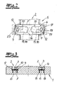
Die Figuren zeigen ein erfindungsgemäßes Gleiselement für Straßenbahnschienen und dergleichen. Zur Erstellung eines Gleises wird eine Mehrzahl der beispielsweise in Fig. 1 dargestellten Gleiselemente in Längsrichtung hintereinander angeordnet. Ein Gleiselement weist zunächst eine vorgefertigte Gleistragplatte 1 auf, die als Fertigteil angeliefert und verlegt werden kann. Diese vorgefertigte Gleistragplatte 1 besteht zweckmäßigerweise aus bewehrtem Beton, vorzugsweise aus Stahlbeton. Sie weist im Ausführungsbeispiel bereits werkseitig vorgefertigte parallele Aufnahmekanäle 2 für die Schienen 3 auf. Die Schienen 3 werden vorzugsweise erst vor Ort in den Aufnahmekanälen 2 der Gleistragplatte 1 justiert und befestigt und zwar mit Befestigungseinrichtungen 4. Im Ausführungsbeispiel sind die Schienen 3 quasi über ihre gesamte Höhe h in den Aufnahmekanälen 2 der Gleistragplatte 1 aufgenommen (siehe insbesondere Fig. 4 und 6). Die Schienen können oben geringfügig aus dem Aufnahmekanal 2 herausragen. Jede Schiene 3 ist an einer Mehrzahl von in Längsrichtung des zugeordneten Aufnahmekanals 2 beabstandet angeordneten Befestigungsstellen 5 mit den Befestigungseinrichtungen 4 in dem Aufnahmekanal 2 und zwar zweckmäßigerweise am Boden 6 des Aufnahmekanals 2 befestigt. Der Abstand zwischen zwei Befestigungsstellen 5 ist vorzugsweise und im Ausführungsbeispiel größer als 25cmThe figures show an inventive track element for tram rails and the like. To create a track, a plurality of the track elements shown for example in FIG. 1 are arranged one behind the other in the longitudinal direction. A track element initially has a prefabricated
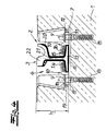
Nach bevorzugter Ausführungsform und im Ausführungsbeispiel weist die vorgefertigte Gleistragplatte 1 an jeder Befestigungsstelle 5 eine Basisplatte 7 auf, die am Boden 6 des jeweiligen Aufnahmekanals 2 fixiert ist und zwar vorzugsweise dort in die Gleistragplatte 1 einbetoniert ist. Gemäß dieser Ausführungsform weist also die als Fertigteil eingesetzte Gleistragplatte 1 bereits die einbetonierten Basisplatten 7 auf. Die Schienen 3 werden auf diesen Basisplatten 7 befestigt. Vorzugsweise und im Ausführungsbeispiel sind an jeder Befestigungsstelle 5 im Übrigen zwei Befestigungsdübel 8 vorgesehen und zwar je ein Befestigungsdübel 8 an jeder Seite der zu befestigenden Schiene 3. Nach bevorzugter Ausführungsvariante und im Ausführungsbeispiel sind diese Befestigungsdübel 8 in die vorgefertigte Gleistragplatte 1 einbetoniert. Mit anderen Worten weist die als Fertigteil eingesetzte Gleistragplatte 1 bereits die einbetonierten Befestigungsdübel 8 auf. Jedem Befestigungsdübel 8 ist eine Befestigungsschraube 9 zur Befestigung der Schiene 3 zugeordnet. Eine Befestigungsschraube 9 durchgreift im montierten Zustand (siehe insbesondere Fig. 4 und 6) eine Öffnung eines Fixierungselementes 10 sowie eine Öffnung 11 in der Basisplatte 7.According to a preferred embodiment and in the embodiment, the prefabricated
Jede Befestigungseinrichtung 4 für die Schienen 3 weist im Ausführungsbeispiel neben der Basisplatte 7, den Befestigungsdübeln 8 und den Befestigungsschrauben 9 zumindest zwei Fixierungselemente 10 auf. Im Ausführungsbeispiel sind an jeder Befestigungsstelle 5 zwei Fixierungselemente 10 vorgesehen und zwar jeweils ein Fixierungselement 10 an jeder Seite der zu befestigenden Schiene 3. Ein Fixierungselement 10 weist einen Fixierungsabschnitt 12 auf, in dem sich die Öffnung befindet, die die Befestigungsschraube 9 im montierten Zustand durchgreift. Das Fixierungselement 10 weist weiterhin einen den Schienenfuß 13 übergreifenden Halteabschnitt 14 auf. Im montierten Zustand, d. h. bei angezogener Befestigungsschraube 9 überfasst dieser Halteabschnitt 14 den Schienenfuß 13 klemmend.Each
Auf diese Weise wird die Schiene 3 mit den Fixierungselementen 10 bzw. mit deren Hafteabschnitten 14 fixiert.In this way, the
Im Ausführungsbeispiel weist jedes Fixierungselement 10 bzw. jeder Halteabschnitt 14 des Fixierungselementes 10 einen Aufnahmeraum 15 für ein Federelement 16 auf. Das Federelement 16 wird im montierten Zustand des Fixierungselementes 10 von dem Halteabschnitt 14 gegen den Schienenfuß 13 gedrückt. Dadurch wird das Federelement 16 unter Vorspannung gesetzt. Durch die Höhe des Aufnahmeraumes 15 im Halteabschnitt 14 kann die Vorspannung des Federelementes 16 gezielt eingestellt werden. Bei dem Federelement 16 handelt es sich nach sehr bevorzugter Ausführungsform der Erfindung und im Ausführungsbeispiel um ein Elastomerelement bzw. um eine Elastomerfeder. Die Elastomerfeder ist ebenso wie der Aufnahmeraum 15 des Halteabschnittes 14 im Ausführungsbeispiel zylinderförmig ausgebildet. Der Halteabschnitt 14 bildet gleichsam eine Schutzabdeckung für das Federelement 16 bzw. für die Elastomerfeder. Wenn die Schiene 3 in dem zugeordneten Aufnahmekanal 2 eingebettet werden soll bzw. einbetoniert werden soll schützt der Halteabschnitt 14 (Schutzabdeckung) die Elastomerfeder vor eindringendem Einbettungsmaterial bzw. vor eindringendem Beton. Auch ansonsten bildet der Halteabschnitt 14 eine effektive Schutzabdeckung und gewährleistet langfristig die federnde Wirkung des Federelementes 16. Im Ausführungsbeispiel deckt der Halteabschnitt 14 das Federelement 16 oberseitig und seitlich ab, so dass der Aufnahmeraum 15 nur nach unten zum Schienenfuß 13 hin geöffnet ist.In the exemplary embodiment, each fixing
In der Fig. 2 ist erkennbar, dass nach bevorzugter Ausführungsform und im Ausführungsbeispiel die in dem Fixierungsabschnitt 12 des Fixierungselementes 10 für die Befestigungsschraube 9 vorgesehene Öffnung als Langloch 17 ausgebildet ist. Die Längsachse des Langloches 17 ist dabei vorzugsweise schräg zur Längsachse des Aufnahmekanals 2 angeordnet. Die Längsachse des Langloches 17 bildet zweckmäßigerweise mit der Längsachse des Aufnahmekanals 2 bzw. mit der Längsachse der zu befestigenden Schiene 3 einen Winkel von 5° bis 30°, vorzugsweise einen Winkel von 10° bis 20°. Die beiden an einer Befestigungsstelle 5 gegenüberliegenden Langlöcher 17 ermöglichen bei eingesetzten, aber noch nicht vollständig angezogenen Befestigungsschrauben 9 eine Verschiebung der Fixierungselemente 10 in Richtung der Längsachsen der Langlöcher 17. Dadurch kann die zu befestigende Schiene 3 präzise justiert werden und auf diese Weise kann die Spurweite eines Gleises sehr exakt eingestellt werden. Die äußere Kante 18 der Fixierungselemente 10 ist im Übrigen vorzugsweise ebenfalls schräg ausgebildet und zwar bevorzugt parallel zur Längsachse des zugeordneten Langloches 17. Diese äußere Kante 18 liegt zweckmäßigerweise an einem ebenfalls parallel zur Längsachse des zugeordneten Langloches 17 angeordneten schrägen Anschlag 19 an. Das Fixierungselement 10 kann dann bei einer Verschiebung in Richtung der Längsachse des Langloches 17 mit seiner äußeren Kante 18 funktionssicher an dem schrägen Anschlag 19 anliegend verschoben werden. Der schräge Anschlag 19 kann Bestandteil der einbetonierten Basisplatte 7 sein, indem dieser schräge Anschlag 19 aus der Oberfläche der Basisplatte nach oben vorsteht. Der schräge Anschlag 19 kann aber auch von dem Material bzw. von dem Beton der vorgefertigten Gleistragplatte gebildet sein. Dann sind die schrägen Anschläge 19 bereits Bestandteil einer als Fertigteil eingesetzten Gleistragplatte 1.In FIG. 2 it can be seen that according to the preferred embodiment and in the exemplary embodiment, the opening provided in the fixing
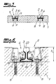
Nach besonders bevorzugter Ausführungsform und im Ausführungsbeispiel weisen die Schienen 3 eine sich in Schienenlängsrichtung erstreckende Elastomerummantelung 20 auf. Die Elastomerummantelung 20 ist zweckmäßigerweise in Längsrichtung einer Schiene 3 durchgehend vorgesehen bzw. im Wesentlichen durchgehend vorgesehen. Vorzugsweise und im Ausführungsbeispiel ist der Schienenfuß 13, der Schienensteg 21 und die Unterseite des Schienenkopfes 22 mit der Elastomerummantelung 20 versehen. Bevorzugt weist auch die Unterseite des Schienenfußes 13 diese Elastomerummantelung 20 auf, so dass eine Elastomerschicht zwischen Schienenfuß 13 und Basisplatte 7 angeordnet ist. Die Ausführungsform mit der Elastomerummantelung 20 hat sich im Rahmen der Erfindung besonders bewährt und zwar vor allem in Kombination mit dem Federelement 16 bzw. mit dem als Elastomerfeder ausgebildeten Federelement 16. Die Elastomerummantelung 20 besteht vorzugsweise aus Kautschukgummi.According to a particularly preferred embodiment and in the exemplary embodiment, the
In der Fig. 1 ist im Übrigen erkennbar, dass die Aufnahmekanäle 2 an den Befestigungsstellen 5 seitliche Aufweitungen 23 aufweisen. Mit anderen Worten ist ein Aufnahmekanal 2 an den Befestigungsstellen 5 zweckmäßigerweise breiter als in seinen übrigen Bereichen. In den Fig. 3 bis 6 ist erkennbar, dass die Aufnahmekanäle 2 vorzugsweise einen trapezförmigen Querschnitt haben, wobei sich die Breite eines Aufnahmekanals 2 vom Boden 6 nach oben hin verjüngt. Wenn die Schienen 3 in den Aufnahmekanälen 2 an den Befestigungsstellen 5 befestigt sind, werden anschließend die Aufnahmekanäle 2 zweckmäßigerweise mit einem Einbettungsmaterial verfüllt, beispielsweise mit Beton verfüllt. - Im Ausführungsbeispiel nach den Fig. 3 und 4 sind als Schienen Rillenschienen eingesetzt. Dagegen sind im Ausführungsbeispiel nach den Fig. 5 und 6 Kopfschienen (Vignolschienen) als Schienen 3 eingesetzt. Beide Arten von Schienen sind für die erfindungsgemäßen Gleiselemente gut geeignet.In addition, it can be seen in FIG. 1 that the receiving
Claims (11)
wobei die vorgefertigte Gleistragplatte (1) zumindest zwei parallele Aufnahmekanäle (2) für die Schienen (3) aufweist, in denen die Schienen (3) jeweils zumindest über den Großteil ihrer Höhe aufgenommen sind,
wobei jede Schiene (3) an einer Mehrzahl von in Längsrichtung des zugeordneten Aufnahmekanals (2) beabstandet angeordneten Befestigungsstellen (5) mit den Befestigungseinrichtungen (4) in dem Aufnahmekanal (2) befestigt ist,
wobei eine Befestigungseinrichtung (4) zumindest ein auf den Schienenfuß (13) der zugeordneten Schiene (3) einwirkendes Federelement (16) aufweist und wobei dieses Federelement (16) eine oberseitige Schutzabdeckung aufweist.Track element for tram rails and the like, - with a prefabricated track base plate (1), at least two rails (3) fixed to the track plate (1) and with fastening devices (4) for fastening the rails (3),
the prefabricated track carrier plate (1) having at least two parallel receiving channels (2) for the rails (3), in which the rails (3) are respectively received over at least the major part of their height,
each rail (3) being fastened to the mounting channel (2) at a plurality of fixing points (5) spaced apart in the longitudinal direction of the associated receiving channel (2) with the fastening devices (4),
wherein a fastening device (4) has at least one spring element (16) acting on the rail foot (13) of the associated rail (3), and wherein this spring element (16) has an upper-side protective cover.
Priority Applications (3)
| Application Number | Priority Date | Filing Date | Title |
|---|---|---|---|
| AT06004197T ATE469269T1 (en) | 2006-03-02 | 2006-03-02 | TRACK ELEMENT FOR TRAM RAILS AND THE LIKE |
| DE502006007022T DE502006007022D1 (en) | 2006-03-02 | 2006-03-02 | Track element for tram rails and the like |
| EP06004197A EP1830002B1 (en) | 2006-03-02 | 2006-03-02 | Track structure adapted for tramways |
Applications Claiming Priority (1)
| Application Number | Priority Date | Filing Date | Title |
|---|---|---|---|
| EP06004197A EP1830002B1 (en) | 2006-03-02 | 2006-03-02 | Track structure adapted for tramways |
Publications (2)
| Publication Number | Publication Date |
|---|---|
| EP1830002A1 true EP1830002A1 (en) | 2007-09-05 |
| EP1830002B1 EP1830002B1 (en) | 2010-05-26 |
Family
ID=36613402
Family Applications (1)
| Application Number | Title | Priority Date | Filing Date |
|---|---|---|---|
| EP06004197A Not-in-force EP1830002B1 (en) | 2006-03-02 | 2006-03-02 | Track structure adapted for tramways |
Country Status (3)
| Country | Link |
|---|---|
| EP (1) | EP1830002B1 (en) |
| AT (1) | ATE469269T1 (en) |
| DE (1) | DE502006007022D1 (en) |
Cited By (1)
| Publication number | Priority date | Publication date | Assignee | Title |
|---|---|---|---|---|
| DE102010009619A1 (en) | 2010-03-01 | 2011-09-01 | Phoenix Dichtungstechnik Gmbh | Profile for the elastic mounting of rails |
Citations (6)
| Publication number | Priority date | Publication date | Assignee | Title |
|---|---|---|---|---|
| DE4007937A1 (en) * | 1990-03-13 | 1991-09-19 | Krupp Lonrho Gmbh | Resilient rail for rail vehicles - has relatively adjustable frame side walls drawn together by bolts against resilient |
| DE4212679A1 (en) * | 1992-04-15 | 1993-10-21 | Butzbacher Weichenbau Gmbh | Arrangement of rail on sleeper - has holder, which partially encloses rail foot, and also contain a clamp spring |
| EP0794290A1 (en) * | 1996-03-07 | 1997-09-10 | Fried. Krupp AG Hoesch-Krupp | Laterally adjustable elastic rail fastening |
| EP1264932A2 (en) * | 2001-06-08 | 2002-12-11 | Matthias Müller | Rail fastening |
| EP1279770A2 (en) * | 2001-07-25 | 2003-01-29 | Patrick Vanhonacker | Railway support system for rails |
| WO2004033795A1 (en) * | 2002-10-08 | 2004-04-22 | Hyperlast Limited | Cladding of rails |
-
2006
- 2006-03-02 DE DE502006007022T patent/DE502006007022D1/en active Active
- 2006-03-02 EP EP06004197A patent/EP1830002B1/en not_active Not-in-force
- 2006-03-02 AT AT06004197T patent/ATE469269T1/en active
Patent Citations (6)
| Publication number | Priority date | Publication date | Assignee | Title |
|---|---|---|---|---|
| DE4007937A1 (en) * | 1990-03-13 | 1991-09-19 | Krupp Lonrho Gmbh | Resilient rail for rail vehicles - has relatively adjustable frame side walls drawn together by bolts against resilient |
| DE4212679A1 (en) * | 1992-04-15 | 1993-10-21 | Butzbacher Weichenbau Gmbh | Arrangement of rail on sleeper - has holder, which partially encloses rail foot, and also contain a clamp spring |
| EP0794290A1 (en) * | 1996-03-07 | 1997-09-10 | Fried. Krupp AG Hoesch-Krupp | Laterally adjustable elastic rail fastening |
| EP1264932A2 (en) * | 2001-06-08 | 2002-12-11 | Matthias Müller | Rail fastening |
| EP1279770A2 (en) * | 2001-07-25 | 2003-01-29 | Patrick Vanhonacker | Railway support system for rails |
| WO2004033795A1 (en) * | 2002-10-08 | 2004-04-22 | Hyperlast Limited | Cladding of rails |
Cited By (2)
| Publication number | Priority date | Publication date | Assignee | Title |
|---|---|---|---|---|
| DE102010009619A1 (en) | 2010-03-01 | 2011-09-01 | Phoenix Dichtungstechnik Gmbh | Profile for the elastic mounting of rails |
| EP2363530A1 (en) | 2010-03-01 | 2011-09-07 | voestalpine Klöckner Bahntechnik GmbH | Profile for elastic bearing of rails |
Also Published As
| Publication number | Publication date |
|---|---|
| ATE469269T1 (en) | 2010-06-15 |
| EP1830002B1 (en) | 2010-05-26 |
| DE502006007022D1 (en) | 2010-07-08 |
Similar Documents
| Publication | Publication Date | Title |
|---|---|---|
| EP2229479B1 (en) | Support for a rail fastening system and rail fastening system | |
| EP2318589B1 (en) | Device for mounting railroad tracks on a substructure | |
| DE202006020567U1 (en) | System for fastening a rail | |
| EP0937181B1 (en) | Railroad substructure | |
| DE10138803A1 (en) | Process for the continuous storage of a rail on a fixed carriageway, and adjusting device and fixed carriageway | |
| DE202007018566U1 (en) | System for securing a rail on a level solid surface | |
| EP3597825A1 (en) | Rail fastening system | |
| EP0432357A1 (en) | Device for applying rails for rail vehicles | |
| DE102007044098B3 (en) | Railway track fixing system, has elastic members supported on guidance plates, and bulges and recesses of bearing faces extended in parallel with horizontal rigid foundation under assembling condition of wedge-shaped members | |
| EP3437954B1 (en) | Protection device | |
| DE4328185C1 (en) | Bridge beam (sleeper) with means for fastening to girders of a steel railway bridge | |
| EP1830002B1 (en) | Track structure adapted for tramways | |
| DE102011003216A1 (en) | Mounting structure for mounting rail on railway sleepers, has receiving trough including flank whose height is set such that angular guide plate and height-adjusting plate are not extended over flank | |
| EP0853706B1 (en) | Level crossing | |
| EP0952252B1 (en) | Shuttering for embedding a rail | |
| AT411694B (en) | DEVICE FOR THE ELASTIC STORAGE OF A RILLED RAIL | |
| DE10157676A1 (en) | Device for the lateral support of a rail | |
| EP2800833B1 (en) | Slab track | |
| DE850457C (en) | Overhead fastening made of reinforced concrete slabs for track systems | |
| DE102008026693A1 (en) | Device for bridging expansion joints between two parts of structure i.e. bridge, has tie bar that is arranged at free lower end of pin below plate, where dimensions of bar are greater than that of through hole in plate | |
| DE102020113136A1 (en) | Shift protection device for surface covering elements and surface covering element with such a shift protection device | |
| DE19920075A1 (en) | Rail mounting system comprises profiles which support rail on each side and rail bed with ramp section contacting one profiles, third profile contacting other profile and other side of rail bed and being fastened to bed with bolts | |
| DE4325869C2 (en) | Fixed track for rail-bound traffic | |
| AT375699B (en) | RAIL ARRANGEMENT, IN PARTICULAR FOR TRAMWAY TRACKS | |
| DE102004050175B3 (en) | Transverse base plate for railway or street car track has raised profile with clamping channel open at each end |
Legal Events
| Date | Code | Title | Description |
|---|---|---|---|
| PUAI | Public reference made under article 153(3) epc to a published international application that has entered the european phase |
Free format text: ORIGINAL CODE: 0009012 |
|
| AK | Designated contracting states |
Kind code of ref document: A1 Designated state(s): AT BE BG CH CY CZ DE DK EE ES FI FR GB GR HU IE IS IT LI LT LU LV MC NL PL PT RO SE SI SK TR |
|
| AX | Request for extension of the european patent |
Extension state: AL BA HR MK YU |
|
| 17P | Request for examination filed |
Effective date: 20070921 |
|
| AKX | Designation fees paid |
Designated state(s): AT BE BG CH CY CZ DE DK EE ES FI FR GB GR HU IE IS IT LI LT LU LV MC NL PL PT RO SE SI SK TR |
|
| GRAP | Despatch of communication of intention to grant a patent |
Free format text: ORIGINAL CODE: EPIDOSNIGR1 |
|
| GRAS | Grant fee paid |
Free format text: ORIGINAL CODE: EPIDOSNIGR3 |
|
| GRAA | (expected) grant |
Free format text: ORIGINAL CODE: 0009210 |
|
| AK | Designated contracting states |
Kind code of ref document: B1 Designated state(s): AT BE BG CH CY CZ DE DK EE ES FI FR GB GR HU IE IS IT LI LT LU LV MC NL PL PT RO SE SI SK TR |
|
| REG | Reference to a national code |
Ref country code: GB Ref legal event code: FG4D Free format text: NOT ENGLISH |
|
| REG | Reference to a national code |
Ref country code: CH Ref legal event code: EP |
|
| REG | Reference to a national code |
Ref country code: IE Ref legal event code: FG4D Free format text: LANGUAGE OF EP DOCUMENT: GERMAN |
|
| REF | Corresponds to: |
Ref document number: 502006007022 Country of ref document: DE Date of ref document: 20100708 Kind code of ref document: P |
|
| REG | Reference to a national code |
Ref country code: NL Ref legal event code: VDEP Effective date: 20100526 |
|
| LTIE | Lt: invalidation of european patent or patent extension |
Effective date: 20100526 |
|
| PG25 | Lapsed in a contracting state [announced via postgrant information from national office to epo] |
Ref country code: LT Free format text: LAPSE BECAUSE OF FAILURE TO SUBMIT A TRANSLATION OF THE DESCRIPTION OR TO PAY THE FEE WITHIN THE PRESCRIBED TIME-LIMIT Effective date: 20100526 Ref country code: SE Free format text: LAPSE BECAUSE OF FAILURE TO SUBMIT A TRANSLATION OF THE DESCRIPTION OR TO PAY THE FEE WITHIN THE PRESCRIBED TIME-LIMIT Effective date: 20100526 |
|
| PG25 | Lapsed in a contracting state [announced via postgrant information from national office to epo] |
Ref country code: LV Free format text: LAPSE BECAUSE OF FAILURE TO SUBMIT A TRANSLATION OF THE DESCRIPTION OR TO PAY THE FEE WITHIN THE PRESCRIBED TIME-LIMIT Effective date: 20100526 Ref country code: SI Free format text: LAPSE BECAUSE OF FAILURE TO SUBMIT A TRANSLATION OF THE DESCRIPTION OR TO PAY THE FEE WITHIN THE PRESCRIBED TIME-LIMIT Effective date: 20100526 Ref country code: FI Free format text: LAPSE BECAUSE OF FAILURE TO SUBMIT A TRANSLATION OF THE DESCRIPTION OR TO PAY THE FEE WITHIN THE PRESCRIBED TIME-LIMIT Effective date: 20100526 Ref country code: IS Free format text: LAPSE BECAUSE OF FAILURE TO SUBMIT A TRANSLATION OF THE DESCRIPTION OR TO PAY THE FEE WITHIN THE PRESCRIBED TIME-LIMIT Effective date: 20100926 |
|
| PG25 | Lapsed in a contracting state [announced via postgrant information from national office to epo] |
Ref country code: PL Free format text: LAPSE BECAUSE OF FAILURE TO SUBMIT A TRANSLATION OF THE DESCRIPTION OR TO PAY THE FEE WITHIN THE PRESCRIBED TIME-LIMIT Effective date: 20100526 Ref country code: CY Free format text: LAPSE BECAUSE OF FAILURE TO SUBMIT A TRANSLATION OF THE DESCRIPTION OR TO PAY THE FEE WITHIN THE PRESCRIBED TIME-LIMIT Effective date: 20100526 |
|
| REG | Reference to a national code |
Ref country code: IE Ref legal event code: FD4D |
|
| PG25 | Lapsed in a contracting state [announced via postgrant information from national office to epo] |
Ref country code: PT Free format text: LAPSE BECAUSE OF FAILURE TO SUBMIT A TRANSLATION OF THE DESCRIPTION OR TO PAY THE FEE WITHIN THE PRESCRIBED TIME-LIMIT Effective date: 20100927 Ref country code: EE Free format text: LAPSE BECAUSE OF FAILURE TO SUBMIT A TRANSLATION OF THE DESCRIPTION OR TO PAY THE FEE WITHIN THE PRESCRIBED TIME-LIMIT Effective date: 20100526 Ref country code: DK Free format text: LAPSE BECAUSE OF FAILURE TO SUBMIT A TRANSLATION OF THE DESCRIPTION OR TO PAY THE FEE WITHIN THE PRESCRIBED TIME-LIMIT Effective date: 20100526 Ref country code: NL Free format text: LAPSE BECAUSE OF FAILURE TO SUBMIT A TRANSLATION OF THE DESCRIPTION OR TO PAY THE FEE WITHIN THE PRESCRIBED TIME-LIMIT Effective date: 20100526 Ref country code: IE Free format text: LAPSE BECAUSE OF FAILURE TO SUBMIT A TRANSLATION OF THE DESCRIPTION OR TO PAY THE FEE WITHIN THE PRESCRIBED TIME-LIMIT Effective date: 20100526 |
|
| PG25 | Lapsed in a contracting state [announced via postgrant information from national office to epo] |
Ref country code: SK Free format text: LAPSE BECAUSE OF FAILURE TO SUBMIT A TRANSLATION OF THE DESCRIPTION OR TO PAY THE FEE WITHIN THE PRESCRIBED TIME-LIMIT Effective date: 20100526 Ref country code: RO Free format text: LAPSE BECAUSE OF FAILURE TO SUBMIT A TRANSLATION OF THE DESCRIPTION OR TO PAY THE FEE WITHIN THE PRESCRIBED TIME-LIMIT Effective date: 20100526 Ref country code: CZ Free format text: LAPSE BECAUSE OF FAILURE TO SUBMIT A TRANSLATION OF THE DESCRIPTION OR TO PAY THE FEE WITHIN THE PRESCRIBED TIME-LIMIT Effective date: 20100526 |
|
| PG25 | Lapsed in a contracting state [announced via postgrant information from national office to epo] |
Ref country code: IT Free format text: LAPSE BECAUSE OF FAILURE TO SUBMIT A TRANSLATION OF THE DESCRIPTION OR TO PAY THE FEE WITHIN THE PRESCRIBED TIME-LIMIT Effective date: 20100526 |
|
| PLBE | No opposition filed within time limit |
Free format text: ORIGINAL CODE: 0009261 |
|
| STAA | Information on the status of an ep patent application or granted ep patent |
Free format text: STATUS: NO OPPOSITION FILED WITHIN TIME LIMIT |
|
| 26N | No opposition filed |
Effective date: 20110301 |
|
| REG | Reference to a national code |
Ref country code: DE Ref legal event code: R097 Ref document number: 502006007022 Country of ref document: DE Effective date: 20110228 |
|
| BERE | Be: lapsed |
Owner name: BTE STELCON DEUTSCHLAND G.M.B.H. Effective date: 20110331 Owner name: VOESTALPINE KLOCKNER BAHNTECHNIK G.M.B.H. Effective date: 20110331 |
|
| PG25 | Lapsed in a contracting state [announced via postgrant information from national office to epo] |
Ref country code: MC Free format text: LAPSE BECAUSE OF NON-PAYMENT OF DUE FEES Effective date: 20110331 |
|
| REG | Reference to a national code |
Ref country code: CH Ref legal event code: PL |
|
| GBPC | Gb: european patent ceased through non-payment of renewal fee |
Effective date: 20110302 |
|
| REG | Reference to a national code |
Ref country code: FR Ref legal event code: ST Effective date: 20111130 |
|
| PG25 | Lapsed in a contracting state [announced via postgrant information from national office to epo] |
Ref country code: BE Free format text: LAPSE BECAUSE OF NON-PAYMENT OF DUE FEES Effective date: 20110331 |
|
| PG25 | Lapsed in a contracting state [announced via postgrant information from national office to epo] |
Ref country code: CH Free format text: LAPSE BECAUSE OF NON-PAYMENT OF DUE FEES Effective date: 20110331 Ref country code: FR Free format text: LAPSE BECAUSE OF NON-PAYMENT OF DUE FEES Effective date: 20110331 Ref country code: LI Free format text: LAPSE BECAUSE OF NON-PAYMENT OF DUE FEES Effective date: 20110331 |
|
| PG25 | Lapsed in a contracting state [announced via postgrant information from national office to epo] |
Ref country code: GB Free format text: LAPSE BECAUSE OF NON-PAYMENT OF DUE FEES Effective date: 20110302 |
|
| REG | Reference to a national code |
Ref country code: AT Ref legal event code: MM01 Ref document number: 469269 Country of ref document: AT Kind code of ref document: T Effective date: 20110302 |
|
| PG25 | Lapsed in a contracting state [announced via postgrant information from national office to epo] |
Ref country code: AT Free format text: LAPSE BECAUSE OF NON-PAYMENT OF DUE FEES Effective date: 20110302 |
|
| PG25 | Lapsed in a contracting state [announced via postgrant information from national office to epo] |
Ref country code: LU Free format text: LAPSE BECAUSE OF NON-PAYMENT OF DUE FEES Effective date: 20110302 |
|
| PG25 | Lapsed in a contracting state [announced via postgrant information from national office to epo] |
Ref country code: BG Free format text: LAPSE BECAUSE OF FAILURE TO SUBMIT A TRANSLATION OF THE DESCRIPTION OR TO PAY THE FEE WITHIN THE PRESCRIBED TIME-LIMIT Effective date: 20100826 Ref country code: TR Free format text: LAPSE BECAUSE OF FAILURE TO SUBMIT A TRANSLATION OF THE DESCRIPTION OR TO PAY THE FEE WITHIN THE PRESCRIBED TIME-LIMIT Effective date: 20100526 |
|
| PG25 | Lapsed in a contracting state [announced via postgrant information from national office to epo] |
Ref country code: ES Free format text: LAPSE BECAUSE OF FAILURE TO SUBMIT A TRANSLATION OF THE DESCRIPTION OR TO PAY THE FEE WITHIN THE PRESCRIBED TIME-LIMIT Effective date: 20100906 Ref country code: HU Free format text: LAPSE BECAUSE OF FAILURE TO SUBMIT A TRANSLATION OF THE DESCRIPTION OR TO PAY THE FEE WITHIN THE PRESCRIBED TIME-LIMIT Effective date: 20100526 |
|
| PG25 | Lapsed in a contracting state [announced via postgrant information from national office to epo] |
Ref country code: GR Free format text: LAPSE BECAUSE OF FAILURE TO SUBMIT A TRANSLATION OF THE DESCRIPTION OR TO PAY THE FEE WITHIN THE PRESCRIBED TIME-LIMIT Effective date: 20100526 |
|
| PGFP | Annual fee paid to national office [announced via postgrant information from national office to epo] |
Ref country code: DE Payment date: 20170403 Year of fee payment: 12 |
|
| REG | Reference to a national code |
Ref country code: DE Ref legal event code: R119 Ref document number: 502006007022 Country of ref document: DE |
|
| PG25 | Lapsed in a contracting state [announced via postgrant information from national office to epo] |
Ref country code: DE Free format text: LAPSE BECAUSE OF NON-PAYMENT OF DUE FEES Effective date: 20181002 |