EP1279770A2 - Railway support system for rails - Google Patents
Railway support system for rails Download PDFInfo
- Publication number
- EP1279770A2 EP1279770A2 EP02447141A EP02447141A EP1279770A2 EP 1279770 A2 EP1279770 A2 EP 1279770A2 EP 02447141 A EP02447141 A EP 02447141A EP 02447141 A EP02447141 A EP 02447141A EP 1279770 A2 EP1279770 A2 EP 1279770A2
- Authority
- EP
- European Patent Office
- Prior art keywords
- slab
- vibration
- rail
- rails
- support system
- Prior art date
- Legal status (The legal status is an assumption and is not a legal conclusion. Google has not performed a legal analysis and makes no representation as to the accuracy of the status listed.)
- Withdrawn
Links
Images


Classifications
-
- E—FIXED CONSTRUCTIONS
- E01—CONSTRUCTION OF ROADS, RAILWAYS, OR BRIDGES
- E01B—PERMANENT WAY; PERMANENT-WAY TOOLS; MACHINES FOR MAKING RAILWAYS OF ALL KINDS
- E01B19/00—Protection of permanent way against development of dust or against the effect of wind, sun, frost, or corrosion; Means to reduce development of noise
- E01B19/003—Means for reducing the development or propagation of noise
-
- E—FIXED CONSTRUCTIONS
- E01—CONSTRUCTION OF ROADS, RAILWAYS, OR BRIDGES
- E01B—PERMANENT WAY; PERMANENT-WAY TOOLS; MACHINES FOR MAKING RAILWAYS OF ALL KINDS
- E01B1/00—Ballastway; Other means for supporting the sleepers or the track; Drainage of the ballastway
- E01B1/008—Drainage of track
-
- E—FIXED CONSTRUCTIONS
- E01—CONSTRUCTION OF ROADS, RAILWAYS, OR BRIDGES
- E01B—PERMANENT WAY; PERMANENT-WAY TOOLS; MACHINES FOR MAKING RAILWAYS OF ALL KINDS
- E01B2/00—General structure of permanent way
-
- E—FIXED CONSTRUCTIONS
- E01—CONSTRUCTION OF ROADS, RAILWAYS, OR BRIDGES
- E01B—PERMANENT WAY; PERMANENT-WAY TOOLS; MACHINES FOR MAKING RAILWAYS OF ALL KINDS
- E01B21/00—Track superstructure adapted for tramways in paved streets
- E01B21/02—Special supporting means; Draining of rails
-
- E—FIXED CONSTRUCTIONS
- E01—CONSTRUCTION OF ROADS, RAILWAYS, OR BRIDGES
- E01B—PERMANENT WAY; PERMANENT-WAY TOOLS; MACHINES FOR MAKING RAILWAYS OF ALL KINDS
- E01B35/00—Applications of measuring apparatus or devices for track-building purposes
- E01B35/12—Applications of measuring apparatus or devices for track-building purposes for measuring movement of the track or of the components thereof under rolling loads, e.g. depression of sleepers, increase of gauge
-
- E—FIXED CONSTRUCTIONS
- E01—CONSTRUCTION OF ROADS, RAILWAYS, OR BRIDGES
- E01B—PERMANENT WAY; PERMANENT-WAY TOOLS; MACHINES FOR MAKING RAILWAYS OF ALL KINDS
- E01B1/00—Ballastway; Other means for supporting the sleepers or the track; Drainage of the ballastway
- E01B1/001—Track with ballast
-
- E—FIXED CONSTRUCTIONS
- E01—CONSTRUCTION OF ROADS, RAILWAYS, OR BRIDGES
- E01B—PERMANENT WAY; PERMANENT-WAY TOOLS; MACHINES FOR MAKING RAILWAYS OF ALL KINDS
- E01B2203/00—Devices for working the railway-superstructure
- E01B2203/16—Guiding or measuring means, e.g. for alignment, canting, stepwise propagation
-
- E—FIXED CONSTRUCTIONS
- E01—CONSTRUCTION OF ROADS, RAILWAYS, OR BRIDGES
- E01B—PERMANENT WAY; PERMANENT-WAY TOOLS; MACHINES FOR MAKING RAILWAYS OF ALL KINDS
- E01B2204/00—Characteristics of the track and its foundations
- E01B2204/01—Elastic layers other than rail-pads, e.g. sleeper-shoes, bituconcrete
-
- E—FIXED CONSTRUCTIONS
- E01—CONSTRUCTION OF ROADS, RAILWAYS, OR BRIDGES
- E01B—PERMANENT WAY; PERMANENT-WAY TOOLS; MACHINES FOR MAKING RAILWAYS OF ALL KINDS
- E01B2204/00—Characteristics of the track and its foundations
- E01B2204/11—Embedded tracks, using prefab elements or injecting or pouring a curable material
Definitions
- the invention relates in particular to the problem of acoustic and anti-vibration insulation of railways installed on roads.
- the inventors set out to analyze the static behavior and the dynamic behavior of the railway track when a vehicle passes over the rails.
- a car traveling on the rails produces two impacts on the rails. The first is due to the mass of all the cars in the train: it is the static load transferred to the bogies; the second impact is due to the mass not suspended from the bogie: it is this mass which produces the dynamic impulses by the wheels on the rails and it is these impulses which are transmitted towards the environment.
- the first flexural resonance frequency of the wheel / rail assembly is conditioned by the dynamic stiffness of the soles placed under the rails and, if necessary, by that of the cushions placed under the saddles or crosspieces.
- This resonant frequency is inversely proportional to the anti-vibration performance of the rail fastening system.
- a low resonant frequency provides better vibration isolation than a high resonant frequency.
- Insulation performance Better antivibration is obtained by decoupling the fixing function and the insulation function.
- separating elements consisting of prefabricated elements or of a waterproof and flexible filling product, are chosen so that the static and dynamic stiffnesses of the assembly are less than those of the flanges placed under the pads of the rails.
- the rails are thus completely independent of the roads, which has the consequence of considerably reducing the transmission of vibrations to the foundations of neighboring buildings at the same time as sealing is ensured along the rails.
- a system in which the rail is coated with a very compact resilient material to give it better mechanical resistance to expansion and to the forces generated by the movement of cars on the rail does not have the static and dynamic characteristics required to ensure effective vibration isolation and, therefore, the transmission of vibration waves to the foundations of neighboring buildings is maximum.
- the rails can be fixed to the slab slab in different ways: by means of saddles or crosspieces or even by direct laying on the slab slab. Under the pad of each rail is usually interposed a rigid or anti-vibration sole. Often below and underneath each saddle or cross member is an anti-vibration pad.
- the slab slab has bowls to receive the lower part of the sleepers.
- the slab slab 15 rests on a layer of stabilized sand 17 placed on the bottom of the trunk (ground) 19.
- a draining layer 16 intended to drain water infiltration towards draining pipes 18 arranged at intervals along the track with a diameter and a spacing which are a function of the geographical location of the road.
- the slab slab ensures the stability of the installation.
- a layer of anti-vibration material can also be placed between the stabilized sand bed and the slab slab.
- the vacuum between the road slab 22 and the slab slab 15 is preferably filled by injection of a suitable filling product 28 chosen according to the degree of insulation required by the environment.
- the successive supports along the track are made so as to alternately constitute a support relatively rigid and relatively flexible support.
- FIG. 4 illustrates a case where the rail 11 is fixed to saddles 33 sealed in the slab slab 15, using an epoxy mortar, for example.
- the reference 31 designates a device for fixing a rail with joint bars.
- On the stabilized sand 17 are arranged, for example, a draining layer 35 and an anti-vibration isolation mat 37.
- the spaces between each rail 11 and the road slabs 21 and 22 are filled with separation elements 25 made of material having predetermined static and dynamic rigidities.
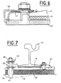
- FIG. 7 illustrates the fixing of a rail 11 on a saddle 43 which is itself fixed to the slab slab 15 by means of an adjustable fixing device 41 applying an adjustable preload to the anti-vibration sole 42 disposed under the saddle 43
- This fixing device provides antivibration isolation at low resonance frequency.
- the fixing device illustrated comprises a prestressing spring 45 held between two abutment washers around a threaded rod 44.
- the spring 45 is compressed by the clamping nut 46 which adjusts the prestressing force.
- the fixing device may also include two springs having rigidities different and held between two washers around the threaded rod 44, the springs being compressed by the clamping nut 46 which adjusts the prestressing force.
- the inventors have devised a measurement method by which the effects of the total static load applied to an axle of a vehicle having to travel on a railway track are decoupled from the equivalent of the unsprung mass of a bogie.
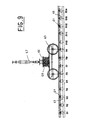
- the implementation of this method can be carried out, for example, using a test bench as shown diagrammatically in FIG. 9.
- the supports 61 are produced with static and dynamic stiffness chosen according to the actual operating conditions and the desired level of performance. For example, in the case where it is desired to optimize the antivibration isolation and limit the deflection of the rail, the supports 61 will be produced with alternating stiffnesses so as to be alternately a relatively rigid support R and a relatively flexible support S.
- load cell 64 By applying to load cell 64, a load in stages ranging from 0 to 250 kN, for example, and by moving the carriage along the section of track, it is possible to detect the static deflection of the rail to the right of each support.
- the natural frequency of the track system can be noted, the deflections in line with the supports and vibration damping of the rails to the right of each support.
- the analyzes thus carried out allow the designer of a railway track to be installed to determine in an optimal manner the particularities of the acoustic and anti-vibration insulation elements to be incorporated in the railroad support system in order to optimize the acoustic and anti-vibration insulation. and reduce the transmission of vibration waves to the environment.
Abstract
Description
La présente invention concerne l'installation de voies ferrées en voirie et en particulier l'installation de voies ferrées pour tramways.The present invention relates to the installation of railways on roads and in particular the installation of railways for trams.
L'installation de voies ferrées pour tramways en voirie pose un problème qui se situe à différents niveaux :
- a) Au niveau de la stabilité de la voie, les voies ballastées classiques posent un problème en voirie du fait de leur tassement dans le temps et de la destruction de la voirie dans la zone des voies ;
- b) Au niveau de l'environnement, l'impact des vibrations et des bruits par suite du tassement de la voirie et de l'augmentation de la raideur dynamique du ballast provoque des transmissions vibratoires vers les fondations des immeubles avoisinants ;
- c) Au niveau de la maintenance de la voie, les tassements localisés du ballast provoque une déflexion locale importante de la voie, ce qui entraîne une usure plus importante de l'infrastructure et du matériel roulant ;
- d) Au niveau de la mise en oeuvre de la voie ferrée et du temps d'exécution et d'accès pour assurer la maintenance.
- a) In terms of track stability, conventional ballasted tracks pose a problem on the roads due to their settlement over time and the destruction of the roads in the track area;
- b) In terms of the environment, the impact of vibrations and noises as a result of the compaction of the roads and the increase in the dynamic stiffness of the ballast causes vibration transmissions to the foundations of neighboring buildings;
- c) In terms of track maintenance, localized settling of the ballast causes significant local deflection of the track, which leads to greater wear of the infrastructure and rolling stock;
- d) At the level of the implementation of the railway and the execution and access time to ensure maintenance.
Le problème de stabilité de la voie est résolu par l'installation de la voie sur une dalle radier en béton. Une telle installation de voie ferrée se trouve décrite dans la publication WO 98/51863. Dans cette installation connue, aucune mesure n'est cependant prévue pour réduire la transmission des ondes acoustiques et vibratoires engendrées par le passage de véhicules sur la voie ferrée vers les fondations des immeubles avoisinants.The problem of track stability is solved by installing the track on a concrete slab slab. Such a railroad installation is described in publication WO 98/51863. In this known installation, however, no measure is planned to reduce the transmission of the acoustic and vibratory waves generated by the passage of vehicles on the railway towards the foundations of neighboring buildings.
L'invention concerne en particulier le problème de l'isolation acoustique et antivibratoire des voies ferrées installées en voirie. Afin de résoudre ce problème d'une manière globale, les inventeurs se sont attachés à analyser le comportement statique et le comportement dynamique de la voie ferrée lors du passage d'un véhicule sur les rails. Une voiture circulant sur les rails produit deux impacts sur les rails. Le premier est dû à la masse de l'ensemble des voitures de la rame : c'est la charge statique reportée sur les bogies ; le second impact est dû à la masse non suspendue du bogie : c'est cette masse qui produit les impulsions dynamiques par les roues sur les rails et ce sont ces impulsions qui se transmettent vers l'environnement.The invention relates in particular to the problem of acoustic and anti-vibration insulation of railways installed on roads. In order to solve this problem in a global manner, the inventors set out to analyze the static behavior and the dynamic behavior of the railway track when a vehicle passes over the rails. A car traveling on the rails produces two impacts on the rails. The first is due to the mass of all the cars in the train: it is the static load transferred to the bogies; the second impact is due to the mass not suspended from the bogie: it is this mass which produces the dynamic impulses by the wheels on the rails and it is these impulses which are transmitted towards the environment.
Globalement, les phénomènes acoustiques et vibratoires qui prennent naissance lors du passage d'une rame sur les supports des rails comprennent plusieurs composantes parmi lesquelles on peut citer :
- a) Une composante vibratoire constituée des ondes de chocs émises par le passage de la rame et propagées par le sol: la propagation de ces vibrations est fonction des caractéristiques intrinsèques du sol ;
- b) Des bruits solidiens résultant des vibrations des constructions produites par les ondes vibratoires transmises par le sol ;
- c) Des bruits aériens résultant de phénomènes ondulatoires transmis directement par l'air.
- a) A vibratory component consisting of shock waves emitted by the passage of the train and propagated by the ground: the propagation of these vibrations is a function of the intrinsic characteristics of the ground;
- b) Solid noises resulting from the vibrations of constructions produced by the vibratory waves transmitted by the ground;
- c) Airborne noise resulting from wave phenomena transmitted directly by the air.
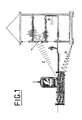
La transmission des ondes acoustiques et vibratoires engendrées lors du passage d'un tramway sur une voie ferrée en voirie est illustrée à la figure 1. Les ondes vibratoires A se propagent par le sol et sont engendrées par les chocs des roues des voitures du tramway sur les rails. Les bruits solidiens B résultent des vibrations des constructions avoisinantes recevant les ondes vibratoires A transmises par le sol. Les ondes C sont des bruits aériens résultant de phénomènes ondulatoires transmis directement par l'air. Le système d'appui de voie ferrée suivant l'invention vise à réduire à un minimum la transmission de ces phénomènes ondulatoires.The transmission of acoustic and vibration waves generated during the passage of a tram on a railroad track is illustrated in Figure 1. The vibration waves A are propagated by the ground and are generated by the impact of the wheels of the cars of the tram on rails. Solidiens noises B result from the vibrations of neighboring constructions receiving the vibratory waves A transmitted by the ground. C waves are air noises resulting from wave phenomena transmitted directly by the air. The rail support system according to the invention aims to reduce to a minimum the transmission of these wave phenomena.
La première fréquence de résonance en flexion de l'ensemble roue / rail est conditionnée par la raideur dynamique des semelles placées sous les rails et, le cas échéant, par celle des coussins placés sous les selles ou les traverses. Cette fréquence de résonance est inversement proportionnelle à la performance antivibratoire du système de fixation des rails. Une fréquence de résonance basse assure une meilleure isolation antivibratoire qu'une fréquence de résonance élevée. Cependant, il y a une limite physique inférieure en dessous de laquelle ne peut descendre la raideur dynamique des semelles utilisées car la raideur dynamique des semelles est en relation directe avec leur raideur statique et la raideur statique des semelles ne peut être trop faible car elle influence directement la déflexion des rails lors du passage d'un véhicule sur les rails. Des performances d'isolation antivibratoire meilleures sont obtenues en découplant la fonction de fixation et la fonction d'isolation.The first flexural resonance frequency of the wheel / rail assembly is conditioned by the dynamic stiffness of the soles placed under the rails and, if necessary, by that of the cushions placed under the saddles or crosspieces. This resonant frequency is inversely proportional to the anti-vibration performance of the rail fastening system. A low resonant frequency provides better vibration isolation than a high resonant frequency. However, there is a lower physical limit below which the dynamic stiffness of the soles used cannot go down because the dynamic stiffness of the soles is directly related to their static stiffness and the static stiffness of the soles cannot be too low because it influences the rail deflection directly when a vehicle passes over the rails. Insulation performance Better antivibration is obtained by decoupling the fixing function and the insulation function.
Pour résoudre le problème de l'isolation acoustique et antivibratoire qui surgit lors de l'exploitation d'une voie ferrée en voirie, il est donc nécessaire de prévoir un système de support antivibratoire approprié, qui soit adapté aux caractéristiques du sol et à la transmissibilité des ondes acoustiques et vibratoires vers l'environnement. Afin de mettre au point un tel système de support de manière à optimiser les performances d'isolation acoustique et antivibratoire, les inventeurs ont conçu un procédé et un dispositif pour analyser le comportement statique et le comportement dynamique d'une voie ferrée et déterminer la fréquence propre du système de la voie, les déflexions au droit des supports et l'amortissement des vibrations du rail. Ces analyses ont amené les inventeurs à déterminer les particularités à incorporer dans le système d'appui de voie ferrée afin d'optimiser l'isolation acoustique et antivibratoire et réduire la transmission des ondes vibratoires vers l'environnement.To solve the problem of acoustic and anti-vibration insulation which arises during the operation of a railway track on roads, it is therefore necessary to provide an appropriate anti-vibration support system, which is adapted to the characteristics of the ground and to the transmissibility acoustic and vibratory waves to the environment. In order to develop such a support system so as to optimize the performance of sound insulation and antivibration, the inventors have devised a method and a device for analyzing the static behavior and the dynamic behavior of a railway track and determining the frequency specific to the track system, deflections to the right of the supports and damping of rail vibrations. These analyzes have led the inventors to determine the features to be incorporated into the rail support system in order to optimize the acoustic and anti-vibration insulation and reduce the transmission of vibratory waves to the environment.
L'invention propose ainsi un système de support de voie ferrée dans lequel les rails de la voie sont fixés sur une dalle radier en béton armé préfabriquée ou coulée sur place, mise en place sur un lit de sable stabilisé posé sur le fond de coffre du site et, de chaque côté extérieur de la voie, est placée une dalle ou poutre de voirie préfabriquée scellée à un bord latéral de la dalle radier. Entre les rails de la voie est placée une dalle de voirie préfabriquée en béton armé. Dans le but de désolidariser les rails de la voirie et de ne pas neutraliser le comportement dynamique des rails, chaque rail est séparé des dalles de béton de voirie par des éléments de séparation qui isolent le rail de la dalle avoisinante. Ces éléments de séparation, constitués d'éléments préfabriqués ou d'un produit de remplissage étanche et souple, sont choisis de manière que les rigidités statique et dynamique de l'ensemble soient inférieures à celles des semelles placées sous les patins des rails. Les rails se trouvent ainsi totalement indépendants de la voirie, ce qui a pour conséquence de réduire considérablement la transmission des vibrations vers les fondations des immeubles avoisinants en même temps qu'est assurée une étanchéité le long des rails.The invention thus provides a railroad support system in which the rails of the track are fixed to a slab slab of prefabricated reinforced concrete or poured on site, placed on a bed of stabilized sand placed on the bottom of the trunk of the site and, on each outer side of the track, is placed a prefabricated road slab or beam sealed at a lateral edge of the slab slab. Between the rails of the track is placed a prefabricated reinforced concrete road slab. With the aim of separating the rails from the road network and not neutralizing the dynamic behavior of the rails, each rail is separated from the concrete road slabs by separation elements which isolate the rail from the neighboring slab. These separating elements, consisting of prefabricated elements or of a waterproof and flexible filling product, are chosen so that the static and dynamic stiffnesses of the assembly are less than those of the flanges placed under the pads of the rails. The rails are thus completely independent of the roads, which has the consequence of considerably reducing the transmission of vibrations to the foundations of neighboring buildings at the same time as sealing is ensured along the rails.
Un système dans lequel le rail est enrobé d'un matériau résilient très compact pour lui conférer une meilleure résistance mécanique aux dilatations et aux efforts engendrés par la circulation des voitures sur le rail ne présente pas les caractéristiques statiques et dynamiques requises pour assurer une isolation antivibratoire efficace et, dès lors, la transmission des ondes vibratoires vers les fondations des immeubles avoisinants est dans ce cas maximale.A system in which the rail is coated with a very compact resilient material to give it better mechanical resistance to expansion and to the forces generated by the movement of cars on the rail does not have the static and dynamic characteristics required to ensure effective vibration isolation and, therefore, the transmission of vibration waves to the foundations of neighboring buildings is maximum.
Dans le système de support de voie ferrée suivant l'invention, les rails peuvent être fixés sur la dalle radier de différentes manières : par l'intermédiaire de selles ou de traverses ou encore en pose directe sur la dalle radier. Sous le patin de chaque rail est habituellement interposée une semelle rigide ou antivibratoire. En dessous de chaque selle ou traverse est souvent et de préférence placé un coussin antivibratoire.In the railroad support system according to the invention, the rails can be fixed to the slab slab in different ways: by means of saddles or crosspieces or even by direct laying on the slab slab. Under the pad of each rail is usually interposed a rigid or anti-vibration sole. Often below and underneath each saddle or cross member is an anti-vibration pad.
Les semelles anti-vibratoires sont choisies avec des raideurs statiques et dynamiques telles que la première fréquence de résonance du système roue- rail-support soit située en dessous de 60 Hz environ. Ceci assure un filtre anti-vibratoire plus performant pour amortir les ondes vibratoires vers l'environnement. A titre de comparaison, la première fréquence de résonance d'une voie ballastée classique (système roue- rail- ballast) peut varier de 60 à 110 Hz. Une isolation antivibratoire performante est obtenue avec des dispositifs anti-vibratoires réalisés de manière que la rigidité statique soit inférieure à 2x10⁷ N/m et que la rigidité dynamique soit inférieure à 4x10⁷ N/m.The anti-vibration soles are chosen with static and dynamic stiffnesses such that the first resonance frequency of the wheel-rail-support system is located below approximately 60 Hz. This provides a more effective anti-vibration filter to dampen the vibration waves to the environment. For comparison, the first resonance frequency of a conventional ballasted track (wheel-rail-ballast system) can vary from 60 to 110 Hz. A high-performance antivibration isolation is obtained with anti-vibration devices made so that the rigidity static is less than 2x10 7 N / m and that the dynamic rigidity is less than 4x10 7 N / m.
Pour limiter la déflexion du rail lors du passage des roues à une valeur tolérable de 1 à 2 mm, il faut choisir pour les semelles ou les appuis antivibratoires des raideurs statiques et dynamiques telles que les appuis successifs le long de chaque rail soient alternativement un appui relativement rigide et un appui relativement souple.To limit the deflection of the rail during the passage of the wheels to a tolerable value of 1 to 2 mm, it is necessary to choose for the soles or the anti-vibration supports static and dynamic stiffnesses such that the successive supports along each rail are alternately a support relatively rigid and relatively flexible support.
Cette alternance des raideurs le long de la voie a pour conséquences avantageuses :
- a) une fréquence de résonance plus basse qu'avec un système à raideur uniforme ;
- b) un amortissement amélioré des ondes de chocs ;
- c) une réduction des vibrations transmises dans le sol ;
- d) une limitation de la déflexion statique des rails lors du passage des roues ;
- e) une flexion des rails plus courte, ce qui entraîne une réduction du rayonnement acoustique ;
- f) l'absence de superposition des vibrations dues aux deux roues d'un bogie.
- a) a lower resonant frequency than with a uniform stiffness system;
- b) improved damping of shock waves;
- c) a reduction in vibrations transmitted to the ground;
- d) a limitation of the static deflection of the rails during the passage of the wheels;
- e) shorter bending of the rails, which results in a reduction of the acoustic radiation;
- f) the absence of superposition of vibrations due to the two wheels of a bogie.
D'autre part, pour réduire encore la première fréquence de résonance et améliorer encore davantage les performances d'isolation antivibratoire, les dispositifs de fixation des rails comprennent avantageusement des moyens de fixation réglables appliquant un effort de précontrainte réglable aux semelles antivibratoires. Des moyens de précontrainte peuvent également être prévus dans le cas de pose directe des rails sur la dalle radier afin d'appliquer un effort de précontrainte à l'âme des rails.On the other hand, to further reduce the first resonant frequency and further improve the antivibration insulation performance, the rail fastening devices advantageously include adjustable fastening means applying an adjustable prestressing force to the anti-vibration soles. Prestressing means can also be provided in the case of direct laying of the rails on the slab slab in order to apply a prestressing force to the web of the rails.
Dans un système de support de voie ferrée en voirie, les performances d'isolation acoustique et antivibratoire sont liées à une combinaison optimale des caractéristiques des éléments intervenant dans la réalisation des dispositifs antivibratoires. Afin de mettre au point le système de support adéquat pour la voie ferrée, il est par conséquent essentiel de pouvoir vérifier et mesurer correctement à la fois le comportement statique et le comportement dynamique des ensembles roue / rail / support d'une voie ferrée. Ceci nécessite à la fois un dispositif d'essai de voie ferrée approprié et une procédure d'essai appropriée.In a railway track support system, the acoustic and anti-vibration insulation performances are linked to an optimal combination of the characteristics of the elements involved in the production of anti-vibration devices. In order to develop the correct support system for the railway, it is therefore essential to be able to check and correctly measure both the static and dynamic behavior of the wheel / rail / support assemblies of a railway. This requires both an appropriate railway test device and an appropriate test procedure.
Un aspect complémentaire de l'invention concerne donc un banc d'essai permettant de vérifier le comportement statique et dynamique d'une voie ferrée et un procédé de mise en oeuvre de ce banc d'essai afin de permettre la mise au point optimale des supports antivibratoires d'une voie ferrée afin d'en optimiser les performances d'isolation acoustique et antivibratoire.An additional aspect of the invention therefore relates to a test bench for verifying the static and dynamic behavior of a railroad track and a method of implementing this test bench in order to allow the optimal development of the supports. anti-vibration of a railroad track in order to optimize its acoustic insulation and anti-vibration performance.
D'autres particularités et avantages de l'invention apparaîtront à la lecture de la description de quelques exemples de modes de réalisation illustrés dans les dessins ci-annexés.
- La figure 1 illustre la transmission des ondes acoustiques et vibratoires à partir d'une voie ferrée de tramway vers les immeubles avoisinants ;
- La figure 2 est une vue en coupe transversale d'un tronçon de voie ferrée en voirie, installé avec une forme de réalisation du système de support de rails suivant l'invention ;
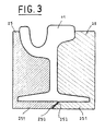
- La figure 3 représente, à échelle agrandie, une variante d'exécution d'un détail de la figure 2 ;
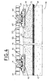
- La figure 4 est une vue en coupe semblable à celle de la figure 2, mais illustrant une deuxième forme de réalisation du système de support de rails suivant l'invention ;
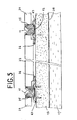
- La figure 5 illustre une troisième forme de réalisation du système de support de rails suivant l'invention ;
- La figure 6 illustre un exemple de dispositif de fixation de rail ;
- La figure 7 illustre une quatrième forme de réalisation du système de support de rails suivant l'invention ;
- La figure 8 illustre un dispositif de mise en précontrainte d'un rail dans le système de support suivant l'invention ;
- La figure 9 représente schématiquement un banc d'essai permettant d'analyser le comportement statique et dynamique d'une voie ferrée en tenant compte des charges par essieu et de la masse non suspendue du bogie.
- Figure 1 illustrates the transmission of acoustic and vibration waves from a tramway track to neighboring buildings;
- Figure 2 is a cross-sectional view of a section of railroad track, installed with an embodiment of the rail support system according to the invention;
- Figure 3 shows, on an enlarged scale, an alternative embodiment of a detail of Figure 2;
- Figure 4 is a sectional view similar to that of Figure 2, but illustrating a second embodiment of the rail support system according to the invention;
- FIG. 5 illustrates a third embodiment of the rail support system according to the invention;
- FIG. 6 illustrates an example of a rail fixing device;
- FIG. 7 illustrates a fourth embodiment of the rail support system according to the invention;
- FIG. 8 illustrates a device for prestressing a rail in the support system according to the invention;
- FIG. 9 schematically represents a test bench making it possible to analyze the static and dynamic behavior of a railroad track by taking account of the axle loads and the unsprung mass of the bogie.
Dans les dessins, une même référence désigne un élément identique ou un élément similaire ou équivalent. Les modes d'exécution illustrés dans ces dessins sont donnés à titre d'exemples non limitatifs. Des variantes d'exécution sont possibles selon les desiderata particuliers dans chaque cas.In the drawings, the same reference designates an identical element or a similar or equivalent element. The embodiments illustrated in these drawings are given by way of nonlimiting examples. Variants of execution are possible according to the particular desiderata in each case.
Se reportant à la figure 2, on voit représentés deux rails 11 d'une voie ferrée pour tramway posée conformément à l'invention. Dans cet exemple de mode de réalisation, chacun des rails 11 est fixé sur des traverses 13 avec interposition d'une semelle 12 qui peut être rigide ou constituée d'une matière antivibratoire en fonction des charges prévues par essieu. Les traverses 13 des deux rails sont ancrées dans une dalle radier 15 en béton armé, préfabriquée ou coulée sur le site.Referring to Figure 2, there are shown two
A cet effet, la dalle radier présente des cuvettes pour recevoir la partie inférieure des traverses. La dalle radier 15 repose sur une couche de sable stabilisé 17 posée sur le fond de coffre (sol) 19. Sur la couche de sable stabilisé 17 est de préférence posée une couche drainante 16 destinée à drainer les infiltrations d'eau vers des tuyaux drainants 18 disposés à intervalles le long de la voie avec un diamètre et un écartement qui sont fonction de la situation géographique de la voirie. La dalle radier assure la stabilité de l'installation. Eventuellement, une couche de matière antivibratoire peut encore être disposée entre le lit de sable stabilisé et la dalle radier.To this end, the slab slab has bowls to receive the lower part of the sleepers. The
Le long des côtés extérieurs des rails 11 s'étendent des dalles ou poutres de voirie 21 qui reposent partiellement sur les traverses 13 des deux rails et sont scellées aux bords latéraux 23 de la dalle radier 15. Entre les rails 11 sont disposées des dalles de voirie préfabriquées 22 qui reposent sur des appuis de réglage de niveau 24 constitués d'appuis résilients très rigide ou d'appuis antivibratoires définis selon l'environnement et la circulation prévue sur la voirie. Une fourrure de fermeture longitudinale 26 en béton coulé est insérée sous les bords latéraux des dalles 22.Along the outer sides of the
Les espaces entre les rails 11 et les dalles de voirie 21 et 22 sont remplis par des éléments de séparation 25 préfabriqués ou constitués d'un produit de remplissage étanche et souple dont les rigidités statique et dynamique sont choisies en fonction de la semelle antivibratoire sous le rail.The spaces between the
Plus spécifiquement, les rigidités statique et dynamique des éléments de séparation 25 sont choisies de manière que les rigidités statique et dynamique de l'ensemble du support soient inférieures à celles des semelles placées sous les rails. Les rails se trouvent ainsi totalement indépendants de la voirie, ce qui a pour conséquence de réduire considérablement la transmission des vibrations vers les fondations des immeubles avoisinants en même temps qu'est assurée une étanchéité le long des rails.More specifically, the static and dynamic stiffnesses of the separating
Le vide entre la dalle de voirie 22 et la dalle radier 15 est de préférence rempli par injection d'un produit de remplissage approprié 28 choisi en fonction du degré d'isolation requis par l'environnement.The vacuum between the
La figure 3 montre, à échelle agrandie, une variante d'exécution pour les éléments de séparation 25 qui séparent les rails des dalles de voirie. Dans ce mode d'exécution, les deux éléments de séparation enveloppent le patin d'un rail 11, chaque élément présentant une partie inférieure 251 qui s'étend sous une partie au moins du patin. Les parties inférieures des deux éléments 25 sont jointives suivant des faces 252 qui s'étendent dans un plan oblique par rapport à la base du patin du rail 11. De cette manière, la laitance qui se produit lors de la coulée de béton lors de la mise en place des dalles de voirie 22 entre les rails de la voie ne peut s'infiltrer et remonter dans l'interstice entre les faces coopérantes 252, ce qui évite la formation d'un pont de béton qui transmettrait les vibrations du rail vers les fondations comme cela se produit lorsque les faces d'extrémité de la partie inférieure sont verticales. De plus, la jonction parfaite entre les parties inférieures des éléments de séparation sous le patin du rail stabilise l'assise du rail.FIG. 3 shows, on an enlarged scale, an alternative embodiment for the
Dans un mode de réalisation avantageux, les appuis successifs le long de la voie ferrée sont réalisés de manière à constituer alternativement un appui relativement rigide et un appui relativement souple. Les avantages de ce mode de réalisation ont été exposés ci-avant.In an advantageous embodiment, the successive supports along the track are made so as to alternately constitute a support relatively rigid and relatively flexible support. The advantages of this embodiment have been explained above.
Comme indiqué plus haut, les rails peuvent être fixés de différentes manières selon l'encombrement ou la technique souhaitée dans l'application envisagée ou encore selon le degré de protection de l'environnement que le maître de l'ouvrage veut assurer.As indicated above, the rails can be fixed in different ways depending on the size or the technique desired in the envisaged application or according to the degree of environmental protection that the owner wants to ensure.
La figure 4 illustre un cas où le rail 11 est fixé sur des selles 33 scellées dans la dalle radier 15, à l'aide d'un mortier d'époxy, par exemple. Sur chaque selle le rail repose sur une semelle 12 rigide ou antivibratoire. La référence 31 désigne un dispositif de fixation de rail à éclisses. Sur le sable stabilisé 17 sont disposées, à titre d'exemple, une couche drainante 35 et un tapis d'isolation antivibratoire 37. Conformément à l'invention, les espaces entre chaque rail 11 et les dalles de voirie 21 et 22 sont remplis par des éléments de séparation 25 en matière ayant des rigidités statique et dynamique prédéterminées.FIG. 4 illustrates a case where the
La figure 5 illustre un cas où le rail 11 est également fixé sur des selles 43 mais où celles-ci se trouvent fixées à la dalle radier 15 au moyen de boulons. La dalle de voirie 22 repose ici sur des appuis de mise à niveau 24 qui peuvent être rigides ou être constitués d'une matière antivibratoire. On notera qu'un coussin antivibratoire peut être interposé entre chaque selle et la dalle radier. Le vide entre la dalle de voirie et la dalle radier peut le cas échéant être rempli par injection d'un produit de remplissage approprié.FIG. 5 illustrates a case where the
La figure 6 montre en particulier un exemple d'attache 47 pour fixer le patin d'un rail 11 sur une selle 43 avec une coiffe de protection 48 pour l'attache. Le patin du rail repose sur une semelle antivibratoire 12.FIG. 6 shows in particular an example of
La figure 7 illustre la fixation d'un rail 11 sur une selle 43 qui est elle-même fixée à la dalle radier 15 au moyen d'un dispositif de fixation réglable 41 appliquant une précontrainte réglable à la semelle antivibratoire 42 disposée sous la selle 43. Ce dispositif de fixation assure une isolation antivibratoire à basse fréquence de résonance. Le dispositif de fixation illustré comprend un ressort de précontrainte 45 maintenu entre deux rondelles de butée autour d'une tige filetée 44. Le ressort 45 est comprimé par l'écrou de serrage 46 qui ajuste l'effort de précontrainte. Le dispositif de fixation peut aussi comporter deux ressorts ayant des rigidités différentes et maintenus entre deux rondelles autour de la tige filetée 44, les ressorts étant comprimés par l'écrou de serrage 46 qui ajuste l'effort de précontrainte.FIG. 7 illustrates the fixing of a
La figure 8 illustre un agencement maintenant localement l'âme du rail 11 et lui appliquant une précontrainte réglable qui confère à la voie un comportement statique et dynamique assurant une isolation parfaite des vibrations. L'agencement de précontrainte comprend une tige filetée 51 traversant l'âme du rail 11 et s'étendant entre deux butées résilientes 53 appliquées contre les faces latérales d'une rainure 14 ménagée dans la dalle radier 15. Des ressorts 52 sont disposés autour des extrémités de la tige 51 et sont serrés de manière réglable contre les butées résilientes 53 par des écrous 54. L'âme du rail est maintenue entre deux écrous 56 calés sur la tige 51. Le réglage des écrous 54 et 56 ajuste la précontrainte appliquée au rail. Après réglage des écrous, la rainure 14 est remplie d'une matière de remplissage dont les caractéristiques sont déterminées en fonction de la raideur de la semelle antivibratoire 12 sur laquelle repose le rail 11 et en fonction de la précontrainte appliquée au rail. Les caractéristiques des ressorts 52 sont choisies en fonction des charges par essieu et de la largeur de la rainure 14. Conformément à l'invention, les espaces entre chaque rail 11 et les dalles de voirie 21 et 22 sont remplis par des éléments de séparation 25 en matière ayant des rigidités statique et dynamique prédéterminées.FIG. 8 illustrates an arrangement locally maintaining the core of the
Dans une voie ferrée montée sur des appuis munis d'éléments antivibratoires, en particulier lorsque les éléments antivibratoires sont disposés à différents niveaux, les performances d'isolation acoustique et antivibratoire sont liées à une combinaison optimale des caractéristiques des éléments intervenants dans la réalisation des dispositifs antivibratoires. Afin de mettre au point le système de support adéquat en fonction des conditions d'exploitation réelles, c'est-à-dire des caractéristiques du sol du point de vue de la transmissibilité des ondes vibratoires vers l'environnement, et en fonction du niveau de performances d'isolation souhaité, il est essentiel de pouvoir mesurer et analyser correctement à la fois le comportement statique et le comportement dynamique des ensembles roue / rail / support d'une voie ferrée.In a railway track mounted on supports provided with anti-vibration elements, in particular when the anti-vibration elements are arranged at different levels, the acoustic and anti-vibration insulation performances are linked to an optimal combination of the characteristics of the elements involved in the production of the devices vibration. In order to develop the appropriate support system according to the real operating conditions, that is to say the characteristics of the soil from the point of view of the transmissibility of the vibratory waves to the environment, and according to the level insulation performance, it is essential to be able to measure and correctly analyze both the static and dynamic behavior of the wheel / rail / support assemblies of a railroad track.
Dans ce but, les inventeurs ont conçu un procédé de mesure par lequel les effets de la charge statique totale appliquée à un essieu d'un véhicule devant circuler sur une voie ferrée sont découplés de l'équivalent de la masse non suspendue d'un bogie. La mise en oeuvre de ce procédé peut être réalisée, par exemple, à l'aide d'un banc d'essai tel que représenté schématiquement à la figure 9.To this end, the inventors have devised a measurement method by which the effects of the total static load applied to an axle of a vehicle having to travel on a railway track are decoupled from the equivalent of the unsprung mass of a bogie. The implementation of this method can be carried out, for example, using a test bench as shown diagrammatically in FIG. 9.
La Figure 9 montre schématiquement une vue longitudinale d'un exemple de mode de réalisation. Le banc d'essai comprend un bâti sur lequel sont montés à espacement régulier des ressorts à basse fréquence de résonance 62. Sur ces ressorts sont fixés des appuis antivibratoires 61 servant à porter un tronçon de voie ferrée à tester. Un chariot mobile 63 est monté sur des roues dont l'écartement est réglable en fonction de l'écartement des essieux de bogie d'un véhicule. La masse du chariot 63 simule la masse non suspendue fixée à l'essieu d'un véhicule devant circuler sur la voie ferrée. Sur le chariot 63 est monté une cellule de charge 64 constituée d'un plateau 66 supporté par un dispositif comprimable 65. Sur le plateau 66 est fixé un vérin hydraulique 67 permettant d'appliquer une charge statique variable représentant le poids d'un véhicule sur un essieu. Les appuis 61 sont réalisés avec des raideurs statiques et dynamiques choisies en fonction des conditions d'exploitation réelles et du niveau de performances souhaité. Par exemple, dans le cas où l'on souhaite optimiser l'isolement antivibratoire et limiter la déflexion du rail, les appuis 61 seront réalisés avec des raideurs alternées de manière à être alternativement un appui relativement rigide R et un appui relativement souple S.Figure 9 schematically shows a longitudinal view of an exemplary embodiment. The test bench comprises a frame on which are mounted at regular spacing springs with
Pour vérifier le comportement antivibratoire d'une voie ferrée particulière, on choisit des appuis antivibratoires ayant des raideurs statiques et dynamiques calculées pour tenir compte des conditions d'exploitation réelles de la voie ferrée et on les fixe sur les ressorts 62. Sur les appuis antivibratoires choisis 61 est alors disposé un tronçon de voie et sur celui-ci on place le chariot 63 après en avoir ajusté l'écartement des roues pour correspondre à l'écartement réel des essieux d'un bogie de véhicule roulant réel. Des capteurs connectés à des appareils de mesure et/ou d'enregistrement classiques sont ensuite mis en place d'une manière connue en soi pour mesurer les performances statiques et dynamiques de la voie : fréquence propre, déflexions statiques au droit des appuis, amortissement des vibrations des rails.To verify the anti-vibration behavior of a particular railroad, anti-vibration supports are chosen having static and dynamic stiffness calculated to take into account the actual operating conditions of the railway and they are fixed on the
En appliquant à la cellule de charge 64, une charge par paliers allant de 0 à 250 kN, par exemple, et en déplaçant le chariot le long du tronçon de voie ferrée, il est possible de relever la déflexion statique du rail au droit de chaque appui.By applying to load cell 64, a load in stages ranging from 0 to 250 kN, for example, and by moving the carriage along the section of track, it is possible to detect the static deflection of the rail to the right of each support.
En appliquant à la cellule de charge 64 une charge statique par paliers et par impulsions de chocs ou impulsions vibratoires et en déplaçant le chariot le long du tronçon de voie ferrée, on peut relever la fréquence propre du système de voie, les déflexions au droit des supports et l'amortissement des vibrations des rails au droit de chaque appui. Les analyses ainsi effectuées permettent au concepteur d'une voie ferrée à installer de déterminer de manière optimale les particularités des éléments d'isolation acoustique et antivibratoire à incorporer dans le système de support de la voie ferrée afin d'optimiser l'isolation acoustique et antivibratoire et réduire la transmission des ondes vibratoires vers l'environnement.By applying a static load to the load cell 64 in stages and by shock pulses or vibratory pulses and by moving the carriage along the section of track, the natural frequency of the track system can be noted, the deflections in line with the supports and vibration damping of the rails to the right of each support. The analyzes thus carried out allow the designer of a railway track to be installed to determine in an optimal manner the particularities of the acoustic and anti-vibration insulation elements to be incorporated in the railroad support system in order to optimize the acoustic and anti-vibration insulation. and reduce the transmission of vibration waves to the environment.
Claims (18)
Applications Claiming Priority (2)
| Application Number | Priority Date | Filing Date | Title |
|---|---|---|---|
| BE2001/0502A BE1014311A5 (en) | 2001-07-25 | 2001-07-25 | Rail support system for railway in highways and analysis system for such a rail. |
| BE200100502 | 2001-07-25 |
Publications (2)
| Publication Number | Publication Date |
|---|---|
| EP1279770A2 true EP1279770A2 (en) | 2003-01-29 |
| EP1279770A3 EP1279770A3 (en) | 2003-03-05 |
Family
ID=3897065
Family Applications (1)
| Application Number | Title | Priority Date | Filing Date |
|---|---|---|---|
| EP02447141A Withdrawn EP1279770A3 (en) | 2001-07-25 | 2002-07-23 | Railway support system for rails |
Country Status (2)
| Country | Link |
|---|---|
| EP (1) | EP1279770A3 (en) |
| BE (1) | BE1014311A5 (en) |
Cited By (7)
| Publication number | Priority date | Publication date | Assignee | Title |
|---|---|---|---|---|
| EP1460175A1 (en) * | 2003-03-17 | 2004-09-22 | Régie Autonome des Transports Parisiens | Method for laying a traffic or railway platform and thus obtained platform |
| WO2005124027A1 (en) * | 2004-06-22 | 2005-12-29 | Gmundner Fertigteile Gesellschaft M.B.H. & Co. Kg. | Ladder sleeper track |
| EP1830002A1 (en) * | 2006-03-02 | 2007-09-05 | BTE Stelcon Deutschland GmbH | Track structure adapted for tramways |
| EP2295635A3 (en) * | 2009-08-14 | 2013-03-13 | edilon)(sedra GmbH | Rail bearing with covers for flexible bus section and method for producing same |
| FR2993582A1 (en) * | 2012-07-17 | 2014-01-24 | Regie Autonome Transports | Method for installing track in railway track network for e.g. underground railway train, involves installing slab on support elements by aligning slab in two directions such that slab is held on elements for passage of rail vehicle on rails |
| CN111395072A (en) * | 2020-03-25 | 2020-07-10 | 江苏锡沂钢模有限公司 | High-speed railway sleeper of horizontal vertical vibration of water resistance |
| CN113756138A (en) * | 2021-10-08 | 2021-12-07 | 重庆交通职业学院 | Anti-settling subway rail |
Citations (6)
| Publication number | Priority date | Publication date | Assignee | Title |
|---|---|---|---|---|
| WO1997013037A1 (en) * | 1995-10-03 | 1997-04-10 | Gmundner Fertigteile Gesellschaft Mbh & Co. Kg | Level crossing |
| NL1001542C2 (en) * | 1995-10-31 | 1997-05-02 | Stichting Geluidarme Spoorbrug | Construction method of railway |
| US5756903A (en) * | 1995-11-22 | 1998-05-26 | Holland Company | Track strength testing vehicle with a loaded gage axle and loaded gage axle apparatus |
| WO1998051863A1 (en) * | 1997-05-13 | 1998-11-19 | Mecno-Rail S.R.L. | Track superstructure, in particular for tramway, tram-railway and underground railway lines |
| DE19822178A1 (en) * | 1998-05-16 | 1999-12-02 | Weiss Gmbh & Co Leonhard | Ballastless railway track with rails set in endless strip of reinforced concrete |
| DE29918842U1 (en) * | 1998-10-26 | 2000-02-17 | Dresdner Verkehrsbetriebe Ag | Track superstructure for trams, in particular in a carriageway for road vehicles |
-
2001
- 2001-07-25 BE BE2001/0502A patent/BE1014311A5/en not_active IP Right Cessation
-
2002
- 2002-07-23 EP EP02447141A patent/EP1279770A3/en not_active Withdrawn
Patent Citations (6)
| Publication number | Priority date | Publication date | Assignee | Title |
|---|---|---|---|---|
| WO1997013037A1 (en) * | 1995-10-03 | 1997-04-10 | Gmundner Fertigteile Gesellschaft Mbh & Co. Kg | Level crossing |
| NL1001542C2 (en) * | 1995-10-31 | 1997-05-02 | Stichting Geluidarme Spoorbrug | Construction method of railway |
| US5756903A (en) * | 1995-11-22 | 1998-05-26 | Holland Company | Track strength testing vehicle with a loaded gage axle and loaded gage axle apparatus |
| WO1998051863A1 (en) * | 1997-05-13 | 1998-11-19 | Mecno-Rail S.R.L. | Track superstructure, in particular for tramway, tram-railway and underground railway lines |
| DE19822178A1 (en) * | 1998-05-16 | 1999-12-02 | Weiss Gmbh & Co Leonhard | Ballastless railway track with rails set in endless strip of reinforced concrete |
| DE29918842U1 (en) * | 1998-10-26 | 2000-02-17 | Dresdner Verkehrsbetriebe Ag | Track superstructure for trams, in particular in a carriageway for road vehicles |
Non-Patent Citations (1)
| Title |
|---|
| HAMMARLUND S ET AL: "GOOSE HILL MEASUREMENTS CONFIRM X2000'S LOW DYNAMIC TRACK FORCES" RAILWAY GAZETTE INTERNATIONAL, IPC TRANSPORT PRESS LTD. LONDON, GB, vol. 150, no. 7, 1 juillet 1994 (1994-07-01), pages 439,441-444, XP000452232 ISSN: 0373-5346 * |
Cited By (8)
| Publication number | Priority date | Publication date | Assignee | Title |
|---|---|---|---|---|
| EP1460175A1 (en) * | 2003-03-17 | 2004-09-22 | Régie Autonome des Transports Parisiens | Method for laying a traffic or railway platform and thus obtained platform |
| FR2852614A1 (en) * | 2003-03-17 | 2004-09-24 | Regie Autonome Transports | METHOD FOR LAYING A RAIL AND ROAD TRAFFIC PLATFORM, AND PLATFORM OBTAINED BY THIS PROCESS |
| WO2005124027A1 (en) * | 2004-06-22 | 2005-12-29 | Gmundner Fertigteile Gesellschaft M.B.H. & Co. Kg. | Ladder sleeper track |
| EP1830002A1 (en) * | 2006-03-02 | 2007-09-05 | BTE Stelcon Deutschland GmbH | Track structure adapted for tramways |
| EP2295635A3 (en) * | 2009-08-14 | 2013-03-13 | edilon)(sedra GmbH | Rail bearing with covers for flexible bus section and method for producing same |
| FR2993582A1 (en) * | 2012-07-17 | 2014-01-24 | Regie Autonome Transports | Method for installing track in railway track network for e.g. underground railway train, involves installing slab on support elements by aligning slab in two directions such that slab is held on elements for passage of rail vehicle on rails |
| CN111395072A (en) * | 2020-03-25 | 2020-07-10 | 江苏锡沂钢模有限公司 | High-speed railway sleeper of horizontal vertical vibration of water resistance |
| CN113756138A (en) * | 2021-10-08 | 2021-12-07 | 重庆交通职业学院 | Anti-settling subway rail |
Also Published As
| Publication number | Publication date |
|---|---|
| BE1014311A5 (en) | 2003-08-05 |
| EP1279770A3 (en) | 2003-03-05 |
Similar Documents
| Publication | Publication Date | Title |
|---|---|---|
| CA2598637C (en) | Railroad tie | |
| Nelson | Recent developments in ground-borne noise and vibration control | |
| Wilson et al. | Control of ground-borne noise and vibration | |
| Ouakka et al. | Railway ground vibration and mitigation measures: benchmarking of best practices | |
| CA2987083A1 (en) | Support for a panel of a section of guided transport track | |
| US20010023897A1 (en) | Rail support | |
| EP1279770A2 (en) | Railway support system for rails | |
| BE1017257A5 (en) | SEAT WITH REDUCED VIBRATION LEVEL FOR RAILWAY. | |
| KR101815652B1 (en) | Low vibration railway building and its construction method | |
| AU2006212686B2 (en) | Level crossing | |
| KR20180056255A (en) | Floating slab track using steel beam to resist rolling under the eccentric vehicular load | |
| Butorina et al. | Reduction of vibroacoustic effect of high-speed trains | |
| BE1014836A6 (en) | Test bench for measuring static and dynamic behavior of rail track comprises frame carrying low resonance frequency springs on which anti-vibration supports are fixed serving to carry track section on which carriage runs | |
| EP1251204B1 (en) | Vibration insulating system for railway tracks | |
| BE1015814A5 (en) | Track railway system installation and traverse to such a system. | |
| KR100613412B1 (en) | Method of repairing a vibration proof sleeper of the concrete ballast | |
| Esveld | Track structures in an urban environment | |
| Wang et al. | Railway bridge noise control with resilient baseplates | |
| FR2901814A1 (en) | Railway track assembly for railway level crossing, has protection bars on both sides of continuous welded rails, and fixation system fixing rails on support element, where system transmits internal longitudinal efforts of rails to element | |
| BE1009576A6 (en) | Rail laying system | |
| WO2000046448A1 (en) | Support device for railway track rails | |
| EP1118711B1 (en) | Supporting device for a rail of railway track | |
| JPH06248606A (en) | Vibration-proof track | |
| BE1008607A3 (en) | Choker VIBRATIONS FOR RAILWAY TRACK CONSTRUCTION OR OTHER SUPPORT FOR TRAFFIC. | |
| da Paiva et al. | Evaluation between two Brazilian railway tracks |
Legal Events
| Date | Code | Title | Description |
|---|---|---|---|
| PUAI | Public reference made under article 153(3) epc to a published international application that has entered the european phase |
Free format text: ORIGINAL CODE: 0009012 |
|
| PUAL | Search report despatched |
Free format text: ORIGINAL CODE: 0009013 |
|
| AK | Designated contracting states |
Designated state(s): AT BE BG CH CY CZ DE DK EE ES FI FR GB GR IE IT LI LU MC NL PT SE SK TR |
|
| AX | Request for extension of the european patent |
Extension state: AL LT LV MK RO SI |
|
| AK | Designated contracting states |
Kind code of ref document: A3 Designated state(s): AT BE BG CH CY CZ DE DK EE ES FI FR GB GR IE IT LI LU MC NL PT SE SK TR Designated state(s): AT BE BG CH CY CZ DE DK EE ES FI FR GB GR IE IT LI LU MC NL PT SE SK TR |
|
| AX | Request for extension of the european patent |
Extension state: AL LT LV MK RO SI |
|
| 17P | Request for examination filed |
Effective date: 20030808 |
|
| AKX | Designation fees paid |
Designated state(s): AT BE BG CH CY CZ DE DK EE ES FI FR GB GR IE IT LI LU MC NL PT SE SK TR |
|
| 17Q | First examination report despatched |
Effective date: 20041013 |
|
| STAA | Information on the status of an ep patent application or granted ep patent |
Free format text: STATUS: THE APPLICATION IS DEEMED TO BE WITHDRAWN |
|
| 18D | Application deemed to be withdrawn |
Effective date: 20050224 |