EP1829645B1 - Schleifverfahren zum Beranden einer Linse - Google Patents
Schleifverfahren zum Beranden einer Linse Download PDFInfo
- Publication number
- EP1829645B1 EP1829645B1 EP07011724A EP07011724A EP1829645B1 EP 1829645 B1 EP1829645 B1 EP 1829645B1 EP 07011724 A EP07011724 A EP 07011724A EP 07011724 A EP07011724 A EP 07011724A EP 1829645 B1 EP1829645 B1 EP 1829645B1
- Authority
- EP
- European Patent Office
- Prior art keywords
- lens
- adhesive
- edging
- tape
- adhesive tape
- Prior art date
- Legal status (The legal status is an assumption and is not a legal conclusion. Google has not performed a legal analysis and makes no representation as to the accuracy of the status listed.)
- Expired - Lifetime
Links
- 238000007688 edging Methods 0.000 title claims description 137
- 238000000034 method Methods 0.000 title claims description 55
- 239000002390 adhesive tape Substances 0.000 claims description 142
- 239000000853 adhesive Substances 0.000 claims description 79
- 230000001070 adhesive effect Effects 0.000 claims description 79
- 238000012360 testing method Methods 0.000 claims description 47
- 239000012790 adhesive layer Substances 0.000 claims description 46
- 238000003754 machining Methods 0.000 claims description 42
- 239000000758 substrate Substances 0.000 claims description 41
- -1 polyethylene terephthalate Polymers 0.000 claims description 39
- 230000003373 anti-fouling effect Effects 0.000 claims description 37
- 239000010410 layer Substances 0.000 claims description 34
- 238000010998 test method Methods 0.000 claims description 28
- YCKRFDGAMUMZLT-UHFFFAOYSA-N Fluorine atom Chemical compound [F] YCKRFDGAMUMZLT-UHFFFAOYSA-N 0.000 claims description 21
- 229910052731 fluorine Inorganic materials 0.000 claims description 21
- 239000011737 fluorine Substances 0.000 claims description 21
- 229920000139 polyethylene terephthalate Polymers 0.000 claims description 20
- 239000005020 polyethylene terephthalate Substances 0.000 claims description 20
- 229910000077 silane Inorganic materials 0.000 claims description 19
- 239000003795 chemical substances by application Substances 0.000 claims description 15
- 238000005259 measurement Methods 0.000 claims description 14
- 229920001296 polysiloxane Polymers 0.000 claims description 12
- 238000007718 adhesive strength test Methods 0.000 claims description 10
- 238000004381 surface treatment Methods 0.000 claims description 10
- 229910052739 hydrogen Chemical group 0.000 claims description 9
- 239000001257 hydrogen Chemical group 0.000 claims description 9
- UFHFLCQGNIYNRP-UHFFFAOYSA-N Hydrogen Chemical group [H][H] UFHFLCQGNIYNRP-UHFFFAOYSA-N 0.000 claims description 5
- 125000004432 carbon atom Chemical group C* 0.000 claims description 5
- 125000004435 hydrogen atom Chemical group [H]* 0.000 claims description 4
- 125000000217 alkyl group Chemical group 0.000 claims description 3
- 125000000962 organic group Chemical group 0.000 claims description 3
- 125000005010 perfluoroalkyl group Chemical group 0.000 claims description 3
- 125000002023 trifluoromethyl group Chemical group FC(F)(F)* 0.000 claims description 3
- ZCYVEMRRCGMTRW-UHFFFAOYSA-N 7553-56-2 Chemical group [I] ZCYVEMRRCGMTRW-UHFFFAOYSA-N 0.000 claims description 2
- 229910052740 iodine Inorganic materials 0.000 claims description 2
- 239000011630 iodine Substances 0.000 claims description 2
- 210000000887 face Anatomy 0.000 description 11
- 239000004575 stone Substances 0.000 description 11
- 239000011248 coating agent Substances 0.000 description 9
- 238000000576 coating method Methods 0.000 description 9
- 238000003825 pressing Methods 0.000 description 8
- 229920005989 resin Polymers 0.000 description 7
- 239000011347 resin Substances 0.000 description 7
- 150000001875 compounds Chemical class 0.000 description 6
- 238000010586 diagram Methods 0.000 description 6
- 239000000463 material Substances 0.000 description 6
- 230000003287 optical effect Effects 0.000 description 5
- 230000001603 reducing effect Effects 0.000 description 5
- 239000004698 Polyethylene Substances 0.000 description 4
- 238000011156 evaluation Methods 0.000 description 4
- 239000002985 plastic film Substances 0.000 description 4
- 230000000750 progressive effect Effects 0.000 description 4
- KFZMGEQAYNKOFK-UHFFFAOYSA-N Isopropanol Chemical compound CC(C)O KFZMGEQAYNKOFK-UHFFFAOYSA-N 0.000 description 3
- 229910000831 Steel Inorganic materials 0.000 description 3
- NIXOWILDQLNWCW-UHFFFAOYSA-N acrylic acid group Chemical group C(C=C)(=O)O NIXOWILDQLNWCW-UHFFFAOYSA-N 0.000 description 3
- 125000001931 aliphatic group Chemical group 0.000 description 3
- 238000004140 cleaning Methods 0.000 description 3
- 230000002349 favourable effect Effects 0.000 description 3
- 239000007788 liquid Substances 0.000 description 3
- 239000003960 organic solvent Substances 0.000 description 3
- 229920003023 plastic Polymers 0.000 description 3
- 239000004033 plastic Substances 0.000 description 3
- 229920000573 polyethylene Polymers 0.000 description 3
- 239000010959 steel Substances 0.000 description 3
- 238000009864 tensile test Methods 0.000 description 3
- CSCPPACGZOOCGX-UHFFFAOYSA-N Acetone Chemical compound CC(C)=O CSCPPACGZOOCGX-UHFFFAOYSA-N 0.000 description 2
- LFQSCWFLJHTTHZ-UHFFFAOYSA-N Ethanol Chemical compound CCO LFQSCWFLJHTTHZ-UHFFFAOYSA-N 0.000 description 2
- 239000003522 acrylic cement Substances 0.000 description 2
- 201000009310 astigmatism Diseases 0.000 description 2
- SYFOAKAXGNMQAX-UHFFFAOYSA-N bis(prop-2-enyl) carbonate;2-(2-hydroxyethoxy)ethanol Chemical compound OCCOCCO.C=CCOC(=O)OCC=C SYFOAKAXGNMQAX-UHFFFAOYSA-N 0.000 description 2
- 229920001971 elastomer Polymers 0.000 description 2
- 229920006255 plastic film Polymers 0.000 description 2
- 239000005060 rubber Substances 0.000 description 2
- 229910001220 stainless steel Inorganic materials 0.000 description 2
- 239000010935 stainless steel Substances 0.000 description 2
- 238000001771 vacuum deposition Methods 0.000 description 2
- QIROQPWSJUXOJC-UHFFFAOYSA-N 1,1,2,2,3,3,4,4,5,5,6-undecafluoro-6-(trifluoromethyl)cyclohexane Chemical compound FC(F)(F)C1(F)C(F)(F)C(F)(F)C(F)(F)C(F)(F)C1(F)F QIROQPWSJUXOJC-UHFFFAOYSA-N 0.000 description 1
- 239000004925 Acrylic resin Substances 0.000 description 1
- 229920000178 Acrylic resin Polymers 0.000 description 1
- ZAMOUSCENKQFHK-UHFFFAOYSA-N Chlorine atom Chemical compound [Cl] ZAMOUSCENKQFHK-UHFFFAOYSA-N 0.000 description 1
- 229920001875 Ebonite Polymers 0.000 description 1
- 244000043261 Hevea brasiliensis Species 0.000 description 1
- 230000005483 Hooke's law Effects 0.000 description 1
- 239000004952 Polyamide Substances 0.000 description 1
- 239000004642 Polyimide Substances 0.000 description 1
- 229920002367 Polyisobutene Polymers 0.000 description 1
- 239000004743 Polypropylene Substances 0.000 description 1
- 239000004793 Polystyrene Substances 0.000 description 1
- 125000002029 aromatic hydrocarbon group Chemical group 0.000 description 1
- 239000012298 atmosphere Substances 0.000 description 1
- 210000005252 bulbus oculi Anatomy 0.000 description 1
- 229920005549 butyl rubber Polymers 0.000 description 1
- 229920002301 cellulose acetate Polymers 0.000 description 1
- 229910052801 chlorine Inorganic materials 0.000 description 1
- 239000000460 chlorine Substances 0.000 description 1
- 238000007796 conventional method Methods 0.000 description 1
- 230000010485 coping Effects 0.000 description 1
- 239000002537 cosmetic Substances 0.000 description 1
- 238000007865 diluting Methods 0.000 description 1
- 238000007598 dipping method Methods 0.000 description 1
- 238000007606 doctor blade method Methods 0.000 description 1
- 230000000694 effects Effects 0.000 description 1
- 239000003822 epoxy resin Substances 0.000 description 1
- 239000002657 fibrous material Substances 0.000 description 1
- 239000006260 foam Substances 0.000 description 1
- 239000011521 glass Substances 0.000 description 1
- 229910052736 halogen Inorganic materials 0.000 description 1
- 150000002367 halogens Chemical class 0.000 description 1
- 238000010438 heat treatment Methods 0.000 description 1
- 150000002430 hydrocarbons Chemical group 0.000 description 1
- 238000004519 manufacturing process Methods 0.000 description 1
- 230000005499 meniscus Effects 0.000 description 1
- 125000000956 methoxy group Chemical group [H]C([H])([H])O* 0.000 description 1
- 229920003052 natural elastomer Polymers 0.000 description 1
- 229920001194 natural rubber Polymers 0.000 description 1
- 229960004624 perflexane Drugs 0.000 description 1
- LOQGSOTUHASIHI-UHFFFAOYSA-N perfluoro-1,3-dimethylcyclohexane Chemical compound FC(F)(F)C1(F)C(F)(F)C(F)(F)C(F)(F)C(F)(C(F)(F)F)C1(F)F LOQGSOTUHASIHI-UHFFFAOYSA-N 0.000 description 1
- ZJIJAJXFLBMLCK-UHFFFAOYSA-N perfluorohexane Chemical compound FC(F)(F)C(F)(F)C(F)(F)C(F)(F)C(F)(F)C(F)(F)F ZJIJAJXFLBMLCK-UHFFFAOYSA-N 0.000 description 1
- 229920001084 poly(chloroprene) Polymers 0.000 description 1
- 229920002647 polyamide Polymers 0.000 description 1
- 229920000515 polycarbonate Polymers 0.000 description 1
- 239000004417 polycarbonate Substances 0.000 description 1
- 229920005668 polycarbonate resin Polymers 0.000 description 1
- 239000004431 polycarbonate resin Substances 0.000 description 1
- 229920000647 polyepoxide Polymers 0.000 description 1
- 229920000728 polyester Polymers 0.000 description 1
- 229920001721 polyimide Polymers 0.000 description 1
- 229920001195 polyisoprene Polymers 0.000 description 1
- 229920001155 polypropylene Polymers 0.000 description 1
- 229920002223 polystyrene Polymers 0.000 description 1
- 229920001343 polytetrafluoroethylene Polymers 0.000 description 1
- 229920005749 polyurethane resin Polymers 0.000 description 1
- 229920002689 polyvinyl acetate Polymers 0.000 description 1
- 239000011118 polyvinyl acetate Substances 0.000 description 1
- 239000004800 polyvinyl chloride Substances 0.000 description 1
- 229920000915 polyvinyl chloride Polymers 0.000 description 1
- 239000000843 powder Substances 0.000 description 1
- 230000002265 prevention Effects 0.000 description 1
- 238000012545 processing Methods 0.000 description 1
- 230000002250 progressing effect Effects 0.000 description 1
- 230000003014 reinforcing effect Effects 0.000 description 1
- 231100000241 scar Toxicity 0.000 description 1
- 239000002904 solvent Substances 0.000 description 1
- 239000007921 spray Substances 0.000 description 1
- 229920003048 styrene butadiene rubber Polymers 0.000 description 1
- 239000000454 talc Substances 0.000 description 1
- 229910052623 talc Inorganic materials 0.000 description 1
- 229920005992 thermoplastic resin Polymers 0.000 description 1
- 229920001187 thermosetting polymer Polymers 0.000 description 1
- 238000002834 transmittance Methods 0.000 description 1
- 125000000391 vinyl group Chemical group [H]C([*])=C([H])[H] 0.000 description 1
- 229920002554 vinyl polymer Polymers 0.000 description 1
- 238000011179 visual inspection Methods 0.000 description 1
Images


Classifications
-
- B—PERFORMING OPERATIONS; TRANSPORTING
- B24—GRINDING; POLISHING
- B24B—MACHINES, DEVICES, OR PROCESSES FOR GRINDING OR POLISHING; DRESSING OR CONDITIONING OF ABRADING SURFACES; FEEDING OF GRINDING, POLISHING, OR LAPPING AGENTS
- B24B9/00—Machines or devices designed for grinding edges or bevels on work or for removing burrs; Accessories therefor
- B24B9/02—Machines or devices designed for grinding edges or bevels on work or for removing burrs; Accessories therefor characterised by a special design with respect to properties of materials specific to articles to be ground
- B24B9/06—Machines or devices designed for grinding edges or bevels on work or for removing burrs; Accessories therefor characterised by a special design with respect to properties of materials specific to articles to be ground of non-metallic inorganic material, e.g. stone, ceramics, porcelain
- B24B9/08—Machines or devices designed for grinding edges or bevels on work or for removing burrs; Accessories therefor characterised by a special design with respect to properties of materials specific to articles to be ground of non-metallic inorganic material, e.g. stone, ceramics, porcelain of glass
- B24B9/14—Machines or devices designed for grinding edges or bevels on work or for removing burrs; Accessories therefor characterised by a special design with respect to properties of materials specific to articles to be ground of non-metallic inorganic material, e.g. stone, ceramics, porcelain of glass of optical work, e.g. lenses, prisms
-
- B—PERFORMING OPERATIONS; TRANSPORTING
- B24—GRINDING; POLISHING
- B24B—MACHINES, DEVICES, OR PROCESSES FOR GRINDING OR POLISHING; DRESSING OR CONDITIONING OF ABRADING SURFACES; FEEDING OF GRINDING, POLISHING, OR LAPPING AGENTS
- B24B13/00—Machines or devices designed for grinding or polishing optical surfaces on lenses or surfaces of similar shape on other work; Accessories therefor
- B24B13/005—Blocking means, chucks or the like; Alignment devices
-
- C—CHEMISTRY; METALLURGY
- C09—DYES; PAINTS; POLISHES; NATURAL RESINS; ADHESIVES; COMPOSITIONS NOT OTHERWISE PROVIDED FOR; APPLICATIONS OF MATERIALS NOT OTHERWISE PROVIDED FOR
- C09J—ADHESIVES; NON-MECHANICAL ASPECTS OF ADHESIVE PROCESSES IN GENERAL; ADHESIVE PROCESSES NOT PROVIDED FOR ELSEWHERE; USE OF MATERIALS AS ADHESIVES
- C09J7/00—Adhesives in the form of films or foils
- C09J7/10—Adhesives in the form of films or foils without carriers
-
- C—CHEMISTRY; METALLURGY
- C09—DYES; PAINTS; POLISHES; NATURAL RESINS; ADHESIVES; COMPOSITIONS NOT OTHERWISE PROVIDED FOR; APPLICATIONS OF MATERIALS NOT OTHERWISE PROVIDED FOR
- C09J—ADHESIVES; NON-MECHANICAL ASPECTS OF ADHESIVE PROCESSES IN GENERAL; ADHESIVE PROCESSES NOT PROVIDED FOR ELSEWHERE; USE OF MATERIALS AS ADHESIVES
- C09J7/00—Adhesives in the form of films or foils
- C09J7/30—Adhesives in the form of films or foils characterised by the adhesive composition
- C09J7/38—Pressure-sensitive adhesives [PSA]
-
- Y—GENERAL TAGGING OF NEW TECHNOLOGICAL DEVELOPMENTS; GENERAL TAGGING OF CROSS-SECTIONAL TECHNOLOGIES SPANNING OVER SEVERAL SECTIONS OF THE IPC; TECHNICAL SUBJECTS COVERED BY FORMER USPC CROSS-REFERENCE ART COLLECTIONS [XRACs] AND DIGESTS
- Y10—TECHNICAL SUBJECTS COVERED BY FORMER USPC
- Y10T—TECHNICAL SUBJECTS COVERED BY FORMER US CLASSIFICATION
- Y10T428/00—Stock material or miscellaneous articles
- Y10T428/28—Web or sheet containing structurally defined element or component and having an adhesive outermost layer
- Y10T428/2848—Three or more layers
Definitions
- Present invention relates to a lens edging method according to the preamble of claim 1.
- a lens edging method is known, for example, from US-A-6 074 290 .
- a reflection reducing coating is ordinarily formed on a surface of a lens, such as a spectacle lens.
- a stain derived from adherence of, for example, dirt from a hand, a fingerprint, perspiration, or cosmetic is conspicuous and it is hard to remove the stain.
- an antifouling layer has further been provided on the surface of the reflection reducing coating.
- a spectacle lens which has been subjected to a surface treatment with a fluorine-containing silane compound which is described in JP-A No. 9-258003 to form the antifouling layer is favorable in the antifouling property. Further, the effect thereof lasts long.
- the lens which has been subjected to the surface treatment with the fluorine-containing silane compound as described in the above publication, has an extremely small friction coefficient compared with that obtained by using a conventional surface treating agent. Therefore, the surface of the lens has such a characteristic as being too slippery. Due to this characteristic, a problem as described below occurs when the lens is subjected to edging.
- grinding a round spectacle lens to a shape in which the lens can be inserted in a spectacle frame, namely, so-called edging is performed. In the edging, firstly, a machining center of the spectacle lens is sucked and held by chucks of an edge-machining apparatus.
- the machining center of the spectacle lens is clamped by applying pressure from both sides of the lens.
- the edge of the spectacle lens is ground by a grinding stone while the spectacle lens is held by a frictional force. Since the surface of the lens held by the chucks has good slipperiness, when the lens is ground by a grinding stone, the tends to lens slip, due to such good slipperiness of the surface of the lens, by the grinding pressure of the grinding stone against the chucks to be out of position, namely, a so-called axial misalignment occurs. This causes a problem in that precise edging can not be performed.
- the present invention has been achieved and has an object to provide a technique capable of edging a lens on which an antifouling layer has been formed by using a fluorine-containing silane compound excellent in its antifouling effect.
- the present inventors have conducted a test by using a stainless steel plate as a test plate defined in an adhesive strength test of an adhesive tape as described in JIS Z 0237 "adhesive tape/adhesive sheet test method".
- a measurement value of the adhesive strength of the adhesive tape having an excellent adhesive strength and a measurement value of the adhesive strength of the adhesive tape having an inferior adhesive strength against the lens on which the antifouling layer has been provided.
- the present inventors have studied a method for distinguishing adhesive tapes having an excellent adhesive strength against a lens, on which the antifouling layer is formed by using the fluorine-containing silane compound, from others. Specifically, the present inventors have conducted a test of the adhesive strength of an adhesive tape by using a polyethylene terephthalate plate which has been subjected to a surface treatment by using a fluorine-modified silicone parting agent as a test plate. As a result, it has been found that, by using the latter plate rather than using the stainless steel plate as a test plate, a difference appears between a measurement value of adhesive tapes having an excellent adhesive strength and those having an inferior adhesive strength against the spectacle lens on which the antifouling layer has been provided.
- the adhesive tape has an adhesive strength of 4 gf or more in the adhesive strength test using this test plate, it has been found that the adhesive tape is favorably attached to the spectacle lens on which the antifouling layer is formed by using the fluorine-containing silane compound. Still further, when an adhesive tape having an adhesive strength of 4 gf or more is interposed between the chuck of the edge-machining apparatus and the lens, it has been found that edging can be performed without generating an axial misalignment.
- a method of holding the lens by applying pressure by the chuck of the edge-machining apparatus from both sides of the lens is adopted.
- the adhesive tape by attaching the adhesive tape to the concave face of the lens, it is not necessary to attach the adhesive tape on various types of layout marks which have been applied on the convex face of the lens. Accordingly, the edging can be performed without any fear of removing the layout marks.
- the adhesive tape is attached to the convex face of a progressing multifocal spectacle lens, in order to avoid a mark of a fitting point which has been applied, it is preferable to provide a through-hole in a center portion of the adhesive tape.
- the adhesive tape used in the present invention is an adhesive tape which is provided between a lens and at least one of a pair of chucks in an edge-machining apparatus and comprises an adhesive face for being in contact with the lens.
- a measurement value of the adhesive strength of the adhesive face is 4 gf (0.0392 N) or more when a polyethylene terephthalate plate whose surface has been treated with a fluorine-modified silicone parting agent is used as a test plate in an adhesive strength test method based on the 180°-peeling method as defined in JIS Z 0237 "adhesive tape/adhesive sheet test method".
- a through-hole is provided in a central portion of the adhesive tape according to the present invention.
- An edging method according to the present invention attaches an adhesive tape on an antifouling layer of a lens in which the antifouling layer is provided. Then, the lens is held by a pair of chucks such that the adhesive tape is interposed between the lens and at least one of the pair of chucks in an edge-machining apparatus. Thereafter, edging of the lens is performed by the edge-machining apparatus.
- the adhesive tape comprises an adhesive face for being in contact with the lens.
- a measurement value of an adhesive strength of the adhesive face is 4 gf (0.0392 N) or more when a polyethylene terephthalate plate whose surface has been treated with a fluorine-modified silicone parting agent is used as a test plate in an adhesive strength test method based on the 180°-peeling method as defined in JIS Z 0237 "adhesive tape/adhesive sheet test method".
- the antifouling layer is formed by using as a main component a fluorine-containing silane compound as represented by the following general formula (1): wherein R f represents a straight or branched perfluoroalkyl group having from 1 or more to 16 or less carbon atoms; X represents iodine or hydrogen; Y represents hydrogen or a lower alkyl group; Z represents fluorine or a trifluoromethyl group; R 1 represents a hydrolysable group; R 2 represents hydrogen or an inactive monovalent organic group; a, b, c, and d each individually represent an integer of from 0 or more to 200 or less; e represents 0 or 1; m and n each individually represent an integer of from 0 or more to 2 or less; and p represents an integer of from 1 or more to 10 or less.
- R f represents a straight or branched perfluoroalkyl group having from 1 or more to 16 or less carbon atoms
- X represents iodine or hydrogen
- the edging method comprises a step of attaching the adhesive tape to a concave face of the lens.
- the adhesive tape used in the present invention is an adhesive tape which is provided between a lens and at least one of a pair of chucks in an edge-machining apparatus and comprises an adhesive face for being in contact with the lens. And, when an adhesive strength of the adhesive face is measured based on a predetermined test method, the measurement value of the adhesive strength is 4 gf (0.0392 N) or more.
- the predetermined test method is basically same as an adhesive strength test method based on the 180°-peeling method as defined in JIS Z 0237 "adhesive tape/adhesive sheet test method", except for replacing the test plate used in the adhesive strength test method based on the 180°-peeling method as defined in JIS Z 0237 "adhesive tape/adhesive sheet test method” by a polyethylene terephthalate plate in which a surface treatment has been performed with a fluorine-modified silicone parting agent.
- Embodiments of an edging method according to the present invention are described below, but the present invention is by no means limited thereto.
- Edging of a spectacle lens is edge machining which grinds the edge of a round spectacle lens by a grinding stone such that the spectacle lens may be inserted in a spectacle frame. Therefore, the edging is also called "edge machining".
- the spectacle lens is a meniscus lens which has a convex face on the object side and a concave face on the eye ball side.
- FIG. 5 shows an edging method of a lens to be performed by using an edge-machining apparatus.
- the lens L is sandwiched under pressure from both sides of an optical axis of the lens by chucks 2, 3 of an edge-machining apparatus.
- a lens lock tape 4 is ordinarily attached to a convex face side of the lens L for the purpose of scar prevention and machining positioning and a chuck 2 on the convex face side of the lens L presses against the surface of the lens L via the lens lock tape 4.
- the edge machining is performed by using the grinding stone 5 based on frame data.
- the spectacle lens which has been subjected to a surface treatment with a fluorine-containing silane compound as described in the aforementioned publication has a small friction coefficient compared with that treated with a conventional surface treating agent and, accordingly, has a characteristic of being too slippery.
- the characteristic of the surface of the lens L held by the chucks 2, 3 being too slippery, there is a problem in that, when the lens L is ground by a grinding stone 5, the lens L is slipped with respect to the chucks 2,3 by the grinding pressure and comes to be out of position, namely, an axial misalignment occurs and, accordingly, a precise edging can not be performed.
- the adhesive tape according to the present invention is attached to the spectacle lens at the time of edging.
- the adhesive tape according to the present invention is used such that it is interposed between the chucks, which hold the spectacle lens, of the edge-machining apparatus and the spectacle lens.
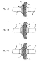
- FIGS. 1 shows an embodiment of an edging method which uses an adhesive tape 1 for edging.
- the adhesive tape 1 for edging is positioned on a convex face of the spectacle lens L.
- a lens lock tape 4 is positioned on the adhesive tape 1 for edging.
- a lens holding member (not shown) is positioned on the lens lock tape 4.
- the adhesive tape 1 for edging, the lens lock tape 4, and the lens holding member cover a machining center of the spectacle lens L.
- a chuck 2 presses against the lens lock tape 4 to the side of a chuck 3 via the lens holding member while a chuck 3 presses against the spectacle lens L to the side of the chuck 2.
- the position of the spectacle lens L is fixed relative to the chucks 2, and 3.
- Respective central positions of chucks 2 and 3 of the edge-machining apparatus correspond to a machining central portion of the spectacle lens L.
- the chucks 2 and 3 are also denoted as "lens fixing device”.
- a method of edging the spectacle lens L by using the configuration as shown in FIG. 1A is as described below. Firstly, the adhesive tape 1 for edging is attached on the convex face of the spectacle lens L such that it covers a machining central portion. Then, the lens lock tape 4 is attached on the adhesive tape 1 for edging. Thereafter, the lens holding member is attached on the lens lock tape 4. Subsequently, the lens L which is provided with the adhesive tape 1 for edging, the lens lock tape 4 and the lens holding member is inserted between the chucks 2 and 3 of the edge-machining apparatus. Then, by clamping the lens holding member, the lens lock tape 4, the adhesive tape 1 for edging, and the lens L by the chucks 2 and 3, the position of the lens L is fixed.
- the chucks 2 and 3 and the spectacle lens L are allowed to be positioned with respect to one another such that respective central positions of the chucks 2 and 3 correspond to the machining central portion of the spectacle lens L. Thereafter, a rotating grinding stone 5 is allowed to be in contact with the spectacle lens L to perform the edging of the spectacle lens L as shown in FIG. 4 .
- the adhesive tape 1 for edging is positioned on the concave face of the spectacle lens L
- the lens lock tape 4 is positioned on the convex face of the spectacle lens L.
- the chuck 2 presses against the lens lock tape 4 to the side of the chuck 3 via the lens holding member (not shown) and the chuck 3 presses against the adhesive tape 1 for edging to the side of the chuck 2 to thereby fix the position of the spectacle lens L.
- the adhesive tape 1 for edging, the lens lock tape 4 and the lens holding member cover the machining central portion of the spectacle lens L.
- the rotating grinding stone 5 is allowed to be in contact with the spectacle lens L thus held to perform edging of the spectacle lens L.
- the adhesive tape 1 for edging is positioned on each of the convex and concave faces of the spectacle lens L.
- the lens lock tape 4 is positioned on the adhesive tape 1 for edging on the convex face, and the lens holding member (not shown) is provided on the lens lock tape 4.
- the chuck 2 presses against the lens lock tape 4 to the side of the chuck 3 via the lens holding member and, at the same time, the chuck 3 presses against the adhesive tape 1 for edging of the concave side to the side of the chuck 2 to thereby fix the position of the spectacle lens L.
- two adhesive tapes 1 for edging cover the machining central portion of the spectacle lens L. Then, a rotating grinding stone 5 is allowed to be in contact with the spectacle lens 1 which is held in the manner described above to perform edging of the spectacle lens L.
- the adhesive tape 1 for edging is attached to the convex face of the spectacle lens L.
- the lens lock tape 4 is attached to the adhesive tape 1 for edging to perform the edging.
- the lens lock tape 4 is not used for the purpose of positioning, it is possible to omit the lens lock tape 4.
- another adhesive layer is formed on a face opposite to the lens face of the adhesive tape 1 for edging, since it can concurrently be used for the purpose of positioning, it is possible to omit the lens lock tape 4.
- the lens holding member of the present embodiment has biting teeth on the side which is in contact with the lens lock tape 4. Since this biting teeth bite into the lens lock tape 4, the lens L can be securely held at the time of the lens machining.
- the biting teeth of the lens holding member may be omitted or the lens holding member itself may be omitted, depending on the rotation speed of the lens L or the strength of torque to be generated by friction between the grinding stone 5 (see FIG. 4 ) and the lens L at the time of the lens machining. Further, since the structure of the lens holding member is described in detail in JP-U-6-24852 , an explanation thereon is omitted here.
- the adhesive tape 1 for edging is used, as described above, such that it is attached to only the concave face, only the convex face, or both of the concave and the convex faces of the spectacle lens which has undergone an antifouling treatment at the time of edging.
- the adhesive tape 1 is used such that it is interposed between a chuck, which holds the spectacle lens, of the edge-machining apparatus and the spectacle lens. As a result, a phenomenon in which the lens is out of position relative to the chuck, namely, an axial misalignment, can be prevented.
- the adhesive tape 1 for edging is tested by using a polyethylene terephthalate plate, in which a surface treatment has been performed with a fluorine-modified silicone parting agent, as a test plate in an adhesive test method based on the 180°-peeling method as defined in JIS Z 0237 "adhesive tape/adhesive sheet test method" ("JIS Handbook 29 Adhesion"; Japanese Standards Association, Jan. 31, 2002).
- the adhesive strength of the adhesive tape 1 for edging which is measured at that time is 4 gf (0.0392 N) or more.
- a test is performed under a standard condition in which the temperature at the test place is 23 ⁇ 2°C; and the relative humidity is 65 ⁇ 5%. A sample must be left for 2 hours or more in an atmosphere of the standard condition.
- the test piece is cut into a tape having a width of 25 mm or more or a sheet having a width of 25 mm when the tape is less than 25 mm wide, the tape is used in its original width. Three test pieces each having such width as described above and a length of about 250 mm are selected.
- a tensile testing machine as defined in JIS B 7721 is used.
- an SUS 304 or SUS 302 steel plate having a thickness of from 1.5 to 2.0 mm as defined in JIS G 4305 is selected, cut into a width of 50 mm and a length of 125 mm and, then, used.
- a hand-operated roller to be used as a pressing apparatus which is covered on its surface with a rubber layer having a spring hardness of 80 ⁇ 5 Hs and a thickness of about 6 mm as defined in JIS K 6301, has a width of about 45 mm, a diameter of about 83 mm, and a mass of 2000 ⁇ 50 g.
- Test pieces are placed on the previously cleaned test plate such that adhesive faces thereof face downward, they are aligned with one another at one end thereof with a remaining portion of 125 mm in length being set free and the adhesive face of the remaining portion is applied with talc in powder form or attached to paper.
- the roller is reciprocated one time thereon at a speed of about 300 mm/min. to press the test pieces.
- each of the test pieces is folded at an angle of 180 degrees, then, about 25 mm of the test piece is peeled off and, thereafter, the test piece is clamped by an upper chuck while the test plate is clamped by a lower chuck and, subsequently, the test piece is peeled off at a speed of 300 ⁇ 30 mm/min. Every time about 20 mm of the test piece is peeled off, the adhesive strength is read. Such reading is conducted four times. The test is conducted on 3 test pieces. An average value of the resultant 12 measurements on the 3 test pieces is determined and, then, the average value is converted to a value per 10 mm in width based on a proportional calculation.
- the test method for determining the adhesive strength of the adhesive tape for edging of the present embodiment is set in accordance with the aforementioned adhesive strength test method based on the 180°-peeling method as defined in JIS Z 0237 "adhesive tape/adhesive sheet test method".
- a polyethylene terephthalate plate having a thickness of 3 mm in which a surface treatment has been performed with a fluorine-modified silicone parting agent, is used as a test plate.
- a specific production method of the test plate for use in the test method of the present embodiment is described below.
- a fluorine-modified silicone parting agent is uniformly applied on a surface of a polyethylene terephthalate plate which is 3 mm thick, 50 mm wide and 125 mm long by, for example, a bar coat method in an amount in the range of from 0.3 g/m 2 or more to 0.6 g/m 2 or more.
- the polyethylene terephthalate plate coated with the fluorine-modified silicone parting agent is heated at about 150°C for about 60 seconds. After such heating is terminated, the side of the polyethylene terephthalate plate covered with the fluorine-modified silicone parting agent is coated with any one of ethanol, isopropyl alcohol and acetone as a cleaning liquid.
- the cleaning liquid is wiped off by, for example, gauze.
- Such coating of the cleaning liquid and wiping off are repeated at least three times until the surface of the test plate is confirmed to be clean by a visual inspection.
- a fluorine-modified silicone parting agent X-70-20 manufactured by Shin-Etsu Chemical Co. Ltd. is utilized in the present embodiment.
- the polyethylene terephthalate plate which has been coated with the fluorine-modified silicone parting agent and, then, heated is also referred to as "polyethylene terephthalate test plate" for convenience.
- An adhesive tape whose adhesive strength measured by such adhesive strength test method as described above is 4 gf (0.0392 N) or more at minimum and, preferably, 6 gf (0.0588 N) or more is strongly attached to a spectacle lens on which an antifouling layer has been formed by using the fluorine-containing silane compound as described in the aforementioned publication.
- the adhesive strength is 400 gf or less at maximum but is not limited thereto.
- the adhesive strength of the adhesive tape is unduly large, there is a risk in that a reflection reducing coating or the like which is formed on the surface of the lens is peeled off.
- the adhesive tape 1 for edging has a structure in which, in a same manner as in an ordinary adhesive tape, an adhesive layer is provided on a substrate tape.
- materials for the substrate tape materials such as the following ones are possible: polyolefin-type resins such as polyethylene, and polypropylene; polyesters such as polystyrene, and polyethylene terephthalate; thermoplastic resins such as polyvinyl acetate, ABS, a polycarbonate, a polyvinyl chloride resin, a polyamide, a polyimide, a cellulose acetate, and poly(tetrafluoroethylene); thermosetting resins such as an epoxy resin; rubber-type resins such as soft rubber, and hard rubber; and materials for reinforcing these materials, for example, a resin comprising fibrous material.
- rubber-type adhesives such as natural rubber (polyisoprene), styrene-butadiene rubber, butyl rubber, and polyisobutylene; acrylic adhesives; silicone-type adhesives; and vinyl acetate-type adhesives.
- the adhesive tape is strongly attached to the curvature of the spectacle lens and, also, endure the pressing force from the chuck.
- the substrate tape is selected based on kinetic properties such as tensile strength, and elastic modulus of traction.
- the tensile strength of the substrate tape it is preferable that the tensile strength as defined in JIS K 7127 "plastic film/sheet tensile test method" ("JIS Handbook on Steel”; Japanese Standards Association, Apr. 12, 1989) is 1 kgf/mm 2 (9.8 N/mm 2 ) or more.
- the value of the elastic modulus of traction Em as defined in the aforementioned JIS K 7127 "plastic film/sheet tensile test method” is in the range of from 1 kgf/mm 2 or more to 450 kgf/mm 2 or less (from 9.8 N/mm 2 or more to 4410 N/mm 2 or less).
- the elastic modulus of traction refers to a region that is a portion in which stress and strain are in proportion conforming to Hooke's law.
- the elastic modulus of traction of the substrate tape is unduly small, a large elongation is generated by a small load. As a result, there is a possibility of generating an axial misalignment.
- the value of the elastic modulus of traction of the substrate tape is unduly large, there is a possibility of being incapable of adapting to the lens shape.
- the thickness of the substrate tape is 10 ⁇ m or more, preferably 20 ⁇ m or more, and most preferably 30 ⁇ m or more. The maximum thereof is approximately 1 mm.
- the thickness of the adhesive layer is preferably in the range of from 1 ⁇ m or more to 100 ⁇ m or less.
- the area of the adhesive surface of the adhesive tape for edging in order to secure the necessary adhesive strength against the spectacle lens, it is preferable to ensure 700 mm 2 or more when the aforementioned adhesive strength is from 4 gf (0.0392 N) or more to less than 8 gf (0.0784 N) and 400 mm 2 or more when it is 8 gf (0.0784 N) or more.
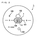
- the form of the substrate tape is not particularly limited so long as it has the aforementioned area. For example, a round, elliptical, or oblong shape is permissible. However, as shown in FIGS. 1A and 1C , when the spectacle lens is a progressive multifocal lens and the adhesive tape is attached to the convex face thereof, it is preferable that it is shaped such that it does not overlap a layout pattern which has been printed on the convex face of the progressive multifocal lens.
- layout patterns are layout markings of, for example, a horizontal reference line 101 showing the horizontal direction of the spectacle lens, a distance power measuring position 102 showing the position at which the power of a distance portion is measured, a near power measuring position 103 showing the position at which the power of a near portion is measured, a fitting point 104, and a right-or-left recognition mark 105.
- the adhesive tape 1 is attached on the fitting point 104 which shows the optical center.
- the marking of the layout pattern printed on the spectacle lens on which an antifouling layer has been formed is easily removed. For this reason, when the adhesive tape 1 for edging is attached on the layout pattern, ink of the layout pattern is attached to the adhesive tape 1 for edging. As a result, there is a risk in that the layout pattern is eliminated from the surface of the spectacle lens L. It is necessary to keep the layout pattern as it is even after the edging is performed. Therefore, in the adhesive tape 1 for edging, as shown in FIG.
- a through-hole 11 is provided in a central portion thereof such that it exposes the fitting point 104 and an outer configuration is formed to be round, elliptical or oblong such that the adhesive tape does not overlap the distance power measuring position 102 provided on the fitting point 104.
- the adhesive tape 1 for edging is attached to the concave side of the spectacle lens L, since nothing is printed on the concave side of the spectacle lens L, no restriction is put on the form thereof.
- the area of the adhesive tape 1 can be enlarged.
- the adhesive tape 1 can be attached to the entire concave face of the spectacle lens.
- the adhesive tape 1 for edging as shown in FIG. 3A comprises an adhesive layer 1 a and a substrate tape 1b.
- the substrate tape 1b has a first face and a second face which face different directions from each other.
- the adhesive layer 1a is positioned on the first face of the substrate tape 1b.
- the measurement value of the adhesive layer 1a in the adhesive tape 1 for edging is 4 gf (0.0392 N) or more in the test method of the present embodiment.
- the adhesive layer 1a provides an adhesive face for allowing the adhesive layer 1a to be in contact with the lens L.
- the lens lock tape 4 as shown in FIG. 3A comprises an adhesive layer 4a, a substrate tape 4b and an adhesive layer 4c.
- the substrate tape 4b has a first face and a second face which face different directions from each other.
- the adhesive layer 4a is positioned on the first face of the substrate tape 4b.
- the adhesive layer 4b is positioned on the second face of the substrate tape 4b. Since the adhesive portions (adhesive layers 4a and 4c) are provided on both faces (that is, first and second faces) of the substrate tape 4b, the lens lock tape 4 has a function of a so-called double-faced adhesive tape.
- a lens holding member (not shown) is attached to the adhesive layer 4c.
- the adhesive tape 1 for edging is provided such that the adhesive layer 1a and the lens L are in contact with each other.
- the lens lock tape 4 is provided such that the adhesive layer 4a and the second face of the substrate tape 1b are in contact with each other and, also, the lens holding member on the adhesive layer 4c and the chuck 2 are in contact with each other. Then, by applying pressure on the chuck 2 and the chuck 3 against each other (see FIG. 1 ), the lens L can be held between the chuck 2 and the chuck 3.
- the aforementioned lens holding member of the present embodiment has biting teeth on the side which contacts the adhesive layer 4c. Since the biting teeth bite into the adhesive layer 4c, the lens L is more securely held at the time of lens machining.
- the biting teeth of the lens holding member may be omitted or the lens holding member itself may be omitted, depending on the rotation speed of the lens L or the strength of torque to be generated by friction between the grinding stone 5 (see FIG. 4 ) and the lens L at the time of machining.
- a feature in which the biting teeth of the lens holding member or the lens holding member itself can be omitted is same as that in the configurations as shown in FIGS. 3B and 3C to be explained below. Further, as described above, since the structure of the lens holding member is described in detail in JP-U No. 6-24852 , an explanation thereon is omitted herein.
- the adhesive tape 1 for edging as shown in FIG. 3B comprises an adhesive layer 1a, a substrate tape 1b and an adhesive layer 1c.
- the substrate tape 1b has a first face and a second face which face different directions from each other.
- the adhesive layer 1a is positioned on the first face of the substrate tape 1b and, at the same time, the adhesive layer 1c is positioned on the second face of the substrate tape 1 b.
- the measurement value of the adhesive strength of the adhesive layer 1a in the adhesive tape 1 for edging is 4 gf (0.0392 N) or more in the test method of the present embodiment.
- the measurement value of the adhesive strength of the adhesive layer 1c in the adhesive tape 1 for edging is not necessarily 4 gf or more in the test method according to the present embodiment.
- the adhesive portions that is, adhesive layers 1a and 1c
- the adhesive tape 1 for edging has a function of a double-faced tape.
- the adhesive layer 1 a provides an adhesive face for being in contact with the lens L in the adhesive tape 1 for edging.
- the lens holding member (not shown) is adhered to the adhesive layer 1c.
- the adhesive layer 1 a and the lens L are in contact with each other and, at the same time, the adhesive tape 1 for edging is arranged such that the lens holding member provided on the adhesive layer 1c and the surface of the chuck 2 are in contact with each other. Then, by applying pressure to the chuck 2 and the chuck 3 against each other (see FIG. 1 ), the lens L is held between the chuck 2 and the chuck 3.
- the adhesive layer is provided not only on the first face of the substrate tape 1b but also on the second face thereof, it is not necessary to provide the lens lock tape 4 between the chuck 2 and the lens L. Namely, the tape 1 for edging simultaneously has a function of the lens lock tape 4.
- the adhesive tape 1 for edging as shown in FIG. 3C comprises an adhesive layer 1a, a first substrate tape 1b, an adhesive layer 1 c, a second substrate tape 1b', and an adhesive layer 1 d.
- the first substrate tape 1 b has a first face and a second face which face to different directions from each other.
- the adhesive layer 1 a is positioned on the first face of the first substrate tape 1b and, at the same time, the adhesive layer 1c is positioned on the second face of the first substrate tape 1b.
- the second substrate tape 1b' has a first face and a second face which face to different directions from each other.
- the first face of the second substrate tape is in contact with the adhesive layer 1c.
- the first substrate tape 1 b and the second substrate tape 1 b' are in contact with each other via the adhesive layer 1c.
- the adhesive layer 1d is positioned on the second face of the second substrate tape 1b'.
- the measurement value of the adhesive layer 1 a in the adhesive tape 1 for edging is 4 gf (0.0392 N) or more in the test method of the present embodiment.
- measurement value of the adhesive strength of the adhesive layers 1c and 1d in the adhesive tape 1 for edging are not necessarily 4 gf or more in the test method of the present embodiment.
- the adhesive layer 1a provides an adhesive face for being in contact with the lens L in the adhesive tape 1 for edging.
- the lens holding member (not shown) is adhered to the adhesive layer 1d.
- the adhesive layer 1a and the lens L are in contact with each other and, at the same time, the adhesive tape 1 for edging is arranged such that the lens holding member provided on the adhesive layer 1d and the surface of the chuck 2 are in contact with each other. Then, by applying pressure to the chuck 2 and the chuck 3 against each other (see FIG. 1 ), the lens L is fixed between the chuck 2 and the chuck 3.
- the edging method according to the present invention does not generate the axial misalignment when the spectacle lens in which the antifouling layer is provided on a surface of the spectacle lens (namely, a slippery spectacle lens) is machined. It goes without saying that an edging method does not generate the axial misalignment even when a lens which does not have an antifouling layer and, accordingly, is hardly slipped is machined.
- the material of the spectacle lens may either be inorganic glass or plastic.
- plastics mentioned are a diethylene glycol bisallylcarbonate (CR-39) resin, a polyurethane resin, a thiourethane resin, a polycarbonate resin, an acrylic resin and the like.
- Y represents hydrogen or a lower alkyl group
- R 1 represents a hydrolysable group
- q represents an integer of from 1 or more to 50 or less
- m represents an integer of from 0 or more to 2 or less
- r represents an integer of from 1 or less to 10 or more.
- a method in which the compound is dissolved in an organic solvent and, then, applied to the surface of the spectacle lens can be adopted.
- application methods mentioned are a dipping method, a spin coat method, a spray method, a flow method, a doctor blade method, a roll coat coating, a gravure coat coating, a curtain flow coating and the like.
- organic solvents mentioned are perfluorohexane, perfluoromethylcyclohexane, perfluoro-1,3-dimethylcyclohexane and the like.
- the concentration of the fluorine-containing silane compound is preferably in the range of from 0.03 wt% or more to 1 wt% or less.
- the concentration of the compound is unduly low, since it is difficult to form an antifouling layer having a sufficient thickness, a satisfactory antifouling effect can not be obtained.
- the concentration of the compound is unduly high, there is a risk in that the film thickness of the antifouling layer becomes too thick. For this reason, after the compound is applied, there is a risk of increasing the work load such that a rinse operation is conducted for eliminating a coating unevenness.
- a vacuum evaporation method in which the fluorine-containing silane compound is allowed to be evaporated in a vacuum tank and, then, deposited on the surface of the spectacle lens can also be adopted.
- a material compound can be used in a high concentration or without using a diluting solvent.
- the thickness of the antifouling layer is not particularly limited, but is from 0.001 ⁇ m or more to 0.5 ⁇ m or less and, preferably, from 0.001 ⁇ m or more to 0.03 ⁇ m or less.
- the antifouling effect becomes insufficient, whereas when the thickness thereof is unduly large, the surface becomes sticky; such feature is not favorable.
- the antifouling layer is provided on the surface of a reflection reducing coating, a thickness of the antifouling layer of 0.03 ⁇ m or more deteriorates the reflection reducing effect; such feature is also not favorable.
- the edging method according to the present embodiment is applied to a spectacle lens which has an antifouling layer comprising the fluorine-containing silane compound represented by the aforementioned general formula (1) as a main component.
- the adhesive tape for edging according to the present invention is attached to only a convex face, only a concave face, or both of these faces at the time of edging. Then, the adhesive tape is used in a state of being interposed between a chuck, which holds the spectacle lens, of the edge-machining apparatus and the spectacle lens. As a result, the axial misalignment in which the lens comes out of position relative to the chuck can be prevented.
- the present evaluation was conducted by observing presence or absence of axial misalignment generation cause by slipping between a chuck portion (position in which the lens is fixed to an axis of machining apparatus) and the surface of the lens, when the lens L is ground into a predetermined frame shape by using an edge-machining apparatus.
- a test lens is prepared and, then, set to a lens fixing jig.
- the lens having astigmatism is fixed such that the cylinder axis is set to be in a predetermined direction (for example, 180°).
- the lens having no astigmatism was ruled with a direct line which passes through the optical center of the lens.
- the lens is fixed such that the direct line is set to be in a predetermined direction (for example, 180°).
- a half-eye type frame having a large aspect ratio is prepared as a reference frame.
- an adhesive tape for edging is attached to the convex or the concave face of the lens.
- a lens lock tape is attached to the convex face of the lens.
- the resultant lens is fixed to an edge-machining apparatus ("LE-8080" manufactured by NIDEK Co., Ltd.) and, then, edge machining was performed based on previous frame data.
- the lens subjected to the edge machining is inserted into the reference frame and, then, was put to a measurement of misalignment of the cylinder axis by using a lens meter.
- a misalignment angle between such ruled line and a horizontal line which passes through an optical axis of the reference frame was measured.
- the allowable range of the axial misalignment from the predetermined direction was set to be ⁇ 2° or less.
- the adhesive tape 1 was attached to both of the convex and concave faces of the spectacle lens and the resultant spectacle lens was interposed between chucks of the edge-machining apparatus. As a result, as seen from Table 1, it was recognized that the adhesive tape 1 allows the edge machining to be performed without generating an axial misalignment even against an extremely slippery spectacle lens in which an antifouling layer was formed by performing a surface treatment by using the fluorine-containing silane compound.
- the adhesive tape 1 is attached to a spectacle lens at the time of edging and, then, used such that it is interposed between a chuck, which holds the spectacle lens, of the edge-machining apparatus and the spectacle lens.
- the present invention is not limited to the spectacle lens, but can be applied to edging of an ordinary lens.
- the present invention can be applied to an antifouling-type spectacle lens.
Landscapes
- Engineering & Computer Science (AREA)
- Chemical & Material Sciences (AREA)
- Mechanical Engineering (AREA)
- Organic Chemistry (AREA)
- Ceramic Engineering (AREA)
- Inorganic Chemistry (AREA)
- Grinding And Polishing Of Tertiary Curved Surfaces And Surfaces With Complex Shapes (AREA)
- Eyeglasses (AREA)
- Adhesive Tapes (AREA)
- Adhesives Or Adhesive Processes (AREA)
Claims (3)
- Randbearbeitungsverfahren, umfassend:a) Vorsehen eines Klebebandes mit einem Substratband und auf dem Substratband eine Klebeschicht,b) Anheften des Klebebands an eine Linse; und dannc) Randbearbeiten der Linse durch eine Randbearbeitungsmaschine während die Linse durch das Klebeband gehalten wird, das zwischen die Linse und einen Einspannbacken in der Randbearbeitungsmaschine gelegt ist, bei demdie Linse durch das Klebeband gehalten wird, wobei eine Klebefläche in Kontakt mit der Linse ist,
ein Meßwert der Haftstärke der Klebefläche 4 gf (0,0392 N) oder mehr beträgt, wenn eine Polyäthylen-Terephthalat-Platte, die einer Oberflächenbehandlung mit einem Fluormodifizierten Silikontrennmittel unterzogen wurde, als Testplatte in einem Haftstärkentestverfahren basierend auf der 180° Abziehmethode verwendet wird, wie sie in JIS Z 0237 "Klebeband/Klebeblatt-Testverfahren" definiert ist, und
der Elastizitätsmodul-Zug (Em) des Substratbands im Bereich von 1 kgf/mm2 bis 450 kgf/mm2 (10 N/mm2 bis 4,50 kN/mm2) liegt,
dadurch gekennzeichnet, daß
Schritt a) umfaßt Anheften des Klebebands an einer Antifouling-Schicht der Linse, die mit der Antifouling-Schicht ausgestattet ist, wobei die Antifouling-Schicht durch Verwenden einer Flour-haltigen Silanverbindung als Hauptbestandteil gebildet ist; und
die Linse zwischen einem Paar Einspannbacken in der Randbearbeitungsmaschine gehalten wird. - Randbearbeitungsverfahren nach Anspruch 1, dadurch gekennzeichnet, daß die Antifouling-Schicht unter Verwendung einer Fluor-haltigen Silanverbindung als Hauptbestandteil, wie sie durch die folgende allgemeine Formel wiedergegeben ist, hergestellt wird:
 wobei Rf eine geradlinige oder verzweigte Perfluoralkylgruppe mit von 1 oder mehr bis 16 oder weniger Kohlenstoffatomen darstellt;X Jod oder Wasserstoff darstellt;Y Wasserstoff oder eine niedere Alkylgruppe darstellt;Z Fluor oder eine Trifluormethylgruppe darstellt;R1 eine hydrolisierbare Gruppe darstellt;R2 Wasserstoff oder eine inaktive monovalente organische Gruppe darstellt;a, b, c und d jeweils einzeln eine ganze Zahl von 0 oder mehr bis 200 oder weniger darstellen;e 0 oder 1 darstellt;m und n jeweils einzeln eine ganze Zahl von 0 oder mehr bis 2 oder weniger darstellen; undp eine ganze Zahl von 1 oder mehr bis 10 oder weniger darstellt.
 - Randbearbeitungsverfahren gemäß einem der Ansprüche 1 oder 2, bei dem das Klebeband an einer konkaven Fläche der Linse angebracht ist.
Applications Claiming Priority (3)
| Application Number | Priority Date | Filing Date | Title |
|---|---|---|---|
| JP2003017552 | 2003-01-27 | ||
| JP2003390682A JP4185851B2 (ja) | 2003-01-27 | 2003-11-20 | 玉型加工用粘着テープの粘着力評価方法 |
| EP03775940A EP1588800B1 (de) | 2003-01-27 | 2003-11-27 | Haftklebeband und verfahren zur linsenformbearbeitung |
Related Parent Applications (1)
| Application Number | Title | Priority Date | Filing Date |
|---|---|---|---|
| EP03775940A Division EP1588800B1 (de) | 2003-01-27 | 2003-11-27 | Haftklebeband und verfahren zur linsenformbearbeitung |
Publications (2)
| Publication Number | Publication Date |
|---|---|
| EP1829645A1 EP1829645A1 (de) | 2007-09-05 |
| EP1829645B1 true EP1829645B1 (de) | 2009-01-28 |
Family
ID=32828882
Family Applications (2)
| Application Number | Title | Priority Date | Filing Date |
|---|---|---|---|
| EP07011724A Expired - Lifetime EP1829645B1 (de) | 2003-01-27 | 2003-11-27 | Schleifverfahren zum Beranden einer Linse |
| EP03775940A Expired - Lifetime EP1588800B1 (de) | 2003-01-27 | 2003-11-27 | Haftklebeband und verfahren zur linsenformbearbeitung |
Family Applications After (1)
| Application Number | Title | Priority Date | Filing Date |
|---|---|---|---|
| EP03775940A Expired - Lifetime EP1588800B1 (de) | 2003-01-27 | 2003-11-27 | Haftklebeband und verfahren zur linsenformbearbeitung |
Country Status (7)
| Country | Link |
|---|---|
| US (2) | US7278906B2 (de) |
| EP (2) | EP1829645B1 (de) |
| JP (1) | JP4185851B2 (de) |
| CN (1) | CN100560290C (de) |
| DE (2) | DE60320461T2 (de) |
| SG (1) | SG153665A1 (de) |
| WO (1) | WO2004067227A1 (de) |
Families Citing this family (24)
| Publication number | Priority date | Publication date | Assignee | Title |
|---|---|---|---|---|
| US6942746B2 (en) * | 2003-12-11 | 2005-09-13 | Optima, Inc. | Lens blocking system |
| EP1803531B1 (de) | 2004-10-15 | 2014-07-23 | Musashi Chemicals Industry Co., Ltd. | Ein Haftklebeband verwendende Verfahren zur Bearbeitung einer Linse |
| WO2006082635A1 (ja) * | 2005-02-02 | 2006-08-10 | Vigteqnos Co., Ltd. | フッ素コートメガネレンズ研削用軸ズレ防止パッド |
| JP2006299115A (ja) * | 2005-04-21 | 2006-11-02 | Sun A Kaken Co Ltd | 滑り防止用粘着フィルム |
| ATE523291T1 (de) * | 2006-02-17 | 2011-09-15 | Essilor Int | Verfahren zur ätzung optischer linsen |
| WO2007132694A1 (ja) | 2006-05-12 | 2007-11-22 | Seiko Epson Corporation | 粘着シートおよび玉型加工方法 |
| JP4598749B2 (ja) | 2006-12-21 | 2010-12-15 | セイコーエプソン株式会社 | 粘着テープ及び粘着テープの貼り付け方法 |
| EP1987917A1 (de) * | 2007-05-03 | 2008-11-05 | Saint-Gobain Performance Plastics Corporation | Ophthalmisches Blockierpad |
| US7935402B2 (en) * | 2007-05-03 | 2011-05-03 | Saint-Gobain Performance Plastics Corporation | Ophthalmic blocking pad |
| EP2145730A1 (de) * | 2008-07-17 | 2010-01-20 | Essilor International (Compagnie Générale D'Optique) | Verfahren und entsprechende Vorrichtung zum Halten und Lösen von Linsen |
| FR2938255B1 (fr) | 2008-11-13 | 2011-04-01 | Essilor Int | Procede de traitement au moyen d'un film adhesif d'une lentille optique comportant un revetement antisalissure en vue de son debordage |
| JP2010158727A (ja) * | 2009-01-06 | 2010-07-22 | Hoya Corp | レンズ加工用パッド、その製造方法、プラスチックレンズの製造方法および粘着部材 |
| US8297441B2 (en) * | 2009-08-04 | 2012-10-30 | Pepsico, Inc. | Protective contact strips for beverage trays |
| KR102210773B1 (ko) * | 2012-12-11 | 2021-02-02 | 에씰로 앙터나시오날 | 광학 렌즈 부재를 테이핑하는 방법 |
| US20150118944A1 (en) * | 2013-01-31 | 2015-04-30 | Ebara Corporation | Polishing apparatus, method for attaching polishing pad, and method for replacing polishing pad |
| JP6275248B2 (ja) * | 2013-09-18 | 2018-02-07 | ティッセンクルップ スチール ヨーロッパ アクチェンゲゼルシャフトThyssenKrupp Steel Europe AG | 被覆された平坦な製品の摩耗特性を判定する方法および装置 |
| JP6061830B2 (ja) * | 2013-09-27 | 2017-01-18 | オリンパス株式会社 | レンズ加工装置及びレンズ加工方法 |
| CN106457705B (zh) | 2014-05-20 | 2019-04-05 | 依视路国际公司 | 涂覆有图案化的可去除的膜的光学镜片及用于对此类镜片磨边的方法 |
| CN104044035A (zh) * | 2014-05-30 | 2014-09-17 | 丹阳市鑫烨光学仪器有限公司 | 镜片磨边优化工艺 |
| JP6286644B2 (ja) * | 2014-05-30 | 2018-03-07 | 東海光学株式会社 | ずれ防止用コート剤 |
| JP6543464B2 (ja) * | 2014-12-26 | 2019-07-10 | ホヤ レンズ タイランド リミテッドHOYA Lens Thailand Ltd | 眼鏡レンズ |
| CN104977254B (zh) * | 2015-07-20 | 2019-02-22 | 深圳市华星光电技术有限公司 | 比较复合膜片的粘着力及选定合格品的方法 |
| CN107932198B (zh) * | 2017-12-08 | 2019-02-15 | 苏州大学 | 一种消边缘效应的非球面镜加工方法 |
| KR20210145888A (ko) * | 2020-05-25 | 2021-12-03 | 삼성디스플레이 주식회사 | 접착력 측정 방법 |
Family Cites Families (25)
| Publication number | Priority date | Publication date | Assignee | Title |
|---|---|---|---|---|
| FR1577425A (de) * | 1968-04-25 | 1969-08-08 | ||
| JP2656371B2 (ja) | 1990-06-26 | 1997-09-24 | 富士通株式会社 | 光ディスク装置 |
| US5210695A (en) * | 1990-10-26 | 1993-05-11 | Gerber Optical, Inc. | Single block mounting system for surfacing and edging of a lens blank and method therefor |
| JP3041654B2 (ja) | 1991-09-19 | 2000-05-15 | 王子製紙株式会社 | 再剥離性粘着シート |
| US5165202A (en) * | 1991-10-18 | 1992-11-24 | Spindel Jr Gilbert D | Methods and apparatus for making spectacle frame lens patterns |
| JP2604753Y2 (ja) * | 1992-08-31 | 2000-06-05 | ホーヤ株式会社 | 眼鏡レンズ保持装置 |
| SE9202925D0 (sv) * | 1992-10-07 | 1992-10-07 | Kabi Pharmacia Ab | Method in the production of intraocular lenses |
| DE4300673C2 (de) | 1993-01-13 | 1994-10-13 | Wernicke & Co Gmbh | Positionierhilfe für einen Block oder Sauger zum Halten eines Brillenglases |
| CA2159797A1 (en) * | 1994-10-28 | 1996-04-29 | John H. Ko | Compliant lens block and tape |
| US5883169A (en) * | 1995-01-26 | 1999-03-16 | Sola International Holdings Ltd. | Lens wafers with removable coating |
| JPH09258003A (ja) * | 1996-03-22 | 1997-10-03 | Sumitomo Chem Co Ltd | 防汚性レンズ |
| US5928718A (en) * | 1997-09-25 | 1999-07-27 | Dillon; Stephen M. | Protective coating for reflective sunglasses |
| JP2000024936A (ja) * | 1998-07-10 | 2000-01-25 | Kimoto & Co Ltd | 研磨フィルム |
| JP2000309759A (ja) | 1999-04-27 | 2000-11-07 | Sekisui Chem Co Ltd | 粘着テープ |
| JP2001011396A (ja) | 1999-06-28 | 2001-01-16 | Toagosei Co Ltd | シートの施工方法 |
| JP2001064608A (ja) | 1999-09-01 | 2001-03-13 | Nitto Denko Corp | 無機薄膜積層体及び無機薄膜形成体 |
| JP3275147B1 (ja) | 2000-02-22 | 2002-04-15 | ホーヤ株式会社 | レンズホルダへの弾性シール貼着方法 |
| JP2002263998A (ja) * | 2001-01-05 | 2002-09-17 | Seiko Epson Corp | ポリシャ及び研磨方法 |
| DE60232497D1 (de) * | 2001-01-05 | 2009-07-16 | Seiko Epson Corp | Poliervorrichtung und -verfahren |
| DE10114238A1 (de) | 2001-03-22 | 2002-10-02 | Loh Optikmaschinen Ag | Anordnung zum Blocken und Spannen von am Rand zu bearbeitenden optischen Linsen, insbesondere Brillengläsern |
| JP3715939B2 (ja) | 2001-09-27 | 2005-11-16 | 積水化学工業株式会社 | 粘着テープ |
| JP4046546B2 (ja) | 2002-04-30 | 2008-02-13 | 日東電工株式会社 | メガネ用レンズの研磨方法および該研磨方法で用いられる粘着シート |
| JP3715601B2 (ja) | 2002-08-05 | 2005-11-09 | ソーラオプティカルジャパン株式会社 | 眼鏡用レンズの玉型加工に用いる軸ずれ防止キット及びこれを用いた眼鏡用レンズの玉型加工方法 |
| JP2004347660A (ja) | 2003-05-20 | 2004-12-09 | Nikon-Essilor Co Ltd | 撥油コート付き眼鏡レンズの玉摺加工方法、撥油コート付き眼鏡レンズの製造方法及び粘着剤付テープ |
| CN100590460C (zh) * | 2005-03-11 | 2010-02-17 | 精工爱普生株式会社 | 塑料透镜以及制造塑料透镜的方法 |
-
2003
- 2003-11-20 JP JP2003390682A patent/JP4185851B2/ja not_active Expired - Fee Related
- 2003-11-27 SG SG200701778-3A patent/SG153665A1/en unknown
- 2003-11-27 EP EP07011724A patent/EP1829645B1/de not_active Expired - Lifetime
- 2003-11-27 CN CNB2003801001590A patent/CN100560290C/zh not_active Expired - Fee Related
- 2003-11-27 EP EP03775940A patent/EP1588800B1/de not_active Expired - Lifetime
- 2003-11-27 DE DE60320461T patent/DE60320461T2/de not_active Expired - Lifetime
- 2003-11-27 DE DE60326062T patent/DE60326062D1/de not_active Expired - Lifetime
- 2003-11-27 WO PCT/JP2003/015192 patent/WO2004067227A1/ja not_active Ceased
-
2004
- 2004-07-27 US US10/899,047 patent/US7278906B2/en not_active Expired - Fee Related
-
2007
- 2007-09-21 US US11/859,675 patent/US20080026216A1/en not_active Abandoned
Also Published As
| Publication number | Publication date |
|---|---|
| JP4185851B2 (ja) | 2008-11-26 |
| DE60320461T2 (de) | 2009-05-20 |
| EP1588800A4 (de) | 2006-05-24 |
| WO2004067227A1 (ja) | 2004-08-12 |
| CN100560290C (zh) | 2009-11-18 |
| DE60320461D1 (de) | 2008-05-29 |
| EP1588800A1 (de) | 2005-10-26 |
| US7278906B2 (en) | 2007-10-09 |
| SG153665A1 (en) | 2009-07-29 |
| JP2004249454A (ja) | 2004-09-09 |
| HK1079150A1 (zh) | 2006-03-31 |
| DE60326062D1 (de) | 2009-03-19 |
| US20080026216A1 (en) | 2008-01-31 |
| CN1684796A (zh) | 2005-10-19 |
| EP1588800B1 (de) | 2008-04-16 |
| US20050042977A1 (en) | 2005-02-24 |
| EP1829645A1 (de) | 2007-09-05 |
Similar Documents
| Publication | Publication Date | Title |
|---|---|---|
| EP1829645B1 (de) | Schleifverfahren zum Beranden einer Linse | |
| EP2025461A1 (de) | Haftklebefolie und säumverfahren | |
| US11061171B2 (en) | Method for improving the edging of an optical article by providing a temporary layer of an organic matter | |
| CN102216407B (zh) | 处理光学透镜用于修边的方法 | |
| JP6257897B2 (ja) | 光学物品およびその製造方法 | |
| US20050126687A1 (en) | Lens blocking system | |
| JP5524060B2 (ja) | 二層仮皮膜を有する光学物品 | |
| KR101525861B1 (ko) | 지방족 열가소성 폴리우레탄의 임시 층을 포함하는 광학 물품 및 에징에서의 사용 | |
| US20080117382A1 (en) | Electrostatic Film Coated Ophthalmic Lens And Method For Edging Same | |
| CA2751626C (en) | Surface modification of hydrophobic and/or oleophobic coatings | |
| JP4544249B2 (ja) | レンズ保持構造及び玉型加工方法 | |
| JP2013228437A (ja) | 眼鏡レンズ、眼鏡レンズの製造方法および処理液 | |
| HK1079150B (en) | Edging method | |
| BRPI0707918A2 (pt) | processo para acabamento de borda de uma lente óptica, e, lente óptica |
Legal Events
| Date | Code | Title | Description |
|---|---|---|---|
| PUAI | Public reference made under article 153(3) epc to a published international application that has entered the european phase |
Free format text: ORIGINAL CODE: 0009012 |
|
| AC | Divisional application: reference to earlier application |
Ref document number: 1588800 Country of ref document: EP Kind code of ref document: P |
|
| AK | Designated contracting states |
Kind code of ref document: A1 Designated state(s): DE FR GB |
|
| 17P | Request for examination filed |
Effective date: 20080103 |
|
| 17Q | First examination report despatched |
Effective date: 20080211 |
|
| AKX | Designation fees paid |
Designated state(s): DE FR GB |
|
| GRAP | Despatch of communication of intention to grant a patent |
Free format text: ORIGINAL CODE: EPIDOSNIGR1 |
|
| GRAS | Grant fee paid |
Free format text: ORIGINAL CODE: EPIDOSNIGR3 |
|
| GRAA | (expected) grant |
Free format text: ORIGINAL CODE: 0009210 |
|
| AC | Divisional application: reference to earlier application |
Ref document number: 1588800 Country of ref document: EP Kind code of ref document: P |
|
| AK | Designated contracting states |
Kind code of ref document: B1 Designated state(s): DE FR GB |
|
| REG | Reference to a national code |
Ref country code: GB Ref legal event code: FG4D |
|
| REF | Corresponds to: |
Ref document number: 60326062 Country of ref document: DE Date of ref document: 20090319 Kind code of ref document: P |
|
| PLBE | No opposition filed within time limit |
Free format text: ORIGINAL CODE: 0009261 |
|
| STAA | Information on the status of an ep patent application or granted ep patent |
Free format text: STATUS: NO OPPOSITION FILED WITHIN TIME LIMIT |
|
| 26N | No opposition filed |
Effective date: 20091029 |
|
| REG | Reference to a national code |
Ref country code: DE Ref legal event code: R082 Ref document number: 60326062 Country of ref document: DE Representative=s name: MERH-IP MATIAS ERNY REICHL HOFFMANN, DE |
|
| REG | Reference to a national code |
Ref country code: DE Ref legal event code: R082 Ref document number: 60326062 Country of ref document: DE Representative=s name: MERH-IP MATIAS ERNY REICHL HOFFMANN PATENTANWA, DE Effective date: 20130611 Ref country code: DE Ref legal event code: R082 Ref document number: 60326062 Country of ref document: DE Representative=s name: MERH-IP MATIAS ERNY REICHL HOFFMANN, DE Effective date: 20130611 Ref country code: DE Ref legal event code: R081 Ref document number: 60326062 Country of ref document: DE Owner name: HOYA LENS MANUFACTURING PHILIPPINES INC., PH Free format text: FORMER OWNER: SEIKO EPSON CORP., TOKYO, JP Effective date: 20130611 |
|
| REG | Reference to a national code |
Ref country code: FR Ref legal event code: TP Owner name: HOYA LENS MANUFACTURING PHILIPPINES INC., PH Effective date: 20131003 |
|
| REG | Reference to a national code |
Ref country code: GB Ref legal event code: 732E Free format text: REGISTERED BETWEEN 20140220 AND 20140226 |
|
| REG | Reference to a national code |
Ref country code: FR Ref legal event code: PLFP Year of fee payment: 13 |
|
| REG | Reference to a national code |
Ref country code: FR Ref legal event code: PLFP Year of fee payment: 14 |
|
| REG | Reference to a national code |
Ref country code: FR Ref legal event code: PLFP Year of fee payment: 15 |
|
| PGFP | Annual fee paid to national office [announced via postgrant information from national office to epo] |
Ref country code: DE Payment date: 20171121 Year of fee payment: 15 Ref country code: FR Payment date: 20171012 Year of fee payment: 15 |
|
| PGFP | Annual fee paid to national office [announced via postgrant information from national office to epo] |
Ref country code: GB Payment date: 20171122 Year of fee payment: 15 |
|
| REG | Reference to a national code |
Ref country code: DE Ref legal event code: R119 Ref document number: 60326062 Country of ref document: DE |
|
| GBPC | Gb: european patent ceased through non-payment of renewal fee |
Effective date: 20181127 |
|
| PG25 | Lapsed in a contracting state [announced via postgrant information from national office to epo] |
Ref country code: DE Free format text: LAPSE BECAUSE OF NON-PAYMENT OF DUE FEES Effective date: 20190601 Ref country code: FR Free format text: LAPSE BECAUSE OF NON-PAYMENT OF DUE FEES Effective date: 20181130 |
|
| PG25 | Lapsed in a contracting state [announced via postgrant information from national office to epo] |
Ref country code: GB Free format text: LAPSE BECAUSE OF NON-PAYMENT OF DUE FEES Effective date: 20181127 |