EP1826454A2 - Schwingungsdämpfer mit amplitudenselektiver Dämpfkraft - Google Patents
Schwingungsdämpfer mit amplitudenselektiver Dämpfkraft Download PDFInfo
- Publication number
- EP1826454A2 EP1826454A2 EP07002878A EP07002878A EP1826454A2 EP 1826454 A2 EP1826454 A2 EP 1826454A2 EP 07002878 A EP07002878 A EP 07002878A EP 07002878 A EP07002878 A EP 07002878A EP 1826454 A2 EP1826454 A2 EP 1826454A2
- Authority
- EP
- European Patent Office
- Prior art keywords
- vibration damper
- housing
- damper according
- working chamber
- opening
- Prior art date
- Legal status (The legal status is an assumption and is not a legal conclusion. Google has not performed a legal analysis and makes no representation as to the accuracy of the status listed.)
- Granted
Links
- 238000013016 damping Methods 0.000 title claims abstract description 27
- 230000001419 dependent effect Effects 0.000 claims description 4
- 230000000694 effects Effects 0.000 description 5
- 238000005192 partition Methods 0.000 description 3
- 230000003247 decreasing effect Effects 0.000 description 2
- 238000003780 insertion Methods 0.000 description 2
- 230000037431 insertion Effects 0.000 description 2
- 230000007704 transition Effects 0.000 description 2
- 238000000418 atomic force spectrum Methods 0.000 description 1
- 238000010276 construction Methods 0.000 description 1
- 230000007423 decrease Effects 0.000 description 1
- 230000004048 modification Effects 0.000 description 1
- 238000012986 modification Methods 0.000 description 1
- 238000005096 rolling process Methods 0.000 description 1
Images



Classifications
-
- F—MECHANICAL ENGINEERING; LIGHTING; HEATING; WEAPONS; BLASTING
- F16—ENGINEERING ELEMENTS AND UNITS; GENERAL MEASURES FOR PRODUCING AND MAINTAINING EFFECTIVE FUNCTIONING OF MACHINES OR INSTALLATIONS; THERMAL INSULATION IN GENERAL
- F16F—SPRINGS; SHOCK-ABSORBERS; MEANS FOR DAMPING VIBRATION
- F16F9/00—Springs, vibration-dampers, shock-absorbers, or similarly-constructed movement-dampers using a fluid or the equivalent as damping medium
- F16F9/32—Details
- F16F9/50—Special means providing automatic damping adjustment, i.e. self-adjustment of damping by particular sliding movements of a valve element, other than flexions or displacement of valve discs; Special means providing self-adjustment of spring characteristics
- F16F9/512—Means responsive to load action, i.e. static load on the damper or dynamic fluid pressure changes in the damper, e.g. due to changes in velocity
- F16F9/5126—Piston, or piston-like valve elements
-
- F—MECHANICAL ENGINEERING; LIGHTING; HEATING; WEAPONS; BLASTING
- F16—ENGINEERING ELEMENTS AND UNITS; GENERAL MEASURES FOR PRODUCING AND MAINTAINING EFFECTIVE FUNCTIONING OF MACHINES OR INSTALLATIONS; THERMAL INSULATION IN GENERAL
- F16F—SPRINGS; SHOCK-ABSORBERS; MEANS FOR DAMPING VIBRATION
- F16F2230/00—Purpose; Design features
- F16F2230/42—Multiple pistons
Definitions
- the invention relates to a vibration damper with amplitude-selective damping force according to the preamble of patent claim 1.
- a vibration damper with amplitude-selective damping force in which a disc-shaped separating element within a housing performs an axial movement.
- the displaced by the piston rod damping medium volume is received via a bypass passage to a damping valve from a working chamber in the housing.
- the separator occupies an end stop position at one end of the housing.
- An elastic stop is arranged on the separating element, which on the one hand should avoid impact noise and effect a softer damping force transition to the damping valve.
- a separating element which has in the direction of a piston rod pin on a thorn-like extension, which in dips an axial passage to the piston rod remote working space and this increasingly closes.
- the object of the present invention is to provide an alternative solution to the problem of noise and the soft Dämpfkraftübergangs.
- connection cross-section is formed by at least one radial opening in the working chamber and the separating element forms a slide valve with the radial opening.
- the separating element changes during an axial movement the effective cross section and thus a throttling effect of the radial opening.
- the throttling action prevents a noisy striking of the separating element in its end position. Furthermore, a smooth transition to the use of the damping valve is achieved.
- a plurality of radial openings are executed at an axial distance. With increasing stroke of the separating element, the radial openings can be run over.
- the working chamber is connected in the filling direction with an opening non-return valve. It should be avoided that a negative pressure builds up in a working chamber of the housing, which affects the amplitude-selective effect of the vibration damper.
- the check valve is connected to a separate inlet port for connection opening.
- a tube insert may be arranged in the housing, which forms at least a part of a working chamber and with the inner wall of the housing for at least one of the working chamber a separate inlet channel.
- a circumferential web is executed between the inner wall of the housing and the tube insert, which separates the two inlet channels from each other.
- the circumferential web can be carried by the housing or the tube insert.
- the tube insert braces axially at least one end of the housing a valve body of the check valve.
- valve body consists of two layered, valve body discs and between the two valve body discs a Vorö Stammss is clamped with the outflow from a working chamber of the housing defining Vorö Maschinensquerites.
- the tube insert is designed with at least one connection opening, which is variable in its effective cross section.
- the minimum amplitude-dependent damping force of a desired characteristic can be adjusted without using additional or other components.
- a ring element is arranged adjustable with a setting opening for use of the tube.
- the ring element is braced radially with the tube insert and can rest on the inside or outside.
- a ring member may also serve a ring segment which extends over a circumferential angle of more than 180 °.
- the tube insert and the housing define at least one channel, wherein the at least connection opening can be brought into coincidence relative to the housing by a rotational movement of the tube insert.
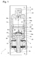
- FIG. 1 shows a detail of a vibration damper 1 in the region of a piston 5 fastened to a piston rod 3.
- the vibration damper comprises a cylinder 7 filled with damping medium, which cylinder flows from the piston 5 into two working chambers 9; 11 is divided.
- the piston rod 3 carries, in this case in the piston rod-side working space 9, a housing 17 in which a disk-shaped separating element 19 two working chambers 21, 23 from each other.
- the housing 17 is designed in two parts and consists of two pot-like elements 17a; 17b, which are pushed into one another on a longitudinal section 17c and form an annular space 25 in the region of the overlap.
- the lower working chamber 23 in the direction of the piston 5 is connected via an axial channel 27 in the piston rod pin 5z with the piston rod remote working space 11.
- the axial channel 27 opens into the housing 17 and communicates with the annular space 25 in connection.
- a plurality of radial openings 33 a - 33 c are designed at an axial distance, which determine a connection cross-section to the annular space 25.
- the upper working chamber 21 also has a plurality of radial openings 35a-35c with axial spacing. Alternatively, a single radial opening 35 with decreasing width in the direction of End of the respective working chamber 21; 23 are used, as shown in dashed lines.
- the check valve body 31 has a spring-loaded check valve disk 37; which lifts in the filling direction of the working chamber 23 and at least one passage 39 releases.
- the upper working chamber 21 also has a check valve 41, z. B. in the design of a ball valve, which is connected to a separate to the radial openings 35 a - 35 c inlet channel 43. Starting from an operating position of the separating element 19 at the upper end of the housing 17, the damping medium can flow out of the cylinder in the direction of arrow A via the inlet channel 43 and the open check valve 41 in the upper working chamber 21 of the housing 17 during a Ausschub Gay of the piston 5.
- the explodedriförmige separator 19 forms with the radial openings 35a - 35c a slide valve, which is still closed.
- damping medium flows into the upper working chamber 21 and moves the disc-shaped separating element 19 in the direction of the check valve 31.
- the displaced from the lower working chamber 23 damping medium can via the open radial openings 33a - 33c in the annular space 25 and then further through the axial channel 27th drain into the piston rod remote working space 11. In doing so, only a comparatively small damping force is generated, if at all.
- the radial openings 33a-33c in the lower working chamber 23 with the outer surface 19m partition member 19 perform a slide valve function.
- the separating element 19 gradually closes the radial openings 33a - 33c, so that the effective connection cross section in Direction of the annular space 25 decreases and increasingly sets a damping force.
- the check valve 37 is closed in this direction of movement of the separating element 19.
- the radial openings 33a - 33c are closed to the extent that a hydraulic short circuit can not occur in the presence of the end position of the separating element 19.
- the check valve 37 opens and it builds up a pressure force in the lower working chamber 23, which shifts the separating element 19 in the direction of the upper end of the housing 17.
- the check valve 41 on the inlet channel is closed.
- the partition element 1 is initially displaced in the housing with no or only a slight damping effect even with an insertion movement until the radial openings 35a - 35c are gradually closed by the disk-shaped separating element 19.
- the housing 17 has at least one connection opening 53, which is connected to the inlet channel 47.
- valve body 31 Between the ends of the housing 17 and the tube insert 45 are valve body 31: 35 for check valves 37; 41 axially braced.
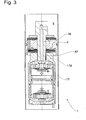
- FIG. 3 shows a modification of FIG. 2.
- the essential difference is that the housing 17 is arranged below the piston 5 in the working chamber 11 remote from the piston rod.
- An upper lid 17d is provided with a fixing thread 57 fixing the piston 5 on the piston rod pin 5z.
- Fig. 4 shows a variant of Figure 2, in which a Vorö Maschinensquerites 59; 61, the outflow from the working chambers 21; 23 and thus determines the damping force in the phase of the amplitude-dependent damping.
- the two valve body 31; 55 each divided into two and stratified executed.
- Between the two valve body disks 31 a; 31b; 55a; 55b is at least one pre-opening disk 57; 59 strained.
- the valve body disks 31 a; 31b and 55a, respectively; 55b are together with the associated check valves 37; 41 riveted and can therefore very easily be checked prior to assembly, inter alia, on the throttling effect of Vorö Samuelsiden and thus adapted to a desired damping force curve.
- a further possibility for setting a Vorö Samuelsqueritess to be displayed Based on the principle of Fig. 2 are in the tube insert 45 per working chamber at least one connection opening 33; 35 executed. Radially on the outside is per working chamber 21; 23 at least one ring element 62; 63 in an annular groove 65; 67 strained.
- the ring element has a circumferential angle of more than 180 ° and is rotatable in the annular groove in the circumferential direction.
- In the ring member is at least one adjustment opening 69; 71 carried out, in registration with the respective connection opening 33; 35 determines the effective Vorö Stammsquerrough.
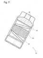
- FIGS. 6 and 7 describe in a combination a variant in which the effective pre-opening cross-section is infinitely adjustable.
- a housing 17 which, on its inner wall, starts from the annular spaces 47; 49, of the valve bodies 31; 55 are limited to the housing 17, in each case at least one helical groove 73; 75, which extends as far as the circumferential ridge 51.
- the tubular body 45 is applied over a large area to the inner wall of the housing, so that the tube insert 45 with its outer wall and the housing with its inner wall by grooves 73; 75 define a channel, wherein the connection openings 33a - 33c; 35a - 35c can be brought by a twisting movement of the tube insert relative to the housing in a desired coverage, wherein the overlap is the effective Vorö Stammsquerites.
Landscapes
- Engineering & Computer Science (AREA)
- General Engineering & Computer Science (AREA)
- Physics & Mathematics (AREA)
- Fluid Mechanics (AREA)
- Mechanical Engineering (AREA)
- Fluid-Damping Devices (AREA)
- Buildings Adapted To Withstand Abnormal External Influences (AREA)
Abstract
Description
- Die Erfindung betrifft einen Schwingungsdämpfer mit amplitudenselektiver Dämpfkraft gemäß dem Oberbegriff von Patentanspruch 1.
- Aus der gattungsbildenden
EP 1 496 285 A2 ist ein Schwingungsdämpfer mit amplitudenselektiver Dämpfkraft bekannt, bei dem ein scheibenförmiges Trennelement innerhalb eines Gehäuses eine Axialbewegung ausführt. Das durch die Kolbenstange verdrängte Dämpfmediumvolumen wird über einen Bypasskanal zu einem Dämpfventil von einer Arbeitskammer in dem Gehäuse aufgenommen. Wenn das verdrängte Dämpfmediumvolumen die Arbeitskammer maximal gefüllt hat, nimmt das Trennelement eine Endanschlagposition an einem Ende des Gehäuses ein. An dem Trennelement ist ein elastischer Anschlag angeordnet, der einerseits Anschlaggeräusche vermeiden und einen weicheren Dämpfkraftübergang zum Dämpfventil bewirken soll. - In der Ausführung nach Fig. 4 kommt ein Trennelement zur Anwendung, das in Richtung eines Kolbenstangenzapfens über einen dornartigen Fortsatz verfügt, der in einen Axialkanal zum kolbenstangenfernen Arbeitsraum eintaucht und diesen zunehmend verschließt.
- Aufgabe der vorliegenden Erfindung ist es, eine Alternativlösung für das Problem der Geräuschbildung und des weichen Dämpfkraftübergangs zu schaffen.
- Erfindungsgemäß wird die Aufgabe dadurch gelöst, dass der Anschlussquerschnitt von mindestens einer radialen Öffnung in der Arbeitskammer gebildet wird und das Trennelement mit der radialen Öffnung ein Schieberventil bildet.
- Das Trennelement verändert bei einer Axialbewegung den wirksamen Querschnitt und damit eine Drosselwirkung der radialen Öffnung. Die Drosselwirkung verhindert ein geräuschvolles Anschlagen des Trennelements in seine Endlagenstellung. Des Weiteren wird ein weicher Übergang zum Einsatz des Dämpfventils erreicht.
- Gemäß einem vorteilhaften Unteranspruch sind mehrere radiale Öffnungen in axialem Abstand ausgeführt. Mit zunehmendem Hubweg des Trennelements können die radialen Öffnungen überfahren werden.
- Des Weiteren ist vorgesehen, dass die Arbeitskammer in Füllrichtung mit einem sich öffnenden Rückschlagventil verbunden ist. Es soll vermieden werden, dass sich in einer Arbeitskammer des Gehäuses ein Unterdruck aufbaut, der die amplitudenselektive Wirkung des Schwingungsdämpfers beeinträchtigt.
- Bei einer vorteilhaften Ausgestaltung ist das Rückschlagventil an einem zur Anschlussöffnung separaten Einlasskanal angeschlossen.
- Alternativ kann in dem Gehäuse ein Rohreinsatz angeordnet sein, der zumindest einen Teil einer Arbeitskammer und mit der Innenwandung des Gehäuses für mindestens eine der Arbeitskammer einen separaten Einlasskanal bildet.
- ln weiterer vorteilhafter Ausgestaltung ist zwischen der Innenwandung des Gehäuses und dem Rohreinsatz ein umlaufender Steg ausgeführt, der die beiden Einlasskanäle voneinander trennt. Der umlaufende Steg kann von dem Gehäuse oder dem Rohreinsatz getragen werden.
- Der Rohreinsatz verspannt axial zumindest mit einem Ende des Gehäuses einen Ventilkörper des Rückschlagventils.
- Des Weiteren kann vorgesehen sein, dass der Ventilkörper aus zwei geschichteten, Ventilkörperscheiben besteht und zwischen den beiden Ventilkörperscheiben eine Voröffnungsscheibe mit einem den Abfluss aus einer Arbeitskammer des Gehäuses bestimmenden Voröffnungsquerschnitt verspannt ist. Durch eine gezielte Auswahl der Voröffnungsscheibe kann die Dämpfkraftkennlinie im Bereich der amplitudenabhängigen Dämpfung gezielt angepasst werden.
- Gemäß einem vorteilhaften Unteranspruch ist der Rohreinsatz mit mindestens einer Anschlussöffnung ausgeführt, die in ihrem wirksamen Querschnitt veränderbar ist.
- Dadurch kann die minimale amplitudenabhängige Dämpfkraft einer gewünschten Kennlinie angepasst werden, ohne zusätzliche oder andere Bauteile zu verwenden.
- Dabei ist ein Ringelement mit einer Einstellöffnung zum Rohreinsatz verstellbar angeordnet.
- Das Ringelement ist radial mit dem Rohreinsatz verspannt und kann dabei innen- oder außenseitig anliegen. Als Ringelement kann auch ein Ringsegment dienen, das sich über einen Umfangswinkel von mehr als 180° erstreckt.
- Bei einer alternativen Lösung begrenzen der Rohreinsatz und das Gehäuse mindestens einen Kanal, wobei die mindestens Anschlussöffnung durch eine Verdrehbewegung des Rohreinsatzes relativ zum Gehäuse in Überdeckung gebracht werden kann.
- Anhand der folgenden Figurenbeschreibung soll die Erfindung näher erläutert werden.
- Es zeigt:
- Fig. 1
- Amplitudenselektiver Schwingungsdämpfer mit einem separaten Einlasskanal für eine Arbeitskammer
- Fig. 2
- Schwingungsdämpfer mit einem Rohreinsatz im Gehäuse für die amplitudenselektive Dämpfkraft
- Fig. 3
- Alternative zur Fig. 2 mit Gehäuse im kolbenstangenfernen Arbeitsraum
- Fig.4
- Einstellbarer Voröffnungsquerschnitt in einem scheibenförmig geteilten Ventilkörper
- Fig. 5
- Einstellbarer Voröffnungsquerschnitt durch verdrehbares Ringelement
- Fig. 6 u. 7
- Einstellbarer Voröffnungsquerschnitt durch Verdrehung eines Rohreinsatzes relativ zu einem Gehäuse
- Die Figur 1 zeigt einen Ausschnitt von einem Schwingungsdämpfer 1 im Bereich eines an einer Kolbenstange 3 befestigten Kolbens 5. Der Schwingungsdämpfer umfasst einen mit Dämpfmedium gefüllten Zylinder 7, der von dem Kolben 5 in zwei Arbeitsräume 9; 11 unterteilt wird. In dem Kolben 5 sind mit Ventilscheiben bestückte Dämpfventile 13; 15 für die Ein- und Ausschubrichtung der Kolbenstange ausgeführt. Die Kolbenstange 3 trägt, in diesem Fall im kolbenstangenseitigen Arbeitsraum 9, ein Gehäuse 17, in dem ein scheibenförmiges Trennelement 19 zwei Arbeitskammern 21, 23 voneinander trennt. Das Gehäuse 17 ist zweigeteilt ausgeführt und besteht aus zwei topfartigen Elementen 17a; 17b, die auf einem Längenabschnitt 17c ineinander geschoben sind und im Bereich der Überlappung einen Ringraum 25 bilden. Die untere Arbeitskammer 23 in Richtung des Kolbens 5 ist über einen Axialkanal 27 im Kolbenstangenzapfen 5z mit dem kolbenstangenfernen Arbeitsraum 11 verbünden. Zwischen einem Boden 29 des Gehäuses 17 und einem Rückschlagventilkörper 31 mündet der Axialkanal 27 im Gehäuse 17 und steht mit dem Ringraum 25 in Verbindung. In dem Längenabschnitt17c des oberen topfartigen Elements 17a sind in axialem Abstand mehrere radiale Öffnungen 33a -33c ausgeführt, die einen Anschlussquerschnitt zum Ringraum 25 bestimmen. Auch die obere Arbeitkammer 21 verfügt über mehrere radiale Öffnungen 35a - 35c mit axialem Abstand. Alternativ kann auch eine einzige radiale Öffnung 35 mit abnehmender Breite in Richtung des Endes der jeweiligen Arbeitskammer 21; 23 verwendet werden, wie gestrichelt dargestellt ist.
- Der Rückschlagventilkörper 31 verfügt über eine federkraftbelastete Rückschlagventilscheibe 37; die in Füllrichtung der Arbeitskammer 23 abhebt und mindestens einen Durchlass 39 freigibt. Die obere Arbeitskammer 21 verfügt ebenfalls über ein Rückschlagventil 41, z. B. in der Bauform eines Kugelventils, das an einem zu den radialen Öffnungen 35a - 35c separaten Einlasskanal 43 angeschlossen ist.
Ausgehend von einer Betriebsstellung des Trennelements 19 am oberen Ende des Gehäuses 17 kann das Dämpfmedium bei einer Ausschubbewegung des Kolbens 5 aus dem Zylinder in Pfeilrichtung A über den Einlasskanal 43 und das geöffnete Rückschlagventil 41 in die obere Arbeitskammer 21 des Gehäuses 17 einströmen. Das scheiberiförmige Trennelement 19 bildet mit der radialen Öffnungen 35a - 35c ein Schieberventil, das dabei noch geschlossen ist. Mit zunehmender Hubbewegung strömt Dämpfmedium in die obere Arbeitskammer 21 und verschiebt das scheibenförmige Trennelement 19 in Richtung des Rückschlagventils 31. Das aus der unteren Arbeitskammer 23 verdrängte Dämpfmedium kann über die geöffneten radialen Öffnungen 33a - 33c in den Ringraum 25 und dann weiter durch den Axialkanal 27 in den kolbenstangenfernen Arbeitsraum 11 abfließen. Dabei wird, wenn überhaupt, nur eine vergleichsweise kleine Dämpfkraft erzeugt. Wenn das scheibenförmige Trennelement 19 weiter in Richtung des unteren Endes des Gehäuses verschoben wird, üben die radialen Öffnungen 33a - 33c in der unteren Arbeitskammer 23 mit der Mantelfläche 19m Trennelement 19 eine Schieberventilfunktion aus. Das Trennelement 19 verschließt nach und nach die radialen Öffnungen 33a - 33c, so dass der wirksame Anschlussquerschnitt in Richtung des Ringraums 25 abnimmt und sich zunehmend eine Dämpfkraft einstellt. Das Rückschlagventil 37 ist bei dieser Bewegungsrichtung des Trennelements 19 geschlossen. Wenn die untere Endstellung des Trennelements erreicht ist, hat sich das Dämpfventil 15 oder wird dann vom Druck im kolbenstangenfernen Arbeitsraum 9 geöffnet. - Bei einer Einschubbewegung des Kolbens 5 in Richtung des kolbenstangenfernen Arbeitsraums 11 sind bei Vorliegen der Endlage des Trennelements 19 die radialen Öffnungen 33a - 33c soweit verschlossen, dass ein hydraulischer Kurschluss nicht auftreten kann. Das Rückschlagventil 37 öffnet und es baut sich in der unteren Arbeitskammer 23 eine Druckkraft auf, die das Trennelement 19 in Richtung des oberen Endes des Gehäuses 17 verschiebt. Das Rückschlagventil 41 am Einlasskanal ist geschlossen. Genauso wie bei einer Ausschubbewegung des Kolbens 5 wird auch bei einer Einschubbewegung der Trennelement 1 im Gehäuse anfangs ohne oder nur mit einer geringen Dämpfwirkung verschoben, bis die radialen Öffnungen 35a - 35c nach und nach von dem scheibenförmigen Trennelement 19 verschlossen werden. Bei einer einzigen radialen Öffnung 35 wird der wirksame Anschlussquerschnitt entsprechend verkleinert. Durch eine Verdrehung der Gehäuseteile 17a; 17b verändern sich die Überlappungen der Öffnungen 33a - 33cmit den Axialkanälen 25, wodurch sich der wirksame Abflussquerschnitt stufenlos einstellen lässt.
- Die Variante nach Fig. 2 funktioniert exakt wie die Lösung nach Fig. 1. Abweichend kommt im Gehäuse 17 ein Rohreinsatz 45 zur Anwendung, der mit der Innenwandung des Gehäuses 17 jeweils einen separaten Einlasskanal 47; 49 für eine Arbeitskammer 21; 23 bildet. Ein umlaufender Steg 51 mit einer Dichtung 52 zwischen der Innenwandung des Gehäuses 17 und dem Rohreinsatz 45 trennt die beiden Einlasskanäle 47; 49 voneinander. Im Gehäuse 17 ist mindestens eine Anschlussöffnung 53 ausgeführt, die mit dem Einlasskanal 47 verbunden ist. In dem Rohreinsatz sind wie in Fig. 1 pro Arbeitskammer mehrere radiale Öffnungen 33a - 33c; 35a - 35c oder alternativ mindestens eine radiale Öffnungen 33; 35 mit abnehmendem Anschlussquerschnitt ausgeführt, die in den Einlasskanälen 47; 49 münden. Zwischen den Enden des Gehäuses 17 und dem Rohreinsatz 45 sind Ventilkörper 31: 35 für Rückschlagventile 37; 41 axial verspannt.
- Die Figur 3 zeigt eine Abwandlung zur Fig. 2. Der wesentliche Unterschied besteht darin, dass das Gehäuse 17 im kolbenstangenfernen Arbeitsraum 11 unterhalb des Kolbens 5 angeordnet ist. Ein oberer Deckel 17d ist mit einem Befestigungsgewinde 57 versehen, das den Kolben 5 auf dem Kolbenstangenzapfen 5z fixiert.
- Die Fig. 4 zeigt eine Variante zur Fig. 2, bei der ein Voröffnungsquerschnitt 59; 61, der das Ausströmen aus den Arbeitskammern 21; 23 und damit die Dämpfkraft in der Phase der amplitudenabhängigen Dämpfung bestimmt. Dazu sind die beiden Ventilkörper 31; 55 jeweils zweigeteilt und geschichtet ausgeführt. Zwischen den beiden Ventilkörperscheiben 31 a; 31b; 55a; 55b ist mindestens eine Voröffnungsscheibe 57; 59 verspannt. Die Ventilkörperscheiben 31 a; 31 b bzw. 55a; 55b sind zusammen mit den zugehörigen Rückschlagventilen 37; 41 vernietet und können deshalb sehr einfach vor der Montage u. a. auch auf die Drosselwirkung der Voröffnungsscheiben überprüft und damit einer gewünschten Dämpfkraftkennlinie angepasst werden.
- Mit der Fig. 5 soll eine weitere Möglichkeit zur Einstellung eines Voröffnungsquerschnitts dargestellt werden. Aufbauend auf dem Prinzip nach Fig. 2 sind in dem Rohreinsatz 45 pro Arbeitskammer mindestens eine Anschlussöffnung 33; 35 ausgeführt. Radial außenseitig ist pro Arbeitskammer 21; 23 mindestens ein Ringelement 62; 63 in einer Ringnut 65; 67 verspannt. Das Ringelement verfügt über einen Umfangswinkel von mehr als 180° und ist in der Ringnut in Umfangsrichtung verdrehbar. In dem Ringelement ist mindestens eine Einstellöffnung 69; 71 ausgeführt, die in Überdeckung mit der jeweiligen Anschlussöffnung 33; 35 den wirksamen Voröffnungsquerschnitt bestimmt.
- Die Figuren 6 und 7 beschreiben in der Zusammenschau eine Variante, bei der der wirksame Voröffnungsquerschnitt stufenlos einstellbar ist. Ausgehend von der Grundkonstruktion nach Fig. 3 kommt ein Gehäuse 17 zur Anwendung, das an seiner Innenwandung ausgehend von den Ringräumen 47; 49, die von den Ventilkörpern 31; 55 mit dem Gehäuse 17 begrenzt werden, jeweils mindestens eine wendelförmige Nut 73; 75 aufweisen, die sich maximal bis zum umlaufenden Steg 51 erstreckt. Der Rohrkörper 45 liegt großflächig an der Innenwandung des Gehäuses an, so dass der Rohreinsatz 45 mit seiner Außenwandung und das Gehäuse mit seiner Innenwandung durch Nuten 73; 75 einen Kanal begrenzen, wobei die Anschlussöffnungen 33a - 33c; 35a - 35c durch eine Verdrehbewegung des Rohreinsatzes relativ zum Gehäuse in einer gewünschte Überdeckung gebracht werden kann, wobei die Überdeckung den wirksamen Voröffnungsquerschnitt darstellt.
- Die Einstellung des wirksamen Voröffnungsquerschnitts kann ganz einfach vor dem Verrollen des Gehäuserandes 77 mit dem Boden 29 vorgenommen werden.
Claims (12)
- Schwingungsdämpfer (1) mit amplitudenselektiver Dämpfkraft, umfassend eine in einem mit Dämpfmedium gefüllten Zylinder (7) axial bewegliche Kolbenstange (3) mit einem Kolben (5), der den Zylinder (7) in zwei Arbeitsräume (9; 11) unterteilt, wobei die Kolbenstange (3) ein Gehäuse (17) trägt, in dem ein scheibenförmigen Trennelement (19) zwei Arbeitskammer (21; 23) trennt, wobei beide Arbeitskammer (21; 23) jeweils über einen Anschlussquerschnitt mit einem der Arbeitsräume (9; 11) verbunden sind und der Anschlussquerschnitt für mindestens eine Bewegungsrichtung der Kolbenstange von Trennelement (19) hubabhängig verändert wird,
dadurch gekennzeichnet,
dass der Anschlussquerschnitt von mindestens einer radialen Öffnung (33; 33a - 33c; 35; 35a - 35c) in der Arbeitskammer (21; 23) gebildet wird und das Trennelement (19) mit der radialen Öffnung (33; 33a - 33c; 35; 35a - 35c) ein Schieberventil bildet. - Schwingungsdämpfer nach Anspruch 1,
dadurch gekennzeichnet,
dass mehrere radiale Öffnungen (33a - 33c; 35a - 35c)in axialem Abstand ausgeführt sind. - Schwingungsdämpfer nach Anspruch 1,
dadurch gekennzeichnet,
dass die Arbeitskammer (21; 23) in Füllrichtung mit einem sich öffnenden Rückschlagventil (37; 41) verbunden ist. - Schwingungsdämpfer nach Anspruch 3,
dadurch gekennzeichnet,
dass das Rückschlagventil (41) an einem zur Anschlussöffnung (33a - 33c) separaten Einlasskanal angeschlossen ist. - Schwingungsdämpfer nach Anspruch 3,
dadurch gekennzeichnet,
dass in dem Gehäuse (17) ein Rohreinsatz (45) angeordnet ist der zumindest einen Teil einer Arbeitskammer (21; 23) und mit der Innenwandung des Gehäuses (17) für mindestens eine Arbeitskammer (21; 23) einen separaten Einlasskanal (47: 49) bildet. - Schwingungsdämpfer nach Anspruch 5,
dadurch gekennzeichnet,
dass zwischen der Innenwandung des Gehäuses (17) und dem Rohreinsatz (45) ein umlaufender Steg (51) ausgeführt ist, der die beiden Einlasskanäle (47; 49) voneinander trennt. - Schwingungsdämpfer nach Anspruch 5,
dadurch gekennzeichnet,
dass der Rohreinsatz (45) zumindest mit einem Ende des Gehäuses (17) einen Ventilkörper (31; 55) des Rückschlagventils (37; 41) axial verspannt. - Schwingungsdämpfer nach Anspruch 7,
dadurch gekennzeichnet,
dass der Ventilkörper (31; 55) zwei geschichteten Ventilkörperscheiben (31a 31b; 55a; 55b) umfasst und zwischen den beiden Ventilkörperscheiben (31a; 31b; 55a; 55b) eine Voröffnungsscheibe (58; 59) mit einem den Abfluss aus einer Arbeitskammer (21; 23) des Gehäuses (17) bestimmenden Voröffnungsquerschnitt (59; 61) verspannt ist. - Schwingungsdämpfer nach Anspruch 5,
dadurch gekennzeichnet,
dass der Rohreinsatz (45) mit mindestens einer Anschlussöffnung (33a; 33b; 33c 35a; 35b; 35c) ausgeführt ist, die in ihrem wirksamen Querschnitt veränderbar ist - Schwingungsdämpfer nach Anspruch 9,
dadurch gekennzeichnet,
dass ein Ringelement (62; 63) mit einer Einstellöffnung (71; 73) zum Rohreinsatz (45) verstellbar angeordnet ist. - Schwingungsdämpfer nach Anspruch 10,
dadurch gekennzeichnet,
dass das Ringelement (62; 63) radial mit dem Rohreinsatz (45) verspannt ist. - Schwingungsdämpfer nach Anspruch 5,
dadurch gekennzeichnet,
dass der Rohreinsatz (45) und das Gehäuse (17) mindestens einen Kanal (73 75) begrenzen, wobei die die mindestens Anschlussöffnung (33a - 33c; 35a - 35c) durch eine Verdrehbewegung des Rohreinsatzes (45) relativ zum Gehäuse (17) in Überdeckung gebracht werden kann.
Applications Claiming Priority (1)
| Application Number | Priority Date | Filing Date | Title |
|---|---|---|---|
| DE102006008675A DE102006008675B3 (de) | 2006-02-24 | 2006-02-24 | Schwingungsdämpfer mit amplitudenselektiver Dämpfkraft |
Publications (3)
| Publication Number | Publication Date |
|---|---|
| EP1826454A2 true EP1826454A2 (de) | 2007-08-29 |
| EP1826454A3 EP1826454A3 (de) | 2008-08-27 |
| EP1826454B1 EP1826454B1 (de) | 2010-04-28 |
Family
ID=38042828
Family Applications (1)
| Application Number | Title | Priority Date | Filing Date |
|---|---|---|---|
| EP07002878A Not-in-force EP1826454B1 (de) | 2006-02-24 | 2007-02-10 | Schwingungsdämpfer mit amplitudenselektiver Dämpfkraft |
Country Status (3)
| Country | Link |
|---|---|
| EP (1) | EP1826454B1 (de) |
| AT (1) | ATE466210T1 (de) |
| DE (2) | DE102006008675B3 (de) |
Cited By (7)
| Publication number | Priority date | Publication date | Assignee | Title |
|---|---|---|---|---|
| EP1908984A3 (de) * | 2006-10-05 | 2010-04-28 | ZF Friedrichshafen AG | Schwingungsdämpfer mit amplitudenselektiver Dämpfkraft |
| US20130056317A1 (en) * | 2011-09-02 | 2013-03-07 | Tae Ju Kim | Frequency/pressure sensitive shock absorber |
| US20140238798A1 (en) * | 2011-10-04 | 2014-08-28 | Koni B.V. | Fluid-filled, frequency-dependent damper |
| WO2014191226A1 (de) * | 2013-05-27 | 2014-12-04 | Thyssenkrupp Bilstein Gmbh | Schwingungsdämpfer für ein fahrzeug |
| CN104541084A (zh) * | 2012-08-06 | 2015-04-22 | 萱场工业株式会社 | 缓冲装置 |
| EP3048327A4 (de) * | 2013-09-19 | 2017-07-12 | KYB Corporation | Dämpfungsvorrichtung |
| CN111664217A (zh) * | 2020-07-03 | 2020-09-15 | 山推工程机械股份有限公司 | 一种热模锻压机减振及能量回收控制方法 |
Families Citing this family (8)
| Publication number | Priority date | Publication date | Assignee | Title |
|---|---|---|---|---|
| KR100894799B1 (ko) * | 2007-12-05 | 2009-04-22 | 주식회사 만도 | 쇽업소버 |
| DE102008001106B3 (de) * | 2008-04-10 | 2009-06-18 | Zf Friedrichshafen Ag | Schwingungsdämpfer mit amplitudenabhängiger Dämpfkraft |
| DE102009001567B3 (de) * | 2009-03-16 | 2010-06-24 | Zf Friedrichshafen Ag | Schwingungsdämpfer mit amplitudenabhängiger Dämpfkraft |
| KR101288612B1 (ko) * | 2011-07-21 | 2013-07-22 | 주식회사 만도 | 쇽업소버의 밸브 구조 |
| DE102013008888A1 (de) * | 2013-05-27 | 2014-08-28 | Thyssenkrupp Bilstein Gmbh | Schwingungsdämpfer für ein Fahrzeug |
| DE102013008887B4 (de) * | 2013-05-27 | 2016-01-28 | Thyssenkrupp Bilstein Gmbh | Schwingungsdämpfer für ein Fahrzeug |
| DE102013111502B4 (de) | 2013-10-18 | 2018-09-27 | Thyssenkrupp Bilstein Gmbh | Schwingungsdämpfer mit amplitudenabhängiger Dämpfung |
| DE102016201862A1 (de) | 2016-02-08 | 2017-08-10 | Zf Friedrichshafen Ag | Schwingungsdämpfer mit einem Ausgleichsraum |
Citations (3)
| Publication number | Priority date | Publication date | Assignee | Title |
|---|---|---|---|---|
| GB2250080A (en) | 1990-10-19 | 1992-05-27 | Tokico Ltd | Hydraulic shock absorber |
| US5386892A (en) | 1992-09-18 | 1995-02-07 | Tokico, Ltd. | Hydraulic shock absorber with shutters |
| EP1496285A2 (de) | 2003-07-08 | 2005-01-12 | ThyssenKrupp Bilstein GmbH | Schwingungsdämpfer mit amplitudenabhängiger Dämpfung |
Family Cites Families (4)
| Publication number | Priority date | Publication date | Assignee | Title |
|---|---|---|---|---|
| FR2070461A5 (de) * | 1969-12-05 | 1971-09-10 | Martin Claude | |
| DE4238728A1 (de) * | 1992-11-17 | 1994-05-19 | Stabilus Gmbh | Schwingungsdämpfer mit geschwindigkeitsabhängiger Veränderung der Dämpfungskraft |
| DE10360140A1 (de) * | 2003-12-20 | 2005-07-21 | Daimlerchrysler Ag | Dämpfungsvorrichtung für ein Kraftfahrzeug |
| DE102004043925A1 (de) * | 2004-09-11 | 2006-03-30 | Daimlerchrysler Ag | Dämpfungsvorrichtung |
-
2006
- 2006-02-24 DE DE102006008675A patent/DE102006008675B3/de not_active Expired - Fee Related
-
2007
- 2007-02-10 AT AT07002878T patent/ATE466210T1/de active
- 2007-02-10 DE DE502007003557T patent/DE502007003557D1/de active Active
- 2007-02-10 EP EP07002878A patent/EP1826454B1/de not_active Not-in-force
Patent Citations (3)
| Publication number | Priority date | Publication date | Assignee | Title |
|---|---|---|---|---|
| GB2250080A (en) | 1990-10-19 | 1992-05-27 | Tokico Ltd | Hydraulic shock absorber |
| US5386892A (en) | 1992-09-18 | 1995-02-07 | Tokico, Ltd. | Hydraulic shock absorber with shutters |
| EP1496285A2 (de) | 2003-07-08 | 2005-01-12 | ThyssenKrupp Bilstein GmbH | Schwingungsdämpfer mit amplitudenabhängiger Dämpfung |
Cited By (10)
| Publication number | Priority date | Publication date | Assignee | Title |
|---|---|---|---|---|
| EP1908984A3 (de) * | 2006-10-05 | 2010-04-28 | ZF Friedrichshafen AG | Schwingungsdämpfer mit amplitudenselektiver Dämpfkraft |
| US20130056317A1 (en) * | 2011-09-02 | 2013-03-07 | Tae Ju Kim | Frequency/pressure sensitive shock absorber |
| US8978845B2 (en) * | 2011-09-02 | 2015-03-17 | Mando Corporation | Frequency/pressure sensitive shock absorber |
| US20140238798A1 (en) * | 2011-10-04 | 2014-08-28 | Koni B.V. | Fluid-filled, frequency-dependent damper |
| US9856940B2 (en) * | 2011-10-04 | 2018-01-02 | Koni B.V. | Fluid-filled, frequency-dependent damper |
| CN104541084A (zh) * | 2012-08-06 | 2015-04-22 | 萱场工业株式会社 | 缓冲装置 |
| EP2881614A4 (de) * | 2012-08-06 | 2016-09-14 | Kyb Corp | Stossdämpfer |
| WO2014191226A1 (de) * | 2013-05-27 | 2014-12-04 | Thyssenkrupp Bilstein Gmbh | Schwingungsdämpfer für ein fahrzeug |
| EP3048327A4 (de) * | 2013-09-19 | 2017-07-12 | KYB Corporation | Dämpfungsvorrichtung |
| CN111664217A (zh) * | 2020-07-03 | 2020-09-15 | 山推工程机械股份有限公司 | 一种热模锻压机减振及能量回收控制方法 |
Also Published As
| Publication number | Publication date |
|---|---|
| DE502007003557D1 (de) | 2010-06-10 |
| EP1826454A3 (de) | 2008-08-27 |
| DE102006008675B3 (de) | 2007-09-13 |
| ATE466210T1 (de) | 2010-05-15 |
| EP1826454B1 (de) | 2010-04-28 |
Similar Documents
| Publication | Publication Date | Title |
|---|---|---|
| EP1826454B1 (de) | Schwingungsdämpfer mit amplitudenselektiver Dämpfkraft | |
| EP1745222B1 (de) | Luftfeder | |
| DE102010002937B3 (de) | Schwingungsdämpfer mit hubabhängiger Dämpfkraft | |
| EP1775495A2 (de) | Schwingungsdämpfer mit verstellbarer Dämpfkraft | |
| DE1505478A1 (de) | Stufenlos verstellbarer Stossdaempfer,insbesondere fuer Kraftfahrzeuge | |
| DE102014210705A1 (de) | Frequenzabhängige Dämpfventilanordnung | |
| WO2018054603A1 (de) | Dämpfventil für einen schwingungsdämpfer | |
| DE102008001106B3 (de) | Schwingungsdämpfer mit amplitudenabhängiger Dämpfkraft | |
| DE10058136C1 (de) | Umschaltventil mit strömungsrichtungsabhängigem Querschnitt | |
| EP1104514A1 (de) | Hydraulischer schwingungsdämpfer für kraftfahrzeuge | |
| WO2017198403A1 (de) | Schwingungsdämpfer mit hubabhängiger dämpfkraft | |
| WO2018103982A1 (de) | Hydraulischer endanschlag für einen schwingungsdämpfer | |
| DE19542293A1 (de) | Schwingungsdämpfer mit einstellbarer Dämpfkraft | |
| DE10343875B4 (de) | Schwingungsdämpfer mit hubabhängiger Dämpfkraft | |
| DE1281865B (de) | Stufenlos verstellbarer Stossdaempfer, insbesondere fuer Kraftfahrzeuge | |
| EP1767811B1 (de) | Schwingungsdämpfer mit amplitudenselektiver Dämpfkraft | |
| EP2103836A2 (de) | Schwingungsdämpfer mit amplitudenselektiver Dämpfkraft | |
| DE102004034057B4 (de) | Schwingungsdämpfer mit amplitudenabhängiger Dämpfkraft | |
| DE10047878B4 (de) | Stossdämpfer mit amplitudenabhängiger Dämpfung | |
| DE4445705A1 (de) | Schwingungsdämpfer mit verstellbarer Dämpfkraft | |
| DE102008042637B4 (de) | Ventileinrichtung mit amplitudenabhängiger Dämpfkraft | |
| WO2018054601A1 (de) | Dämpfventil für einen schwingungsdämpfer | |
| DE102010031037B4 (de) | Schwingungsdämpfer mit frequenzselektiver Dämpfkraft | |
| EP2191165B1 (de) | Schwingungsdämpfer mit amplitudenabhängiger dämpfkraft | |
| EP2128482B1 (de) | Schwingungsdämpfer mit amplitudenabhängiger Dämpfkraft |
Legal Events
| Date | Code | Title | Description |
|---|---|---|---|
| PUAI | Public reference made under article 153(3) epc to a published international application that has entered the european phase |
Free format text: ORIGINAL CODE: 0009012 |
|
| AK | Designated contracting states |
Kind code of ref document: A2 Designated state(s): AT BE BG CH CY CZ DE DK EE ES FI FR GB GR HU IE IS IT LI LT LU LV MC NL PL PT RO SE SI SK TR |
|
| AX | Request for extension of the european patent |
Extension state: AL BA HR MK YU |
|
| PUAL | Search report despatched |
Free format text: ORIGINAL CODE: 0009013 |
|
| AK | Designated contracting states |
Kind code of ref document: A3 Designated state(s): AT BE BG CH CY CZ DE DK EE ES FI FR GB GR HU IE IS IT LI LT LU LV MC NL PL PT RO SE SI SK TR |
|
| AX | Request for extension of the european patent |
Extension state: AL BA HR MK RS |
|
| 17P | Request for examination filed |
Effective date: 20080820 |
|
| 17Q | First examination report despatched |
Effective date: 20081001 |
|
| AKX | Designation fees paid |
Designated state(s): AT BE BG CH CY CZ DE DK EE ES FI FR GB GR HU IE IS IT LI LT LU LV MC NL PL PT RO SE SI SK TR |
|
| GRAP | Despatch of communication of intention to grant a patent |
Free format text: ORIGINAL CODE: EPIDOSNIGR1 |
|
| GRAS | Grant fee paid |
Free format text: ORIGINAL CODE: EPIDOSNIGR3 |
|
| GRAA | (expected) grant |
Free format text: ORIGINAL CODE: 0009210 |
|
| AK | Designated contracting states |
Kind code of ref document: B1 Designated state(s): AT BE BG CH CY CZ DE DK EE ES FI FR GB GR HU IE IS IT LI LT LU LV MC NL PL PT RO SE SI SK TR |
|
| REG | Reference to a national code |
Ref country code: GB Ref legal event code: FG4D Free format text: NOT ENGLISH |
|
| REG | Reference to a national code |
Ref country code: CH Ref legal event code: EP |
|
| REG | Reference to a national code |
Ref country code: IE Ref legal event code: FG4D Free format text: LANGUAGE OF EP DOCUMENT: GERMAN |
|
| REF | Corresponds to: |
Ref document number: 502007003557 Country of ref document: DE Date of ref document: 20100610 Kind code of ref document: P |
|
| REG | Reference to a national code |
Ref country code: NL Ref legal event code: VDEP Effective date: 20100428 |
|
| LTIE | Lt: invalidation of european patent or patent extension |
Effective date: 20100428 |
|
| PG25 | Lapsed in a contracting state [announced via postgrant information from national office to epo] |
Ref country code: LT Free format text: LAPSE BECAUSE OF FAILURE TO SUBMIT A TRANSLATION OF THE DESCRIPTION OR TO PAY THE FEE WITHIN THE PRESCRIBED TIME-LIMIT Effective date: 20100428 Ref country code: SE Free format text: LAPSE BECAUSE OF FAILURE TO SUBMIT A TRANSLATION OF THE DESCRIPTION OR TO PAY THE FEE WITHIN THE PRESCRIBED TIME-LIMIT Effective date: 20100428 Ref country code: NL Free format text: LAPSE BECAUSE OF FAILURE TO SUBMIT A TRANSLATION OF THE DESCRIPTION OR TO PAY THE FEE WITHIN THE PRESCRIBED TIME-LIMIT Effective date: 20100428 Ref country code: ES Free format text: LAPSE BECAUSE OF FAILURE TO SUBMIT A TRANSLATION OF THE DESCRIPTION OR TO PAY THE FEE WITHIN THE PRESCRIBED TIME-LIMIT Effective date: 20100808 |
|
| REG | Reference to a national code |
Ref country code: IE Ref legal event code: FD4D |
|
| PG25 | Lapsed in a contracting state [announced via postgrant information from national office to epo] |
Ref country code: FI Free format text: LAPSE BECAUSE OF FAILURE TO SUBMIT A TRANSLATION OF THE DESCRIPTION OR TO PAY THE FEE WITHIN THE PRESCRIBED TIME-LIMIT Effective date: 20100428 Ref country code: IS Free format text: LAPSE BECAUSE OF FAILURE TO SUBMIT A TRANSLATION OF THE DESCRIPTION OR TO PAY THE FEE WITHIN THE PRESCRIBED TIME-LIMIT Effective date: 20100828 Ref country code: LV Free format text: LAPSE BECAUSE OF FAILURE TO SUBMIT A TRANSLATION OF THE DESCRIPTION OR TO PAY THE FEE WITHIN THE PRESCRIBED TIME-LIMIT Effective date: 20100428 Ref country code: SI Free format text: LAPSE BECAUSE OF FAILURE TO SUBMIT A TRANSLATION OF THE DESCRIPTION OR TO PAY THE FEE WITHIN THE PRESCRIBED TIME-LIMIT Effective date: 20100428 |
|
| PG25 | Lapsed in a contracting state [announced via postgrant information from national office to epo] |
Ref country code: PL Free format text: LAPSE BECAUSE OF FAILURE TO SUBMIT A TRANSLATION OF THE DESCRIPTION OR TO PAY THE FEE WITHIN THE PRESCRIBED TIME-LIMIT Effective date: 20100428 Ref country code: CY Free format text: LAPSE BECAUSE OF FAILURE TO SUBMIT A TRANSLATION OF THE DESCRIPTION OR TO PAY THE FEE WITHIN THE PRESCRIBED TIME-LIMIT Effective date: 20100512 |
|
| PG25 | Lapsed in a contracting state [announced via postgrant information from national office to epo] |
Ref country code: GR Free format text: LAPSE BECAUSE OF FAILURE TO SUBMIT A TRANSLATION OF THE DESCRIPTION OR TO PAY THE FEE WITHIN THE PRESCRIBED TIME-LIMIT Effective date: 20100729 Ref country code: EE Free format text: LAPSE BECAUSE OF FAILURE TO SUBMIT A TRANSLATION OF THE DESCRIPTION OR TO PAY THE FEE WITHIN THE PRESCRIBED TIME-LIMIT Effective date: 20100428 Ref country code: DK Free format text: LAPSE BECAUSE OF FAILURE TO SUBMIT A TRANSLATION OF THE DESCRIPTION OR TO PAY THE FEE WITHIN THE PRESCRIBED TIME-LIMIT Effective date: 20100428 Ref country code: PT Free format text: LAPSE BECAUSE OF FAILURE TO SUBMIT A TRANSLATION OF THE DESCRIPTION OR TO PAY THE FEE WITHIN THE PRESCRIBED TIME-LIMIT Effective date: 20100830 Ref country code: IE Free format text: LAPSE BECAUSE OF FAILURE TO SUBMIT A TRANSLATION OF THE DESCRIPTION OR TO PAY THE FEE WITHIN THE PRESCRIBED TIME-LIMIT Effective date: 20100428 |
|
| PG25 | Lapsed in a contracting state [announced via postgrant information from national office to epo] |
Ref country code: CZ Free format text: LAPSE BECAUSE OF FAILURE TO SUBMIT A TRANSLATION OF THE DESCRIPTION OR TO PAY THE FEE WITHIN THE PRESCRIBED TIME-LIMIT Effective date: 20100428 Ref country code: SK Free format text: LAPSE BECAUSE OF FAILURE TO SUBMIT A TRANSLATION OF THE DESCRIPTION OR TO PAY THE FEE WITHIN THE PRESCRIBED TIME-LIMIT Effective date: 20100428 Ref country code: RO Free format text: LAPSE BECAUSE OF FAILURE TO SUBMIT A TRANSLATION OF THE DESCRIPTION OR TO PAY THE FEE WITHIN THE PRESCRIBED TIME-LIMIT Effective date: 20100428 |
|
| PLBE | No opposition filed within time limit |
Free format text: ORIGINAL CODE: 0009261 |
|
| STAA | Information on the status of an ep patent application or granted ep patent |
Free format text: STATUS: NO OPPOSITION FILED WITHIN TIME LIMIT |
|
| PG25 | Lapsed in a contracting state [announced via postgrant information from national office to epo] |
Ref country code: IT Free format text: LAPSE BECAUSE OF FAILURE TO SUBMIT A TRANSLATION OF THE DESCRIPTION OR TO PAY THE FEE WITHIN THE PRESCRIBED TIME-LIMIT Effective date: 20100428 |
|
| 26N | No opposition filed |
Effective date: 20110131 |
|
| BERE | Be: lapsed |
Owner name: ZF FRIEDRICHSHAFEN A.G. Effective date: 20110228 |
|
| PG25 | Lapsed in a contracting state [announced via postgrant information from national office to epo] |
Ref country code: MC Free format text: LAPSE BECAUSE OF NON-PAYMENT OF DUE FEES Effective date: 20110228 |
|
| REG | Reference to a national code |
Ref country code: CH Ref legal event code: PL |
|
| GBPC | Gb: european patent ceased through non-payment of renewal fee |
Effective date: 20110210 |
|
| PG25 | Lapsed in a contracting state [announced via postgrant information from national office to epo] |
Ref country code: CH Free format text: LAPSE BECAUSE OF NON-PAYMENT OF DUE FEES Effective date: 20110228 Ref country code: LI Free format text: LAPSE BECAUSE OF NON-PAYMENT OF DUE FEES Effective date: 20110228 |
|
| PG25 | Lapsed in a contracting state [announced via postgrant information from national office to epo] |
Ref country code: BE Free format text: LAPSE BECAUSE OF NON-PAYMENT OF DUE FEES Effective date: 20110228 |
|
| PG25 | Lapsed in a contracting state [announced via postgrant information from national office to epo] |
Ref country code: GB Free format text: LAPSE BECAUSE OF NON-PAYMENT OF DUE FEES Effective date: 20110210 |
|
| REG | Reference to a national code |
Ref country code: AT Ref legal event code: MM01 Ref document number: 466210 Country of ref document: AT Kind code of ref document: T Effective date: 20120210 |
|
| PGFP | Annual fee paid to national office [announced via postgrant information from national office to epo] |
Ref country code: FR Payment date: 20130301 Year of fee payment: 7 |
|
| PG25 | Lapsed in a contracting state [announced via postgrant information from national office to epo] |
Ref country code: LU Free format text: LAPSE BECAUSE OF NON-PAYMENT OF DUE FEES Effective date: 20110210 |
|
| PG25 | Lapsed in a contracting state [announced via postgrant information from national office to epo] |
Ref country code: AT Free format text: LAPSE BECAUSE OF NON-PAYMENT OF DUE FEES Effective date: 20120210 |
|
| PG25 | Lapsed in a contracting state [announced via postgrant information from national office to epo] |
Ref country code: TR Free format text: LAPSE BECAUSE OF FAILURE TO SUBMIT A TRANSLATION OF THE DESCRIPTION OR TO PAY THE FEE WITHIN THE PRESCRIBED TIME-LIMIT Effective date: 20100428 Ref country code: BG Free format text: LAPSE BECAUSE OF FAILURE TO SUBMIT A TRANSLATION OF THE DESCRIPTION OR TO PAY THE FEE WITHIN THE PRESCRIBED TIME-LIMIT Effective date: 20100728 |
|
| PG25 | Lapsed in a contracting state [announced via postgrant information from national office to epo] |
Ref country code: HU Free format text: LAPSE BECAUSE OF FAILURE TO SUBMIT A TRANSLATION OF THE DESCRIPTION OR TO PAY THE FEE WITHIN THE PRESCRIBED TIME-LIMIT Effective date: 20100428 |
|
| REG | Reference to a national code |
Ref country code: FR Ref legal event code: ST Effective date: 20141031 |
|
| PG25 | Lapsed in a contracting state [announced via postgrant information from national office to epo] |
Ref country code: FR Free format text: LAPSE BECAUSE OF NON-PAYMENT OF DUE FEES Effective date: 20140228 |
|
| PGFP | Annual fee paid to national office [announced via postgrant information from national office to epo] |
Ref country code: DE Payment date: 20150203 Year of fee payment: 9 |
|
| REG | Reference to a national code |
Ref country code: DE Ref legal event code: R119 Ref document number: 502007003557 Country of ref document: DE |
|
| PG25 | Lapsed in a contracting state [announced via postgrant information from national office to epo] |
Ref country code: DE Free format text: LAPSE BECAUSE OF NON-PAYMENT OF DUE FEES Effective date: 20160901 |