EP1826431A2 - Schaltvorrichtung mit Synchronisator für Getriebe - Google Patents
Schaltvorrichtung mit Synchronisator für Getriebe Download PDFInfo
- Publication number
- EP1826431A2 EP1826431A2 EP07103050A EP07103050A EP1826431A2 EP 1826431 A2 EP1826431 A2 EP 1826431A2 EP 07103050 A EP07103050 A EP 07103050A EP 07103050 A EP07103050 A EP 07103050A EP 1826431 A2 EP1826431 A2 EP 1826431A2
- Authority
- EP
- European Patent Office
- Prior art keywords
- sleeve
- hub
- splines
- slanted surfaces
- thrust pieces
- Prior art date
- Legal status (The legal status is an assumption and is not a legal conclusion. Google has not performed a legal analysis and makes no representation as to the accuracy of the status listed.)
- Granted
Links
Images


Classifications
-
- F—MECHANICAL ENGINEERING; LIGHTING; HEATING; WEAPONS; BLASTING
- F16—ENGINEERING ELEMENTS AND UNITS; GENERAL MEASURES FOR PRODUCING AND MAINTAINING EFFECTIVE FUNCTIONING OF MACHINES OR INSTALLATIONS; THERMAL INSULATION IN GENERAL
- F16D—COUPLINGS FOR TRANSMITTING ROTATION; CLUTCHES; BRAKES
- F16D23/00—Details of mechanically-actuated clutches not specific for one distinct type
- F16D23/02—Arrangements for synchronisation, also for power-operated clutches
- F16D23/04—Arrangements for synchronisation, also for power-operated clutches with an additional friction clutch
- F16D23/06—Arrangements for synchronisation, also for power-operated clutches with an additional friction clutch and a blocking mechanism preventing the engagement of the main clutch prior to synchronisation
-
- F—MECHANICAL ENGINEERING; LIGHTING; HEATING; WEAPONS; BLASTING
- F16—ENGINEERING ELEMENTS AND UNITS; GENERAL MEASURES FOR PRODUCING AND MAINTAINING EFFECTIVE FUNCTIONING OF MACHINES OR INSTALLATIONS; THERMAL INSULATION IN GENERAL
- F16D—COUPLINGS FOR TRANSMITTING ROTATION; CLUTCHES; BRAKES
- F16D23/00—Details of mechanically-actuated clutches not specific for one distinct type
- F16D23/02—Arrangements for synchronisation, also for power-operated clutches
- F16D23/04—Arrangements for synchronisation, also for power-operated clutches with an additional friction clutch
- F16D23/06—Arrangements for synchronisation, also for power-operated clutches with an additional friction clutch and a blocking mechanism preventing the engagement of the main clutch prior to synchronisation
- F16D2023/0618—Details of blocking mechanism comprising a helical spring loaded element, e.g. ball
-
- F—MECHANICAL ENGINEERING; LIGHTING; HEATING; WEAPONS; BLASTING
- F16—ENGINEERING ELEMENTS AND UNITS; GENERAL MEASURES FOR PRODUCING AND MAINTAINING EFFECTIVE FUNCTIONING OF MACHINES OR INSTALLATIONS; THERMAL INSULATION IN GENERAL
- F16D—COUPLINGS FOR TRANSMITTING ROTATION; CLUTCHES; BRAKES
- F16D23/00—Details of mechanically-actuated clutches not specific for one distinct type
- F16D23/02—Arrangements for synchronisation, also for power-operated clutches
- F16D23/04—Arrangements for synchronisation, also for power-operated clutches with an additional friction clutch
- F16D23/06—Arrangements for synchronisation, also for power-operated clutches with an additional friction clutch and a blocking mechanism preventing the engagement of the main clutch prior to synchronisation
- F16D2023/065—Means to provide additional axial force for self-energising, e.g. by using torque from the friction clutch
Definitions
- the present invention relates to a shift device with a synchronizer adapted for a transmission in which pushing force applied to a sleeve can be amplified into larger pushing force acting on a synchronizer ring while gears of the transmission are shifted, thereby reducing operating force required by a driver or an actuator.
- a shift device with a synchronizer adapted for a transmission of this kind is disclosed in Japanese Examined Patent Application Publication No. 45-35684 .
- This conventional shift device includes a hub and a sleeve, where the sleeve is formed with a slanted surface so that the slanted surface thereof can change a part of friction torque caused between the sleeve and the hub into thrust acting on the synchronizer ring, thereby increasing synchronizing ability. It may add a thrust plate which has slanted surfaces and is arranged between the sleeve and the hub.
- the slant surface of the hub needs to be formed on the vicinity of a central portion in an axial direction thereof, which requires a difficult manufacturing process for forming the slant surface on the hub, consequently increasing its manufacturing costs.
- an object of the present invention to provide a shift device with a synchronizer adapted for a transmission which overcomes the foregoing drawbacks and can decrease manufacturing costs of a hub, keeping high synchronizing ability due to self-servo operation.
- a shift device with a synchronizer which is adapted for a transmission and includes a shaft for transmitting drive power, a hub, a sleeve, a pair of speed gears, a pair of synchronizer rings and thrust pieces.
- the hub has a boss portion splined with the shaft, a ring portion located outwardly away from the boss portion and formed on an outer peripheral surface thereof with splines, and a flange portion connecting the boss portion and the ring portion, the ring portion and the flange portion being formed with a plurality of notch portions whose axial four edges have slanted surfaces for changing rotational force to thrust.
- the sleeve is provided with splines on an inner peripheral surface thereof and is formed with projections on a part of the splines of the sleeve, the sleeve being supported by and slidable along the spline of the hub.
- the pair of speed gears is arranged to sandwich the hub, each having splines engageable with the splines of the sleeve and a friction surface at a hub side.
- the pair of synchronizer rings is respectively arranged between the hub and the speed gears, each having a friction surface and chamfers on an outer circumference thereof, the friction surfaces being respectively pressable on the friction surfaces of the speed gears.
- the thrust pieces are respectively engageable with the projections of the sleeve and movable in the notch portions of the hub in an axial direction the shift device, and are formed with first slanted surfaces pressable on the chamfers of the synchronizer rings and second slanted surfaces contactable with the slanted surfaces of the hub.
- the thrust pieces engage and move together with the sleeve in the axial direction when the first slanted surfaces of the thrust pieces press the chamfers of the synchronizer ring and are disengaged from the sleeve before the splines of the sleeve are engaged with the splines of the speed gear.
- the synchronizer rings are provided with projections on outer peripheral surfaces thereof, and the thrust pieces are formed like a rectangular shape, seen from an outside of the hub in a radial direction, and provided with projections at four corners thereof, recess portions engageable with the projections of the sleeve on an outer peripheral surfaces thereof, and recesses for receiving the projections of the synchronizer rings at both end portions in the axial direction on an inner peripheral surfaces thereof.
- the inner peripheral surfaces of the thrust pieces contact with the projections of the synchronizer ring when the first slanted surfaces of the thrust pieces press the chamfers of the synchronizer ring, and are disengaged from the sleeve, receiving the projections of the synchronizer ring in the recess of the thrust pieces before the splines of the sleeve are engaged with the splines of the speed gear.
- the second slanted surfaces of the thrust pieces are in a contact-free relationship with the slanted surfaces of the hub when the sleeve is placed at a neutral position, and only the second slanted surfaces at the to-be-engaged-with speed gear side are contactable with the slanted surfaces of the hub when the sleeve is moved toward the to-be-engaged-with speed gear.
- the thrust pieces are pushed outwardly in the radial direction by a spring.
- the sleeve has projecting portions at central portions of a part of the splines thereof, and the projecting portions of the sleeve are contactable with the first slanted surfaces of the thrust pieces when the splines of the sleeve are engaged with the splines of the speed gear.
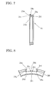
- FIGS. 1 to 3 of the drawings there is shown a shift device, which has a synchronizer and is adapted for a transmission of a motor vehicle, of a first preferred embodiment according to the present invention.
- the shift device includes an input shaft 10 connectable with a not-shown crank shaft of an engine via a not-shown clutch, a third gear 18, a fourth gear 20, and a synchronizer 2 placed between the third gear 18 and the fourth gear 20.
- the input shaft 10 is capable of transmitting drive power and acts as a shaft of the present invention.
- the third gear 18 and the fourth gear 20 act as a pair of speed gears of the present invention.
- the input shaft 10 is formed on its partial outer surface with splines 10a, which is engaged by splines 12a formed on an inner surface of cylindrical boss portion 12b of a hub 12, so that the input shaft 10 drives the hub 12 to rotate together with each other at the same speed.
- the hub 12 is fixed to the input shaft 10 by contacting at its one side portion with a large diameter portion of the input shaft 10 and also contacting at its other end portion with a bush 14, which is press-fitted onto an outer surface of a small diameter portion of the input shaft 10.
- the hub 12 has the boss portion 12b, a ring portion 12d arranged in coaxial with the boss portion 12b and outwardly in its radial direction, and a flange portion 12c connecting the boss portion 12b and the ring portion 12d and formed thinner in thickness than the boss portion 12b.
- Splines 12e are formed on the outer surface of the ring portion 12d and engage with splines 22a formed on an inner surface of a sleeve 22 so as to slide relative to each other in the axial direction.
- the sleeve 22 is formed with a circumferential groove 22b on its outer surface, in which a not-shown shift fork is partially inserted.
- the shift fork is capable of moving in the axial direction according to a not-shown shift lever operated by a driver or a not-shown actuator.
- the third gear 18 is freely rotatably supported through a bearing 16a at one side of the hub 12, and the fourth gear 20 is freely rotatably supported though a bearing 16b at the other side of the hub 12.
- the third gear 18 and the fourth gear 20 are in constant mesh with not-shown gears on an output shaft arranged in parallel to the input shaft 10, respectively.
- the third gear 18 is formed to integrally have splines 18a and an outer conical friction surface 18b at the hub 12 side thereof.
- the splines 18a are capable of engaging with the spline 22a of the sleeve 22 by moving the sleeve 22 to a third speed position.
- the outer conical friction surface 18b faces to an inner conical friction surface 24a of a synchronizer ring 24.
- the inner conical friction surface 24a corresponds to a friction surface of the present invention.
- the fourth gear 20 is formed to integrally have splines 20a and an outer conical friction surface 20b at the hub 12 side thereof.
- the splines 20a are capable of engaging wit the spline 22a of the sleeve 22 by moving the sleeve 22 to a fourth speed position.
- the outer conical friction surface 18b faces to an inner conical friction surface 24a of another synchronizer ring 24, which is arranged in symmetric with the synchronizer ring 24 at the third gear 18 side.
- the inner conical friction surface 24a corresponds to a friction surface of the present invention.
- the sleeve 22 is designed to have lengths and positional relationships with other parts so as to move to be shiftable among the third speed position, the fourth speed position, and a neutral position.
- the neutral position is between the third and fourth speed positions as shown in FIGS. 1 and 3, where the splines 22a of the sleeve 22 are not in mesh with the splines 18a and 20a of the third and fourth gears 18 and 20. Note that the splines 22a of the sleeve 22 is in constant mesh with the splines 12e of the ring portion 12d at the third speed, neutral and fourth speed positions.
- the synchronizer ring 24, the sleeve 22 and the splines 18a and 20a and the outer friction surfaces 18b and 20b of the third and fourth gears 18 and 20 constitute the synchronizer of the shift device.
- the above-constructed synchronizer 2 of the embodiment further has a force amplifying mechanism, which is constructed as below.
- the flange portion 12c and the ring portion 12d of the hub 12 are partially cut off at three portions to form three notch portions 12f, in each of which a thrust piece 26 is located as shown in FIGS. 1 to 3.
- the thrust pieces 26 are also located between the synchronizer rings 24 and 24 in the axial direction, and between the hub 12 and the sleeve 22 in the radial direction.
- the thrust pieces 26 are pushed outwardly in a radial direction by two springs 18, which are arranged in an inner space formed by the three thrust pieces 26.
- the notch portions 12f of the hub 12 are formed at four edges in the axial direction to have slanted surfaces 12g to 12j as shown in FIG. 5. These slanted surfaces 12g to 12j are designed to have a configuration to change directions of forces so that the thrust pieces 26 are pressed in the direction when the thrust pieces 26 contact with the slanted surfaces 12g to 12j of the hub 12 and rotating force is applied to the thrust pieces 26.
- the notch portions 12f are also formed at the boss portion 12b side with a seat surface 12k for receiving the spring 28.
- the splines 22a of the sleeve 22 are formed to have chamfers 22c and 22d at their axial both ends, three splines at three positions around a circumstance of the splines 22a of the sleeve 22 are formed inside thereof with projections 22g having slanted surfaces 22e and 22f.
- the projections 22g are engageable with the thrust piece 26.
- One spline of the three splines is has a projecting portion 22h at its axial central portion.
- each synchronizer ring 24 is formed on its inner peripheral surface with a conical friction surface 24a.
- the conical friction surfaces 24a of the synchronizer rings 24 are arranged so as to face the friction surfaces 18b and 20b of the third and fourth speed gears, respectively.
- the synchronizer rings 24 are also formed on its outer peripheral surface with three notch portions 24b, each of which has first end surfaces 24e and 24f, second end surfaces 24g and 24h and chamfers 24c and 24d connecting the first and second end surfaces 24e and 24g, 24f and 24h, respectively.
- a projection 24i is formed to have slanted surfaces 24j and 24k.
- the synchronizer ring 24 has a rear surface 241 at its hub 12 side.
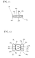
- the thrust pieces 26 are formed on its outer peripheral surfaces with a recess portion 26d having engageable slanted surfaces 26b and 26c, where a through-hole 26e at the center of the recess portion 26d is provided to connect with conical hole portion 26f.
- the conical hole portion 26f receives a ball 30 pressed by the spring 28.
- the recess portion 26d corresponds to the projection 22g of the sleeve 22, and is designed so that the projecting portion 22h of the sleeve 22 can be received in the through-hole 26e of the thrust pieces 26 when the thrust piece 26 is engaged with the projection 22g as shown in FIGS. 1 to 3.
- the thrust pieces 26 are formed to have an entirely curved portion as shown in FIG. 13, and are preferably formed as a part of a spherical shape. They have shapes like a rectangle, seen from an upper side (from an outer side in the radial direction), having four projections 26g to 26j at its corners.
- the projections 26g to 26j are formed with first slanted surfaces 26k to 26n at the outer side in the axial direction and with second slanted surfaces 26o to 26r at the inner side in the axial direction, respectively.
- the first slanted surfaces 26k to 26n correspond to the chamfers 24c and 24d of the synchronizer ring 24, and the second slanted surfaces 26o to 26r correspond to the slanted surfaces 12g to 12j, respectively, so that the corresponding surfaces thereof are contactable with each other.
- the thrust piece 26 is slightly swingable with respect to the hub 12, and accordingly the first slanted surfaces 26k to 26n and the second slanted surfaces 26o to 26r are formed to have a slightly circular arc surface with small rounded corners.
- two recesses 26t are provided at both axial end portions on an inner peripheral surface 26s of the thrust piece 26, so as to correspond to the projection 24i of the synchronizer ring 24.
- the projection 24i of the synchronizer ring 24 is received in one of the recesses 26t when the thrust piece 26 is moved inwardly in the radial direction.
- the sleeve 22 is positioned at a position shown in FIGS. 3 and 14, so that its splines 22a engage only with the splines 12e of the hub 12, not with the splines 24b of the synchronizer rings 24.
- the thrust pieces 26 are pushed outwardly in the radial direction by the springs 18, so that the thrust pieces 26 are engaged with the projections 22g of the sleeve 22 and the cut-off portions 12f of the hub 12.
- the second slanted surfaces 26o to 26r of the thrust pieces 26 are not in contact with the slanted surfaces 12g to 12j of the hub 12.
- the sleeve 22 is moved toward the third gear 18.
- the sleeve 22 and the thrust pieces 26, engaged with the sleeve 22, move together, so that, first, the ball 30 contacts with the rear surface 241 of the synchronizer ring 24, pressing the synchronizer ring 24 toward the third gear 18 with force corresponding to tension of the springs 30.
- friction is generated between the friction surface 24a of the synchronizer ring 24 and the friction surface 18b of the third gear 18.
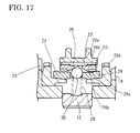
- the frictional torque generated therebetween rotates the synchronizer ring 24 with respect to the thrust pieces 26, thereby changing its state into a state shown in FIG. 16.
- the chamfers 24c of the synchronizer ring 24 contact with the second end surfaces 24g of the thrust pieces 26.
- the thrust pieces 26 are slightly moved toward the third gear 18, so that they are swingable in the notch portions 12f of the hub 12. Consequently, the thrust pieces 26 are pressed by the chamfers 24c of the synchronizer ring 24 to be slightly swung as shown in FIG. 16, and the first slanted surfaces 26k of the thrust pieces 26 contact with the slanted surfaces 12g of the hub 12.
- the projections 24g are somewhat out of the recesses 26t of the thrust pieces 26 as shown in FIG. 16 (FIG. 16 shows only one f projection 24g).
- the first slanted surfaces 26k of the thrust pieces 26 contact with the slanted surfaces 12g of the hub 12, and accordingly the friction torque transmitted through the chamfers 24c of the synchronizer ring 24 acts on the hub 12. Since the first slanted surfaces 26k and the slanted surfaces 12g are capable of changing rotational force due to friction torque to thrust, the friction torque generated by the rotational speed difference between the synchronizer ring 24 and the third gear 18 acts on the slanted surfaces 12g, thereby producing thrust by the first slanted surfaces 26k and the slanted surfaces 12g to press the thrust pieces 26 toward the third gear 18.
- the thrust pieces 26 applies axial resultant force Fm + Ft on the chamfers 24c of the synchronizer ring 24, where Fm is thrust pressed by the slanted surfaces 22e of the sleeve 22 and Ft is thrust generated by the first slanted surfaces 26k of the thrust pieces 26 and the slanted surfaces 12g of the hub 12.
- the thrust Ft acts as self-servo force generated by the friction torque, and is added to the thrust Fm to press the synchronizer ring 24. This can reduce operating force by an amount of the thrust Ft than that of a shift device without a self-servo function.
- Angles of the chamfers 24c of the synchronizer ring 24 are set properly so that the thrust pieces 26 can be prevented from moving forward in the axial direction by the synchronizer ring 24 as long as the rotational speed difference is generated between the synchronizer ring 24 and the third gear 18. Therefore, the thrust pieces 26 cannot move to the splines 18a of the third gear 18, and keep pressing the synchronizer ring 24 to function the self-servo operation, adding the self-servo thrust Ft.
- This self-servo operation gradually decreases the rotational speed difference between the synchronizer ring 24 and the third gear 18 into substantially zero, namely diminishing the friction torque into substantially zero.
- the thrust pieces 26 rotate the synchronizer ring 24 relatively thereto toward its neutral position by the first slanted surfaces 26k, thereby being allowed to move forward toward the third gear 18.
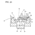
- the sleeve 22 moves further forward for its splines 22a to engage with the splines 18a of the third gear 18 which are rotating at the substantially same speed as that of the sleeve 22.
- This engagement brings the end of the shift operation.
- the projections 22h of the sleeve 22 contact with the engageable slanted surfaces 26b of the thrust pieces 26 as shown in fig. 20.
- the thrust pieces 26 are restricted from being moved toward the hub 12 by the sleeve 22, which ensures to prevent unexpected occurrence in which the thrust pieces 26 move toward the fourth gear 20 in a state where the sleeve 22 engages with the third gear 18.
- a shift operation to the fourth speed is similar to that to the third speed, although movements of the parts are symmetric to those in the shift operation to the third speed.
- the shift device of the embodiment has the following advantages.
- press force necessary for the sleeve 24 is smaller than that necessary for a shift device with a normal Borg-Warner type synchronizer. This means that the shift device of the embodiment can improve its synchronizing ability.
- the hub 12 needs only the slanted surfaces 12g to 12j formed on the cut-off portions 12f thereof in the axial direction, and accordingly can be produced by using a sintering process, a sinter forging process, or the like.
- the thrust pieces 26 are formed to have the first slanted surfaces 26k to 26n and the second slanted surfaces 26o to 26r at their four corners so that the thrust pieces 26 are engaged with the sleeve 22 during a synchronizing operation and they are disengaged from each other before the sleeve 22 is engaged with the speed gear after the synchronizing operation. Therefore, the shift device of the embodiment can decrease manufacturing costs of the hub 12.
- the shift device with the synchronizer is mounted on the input shaft 10, but it may be mounted in an output shaft.
- the slanted surfaces 12g to 12j of the hub 12 and the slanted surfaces 26k to 26r of the thrust pieces 26 may be formed in a tapered surface, a helical surface, and others.
- the synchronizer ring 24 may have an oil groove on its inner friction surface in order to increase a friction coefficient of the friction surface, and may be made of material for improving synchronizing ability.
- the shift device with the synchronizer may be applied to a multi-corn type synchronizer, which has several friction surfaces.
- the shift device may be manually operated, or mechanically operated by an actuator.
- the speed gear employs the third gear 18 and the fourth gear 20 in the embodiment, but may be other speed gear.
Landscapes
- Engineering & Computer Science (AREA)
- General Engineering & Computer Science (AREA)
- Mechanical Engineering (AREA)
- Mechanical Operated Clutches (AREA)
Applications Claiming Priority (1)
| Application Number | Priority Date | Filing Date | Title |
|---|---|---|---|
| JP2006049470A JP4716114B2 (ja) | 2006-02-27 | 2006-02-27 | 変速機用同期装置 |
Publications (3)
| Publication Number | Publication Date |
|---|---|
| EP1826431A2 true EP1826431A2 (de) | 2007-08-29 |
| EP1826431A3 EP1826431A3 (de) | 2009-04-29 |
| EP1826431B1 EP1826431B1 (de) | 2012-10-03 |
Family
ID=38050883
Family Applications (1)
| Application Number | Title | Priority Date | Filing Date |
|---|---|---|---|
| EP07103050A Expired - Fee Related EP1826431B1 (de) | 2006-02-27 | 2007-02-26 | Schaltvorrichtung mit Synchronisator für Getriebe |
Country Status (5)
| Country | Link |
|---|---|
| US (1) | US7717246B2 (de) |
| EP (1) | EP1826431B1 (de) |
| JP (1) | JP4716114B2 (de) |
| KR (1) | KR101328817B1 (de) |
| CN (1) | CN101029683B (de) |
Cited By (11)
| Publication number | Priority date | Publication date | Assignee | Title |
|---|---|---|---|---|
| EP1900956A2 (de) * | 2006-09-18 | 2008-03-19 | Hofer-PDC-Gmbh | Getriebesynchronisierung, insbesondere in der Form einer Servo-Synchronisierung |
| WO2008101729A3 (de) * | 2007-02-22 | 2009-12-03 | Hoerbiger Synchrontechnik Gmbh & Co. Kg | Schaltkupplungsanordnung |
| WO2010015011A1 (de) * | 2008-08-06 | 2010-02-11 | Miba Sinter Austria Gmbh | Kraftverstärkungselement |
| EP2169250A1 (de) * | 2008-09-29 | 2010-03-31 | hofer powertrain GmbH | Doppelkupplungsgetriebe |
| EP2302245A1 (de) * | 2009-09-28 | 2011-03-30 | Kyowa Metal Works Co., Ltd | Schaltvorrichtung mit Synchronisierung |
| EP2236847A3 (de) * | 2009-04-03 | 2012-01-04 | Kyowa Metal Works Co., Ltd | Für ein Getriebe angepasste Schaltvorrichtung |
| CN101713449B (zh) * | 2009-05-07 | 2012-06-20 | 浙江吉利汽车研究院有限公司 | 机械式变速器中的同步器 |
| CN106415076A (zh) * | 2014-06-03 | 2017-02-15 | 斯堪尼亚商用车有限公司 | 变速箱中的结构 |
| CN107420452A (zh) * | 2017-08-28 | 2017-12-01 | 陕西法士特汽车传动集团有限责任公司 | 一种退挡增力锁环式惯性同步器 |
| WO2018095724A1 (de) * | 2016-11-22 | 2018-05-31 | GETRAG B.V. & Co. KG | Servosynchronisationsvorrichtung für ein getriebe eines kraftfahrzeugs |
| AT508295B1 (de) * | 2009-06-05 | 2019-04-15 | Miba Sinter Austria Gmbh | Getriebe-synchronisationsvorrichtung |
Families Citing this family (27)
| Publication number | Priority date | Publication date | Assignee | Title |
|---|---|---|---|---|
| JP4609796B2 (ja) * | 2005-08-05 | 2011-01-12 | 協和合金株式会社 | 変速機用同期装置 |
| AT506205B1 (de) * | 2007-12-18 | 2011-11-15 | Miba Sinter Austria Gmbh | Kraftverstärkungselement |
| JP2009236202A (ja) | 2008-03-27 | 2009-10-15 | Kyowa Metal Work Co Ltd | 変速機用同期装置 |
| CN101655140B (zh) * | 2009-09-17 | 2011-07-20 | 上海汽车变速器有限公司 | 具有防脱出集成滑块的同步器 |
| DE102009048806A1 (de) * | 2009-10-08 | 2011-04-14 | Hoerbiger Antriebstechnik Gmbh | Synchronisiereinrichtung eines Schaltgetriebes |
| US9719564B2 (en) * | 2009-12-22 | 2017-08-01 | Fca Us Llc | Synchronizer re-energization for improved cold shift comfort |
| DE102010032299A1 (de) * | 2010-07-26 | 2012-01-26 | Hoerbiger Antriebstechnik Holding Gmbh | Synchronisationseinheit eines Schaltgetriebes |
| CN101929540B (zh) * | 2010-08-30 | 2012-11-21 | 赵孝生 | 一种锁环式惯性同步器 |
| CN101956810A (zh) * | 2010-10-19 | 2011-01-26 | 泰州市海博汽车科技有限公司 | 一种可减小换档力的汽车同步器 |
| JP5708791B2 (ja) * | 2011-03-29 | 2015-04-30 | トヨタ自動車株式会社 | 車両の噛合歯車 |
| CN102606713B (zh) * | 2012-03-30 | 2016-01-20 | 长城汽车股份有限公司 | 一种倒挡同步装置 |
| CN102644723B (zh) * | 2012-04-24 | 2015-04-08 | 陕西法士特齿轮有限责任公司 | 一种锁环式同步装置及其同步方法 |
| DE102012015006A1 (de) * | 2012-07-28 | 2014-01-30 | GM Global Technology Operations LLC (n. d. Gesetzen des Staates Delaware) | Kuppelvorrichtung mit einer Schaltmuffe fürein Schaltgetriebe |
| CN103216543B (zh) * | 2013-04-18 | 2015-04-08 | 柳州上汽汽车变速器有限公司 | 汽车同步器 |
| FR3006406B1 (fr) * | 2013-05-29 | 2016-12-02 | Technoboost | Dispositif passif de lubrification de la mecanique interne d'une boite vitesses |
| CN103352931B (zh) * | 2013-07-19 | 2015-11-04 | 重庆青山工业有限责任公司 | 一种汽车变速器同步器 |
| JP6183999B2 (ja) * | 2013-07-24 | 2017-08-23 | 協和合金株式会社 | 変速機用同期装置 |
| CN103453041B (zh) * | 2013-08-29 | 2016-03-16 | 无锡贺安特动力科技有限公司 | 无齿同步环及同步器 |
| CN103671838B (zh) * | 2013-11-19 | 2016-01-13 | 惠州市毅隆机电设备有限公司 | 一种浮动拨叉传动机构 |
| DE102016217096A1 (de) * | 2016-09-08 | 2018-03-08 | Audi Ag | Verfahren zum Synchronisieren zweier Antriebselemente eines Antriebsstrangs eines Kraftfahrzeugs, sowie Antriebsstrang für ein Kraftfahrzeug |
| DE102017112030B3 (de) | 2017-06-01 | 2018-08-30 | Schaeffler Technologies AG & Co. KG | Synchronring mit elastischer Anbindung |
| CN107091283A (zh) * | 2017-06-30 | 2017-08-25 | 天津天海同步科技有限公司 | 一种变速器同步装置的传扭滑动型花键系统 |
| CN109398590A (zh) * | 2018-11-30 | 2019-03-01 | 宁波工程学院 | 变速链轮组件 |
| KR20200069916A (ko) * | 2018-12-07 | 2020-06-17 | 현대자동차주식회사 | 변속기용 동기장치 |
| SE543707C2 (en) * | 2019-05-17 | 2021-06-22 | Scania Cv Ab | Method and arrangement for controlling a vehicle powertrain to overcome, or avoid, a cog-to-cog condition |
| KR102532461B1 (ko) * | 2019-09-18 | 2023-05-12 | 한국자동차연구원 | 전기자동차용 변속장치 |
| DE102019128160B9 (de) * | 2019-10-18 | 2021-01-21 | Höhn Gmbh | Zweiganggetriebe für Elektromotoren |
Family Cites Families (12)
| Publication number | Priority date | Publication date | Assignee | Title |
|---|---|---|---|---|
| US3548983A (en) * | 1968-05-15 | 1970-12-22 | Nissan Motor | Synchronizing mechanism in the transmission of constant-mesh type in an automotive vehicle |
| JPH0143552Y2 (de) * | 1984-11-02 | 1989-12-18 | ||
| DE3622464C1 (de) * | 1986-07-04 | 1987-12-17 | Getrag Getriebe- Und Zahnradfabrik Gmbh, 7140 Ludwigsburg, De | |
| US5588516A (en) * | 1993-12-27 | 1996-12-31 | Eaton Corporation | Synchronizer with self-energizing |
| FR2733560B1 (fr) * | 1995-04-28 | 1997-06-13 | Renault | Dispositif de synchronisation pour boite de vitesses mecanique |
| GB2357125A (en) * | 1999-12-08 | 2001-06-13 | Eaton Corp | Synchronizer with a resilient force limiting ramp members and blocker teeth |
| JP2002276689A (ja) * | 2001-03-19 | 2002-09-25 | Aisin Ai Co Ltd | 同期装置 |
| GB0116676D0 (en) * | 2001-07-07 | 2001-08-29 | Eaton Corp | Synchronizer |
| GB0302850D0 (en) * | 2003-02-07 | 2003-03-12 | Eaton Corp | Synchronizer |
| DE20314492U1 (de) * | 2003-09-17 | 2003-12-11 | Rother, Werner | Ventilator mit Filtervorrichtung |
| JP2005114156A (ja) * | 2003-09-19 | 2005-04-28 | Nissan Motor Co Ltd | 変速機の同期装置 |
| JP4609796B2 (ja) * | 2005-08-05 | 2011-01-12 | 協和合金株式会社 | 変速機用同期装置 |
-
2006
- 2006-02-27 JP JP2006049470A patent/JP4716114B2/ja active Active
-
2007
- 2007-02-26 US US11/710,509 patent/US7717246B2/en not_active Expired - Fee Related
- 2007-02-26 EP EP07103050A patent/EP1826431B1/de not_active Expired - Fee Related
- 2007-02-27 CN CN2007100803024A patent/CN101029683B/zh not_active Expired - Fee Related
- 2007-02-27 KR KR1020070019701A patent/KR101328817B1/ko not_active IP Right Cessation
Non-Patent Citations (1)
| Title |
|---|
| None |
Cited By (15)
| Publication number | Priority date | Publication date | Assignee | Title |
|---|---|---|---|---|
| EP1900956A2 (de) * | 2006-09-18 | 2008-03-19 | Hofer-PDC-Gmbh | Getriebesynchronisierung, insbesondere in der Form einer Servo-Synchronisierung |
| CN101675262B (zh) * | 2007-02-22 | 2012-12-26 | 贺尔碧格同步技术有限公司 | 离合器总成 |
| WO2008101729A3 (de) * | 2007-02-22 | 2009-12-03 | Hoerbiger Synchrontechnik Gmbh & Co. Kg | Schaltkupplungsanordnung |
| US8511451B2 (en) | 2007-02-22 | 2013-08-20 | Hoerbiger Synchron Technik Gmbh & Co. Kg | Clutch assembly |
| WO2010015011A1 (de) * | 2008-08-06 | 2010-02-11 | Miba Sinter Austria Gmbh | Kraftverstärkungselement |
| US8528435B2 (en) | 2008-08-06 | 2013-09-10 | Miba Sinter Austria Gmbh | Power assist element |
| EP2169250A1 (de) * | 2008-09-29 | 2010-03-31 | hofer powertrain GmbH | Doppelkupplungsgetriebe |
| EP2236847A3 (de) * | 2009-04-03 | 2012-01-04 | Kyowa Metal Works Co., Ltd | Für ein Getriebe angepasste Schaltvorrichtung |
| CN101713449B (zh) * | 2009-05-07 | 2012-06-20 | 浙江吉利汽车研究院有限公司 | 机械式变速器中的同步器 |
| AT508295B1 (de) * | 2009-06-05 | 2019-04-15 | Miba Sinter Austria Gmbh | Getriebe-synchronisationsvorrichtung |
| EP2302245A1 (de) * | 2009-09-28 | 2011-03-30 | Kyowa Metal Works Co., Ltd | Schaltvorrichtung mit Synchronisierung |
| CN106415076A (zh) * | 2014-06-03 | 2017-02-15 | 斯堪尼亚商用车有限公司 | 变速箱中的结构 |
| WO2018095724A1 (de) * | 2016-11-22 | 2018-05-31 | GETRAG B.V. & Co. KG | Servosynchronisationsvorrichtung für ein getriebe eines kraftfahrzeugs |
| CN107420452A (zh) * | 2017-08-28 | 2017-12-01 | 陕西法士特汽车传动集团有限责任公司 | 一种退挡增力锁环式惯性同步器 |
| CN107420452B (zh) * | 2017-08-28 | 2024-04-09 | 陕西法士特汽车传动集团有限责任公司 | 一种退挡增力锁环式惯性同步器 |
Also Published As
| Publication number | Publication date |
|---|---|
| US7717246B2 (en) | 2010-05-18 |
| CN101029683B (zh) | 2011-04-13 |
| KR101328817B1 (ko) | 2013-11-13 |
| EP1826431B1 (de) | 2012-10-03 |
| JP4716114B2 (ja) | 2011-07-06 |
| JP2007225071A (ja) | 2007-09-06 |
| US20070199786A1 (en) | 2007-08-30 |
| CN101029683A (zh) | 2007-09-05 |
| KR20070089093A (ko) | 2007-08-30 |
| EP1826431A3 (de) | 2009-04-29 |
Similar Documents
| Publication | Publication Date | Title |
|---|---|---|
| EP1826431B1 (de) | Schaltvorrichtung mit Synchronisator für Getriebe | |
| EP1750025B1 (de) | Schaltungsvorrichtung mit Synchronisierungsvorrichtung für Antrieb | |
| EP2306039B1 (de) | Für ein Getriebe angepasste Schaltvorrichtung | |
| EP2626583B1 (de) | Schaltvorrichtung mit Synchronisator | |
| US20040163917A1 (en) | Synchronizer for speed reducer | |
| EP2236847B1 (de) | Für ein Getriebe angepasste Schaltvorrichtung | |
| US20070289835A1 (en) | Synchronizer mechanism for transmission | |
| EP2725250B1 (de) | Schaltvorrichtung mit Synchronisator | |
| JP6183999B2 (ja) | 変速機用同期装置 | |
| JP2012057786A (ja) | 変速機の同期結合機構 | |
| US8307969B2 (en) | Shift device with synchronizer | |
| JP2008075672A (ja) | 変速機 | |
| JP2009156327A (ja) | 自動車用変速機 | |
| EP2302245A1 (de) | Schaltvorrichtung mit Synchronisierung | |
| JP6204156B2 (ja) | 変速機用同期装置 | |
| JP2009036217A (ja) | 変速機の同期装置 | |
| JPH05118346A (ja) | 同期噛合装置 | |
| PH12013000047A1 (en) | Shift device with synchronizer | |
| JPH02221720A (ja) | トリプルコーン型同期装置 | |
| GB2538077A (en) | Shift device with synchronizer | |
| PH12013000321A1 (en) | Shift device with synchronizer |
Legal Events
| Date | Code | Title | Description |
|---|---|---|---|
| PUAI | Public reference made under article 153(3) epc to a published international application that has entered the european phase |
Free format text: ORIGINAL CODE: 0009012 |
|
| AK | Designated contracting states |
Kind code of ref document: A2 Designated state(s): AT BE BG CH CY CZ DE DK EE ES FI FR GB GR HU IE IS IT LI LT LU LV MC NL PL PT RO SE SI SK TR |
|
| AX | Request for extension of the european patent |
Extension state: AL BA HR MK YU |
|
| PUAL | Search report despatched |
Free format text: ORIGINAL CODE: 0009013 |
|
| AK | Designated contracting states |
Kind code of ref document: A3 Designated state(s): AT BE BG CH CY CZ DE DK EE ES FI FR GB GR HU IE IS IT LI LT LU LV MC NL PL PT RO SE SI SK TR |
|
| AX | Request for extension of the european patent |
Extension state: AL BA HR MK RS |
|
| 17P | Request for examination filed |
Effective date: 20091008 |
|
| 17Q | First examination report despatched |
Effective date: 20091120 |
|
| AKX | Designation fees paid |
Designated state(s): DE FR GB |
|
| GRAC | Information related to communication of intention to grant a patent modified |
Free format text: ORIGINAL CODE: EPIDOSCIGR1 |
|
| GRAP | Despatch of communication of intention to grant a patent |
Free format text: ORIGINAL CODE: EPIDOSNIGR1 |
|
| GRAS | Grant fee paid |
Free format text: ORIGINAL CODE: EPIDOSNIGR3 |
|
| GRAA | (expected) grant |
Free format text: ORIGINAL CODE: 0009210 |
|
| AK | Designated contracting states |
Kind code of ref document: B1 Designated state(s): DE FR GB |
|
| REG | Reference to a national code |
Ref country code: GB Ref legal event code: FG4D |
|
| REG | Reference to a national code |
Ref country code: DE Ref legal event code: R096 Ref document number: 602007025815 Country of ref document: DE Effective date: 20121129 |
|
| PLBE | No opposition filed within time limit |
Free format text: ORIGINAL CODE: 0009261 |
|
| STAA | Information on the status of an ep patent application or granted ep patent |
Free format text: STATUS: NO OPPOSITION FILED WITHIN TIME LIMIT |
|
| 26N | No opposition filed |
Effective date: 20130704 |
|
| REG | Reference to a national code |
Ref country code: DE Ref legal event code: R097 Ref document number: 602007025815 Country of ref document: DE Effective date: 20130704 |
|
| REG | Reference to a national code |
Ref country code: FR Ref legal event code: PLFP Year of fee payment: 10 |
|
| REG | Reference to a national code |
Ref country code: FR Ref legal event code: PLFP Year of fee payment: 11 |
|
| REG | Reference to a national code |
Ref country code: FR Ref legal event code: PLFP Year of fee payment: 12 |
|
| PGFP | Annual fee paid to national office [announced via postgrant information from national office to epo] |
Ref country code: DE Payment date: 20170210 Year of fee payment: 11 Ref country code: FR Payment date: 20170330 Year of fee payment: 12 |
|
| PGFP | Annual fee paid to national office [announced via postgrant information from national office to epo] |
Ref country code: GB Payment date: 20170214 Year of fee payment: 11 |
|
| REG | Reference to a national code |
Ref country code: DE Ref legal event code: R119 Ref document number: 602007025815 Country of ref document: DE |
|
| GBPC | Gb: european patent ceased through non-payment of renewal fee |
Effective date: 20180226 |
|
| PG25 | Lapsed in a contracting state [announced via postgrant information from national office to epo] |
Ref country code: DE Free format text: LAPSE BECAUSE OF NON-PAYMENT OF DUE FEES Effective date: 20180901 |
|
| PG25 | Lapsed in a contracting state [announced via postgrant information from national office to epo] |
Ref country code: GB Free format text: LAPSE BECAUSE OF NON-PAYMENT OF DUE FEES Effective date: 20180226 |
|
| PG25 | Lapsed in a contracting state [announced via postgrant information from national office to epo] |
Ref country code: FR Free format text: LAPSE BECAUSE OF NON-PAYMENT OF DUE FEES Effective date: 20190228 |