EP1815618B1 - Datenkommunikationssystem - Google Patents
Datenkommunikationssystem Download PDFInfo
- Publication number
- EP1815618B1 EP1815618B1 EP05798421A EP05798421A EP1815618B1 EP 1815618 B1 EP1815618 B1 EP 1815618B1 EP 05798421 A EP05798421 A EP 05798421A EP 05798421 A EP05798421 A EP 05798421A EP 1815618 B1 EP1815618 B1 EP 1815618B1
- Authority
- EP
- European Patent Office
- Prior art keywords
- optical
- signal
- base station
- data signal
- uplink
- Prior art date
- Legal status (The legal status is an assumption and is not a legal conclusion. Google has not performed a legal analysis and makes no representation as to the accuracy of the status listed.)
- Active
Links
- 238000004891 communication Methods 0.000 title claims description 35
- 230000003287 optical effect Effects 0.000 claims description 154
- 239000013307 optical fiber Substances 0.000 claims description 26
- 230000005540 biological transmission Effects 0.000 claims description 16
- 238000000034 method Methods 0.000 claims description 10
- 238000012546 transfer Methods 0.000 claims description 6
- 238000006243 chemical reaction Methods 0.000 claims description 5
- 230000005855 radiation Effects 0.000 description 12
- 238000013461 design Methods 0.000 description 11
- 239000002131 composite material Substances 0.000 description 6
- 230000000694 effects Effects 0.000 description 6
- 230000001413 cellular effect Effects 0.000 description 4
- 230000003321 amplification Effects 0.000 description 3
- 230000001934 delay Effects 0.000 description 3
- 230000003111 delayed effect Effects 0.000 description 3
- 239000003989 dielectric material Substances 0.000 description 3
- 239000000463 material Substances 0.000 description 3
- 238000003199 nucleic acid amplification method Methods 0.000 description 3
- 239000000969 carrier Substances 0.000 description 2
- 239000000835 fiber Substances 0.000 description 2
- 238000001914 filtration Methods 0.000 description 2
- 238000005286 illumination Methods 0.000 description 2
- 238000003780 insertion Methods 0.000 description 2
- 230000037431 insertion Effects 0.000 description 2
- 238000010295 mobile communication Methods 0.000 description 2
- 239000004810 polytetrafluoroethylene Substances 0.000 description 2
- 229920001343 polytetrafluoroethylene Polymers 0.000 description 2
- 230000007704 transition Effects 0.000 description 2
- 239000006096 absorbing agent Substances 0.000 description 1
- 239000011358 absorbing material Substances 0.000 description 1
- 210000004027 cell Anatomy 0.000 description 1
- 210000003850 cellular structure Anatomy 0.000 description 1
- 238000002955 isolation Methods 0.000 description 1
- 239000002184 metal Substances 0.000 description 1
- 230000001151 other effect Effects 0.000 description 1
- 235000014366 other mixer Nutrition 0.000 description 1
- 230000000717 retained effect Effects 0.000 description 1
- 238000000926 separation method Methods 0.000 description 1
Images


Classifications
-
- H—ELECTRICITY
- H04—ELECTRIC COMMUNICATION TECHNIQUE
- H04B—TRANSMISSION
- H04B10/00—Transmission systems employing electromagnetic waves other than radio-waves, e.g. infrared, visible or ultraviolet light, or employing corpuscular radiation, e.g. quantum communication
- H04B10/25—Arrangements specific to fibre transmission
- H04B10/2575—Radio-over-fibre, e.g. radio frequency signal modulated onto an optical carrier
- H04B10/25752—Optical arrangements for wireless networks
- H04B10/25753—Distribution optical network, e.g. between a base station and a plurality of remote units
-
- H—ELECTRICITY
- H04—ELECTRIC COMMUNICATION TECHNIQUE
- H04B—TRANSMISSION
- H04B10/00—Transmission systems employing electromagnetic waves other than radio-waves, e.g. infrared, visible or ultraviolet light, or employing corpuscular radiation, e.g. quantum communication
- H04B10/25—Arrangements specific to fibre transmission
- H04B10/2575—Radio-over-fibre, e.g. radio frequency signal modulated onto an optical carrier
- H04B10/25752—Optical arrangements for wireless networks
Definitions
- the present invention relates to data communications and in particular to a method and apparatus for communicating data between terminal devices, at least one of which is a mobile terminal device.
- EP1357683A describes a hybrid fibre-radio system in which a local oscillator signal is sent from a base station to a remote antenna unit for use in a uplink signal up-converter. That specification and US-A6674969 also disclose the generation of downlink optical downlink signals using injection-locked lasers.
- a base station operable to communicate data over a two-way communications channel established with a mobile terminal unit, by way of at least one antenna unit operable to communicate wirelessly with the mobile terminal unit, wherein the base station is operable to communicate with said at least one antenna unit over an optical fibre link, the base station comprising:
- both the first and second optical modulators are Mach-Zehnder optical modulators.
- the first Mach-Zehnder optical modulator is biased at the minimum of its transfer characteristic so that the optical oscillator signal includes an oscillator signal having twice the frequency of the radio frequency oscillator signal used to modulate the optical carrier.
- the second Mach-Zehnder optical modulator is biased at the quadrature point of its transfer characteristic.
- the invention also provides a communication system comprising a base station as set forth above.
- the system may include an antenna unit, comprising:
- the antenna unit may further comprise a receiver for receiving a radio frequency data signal transmitted by a mobile terminal unit; a converter for converting the received radio frequency data signal, using the local oscillator signal, into an intermediate frequency data signal; and an optical transmitter for generating an uplink optical data signal to convey the intermediate frequency data signal to the base station.
- the system may also comprise a mobile terminal unit comprising:
- the signal conversion means comprise:
- Preferred embodiments of the present invention relate to an apparatus designed to provide a communications path between terminals, at least one of which is a mobile terminal unit.
- one or more high bandwidth communications channels are to be provided to enable wireless communication between a central terminal and one or more mobile devices, for example high-definition television cameras moving within a relatively enclosed environment such as a large TV studio or film set.
- highfrequency signals preferably of the order of 55-65GHz, which when communicated wirelessly, are subject to attenuation, distortion and other effects. Such effects are not typically encountered, or not encountered to the same extent, in conventional mobile communications systems which operate with lower frequency signals and in more open environments.
- a preferred apparatus comprises a base station and one or more remote antenna units (RAUs).
- RAUs remote antenna units
- a preferred mobile terminal unit transmit/receive interface will also be described for use with the preferred base station and remote antenna units.
- a base station 100 is arranged to communicate with one or more mobile data terminals 120, 125 by means of RAUs 110.
- Each RAU 110 is linked to the base station 100 by means of a downlink optical fibre 115 and an uplink optical fibre 118 in a fibre-radio architecture.
- Optical fibre transmission is used for communication between the base station 100 and RAUs 110, rather than an electrical transmission line (e.g. coaxial cable or electrical waveguide) or radio frequency (RF) transmission. This is particularly relevant at frequencies of the order of 60GHz, where electrical waveguide insertion loss is ⁇ 1.5dB/m and attenuation is approximately 12dB/km in free space.
- the base station 100 is arranged to modulate data signals received for example from a central terminal unit 105 or other terminal device and to transmit them optically, with low loss, to each of the RAUs 110 over the downlink optical fibres 115.
- Each of the RAUs 110 is arranged to convert the received optical signals into millimetre-wave signals for wireless transmission from their antennae.
- a target mobile data terminal 120, 125 moving within the area of radio coverage 130 of one or more of the RAUs 110 is then able to receive the transmitted signal.
- a radio-frequency signal transmitted by a mobile data terminal 120, 125 may be received by one or more RAUs 110.
- Each receiving RAU 110 is arranged to down-convert the received signal into an intermediate frequency (IF) data signal and to optically transmit the IF data signal over the respective uplink optical fibre 118 for reception by the base station 100. After demodulating the optically carried IF data signal the base station 100 outputs the resultant signal.
- IF intermediate frequency
- downlink 115 and uplink 118 optical fibre transmission lines are specified for simplicity, it is possible to combine downlink and uplink transmission lines between the base station 100 and an RAU 110 in a single optical fibre through use of appropriate multiplexing and modulation techniques and interfaces to split and combine fibres at the base station 100.
- a number of RAUs 110 with overlapping radio coverage areas 130 are arranged to form a single-frequency cellular structure using a different frequency for each of the mobile data terminals 120, 125.
- This is in contrast to conventional cellular radio systems in which a different frequency would be allocated for use by each RAU 110 to communicate with mobile data terminals 120, 125 moving within its area of radio coverage 130.
- use of a single frequency per mobile in preferred embodiments of the present invention avoids the need for a control system that would otherwise be needed, as in a conventional cellular radio system, to manage the handover of mobile data terminals 120, 125 as they move from the radio coverage area 130 and hence the communication frequency of one RAU 110 to those of another. This helps to ensure continuous communication with no interruption (essential for the transmission of real-time high data rate digital video signals, for example), often not possible with conventional multiple frequency cellular radio systems where brief interruptions are often experienced as a mobile changes its frequency when it moves between cells.
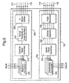
- the base station 100 is seen to comprise two main sections: a downlink transmitting interface 200 and an uplink receiving interface 245. Optical outputs from the downlink interface 200 and optical inputs to the uplink interface 245 are joined by means of an appropriate interface to the optical fibres 115 and 118 respectively linking each of the RAUs 110 to the base station 100.
- Data signals intended for a particular target mobile data terminal 120, 125 are received by the downlink transmitting interface 200 of the base station 100 where a number of modulators 205 are provided, each one dedicated to modulating input data signals in respect of a different data channel.
- a data channel may be used to communicate with one or more mobile terminal units 120, 125 according to the bandwidth requirements of those terminals.
- a single mobile terminal unit 120, 125 would require the entire bandwidth of a data channel for its own use, at least in an uplink direction.
- the base station 100 would be equipped to provide as many data channels as required by the particular application.
- limitations in frequency availability would ultimately limit the number of channels that may be provided.
- use of the 55-65GHz band provides sufficient bandwidth to handle a number of high data rate duplex channels.
- the modulated input signal is input to a downlink signal converter 210 where modulated signals for the respective data channel are converted to a predetermined frequency allocated specifically for the channel.
- the converted signal is then input to an optical transmitter and local oscillator 215 arranged to generate a downlink optical signal, preferably comprising an optical oscillator signal that is modulated by the converted input signal for transmission to the RAUs 110.
- the downlink optical signal output by the optical transmitter 215 includes a separate local oscillator signal that is then available for use, after isolation, by each receiving RAU 110, so avoiding the need to deploy an oscillator of the same frequency at each RAU 110. This reduces complex and bulky circuitry for generating and controlling a local oscillator signal within each RAU 110.
- the RAUs 110 are preferably designed to be small and compact so that they may be placed for example in environments, e.g. lamp posts in certain applications, where the temperature may vary significantly and may make an LO signal unstable.
- the downlink optical signal is input to an optical splitter 220 where it is divided and injected into each of the downlink optical fibre links 115 by means of an appropriate interface to be conveyed to each of the RAUs 110.
- an alternative technique for dividing the downlink optical signal may be implemented in which lower-order splitters, e.g. 1:4, are deployed in a cascaded arrangement, with erbium-doped fibre amplifiers being used to boost the signal if required.
- lower-order splitters e.g. 1:4
- erbium-doped fibre amplifiers being used to boost the signal if required.
- an initial splitter 220 at the base station 100 may be linked to remote splitters located nearer to the particular RAUs 110 being served to further sub-divide the signals.
- any signals received by one or more RAUs 110 from a mobile data terminal 120, 125 are converted and forwarded to the base station 100 over the uplink optical fibres 118 to arrive at the uplink receiving interface 245.
- the uplink receiving interface 245 includes a set of photo-receivers 225, one photo-receiver for each uplink optical fibre 118, which detects and converts uplink optical signals arriving over the uplink optical fibres 118 into IF signals for input to a channel separator 230.
- Uplink optical signals may comprise a combination of signals for one or more data channels which need to be separated by the base station 100.
- the channel separator 230 is therefore designed to separate the signals for each data channel (and hence for the different mobile data terminals 120, 125) on the basis that the signal for each data channel has a different predetermined frequency. Separated signals for each channel are then input to uplink signal converters 235 where the signals at their respective predetermined frequencies are converted for input to demodulators 240, a different demodulator 240 for each data channel. The demodulated output of each demodulator 235 forms the output from the base station 100, for example to the central terminal unit 105.
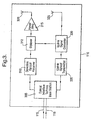
- an RAU 110 is provided with a downlink optical receiver 310 and an uplink optical transmitter 335, each linked by means of an optical interface 305 to the downlink optical fibre 115 and uplink optical fibre 118 respectively that connect the RAU 110 to the base station 100.
- the downlink optical receiver 310 is arranged to receive downlink optical signals transmitted by the base station optical transmitter and local oscillator 215 and to convert the received optical signals into radio frequency (RF) signals.
- the RF signals are input to a diplexer 312 arranged to separate the local oscillator signal generated by the base station optical transmitter 215 from the data signals for one or more data channels.
- the data signals output by the diplexer 312 are amplified by an amplifier 315 and fed to an antenna 320 for wireless transmission by the RAU 110.
- any RF signal transmitted by a mobile data terminal 120, 125 and received at an antenna 325 is passed to an uplink signal converter 330 arranged to convert the received RF signal into an intermediate frequency (IF) data signal.
- the uplink signal converter 330 uses the local oscillator signal separated by the diplexer 312 to convert the received RF signal into the IF data signal which in turn is passed to the uplink optical transmitter 335 to generate an uplink optical signal for transmission to the base station 100 over the uplink optical fibre 118.
- the uplink optical transmitter 335 transmits the IF data signal either by directly modulating a laser diode or by modulating the light from a (CW) laser diode in an external optical modulator.
- wavelength division multiplexing at the RAU 110 and wavelength division demultiplexing at the base station 100 it may be more convenient to use wavelength division multiplexing at the RAU 110 and wavelength division demultiplexing at the base station 100 so that multiple uplink optical signals may be combined onto a single uplink optical fibre 118 serving all the RAUs 110, or at least onto a reduced number of uplink optical fibres 118.
- the laser diode used in the uplink optical transmitter 335 would need to be selected so as to emit light of a wavelength compatible with the wavelength division multiplexer and with the associated channel spacing.
- Figure 3 shows a different antenna (320) being used at an RAU 110 for transmitting signals to that (325) used for receiving signals, the same physical antenna may be used for both transmitting and receiving.
- a different predetermined frequency is allocated to each data channel provided by the base station 100 and RAUs 110.
- the use of a different frequency per data channel provides one of the preferred elements in embodiments of the present invention that enables a single frequency (per mobile data terminal 120, 125) mobile communications network to be operated.
- Another preferred element enabling the single frequency network to operate is the choice of modulation technique implemented by the modulators 205 and demodulators 240 in the base station 100 and replicated in each of the mobile data terminals 120, 125.
- a transmitted signal may be received by a mobile data terminal 120, 125 from two or more different RAUs 110 delayed by slightly different amounts due to their differing distances from the mobile data terminal 120, 125.
- a transmitted signal may be received by a mobile data terminal 120, 125 from two or more different RAUs 110 delayed by slightly different amounts due to their differing distances from the mobile data terminal 120, 125.
- the mobile terminal unit 120 lies within the radio coverage area 130 of a single RAU 110 - "RAU 4" - the other mobile terminal unit 125 lies within a region of overlapping radio coverage for two RAUs 110 - "RAU 2" and "RAU 3".
- a signal transmitted by a mobile data terminal 120, 125 may be received by more than one RAU 110 located within range of the mobile terminal so that each received signal would be forwarded to arrive at the base station 100 at slightly different times.
- the modulation scheme chosen should be inherently tolerant of such signal delays so that received signals may be combined and successfully demodulated by the mobile data terminal 120, 125 in the downlink direction and, in the uplink direction, by the base station 100.
- the modulation scheme selected is the Coded Orthogonal Frequency Division Multiplexing (COFDM) scheme as described, for example, in a book by Mark Massel, entitled “Digital Television: DVB-T COFDM and ATSC 8 - VsB", published by Digitaltvbooks.Com, ISBN 0970493207 .
- COFDM Coded Orthogonal Frequency Division Multiplexing
- COFDM is a form of multi-carrier digital modulation wherein data are modulated onto a large number of closely-spaced carriers whose separation in the frequency domain is carefully chosen so that each carrier is orthogonal to the other carriers, so eliminating interference between them when transmitted simultaneously.
- Each carrier is arranged to send one symbol at a time. The time taken to transmit a symbol is called the symbol duration.
- the symbol duration may be extended by the modulator by the insertion of a so-called guard interval of predetermined length between transmitted symbols on the particular carrier to ensure that the next symbol on the carrier arrives at the receiver after the last delayed arrival of the first symbol.
- each of the downlink optical fibres 115 and each of the uplink optical fibres 118 are of substantially equal length so as to minimise differential time delays in conveying signals between the base station 100 and each of the RAUs 110.
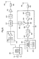
- the downlink transmitting interface 200 of the base station 100 will now be described in more detail, according to a preferred embodiment of the present invention, with reference to Figure 4 .
- the same reference numerals are used to label features shown in Figure 4 that are similar to those in any of the earlier figures.
- the base station 100 provides two communications channels. This two-channel example will be used as the basis for the remainder of the description in the present patent application in order to simplify the figures, although, of course, the base station 100 may be equipped to provide further data channels as required, as will become clear from the description that follows.
- components of a preferred two channel downlink transmitting interface 200 are shown.
- two modems (modulators) 205 are provided, one for each data channel.
- an appropriate one of the two data channels is selected and data is input to the respective modem 205 for that channel.
- the modem 205 modulates the input data signal, preferably according to the COFDM modulation scheme.
- the "I” and “Q” channel outputs from a (COFDM) modem 205 are converted into a combined first intermediate frequency channel by mixing each of the "I” and “Q” signals with a 520 MHz intermediate frequency (IF) oscillator signal, the "Q” signal being mixed with a 520 MHz IF oscillator signal that is a quarter cycle out of phase with that for the "I" signal, and combining the resultant signals.
- the combined signal from each modem 205 is passed through a 520MHz band-pass filter 405 having a bandwidth of approximately 340MHz, to remove any unwanted harmonics and noise that would typically be generated as a result of the preferred IF mixing and combining stage.
- the signal output from the filter 405 for each channel is then input to the downlink signal converter 210 for conversion into a signal of a predetermined frequency allocated for that data channel, preferably in the range 1.5 to 3.5GHz.
- the downlink signal converter 210 comprises, for each data channel, a mixer 410 and a local oscillator (LO) 415, 418.
- the frequencies of the local oscillators 415, 418 are selected to ensure that when the oscillator signal is mixed (410) with the output signal from the filter 405, a signal of the predetermined frequency for that channel is generated.
- the frequencies of the local oscillators 415, 418, and hence the predetermined frequencies for the channels are selected so as to minimise unwanted mixing products generated as a result of mixing the signal from the local oscillators 415, 418 with the output signals from the filters 405, bearing in mind the particular combination of frequencies used to generate those output signals.
- the local oscillator 415 for one of the channels is preferably set to a frequency of 1.43GHz and the local oscillator 418 for the other channel is set to a frequency of 2.68GHz.
- n modems 205, filters 405, mixers 410 and local oscillators 415, 418 would typically need to be provided, each local oscillator being set to a different frequency such as to generate a channel signal within a predetermined frequency range, e.g. 1.5-3.5GHz.
- the process of selecting channel frequencies and hence corresponding oscillator frequencies takes place as part of an overall design stage for the apparatus.
- a switching arrangement can be implemented to enable different local oscillators to be selected to enable switching between data channels and hence communication with different mobile terminal units 120, 125.
- tuneable local oscillators may be provided to achieve a similar effect.
- the output from the mixer 410 comprises not only a signal at the allocated frequency for the data channel but also signals at one or more other frequencies.
- a filter 420, 423 is used therefore to remove the unwanted components from the mixer output signal leaving only a signal of the allocated frequency for the data channel.
- the filters 420 and 423 are band-pass filters centred on frequencies of 1.95GHz and 3.2GHz respectively, both having a bandwidth greater than or equal to 340MHz.
- the signals emerging from the filters 420 and 423, each of a distinct frequency are combined in a combiner 425 to form a composite signal for input to the optical transmitter 215.
- the combiner 425 in the present example is a 2:1 combiner because there are only two data channels. If the base station 100 was equipped to provide n channels, then an n:1 combiner would be provided to combine the signals into a single composite channel.
- the optical transmitter 215 is constructed according to a cascaded optical modulator design.
- An optical carrier generated by a laser 430 is optically coupled using polarisation maintaining optical fibre to a first optical modulator 440 arranged to modulate the optical carrier with an amplified (437) and filtered (439) oscillator signal generated by an oscillator 435 to form an optical oscillator signal and, in a second optical modulator 445, optically coupled using polarisation maintaining optical fibre to the first optical modulator 440, the optical oscillator signal is modulated with an amplified (447) and filtered (449) composite signal output by the combiner 425.
- the frequency of the oscillator 435 is selected to ensure that a signal is output from the second optical modulator 445 having a predetermined frequency suitable for wireless transmission by the RAUs 110.
- This predetermined frequency would be required to fall within a range of frequencies for which a licence to transmit has been granted. In preferred embodiments of the present invention this range of frequencies is chosen to be 57-59GHz for the downlink and 62-64GHz for the uplink, with a local oscillator frequency of 60.5GHz.
- the downlink optical signal output by the second optical modulator 445 is split by the optical splitter 220 and injected into each of the downlink optical fibres 115 linking the base station 100 with the RAUs 110.
- the optical modulators 440 and 445 are preferably commercially available high frequency Mach-Zehnder (MZ) optical modulators.
- the first optical modulator 440 is biased at the minimum of its transfer characteristic so that a frequency-doubling effect can be achieved in modulating the laser light (430), preferably output by 50mW DFB laser diode 430, with the amplified oscillator signal (435, 437, 439).
- Frequency doubling may be achieved by biasing the first optical modulator 440 at either its maximum or minimum. However, it is preferable to bias at the minimum point as this minimises the dc light level at a photo-receiver and thus provides the best noise performance.
- a MZ modulator Making use of the frequency doubling properties of a MZ modulator enables an oscillator 435 having a frequency of only 30.25GHz to be used to generate a 60.5GHz oscillator signal in the optical output from the first MZ optical modulator 440 - in fact two optical oscillator sideband signals are generated, as shown (505) in Figure 5 , separated by 60.5GHz - the laser carrier itself (430) being suppressed.
- the second MZ optical modulator 445 is biased at the quadrature point, the most linear region of its transfer characteristic.
- each of the optical oscillator sidebands is modulated resulting in a pair of optical data signal sidebands centred about each of the optical oscillator sidebands, as shown (510) in Figure 5 , the first pair in the frequency range 57-59GHz and the second in the range 62-64GHz respectively in the present example, corresponding to the composite IF data signal frequency range of 1.5 to 3.5GHz.
- Each data signal sideband is separated, in the frequency domain, from the optical oscillator sideband signals according to the frequencies of the signal components within the composite IF data signal.
- the downlink optical signal output by the second MZ optical modulator 445 is then injected into each of the downlink optical fibres 115 for sending to the RAUs 110.
- the downlink optical signal output by the optical transmitter 215 at the base station 100 is received over the downlink optical fibre 115 at an optical interface 305 and passed to an optical receiver 310 comprising a photo-receiver 605.
- the RF electrical outputs from the photo-receiver 605 are the 60.5GHz local oscillator signal, as generated by the base station optical transmitter 215, and the lower and upper data signal sidebands in the frequency ranges 57-59GHz and 62-64GHz respectively (60.5GHz ⁇ 1.5-3.5GHz).
- the RF signals are amplified in an amplifier 610 and input to a diplexer 312 arranged to separate the local oscillator signal from the data signal sidebands.
- the lower frequency sideband in the range 57-59GHz is retained as the downlink signal for transmission by the RAU 1.10, while the upper frequency sideband is blocked by means of a band-pass filter 615 that permits only the lower frequency band to pass to the power amplifier 315 and then by means of an isolator 620 to the downlink antenna 320.
- the separated local oscillator signal is passed to the uplink signal converter 330 for use in converting received mm-wave uplink signals into IF uplink signals.
- a mm-wave signal transmitted by a mobile data terminal 120, 125 and received at the RAU 110 by the antenna 325 is passed by means of an isolator 635 to the uplink signal converter 330.
- the received uplink signal is first filtered in a band-pass filter 640 arranged to allow signals in the range 62-64GHz to pass - the preferred frequency range for uplink communications in the present example - then amplified in an amplifier 645 and input to a mixer 650.
- the separated 60.5GHz local oscillator signal from the diplexer 312 is filtered in a 60.5GHz band-pass filter and amplified by an amplifier 630 before input to the mixer 650.
- the result of mixing the 60.5GHz local oscillator signal with the received uplink signal is, amongst other mixing products, an uplink IF signal in the frequency range 1.5-3.5GHz.
- the mixer output is amplified in an amplifier 655 before filtering out all but the uplink IF signal in the frequency range 1.5-3.5GHz in a band-pass filter 660.
- the uplink signal converter 330 outputs the uplink IF signal to the uplink optical transmitter 335.
- the uplink optical transmitter 335 comprises an optical modulator 670 to modulate the uplink IF signal onto an optical carrier signal provided by a laser 675 to generate an uplink optical signal which is then injected into the uplink optical fibre 118 to the base station 100.
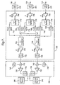
- the uplink receiving interface 245 of the base station 100 will now be described in more detail according to a preferred embodiment of the present invention with reference to Figure 7 .
- the same reference numerals are used to label features shown in Figure 7 that are similar to those in any of the earlier figures.
- the uplink receiving interface 245 in this example is arranged to interface with any combination of three RAUs 110, although of course the base station 100 may be scaled to interface with further RAUs 110 as will be clear from this description.
- Uplink optical signals received over any of the three uplink optical fibres 118 are detected by a photo-receiver 225 linked to that uplink optical fibre 118 by an appropriate interface.
- the photo-receiver 225 converts the received uplink optical signal into an uplink IF signal similar to that generated by the uplink signal converter 330 within the RAU 110.
- a different photo-receiver 225 is provided to receive signals from each of the three uplink optical fibres 118.
- the uplink IF signal output by each of the photo-receivers 225 is then input to the channel separator 230.
- Uplink optical signals received from an RAU 110 may carry signals for more than one data channel simultaneously if the RAU 110 was within range of multiple transmitting mobile terminal units 120, 125.
- the channel separator 230 is designed to separate the signals for each of the data channels and, where signals for a given data channel are separately received from more than one RAU 110, to combine all the received signals for a given data channel so as to output a combined channel signal for each channel.
- the three uplink optical fibre inputs 118 convert to two channel outputs from the channel separator 230.
- the signals for each data channel are distinguished by their differing frequencies.
- the channel separator 230 splits the uplink IF signal from each photo-receiver 225 along two signal paths, one signal path per data channel, using a splitter 710.
- one signal path leads to a 1.95GHz band-pass filter 715 to pass signals at the allocated frequency for the first data channel and the other signal path leads to a 3.2GHz band-pass filter 720 to pass signals at the allocated frequency for the second data channel.
- the uplink signal converter 235 comprises, for each data channel, a mixer 740, 742 and a local oscillator 745, 748.
- the local oscillators 745, 748 operate at the same frequencies as the local oscillators 415 and 418 respectively in the downlink transmitting interface 210 described above.
- the combined uplink IF signals for each channel are received at the respective mixer 740, 742 and mixed with the corresponding local oscillator signals.
- the resultant signals are then amplified by a respective IF amplifier 750, 752.
- the mixers 740, 742 generate a number of signal components of which only one is required. Therefore a band-pass filter 755, 758 is used to block the unwanted signal components for each channel before the required uplink signal components are output to be demodulated in respective COFDM demodulators 240.
- the modems 240 are COFDM modems.
- the demodulated data signal for each channel is then output from the modem 240, for example to the central terminal unit 105.
- a preferred mobile transmit/receive interface will now be described, with reference to Figure 8 , for use in a mobile terminal unit 120, 125 to enable communication with the base station 100 via the RAUs 110.
- the mobile transmit/receive interface may be physically mounted and electronically connected to a movable television camera to enable the camera to transmit image data to and receive control data from a central studio, for example, by means of the RAUs 110 and base station 100.
- components in a preferred mobile terminal unit 120, 125 are shown, including a data source 805, a TV camera for example, linked for uplink communications to the mobile transmit/receive interface 810 by means of a COFDM modulator 815.
- a downlink signal output from the mobile transmit/receive interface 810 is demodulated in a COFDM demodulator 820 for output (825) to a TV monitor, for example.
- Both the COFDM modulator 815 and demodulator 820 are arranged to cooperate with the demodulators 240 and modulators 205 respectively, as used in the base station 100.
- the COFDM modulator 815 includes circuitry to convert a baseband modulated signal into an IF uplink data signal of a predetermined frequency specific to that mobile transmit/receive interface 810, either 1.95GHz or 3.2GHz in the present two-channel example.
- the COFDM demodulator 820 includes circuitry to convert a downlink IF data signal into a signal of the required frequency for demodulation by the COFDM demodulator 820.
- the mobile transmit/receive interface is going to be used to communicate on only one of the data channels supported by the base station 100, although a switching arrangement can be provided at the mobile terminal unit 120, 125 if required to enable switching between channel frequencies in a similar manner to that mentioned above in describing the operation of a preferred base station 100.
- a signal input by the data source 805 is COFDM modulated and converted (815) into an IF uplink data signal.
- the mobile transmit/receive interface 810 receives the uplink IF data signal and amplifies it in an IF amplifier 830 and mixes the amplified signal in a mixer 835 with a 60.5GHz local oscillator signal, in the present example, generated by a local oscillator 840.
- the mixer output is then filtered in a band-pass fitter to block all but those mixer products in the preferred uplink wireless communication frequency range of 62-64GHz.
- the uplink data signal is transmitted wirelessly by means of an antenna 855 to be received by one or more RAUs 110.
- a signal transmitted by one or more RAUs 110 in the preferred downlink wireless communication frequency range of 57-59GHz for the present example, is received at an antenna 860.
- the received downlink signal is filtered in a 57-59GHz band-pass filter 865 and amplified in a low-noise amplifier (LNA) 870 before input to a mixer 875 arranged to mix the amplified signal with the local oscillator signal from oscillator 840.
- LNA low-noise amplifier
- One of the results of mixing the oscillator signal with a signal in the range 57-59GHz is a downlink IF data signal in the frequency range 1.5-3.5GHz.
- All other mixer products are blocked in a band-pass filter 880, leaving the downlink IF data signal to be amplified in an IF amplifier 885 for output from the mobile transmit/receive interface 810.
- the output IF data signal is converted and demodulated in the COFDM demodulator 820 and output (825), for example to a TV monitor.
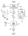
- each of the antennae are designed for use with signals in the frequency range 57 to 64GHz, although it would be apparent to a person of ordinary skill in the field of antenna design that the antennae may be designed to operate in other frequency ranges according to the particular application of the apparatus of the present invention.
- the preferred antenna 1000 is a rotationally symmetric shaped-dielectric lens antenna comprising a dielectric lens portion 1005, preferably made from PTFE, mounted on a conducting mounting plate 1010.
- the dielectric lens 1005 is of a known shape designed to produce a substantially sec 2 ⁇ radiation power pattern, where ⁇ is the angle measured from the axis of symmetry through the antenna 1000, for angles of ⁇ up to approximately 70°.
- This power pattern has been found to be suitable for use in an enclosed environment such as a television studio where the antenna is attached to the ceiling near to the centre of the space.
- This design forms a good compromise for use in such environments over an alternative known, but more complex, lens design capable of producing substantially rectangular radiation fields.
- FIG. 10b a plane section through the antenna 1000 is shown, taken through the plane indicated by the line A-A in Figure 10a .
- the shaped dielectric lens 1005 is attached to the conducting mounting plate 1010 by means of four fixing bolts 1015, each made, optionally, from a similar material to that used for the dielectric lens 1005 itself, although metal bolts may also be used.
- Each bolt 1015 engages with a corresponding threaded hole provided in a projecting annular portion 1016 of the dielectric lens 1005 which itself engages with a corresponding annular recess 1018 provided in the mounting plate 1010.
- a hole 1020 is provided through the centre of the mounting plate 1010 to provide a point of entry for a waveguide 1025 assembly.
- the waveguide assembly 1025 comprises an air-filled polariser, of conventional design, arranged in two parts to emit radiation with circular polarisation into the dielectric lens: a rectangular-sectioned portion 1030 leading to a flattened circular sectioned portion 1035, with appropriately shaped transition sections 1040 and 1045 disposed between the rectangular 1030 and flattened circular 1035 air-filled sections and between the air-filled flattened circular 1035 and dielectric-filled entry hole 1020, respectively.
- That portion of the hole 1020 not occupied by the waveguide feeder transition section 1045 is filled with dielectric material, preferably the same material as that used for the lens 1005 itself.
- a portion of the dielectric material may have a central bore or alternatively have its external radius reduced in order to provide an impedance matching section between the air-filled circular waveguide and dielectric-filled entry hole.
- an axially-symmetric pattern of circular grooves 1050 is cut into the surface of the dielectric lens to help to reduce the effects of internal reflections within the lens, in a known manner.
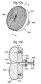
- a plan view of a preferred shaped radiation pattern antenna 1100 is shown for use with a mobile terminal unit 120, 125.
- the preferred antenna 1100 is a rotationally symmetric shaped-dielectric lens antenna comprising a dielectric lens portion 1105, also preferably made from PTFE, mounted on a conducting mounting plate 1110.
- the dielectric lens 1105 is shaped according to a known shape designed to produce a substantially hemispherical radiation power pattern.
- FIG. 11 b a plane section through the antenna 1100 is shown, taken through the plane indicated by the line B-B in Figure 11 a.
- the shaped dielectric lens 1105 is attached to the conducting mounting plate 1110 by means of a projecting annular portion 1115 which engages with a corresponding annular recess 1118 provided in the mounting plate 1110.
- a hole 1120 is provided through the centre of the mounting plate 1110 as a point of entry for a waveguide 1125 assembly.
- the waveguide assembly 1125 is similar in design to that (1025) used with the RAU antenna 1000 of Figure 10 , although with a smaller diameter feed 1130 into the dielectric lens 1105 to give a wider radiation pattern and hence a wider illumination of the lens 1105.
- the effect of internal reflections on the radiation pattern has been found to be greater than that with the RAU antenna 1000, in particular on the radiation pattern towards the outer limits of the field between 70° and 90° as measured from the axis of symmetry of the lens. It is has been found, however, that if an annular portion 1135 of a radiation absorbing material, for example Emerson & Cuming "Eccosorb AN-72"TM, is disposed in an annular recess formed towards the outer edge of the mounting plate 1110, a recess formed preferably by extending the width of the recess 1118 radially outwards, then the effect of the internal reflections can be considerably reduced.
- the projecting annular portion 1115 of dielectric material together with the annular portion of absorber material 1135 together fill the extended annular recess 1118 in the mounting plate 1110 to provide a secure attachment of the dielectric lens 1105 to the mount 1110.
- the surface of the dielectric lens 1105 of the mobile terminal unit antenna 1100 is provided with a pattern of circular grooves 1140 to reduce internal reflections.
- a single mobile terminal unit 120, 125 may require the entire bandwidth of a data channel
- a number of mobile terminal units may share a given data channel and the associated base station equipment by using a combination of Time Division Multiplexing (TDM) and Frequency Division Multiplexing (FDM). This would involve allocating time intervals to a group of mobile users who all operate at one frequency. There would be a number of these 'groups' operating at different frequencies.
- TDM Time Division Multiplexing
- FDM Frequency Division Multiplexing
Claims (12)
- Basisstation (100), betriebsfähig zum Kommunizieren von Daten über einen Zweiwege-Kommunikationskanal, hergestellt mit einer mobilen Endgeräteinheit (120, 125) durch mindestens eine Antenneneinheit (110), betriebsfähig zum drahtlosen Kommunizieren mit der mobilen Endgeräteinheit, wobei die Basisstation betriebsfähig ist, um mit der mindestens einen Antenneneinheit über eine Glasfaserverbindung (115, 118) zu kommunizieren, die Basisstation umfassend:einen optischen Sender (215) zum Erzeugen und Übertragen optischer Downlink-Datensignale zu der mindestens einen Antenneneinheit; undeinen optischen Empfänger (245) zum Empfangen von optischen Uplink-Datensignalen, erzeugt von der mindestens einen Antenneneinheit (110), in Bezug auf den Kommunikationskanal,wobei der optische Sender umfasst:eine Lichtquelle (430), betriebsfähig zum Erzeugen eines optischen Trägers und gekennzeichnet durch:einen ersten elekrooptischen Modulator (440), betriebsfähig zum Modulieren des optischen Trägers mit einem Hochfrequenzoszillatorsignal (435) zum Erzeugen eines optischen Oszillatorsignals mit einer Frequenz, die geeignet ist zur Verwendung durch die mindestens eine Antenneneinheit (110) beim Erzeugen von optischen Uplink-Datensignalen; undeinen zweiten elektrooptischen Modulator (445), optisch an den ersten elektrooptischen Modulator (440) gekoppelt und betriebsfähig zum Empfangen des optischen Oszillatorsignals und Modulieren dieses mit einem Eingangsdatensignal einer in Bezug auf den Kommunikationskanal zugeteilten Frequenz, um dadurch ein optisches Downlink-Datensignal, das das modulierte optische Oszillatorsignal umfasst, zu erzeugen und auszugeben.
- Basisstation nach Anspruch 1, wobei jeder des ersten und zweiten elektrooptischen Modulators (440, 445) ein optischer Mach-Zehnder-Modulator ist.
- Basisstation nach Anspruch 2, wobei der erste optische Mach-Zehnder-Modulator (440) bei dem Minimum seiner Übertragungscharakteristik vorgespannt ist, so dass das optische Oszillatorsignal ein Oszillatorsignal mit der zweifachen Frequenz des zum Modulieren des optischen Trägers verwendeten Hochfrequenzoszillatorsignals enthält.
- Basisstation nach Anspruch 2 oder Anspruch 3, wobei der zweite optische Mach-Zehnder-Modulator (445) bei dem Quadraturpunkt seiner Übertragungscharakteristik vorgespannt ist.
- Basisstation nach einem der vorstehenden Ansprüche, wobei der optische Empfänger (245) Fotoempfangsmittel (225) zum Detektieren von optischen Uplink-Datensignalen, empfangen über die Glasfaserverbindung (118) von der mindestens einen Antenneneinheit (110), und zum Trennen von Signalen in Bezug auf den Kommunikationskanal von denjenigen anderer Kanäle umfasst.
- Kommunikationssystem, umfassend eine Basisstation nach einem der vorstehenden Ansprüche.
- System nach Anspruch 6, enthaltend eine Antenneneinheit, umfassend:einen Fotodetektor (310) zum Umwandeln eines empfangenen optischen Downlink-Datensignals in ein Hochfrequenzsignal; undMittel (312) zum Trennen des Hochfrequenzsignals in ein Datensignal für drahtlose Übertragung durch die Antenneneinheit und ein lokales Oszillatorsignal zur Verwendung innerhalb der Antenneneinheit zum Erzeugen von optischen Uplink-Datensignalen.
- System nach Anspruch 7, wobei die Antenneneinheit weiter umfasst:einen Empfänger zum Empfangen eines von einer mobilen Endgeräteinheit übertragenen Hochfrequenzdatensignals;einen Umwandler (330) zum Umwandeln des empfangenen Hochfrequenzdatensignals unter Verwendung des lokalen Oszillatorsignals in ein Zwischenfrequenzdatensignal; undeinen optischen Sender (335) zum Erzeugen eines optischen Uplink-Datensignals zum Befördern des Zwischenfrequenzdatensignals zu der Basisstation (100).
- System nach einem der Ansprüche 6 bis 8, umfassend eine mobile Endgeräteinheit, aufweisend:einen Modulator (815), betriebsfähig zum Modulieren eines eingegebenen Datensignals;Signalumwandlungsmittel (835) zum Umwandeln des modulierten eingegebenen Datensignals in ein Uplink-Datensignal mit einer Frequenz innerhalb eines im Voraus bestimmten Frequenzbereichs, zugeteilt in Bezug auf einen Kommunikationskanal; undeinen Sender (850), betriebsfähig zum drahtlosen Übertragen des Uplink-Datensignals für Empfang durch mindestens eine mit der Basisstation verbundene Antenneneinheit.
- System nach Anspruch 9, wobei die Signalumwandlungsmittel umfassen:einen lokalen Oszillator (840), betriebsfähig bei einer Frequenz korrespondierend mit der eines Oszillatorsignals, ausgegeben von der Basisstation in einem optischen Downlink-Datensignal; undeinen Mischer (835), betriebsfähig zum Mischen eines von dem lokalen Oszillator ausgegebenen Oszillatorsignals mit dem von dem Modulator ausgegebenen modulierten Datensignal, um das Uplink-Datensignal zu erzeugen.
- Verfahren zum Kommunizieren von Daten über einen Zweiwege-Kommunikationskanal, hergestellt zwischen einer Basisstation (100) und einer mobilen Endgeräteinheit (120, 125) durch mindestens eine Antenneneinheit (110), die mittels einer Glasfaserverbindung (115, 118) mit der Basisstation (100) verbunden ist und betriebsfähig ist, um mit der mobilen Endgeräteinheit drahtlos zu kommunizieren, das Verfahren die folgenden Schritte umfassend:(i) an einem ersten elektrooptischen Modulator (440) innerhalb der Basisstation, Modulieren eines optischen Trägers mit dem Ausgang von einem Hochfrequenzoszillator (435) zum Erzeugen eines optischen Oszillatorsignals mit einer Frequenz, die geeignet ist zur Verwendung durch die mindestens eine Antenneneinheit (110) zum Erzeugen von optischen Uplink-Datensignalen;(ii) Empfangen des optischen Oszillatorsignals an einem zweiten elektrooptischen Modulator (445) innerhalb der Basisstation, optisch verbunden mit dem ersten elektrooptischen Modulator (440), Modulieren des optischen Oszillatorsignals mit einem eingegebenen modulierten Datensignal einer in Bezug auf den Kommunikationskanal zugeteilten Frequenz, um ein optisches Downlink-Datensignal zu erzeugen;(iii) Befördern des optischen Downlink-Datensignals mittels der Glasfaserverbindung (115) zu der mindestens einen Antenneneinheit (110); und(iv) an der mindestens einen Antenneneinheit (110), Umwandeln des optischen Downlink-Datensignals in ein Hochfrequenzdatensignal für drahtlose Übertragung und ein lokales Oszillatorsignal zur Verwendung innerhalb der Antenneneinheit zum Erzeugen von optischen Uplink-Datensignalen.
- Verfahren nach Anspruch 11, weiter die folgenden Schritte umfassend:(v) Empfangen, an der mindestens einen Antenneneinheit (110), eines von der mobilen Endgeräteinheit (120, 125) über den Kommunikationskanal übertragenen modulierten Datensignals und, unter Verwendung des lokalen Oszillatorsignals aus Schritt (iv), Umwandeln des empfangenen modulierten Datensignals in ein Zwischenfrequenzdatensignal; und(vi) Übertragen des Zwischenfrequenzdatensignals als ein optisches Uplink-Datensignal zu der Basisstation über die Glasfaserverbindung (118).
Priority Applications (1)
| Application Number | Priority Date | Filing Date | Title |
|---|---|---|---|
| EP05798421A EP1815618B1 (de) | 2004-11-15 | 2005-10-27 | Datenkommunikationssystem |
Applications Claiming Priority (4)
| Application Number | Priority Date | Filing Date | Title |
|---|---|---|---|
| GB0425156A GB0425156D0 (en) | 2004-11-15 | 2004-11-15 | Data communications |
| EP04257067 | 2004-11-15 | ||
| EP05798421A EP1815618B1 (de) | 2004-11-15 | 2005-10-27 | Datenkommunikationssystem |
| PCT/GB2005/004152 WO2006051262A1 (en) | 2004-11-15 | 2005-10-27 | Data communications system |
Publications (2)
| Publication Number | Publication Date |
|---|---|
| EP1815618A1 EP1815618A1 (de) | 2007-08-08 |
| EP1815618B1 true EP1815618B1 (de) | 2012-09-12 |
Family
ID=35519885
Family Applications (1)
| Application Number | Title | Priority Date | Filing Date |
|---|---|---|---|
| EP05798421A Active EP1815618B1 (de) | 2004-11-15 | 2005-10-27 | Datenkommunikationssystem |
Country Status (6)
| Country | Link |
|---|---|
| US (1) | US8055136B2 (de) |
| EP (1) | EP1815618B1 (de) |
| JP (1) | JP4723575B2 (de) |
| AU (1) | AU2005303660B2 (de) |
| ES (1) | ES2395036T3 (de) |
| WO (1) | WO2006051262A1 (de) |
Families Citing this family (78)
| Publication number | Priority date | Publication date | Assignee | Title |
|---|---|---|---|---|
| US20070248358A1 (en) * | 2006-04-19 | 2007-10-25 | Michael Sauer | Electrical-optical cable for wireless systems |
| US20070286599A1 (en) * | 2006-06-12 | 2007-12-13 | Michael Sauer | Centralized optical-fiber-based wireless picocellular systems and methods |
| US7627250B2 (en) * | 2006-08-16 | 2009-12-01 | Corning Cable Systems Llc | Radio-over-fiber transponder with a dual-band patch antenna system |
| US7787823B2 (en) | 2006-09-15 | 2010-08-31 | Corning Cable Systems Llc | Radio-over-fiber (RoF) optical fiber cable system with transponder diversity and RoF wireless picocellular system using same |
| US7848654B2 (en) | 2006-09-28 | 2010-12-07 | Corning Cable Systems Llc | Radio-over-fiber (RoF) wireless picocellular system with combined picocells |
| US8873585B2 (en) | 2006-12-19 | 2014-10-28 | Corning Optical Communications Wireless Ltd | Distributed antenna system for MIMO technologies |
| US8111998B2 (en) * | 2007-02-06 | 2012-02-07 | Corning Cable Systems Llc | Transponder systems and methods for radio-over-fiber (RoF) wireless picocellular systems |
| US20100054746A1 (en) | 2007-07-24 | 2010-03-04 | Eric Raymond Logan | Multi-port accumulator for radio-over-fiber (RoF) wireless picocellular systems |
| US8175459B2 (en) | 2007-10-12 | 2012-05-08 | Corning Cable Systems Llc | Hybrid wireless/wired RoF transponder and hybrid RoF communication system using same |
| WO2009053910A2 (en) | 2007-10-22 | 2009-04-30 | Mobileaccess Networks Ltd. | Communication system using low bandwidth wires |
| CN101459470A (zh) * | 2007-12-14 | 2009-06-17 | 华为技术有限公司 | 光传输系统、装置和方法 |
| US8175649B2 (en) | 2008-06-20 | 2012-05-08 | Corning Mobileaccess Ltd | Method and system for real time control of an active antenna over a distributed antenna system |
| WO2009081376A2 (en) | 2007-12-20 | 2009-07-02 | Mobileaccess Networks Ltd. | Extending outdoor location based services and applications into enclosed areas |
| US8532498B2 (en) * | 2008-02-08 | 2013-09-10 | Celight | Secure orthogonal frequency multiplexed optical communications |
| US20090290877A1 (en) * | 2008-05-21 | 2009-11-26 | Nec Laboratories America, Inc. | Monitoring for High Speed OFDM Signal Transmission |
| US20090290878A1 (en) * | 2008-05-22 | 2009-11-26 | Nec Laboratories America, Inc. | Generating an Optical OFDM Signal with Reduced OSNR Requirement |
| CN102209921B (zh) | 2008-10-09 | 2015-11-25 | 康宁光缆系统有限公司 | 具有支持来自光学分路器的输入和输出光纤的适配器面板的光纤终端 |
| CN102396171B (zh) | 2009-02-03 | 2015-09-30 | 康宁光缆系统有限责任公司 | 基于光纤的分布式天线系统、组件和用于监视和配置基于光纤的分布式天线系统、组件的相关方法 |
| US9673904B2 (en) | 2009-02-03 | 2017-06-06 | Corning Optical Communications LLC | Optical fiber-based distributed antenna systems, components, and related methods for calibration thereof |
| WO2010091004A1 (en) | 2009-02-03 | 2010-08-12 | Corning Cable Systems Llc | Optical fiber-based distributed antenna systems, components, and related methods for calibration thereof |
| CN102232191B (zh) | 2009-02-08 | 2015-07-08 | 康宁移动接入有限公司 | 采用携带以太网信号的电缆的通信系统 |
| US8498539B1 (en) * | 2009-04-21 | 2013-07-30 | Oewaves, Inc. | Dielectric photonic receivers and concentrators for radio frequency and microwave applications |
| US8548330B2 (en) | 2009-07-31 | 2013-10-01 | Corning Cable Systems Llc | Sectorization in distributed antenna systems, and related components and methods |
| US8280259B2 (en) | 2009-11-13 | 2012-10-02 | Corning Cable Systems Llc | Radio-over-fiber (RoF) system for protocol-independent wired and/or wireless communication |
| US8275265B2 (en) | 2010-02-15 | 2012-09-25 | Corning Cable Systems Llc | Dynamic cell bonding (DCB) for radio-over-fiber (RoF)-based networks and communication systems and related methods |
| US9525488B2 (en) | 2010-05-02 | 2016-12-20 | Corning Optical Communications LLC | Digital data services and/or power distribution in optical fiber-based distributed communications systems providing digital data and radio frequency (RF) communications services, and related components and methods |
| US20110268446A1 (en) | 2010-05-02 | 2011-11-03 | Cune William P | Providing digital data services in optical fiber-based distributed radio frequency (rf) communications systems, and related components and methods |
| WO2012024247A1 (en) * | 2010-08-16 | 2012-02-23 | Corning Cable Systems Llc | Remote antenna clusters and related systems, components, and methods supporting digital data signal propagation between remote antenna units |
| US9252874B2 (en) | 2010-10-13 | 2016-02-02 | Ccs Technology, Inc | Power management for remote antenna units in distributed antenna systems |
| US9547145B2 (en) | 2010-10-19 | 2017-01-17 | Corning Optical Communications LLC | Local convergence point for multiple dwelling unit fiber optic distribution network |
| EP2678972B1 (de) | 2011-02-21 | 2018-09-05 | Corning Optical Communications LLC | Bereitstellung digitaler datendienste als elektrische signale und hochfrequenz (hf)-kommunikationen über glasfasern in verteilten kommunikationssystemen sowie entsprechende komponenten und verfahren |
| US8483566B2 (en) * | 2011-03-10 | 2013-07-09 | Titan Photonics, Inc. | Sub-octave RF stacking for optical transport and de-stacking for distribution |
| EP2702710A4 (de) | 2011-04-29 | 2014-10-29 | Corning Cable Sys Llc | Bestimmung der weiterleitungsverzögerung von kommunikationen in verteilten antennensystemen sowie entsprechende komponenten, systeme und verfahren |
| EP2702780A4 (de) | 2011-04-29 | 2014-11-12 | Corning Cable Sys Llc | Systeme, verfahren und vorrichtungen zur erhöhung einer hochfrequenz (hf)-leistung in verteilten antennensystemen |
| US9219546B2 (en) * | 2011-12-12 | 2015-12-22 | Corning Optical Communications LLC | Extremely high frequency (EHF) distributed antenna systems, and related components and methods |
| US9128124B2 (en) * | 2012-02-10 | 2015-09-08 | California Institute Of Technology | Wireless voltage sensing device |
| US10110307B2 (en) | 2012-03-02 | 2018-10-23 | Corning Optical Communications LLC | Optical network units (ONUs) for high bandwidth connectivity, and related components and methods |
| EP2829152A2 (de) | 2012-03-23 | 2015-01-28 | Corning Optical Communications Wireless Ltd. | Rfic-chip(s) zur bereitstellung von funktionalitäten eines verteilten antennensystems sowie entsprechende komponenten, systeme und verfahren |
| EP2832012A1 (de) | 2012-03-30 | 2015-02-04 | Corning Optical Communications LLC | Reduzierung ortsabhängiger interferenzen in verteilten antennensystemen in einer mimo-konfiguration sowie entsprechende komponenten, systeme und verfahren |
| WO2013162988A1 (en) | 2012-04-25 | 2013-10-31 | Corning Cable Systems Llc | Distributed antenna system architectures |
| EP2883416A1 (de) | 2012-08-07 | 2015-06-17 | Corning Optical Communications Wireless Ltd. | Verteilung von zeitlich gemultiplexten (tdm) management-diensten in einem verteilten antennensystem sowie entsprechende komponenten, systeme und verfahren |
| US8909057B2 (en) * | 2012-08-14 | 2014-12-09 | Titan Photonics | System using frequency conversions for sub-octave transmission of signals over a fiber optic |
| US9455784B2 (en) | 2012-10-31 | 2016-09-27 | Corning Optical Communications Wireless Ltd | Deployable wireless infrastructures and methods of deploying wireless infrastructures |
| CN105308876B (zh) | 2012-11-29 | 2018-06-22 | 康宁光电通信有限责任公司 | 分布式天线系统中的远程单元天线结合 |
| US9647758B2 (en) | 2012-11-30 | 2017-05-09 | Corning Optical Communications Wireless Ltd | Cabling connectivity monitoring and verification |
| GB2510885B (en) * | 2013-02-18 | 2020-02-19 | Bae Systems Plc | Integrated lighting and network interface device |
| EP3008828B1 (de) | 2013-06-12 | 2017-08-09 | Corning Optical Communications Wireless Ltd. | Zeitduplexierung (tdd) in verteilten kommunikationssystemen, einschliesslich verteilten antennensystemen (dass) |
| CN105452951B (zh) | 2013-06-12 | 2018-10-19 | 康宁光电通信无线公司 | 电压控制式光学定向耦合器 |
| US9247543B2 (en) | 2013-07-23 | 2016-01-26 | Corning Optical Communications Wireless Ltd | Monitoring non-supported wireless spectrum within coverage areas of distributed antenna systems (DASs) |
| US9661781B2 (en) | 2013-07-31 | 2017-05-23 | Corning Optical Communications Wireless Ltd | Remote units for distributed communication systems and related installation methods and apparatuses |
| US9385810B2 (en) | 2013-09-30 | 2016-07-05 | Corning Optical Communications Wireless Ltd | Connection mapping in distributed communication systems |
| US9178635B2 (en) | 2014-01-03 | 2015-11-03 | Corning Optical Communications Wireless Ltd | Separation of communication signal sub-bands in distributed antenna systems (DASs) to reduce interference |
| US9775123B2 (en) | 2014-03-28 | 2017-09-26 | Corning Optical Communications Wireless Ltd. | Individualized gain control of uplink paths in remote units in a distributed antenna system (DAS) based on individual remote unit contribution to combined uplink power |
| US9357551B2 (en) | 2014-05-30 | 2016-05-31 | Corning Optical Communications Wireless Ltd | Systems and methods for simultaneous sampling of serial digital data streams from multiple analog-to-digital converters (ADCS), including in distributed antenna systems |
| US9525472B2 (en) | 2014-07-30 | 2016-12-20 | Corning Incorporated | Reducing location-dependent destructive interference in distributed antenna systems (DASS) operating in multiple-input, multiple-output (MIMO) configuration, and related components, systems, and methods |
| WO2016030880A2 (en) | 2014-08-25 | 2016-03-03 | Corning Optical Communications Wireless Ltd. | Supporting an add-on remote unit (ru) in an optical fiber-based distributed antenna system (das) over an existing optical fiber communications medium using radio frequency (rf) multiplexing |
| US9730228B2 (en) | 2014-08-29 | 2017-08-08 | Corning Optical Communications Wireless Ltd | Individualized gain control of remote uplink band paths in a remote unit in a distributed antenna system (DAS), based on combined uplink power level in the remote unit |
| US9602210B2 (en) | 2014-09-24 | 2017-03-21 | Corning Optical Communications Wireless Ltd | Flexible head-end chassis supporting automatic identification and interconnection of radio interface modules and optical interface modules in an optical fiber-based distributed antenna system (DAS) |
| US9184960B1 (en) | 2014-09-25 | 2015-11-10 | Corning Optical Communications Wireless Ltd | Frequency shifting a communications signal(s) in a multi-frequency distributed antenna system (DAS) to avoid or reduce frequency interference |
| US9420542B2 (en) | 2014-09-25 | 2016-08-16 | Corning Optical Communications Wireless Ltd | System-wide uplink band gain control in a distributed antenna system (DAS), based on per band gain control of remote uplink paths in remote units |
| US10659163B2 (en) | 2014-09-25 | 2020-05-19 | Corning Optical Communications LLC | Supporting analog remote antenna units (RAUs) in digital distributed antenna systems (DASs) using analog RAU digital adaptors |
| WO2016071902A1 (en) | 2014-11-03 | 2016-05-12 | Corning Optical Communications Wireless Ltd. | Multi-band monopole planar antennas configured to facilitate improved radio frequency (rf) isolation in multiple-input multiple-output (mimo) antenna arrangement |
| WO2016075696A1 (en) | 2014-11-13 | 2016-05-19 | Corning Optical Communications Wireless Ltd. | Analog distributed antenna systems (dass) supporting distribution of digital communications signals interfaced from a digital signal source and analog radio frequency (rf) communications signals |
| US9866928B2 (en) * | 2014-11-21 | 2018-01-09 | Nec Corporation | Intra-transceiver optical superchannel switching via RF sub-band multiplexing technique |
| US9729267B2 (en) | 2014-12-11 | 2017-08-08 | Corning Optical Communications Wireless Ltd | Multiplexing two separate optical links with the same wavelength using asymmetric combining and splitting |
| EP3235336A1 (de) | 2014-12-18 | 2017-10-25 | Corning Optical Communications Wireless Ltd. | Digitale schnittstellenmodule (dim) zur flexiblen verteilung digitaler und/oder analoger kommunikationssignale in wad-antennensystemen |
| WO2016098111A1 (en) | 2014-12-18 | 2016-06-23 | Corning Optical Communications Wireless Ltd. | Digital- analog interface modules (da!ms) for flexibly.distributing digital and/or analog communications signals in wide-area analog distributed antenna systems (dass) |
| US20160249365A1 (en) | 2015-02-19 | 2016-08-25 | Corning Optical Communications Wireless Ltd. | Offsetting unwanted downlink interference signals in an uplink path in a distributed antenna system (das) |
| US9787400B2 (en) * | 2015-04-08 | 2017-10-10 | Corning Optical Communications LLC | Fiber-wireless system and methods for simplified and flexible FTTX deployment and installation |
| US9681313B2 (en) | 2015-04-15 | 2017-06-13 | Corning Optical Communications Wireless Ltd | Optimizing remote antenna unit performance using an alternative data channel |
| US9948349B2 (en) | 2015-07-17 | 2018-04-17 | Corning Optical Communications Wireless Ltd | IOT automation and data collection system |
| US10560214B2 (en) | 2015-09-28 | 2020-02-11 | Corning Optical Communications LLC | Downlink and uplink communication path switching in a time-division duplex (TDD) distributed antenna system (DAS) |
| US10236924B2 (en) | 2016-03-31 | 2019-03-19 | Corning Optical Communications Wireless Ltd | Reducing out-of-channel noise in a wireless distribution system (WDS) |
| US10735838B2 (en) | 2016-11-14 | 2020-08-04 | Corning Optical Communications LLC | Transparent wireless bridges for optical fiber-wireless networks and related methods and systems |
| GB202104000D0 (en) * | 2021-03-23 | 2021-05-05 | British Telecomm | Improvements to network synchronisation |
| KR102585785B1 (ko) * | 2021-05-31 | 2023-10-13 | 한국기계연구원 | 절대거리 측정 기반 다변측정시스템 및 이를 이용한 다변측정방법 |
| CN115015953B (zh) * | 2022-06-06 | 2023-02-28 | 长沙思木锐信息技术有限公司 | 微波驱动的fmcw激光雷达探测装置及其探测方法 |
| CN115276803B (zh) * | 2022-08-01 | 2023-10-13 | 南京航空航天大学 | 一种全双工光载无线通信方法及系统 |
Citations (1)
| Publication number | Priority date | Publication date | Assignee | Title |
|---|---|---|---|---|
| EP1357683B1 (de) * | 2002-04-25 | 2009-05-13 | Samsung Electronics Co., Ltd. | Hybrides Faser-Funksystem |
Family Cites Families (25)
| Publication number | Priority date | Publication date | Assignee | Title |
|---|---|---|---|---|
| CA2008900C (en) | 1989-04-04 | 1998-01-20 | Ta-Shing Chu | Optical fiber microcellular mobile radio |
| US5029003A (en) * | 1989-12-18 | 1991-07-02 | General Electric Company | Apparatus for incorporating digital signals with a standard TV signal |
| JPH0556176A (ja) * | 1991-08-27 | 1993-03-05 | Aiphone Co Ltd | 拡声式無線インターホン装置 |
| JP2641383B2 (ja) * | 1993-08-09 | 1997-08-13 | 株式会社エイ・ティ・アール光電波通信研究所 | Bpsk光送信装置及び光ファイバリンクシステム |
| EP0865690B1 (de) * | 1995-12-07 | 2003-02-26 | Vistar Telecommunications Inc. | Drahtloses verteiltes datenpaketübertragungssystem |
| JP2000506689A (ja) * | 1995-12-29 | 2000-05-30 | エリクソン インコーポレイテッド | 時間圧縮トランスポンダ |
| AU717824B2 (en) * | 1996-07-19 | 2000-04-06 | Nextg Networks, Inc. | Telecommunications system simultaneously receiving and modulating an optical signal |
| US5936754A (en) * | 1996-12-02 | 1999-08-10 | At&T Corp. | Transmission of CDMA signals over an analog optical link |
| KR100257184B1 (ko) | 1998-01-31 | 2000-05-15 | 정장호 | 서비스범위 확장을 위한 광중계 시스템 |
| JPH11355209A (ja) * | 1998-06-11 | 1999-12-24 | Toshiba Corp | 光アナログ伝送装置 |
| JP3974273B2 (ja) * | 1998-10-30 | 2007-09-12 | 株式会社東芝 | 通信システム |
| JP2000310800A (ja) * | 1999-02-23 | 2000-11-07 | Atr Adaptive Communications Res Lab | 2光信号発生器 |
| US6650630B1 (en) * | 1999-06-25 | 2003-11-18 | Telefonaktiebolaget Lm Ericsson (Publ) | Resource management and traffic control in time-division-duplex communication systems |
| JP2001044942A (ja) * | 1999-08-02 | 2001-02-16 | Matsushita Electric Ind Co Ltd | 光伝送装置 |
| JP3297734B2 (ja) * | 1999-09-29 | 2002-07-02 | 独立行政法人通信総合研究所 | ミリ波無線双方向伝送方法およびミリ波無線双方向伝送装置 |
| JP3594862B2 (ja) * | 1999-12-28 | 2004-12-02 | 株式会社エヌ・ティ・ティ・ドコモ | 無線基地局システム、統括局及び該統括局における信号処理方法 |
| JP4624603B2 (ja) * | 2000-06-29 | 2011-02-02 | パナソニック株式会社 | 無線アクセス用光伝送システム及び高周波光送信器 |
| US20020012495A1 (en) * | 2000-06-29 | 2002-01-31 | Hiroyuki Sasai | Optical transmission system for radio access and high frequency optical transmitter |
| KR100338623B1 (ko) * | 2000-07-10 | 2002-05-30 | 윤종용 | 디지털 광 링크를 이용한 이동통신망 시스템 |
| US20020114047A1 (en) * | 2000-11-22 | 2002-08-22 | Jds Uniphase Corporation | Cascaded RZ and NRZ laser modulators having RZ/NRZ phase alignment bias control |
| US6917455B2 (en) * | 2000-11-22 | 2005-07-12 | Jds Uniphase Corporation | Cascaded RZ and NRZ laser modulators having RZ/NRZ phase alignment bias control |
| GB2370170B (en) | 2000-12-15 | 2003-01-29 | Ntl Group Ltd | Signal transmission systems |
| US6671079B2 (en) * | 2001-12-14 | 2003-12-30 | Lucent Technologies Inc. | Method and apparatus for transmitting a modulated optical signal |
| JP2003324393A (ja) * | 2002-02-26 | 2003-11-14 | Matsushita Electric Ind Co Ltd | 双方向光伝送システム並びにそれに用いられる親局及び子局 |
| EP1443687B1 (de) * | 2003-01-29 | 2008-04-09 | Siemens S.p.A. | Verbesserte VCSEL analoge optische Verbindung |
-
2005
- 2005-10-27 ES ES05798421T patent/ES2395036T3/es active Active
- 2005-10-27 US US11/665,261 patent/US8055136B2/en not_active Expired - Fee Related
- 2005-10-27 WO PCT/GB2005/004152 patent/WO2006051262A1/en active Application Filing
- 2005-10-27 AU AU2005303660A patent/AU2005303660B2/en not_active Ceased
- 2005-10-27 EP EP05798421A patent/EP1815618B1/de active Active
- 2005-10-27 JP JP2007516054A patent/JP4723575B2/ja not_active Expired - Fee Related
Patent Citations (1)
| Publication number | Priority date | Publication date | Assignee | Title |
|---|---|---|---|---|
| EP1357683B1 (de) * | 2002-04-25 | 2009-05-13 | Samsung Electronics Co., Ltd. | Hybrides Faser-Funksystem |
Also Published As
| Publication number | Publication date |
|---|---|
| ES2395036T3 (es) | 2013-02-07 |
| AU2005303660B2 (en) | 2011-04-28 |
| US20090047023A1 (en) | 2009-02-19 |
| US8055136B2 (en) | 2011-11-08 |
| JP2008507862A (ja) | 2008-03-13 |
| AU2005303660A1 (en) | 2006-05-18 |
| WO2006051262A1 (en) | 2006-05-18 |
| EP1815618A1 (de) | 2007-08-08 |
| JP4723575B2 (ja) | 2011-07-13 |
Similar Documents
| Publication | Publication Date | Title |
|---|---|---|
| EP1815618B1 (de) | Datenkommunikationssystem | |
| EP1825700B1 (de) | Datenkommunikationsvorrichtung mit mehreren antennen | |
| US9461719B2 (en) | Distributed antenna system for MIMO technologies | |
| KR19980064467A (ko) | 서브섹터된 업스트림 안테나를 갖는지점 대 다지점간 통신 시스템 | |
| KR19980064516A (ko) | 원격 다지점 국을 제어하기 위한 방법 및 시스템 | |
| JP2005503709A (ja) | 自由空間ミリ波中継線によるセルラー電話システム | |
| CA2475849A1 (en) | Radio communication method and system for communication between a plurality of radio communication terminals | |
| US7251461B2 (en) | Wireless communications system, wireless transmitter, and wireless receiver | |
| US10819436B2 (en) | Base station apparatus, ground station device, and ground antenna device | |
| US10170832B2 (en) | Transceiver for a phased array antenna | |
| Ruggeri et al. | Multi-user IFoF uplink transmission over a 32-element 60GHz phased array antenna enabling both frequency and spatial division multiplexing | |
| Choi et al. | Millimeter-wave fiber-fed wireless access systems based on dense wavelength-division-multiplexing networks | |
| EP1657786A1 (de) | Linsenantenne | |
| JP2007043476A (ja) | 無線送信装置および無線送受信システム | |
| Dat et al. | Low-latency fiber-millimeter-wave system for future mobile fronthauling | |
| CN117176255A (zh) | 一种面向5g前传的光载模拟多样射频无线传输方法 | |
| Avramopoulosd et al. | An end-to-end 5G fiber wireless A-RoF/IFoF link based on a 60 GHz beamsteering antenna and an InP EML | |
| WO1994006205A1 (en) | Transmission via a common communication link of both a downconverted modulated radio frequency signal and a pilot signal used for conversion | |
| KR20000051464A (ko) | 다중섹터 방식의 마이크로셀룰라 시스템에서의 다중대역 다중반송파 전송장치 | |
| CZ284987B6 (cs) | Distribuční systém videosignálů |
Legal Events
| Date | Code | Title | Description |
|---|---|---|---|
| PUAI | Public reference made under article 153(3) epc to a published international application that has entered the european phase |
Free format text: ORIGINAL CODE: 0009012 |
|
| 17P | Request for examination filed |
Effective date: 20070606 |
|
| AK | Designated contracting states |
Kind code of ref document: A1 Designated state(s): AT BE BG CH CY CZ DE DK EE ES FI FR GB GR HU IE IS IT LI LT LU LV MC NL PL PT RO SE SI SK TR |
|
| DAX | Request for extension of the european patent (deleted) | ||
| 17Q | First examination report despatched |
Effective date: 20080904 |
|
| GRAP | Despatch of communication of intention to grant a patent |
Free format text: ORIGINAL CODE: EPIDOSNIGR1 |
|
| GRAS | Grant fee paid |
Free format text: ORIGINAL CODE: EPIDOSNIGR3 |
|
| GRAA | (expected) grant |
Free format text: ORIGINAL CODE: 0009210 |
|
| AK | Designated contracting states |
Kind code of ref document: B1 Designated state(s): AT BE BG CH CY CZ DE DK EE ES FI FR GB GR HU IE IS IT LI LT LU LV MC NL PL PT RO SE SI SK TR |
|
| REG | Reference to a national code |
Ref country code: GB Ref legal event code: FG4D |
|
| REG | Reference to a national code |
Ref country code: CH Ref legal event code: EP |
|
| REG | Reference to a national code |
Ref country code: AT Ref legal event code: REF Ref document number: 575448 Country of ref document: AT Kind code of ref document: T Effective date: 20120915 |
|
| REG | Reference to a national code |
Ref country code: DE Ref legal event code: R082 Ref document number: 602005036125 Country of ref document: DE Representative=s name: KILBURN & STRODE LLP, GB |
|
| REG | Reference to a national code |
Ref country code: IE Ref legal event code: FG4D |
|
| REG | Reference to a national code |
Ref country code: DE Ref legal event code: R096 Ref document number: 602005036125 Country of ref document: DE Effective date: 20121108 |
|
| REG | Reference to a national code |
Ref country code: SE Ref legal event code: TRGR |
|
| REG | Reference to a national code |
Ref country code: NL Ref legal event code: T3 |
|
| PG25 | Lapsed in a contracting state [announced via postgrant information from national office to epo] |
Ref country code: CY Free format text: LAPSE BECAUSE OF FAILURE TO SUBMIT A TRANSLATION OF THE DESCRIPTION OR TO PAY THE FEE WITHIN THE PRESCRIBED TIME-LIMIT Effective date: 20120912 Ref country code: LT Free format text: LAPSE BECAUSE OF FAILURE TO SUBMIT A TRANSLATION OF THE DESCRIPTION OR TO PAY THE FEE WITHIN THE PRESCRIBED TIME-LIMIT Effective date: 20120912 Ref country code: FI Free format text: LAPSE BECAUSE OF FAILURE TO SUBMIT A TRANSLATION OF THE DESCRIPTION OR TO PAY THE FEE WITHIN THE PRESCRIBED TIME-LIMIT Effective date: 20120912 |
|
| REG | Reference to a national code |
Ref country code: ES Ref legal event code: FG2A Ref document number: 2395036 Country of ref document: ES Kind code of ref document: T3 Effective date: 20130207 |
|
| REG | Reference to a national code |
Ref country code: AT Ref legal event code: MK05 Ref document number: 575448 Country of ref document: AT Kind code of ref document: T Effective date: 20120912 |
|
| REG | Reference to a national code |
Ref country code: LT Ref legal event code: MG4D Effective date: 20120912 |
|
| PG25 | Lapsed in a contracting state [announced via postgrant information from national office to epo] |
Ref country code: LV Free format text: LAPSE BECAUSE OF FAILURE TO SUBMIT A TRANSLATION OF THE DESCRIPTION OR TO PAY THE FEE WITHIN THE PRESCRIBED TIME-LIMIT Effective date: 20120912 Ref country code: GR Free format text: LAPSE BECAUSE OF FAILURE TO SUBMIT A TRANSLATION OF THE DESCRIPTION OR TO PAY THE FEE WITHIN THE PRESCRIBED TIME-LIMIT Effective date: 20121213 Ref country code: SI Free format text: LAPSE BECAUSE OF FAILURE TO SUBMIT A TRANSLATION OF THE DESCRIPTION OR TO PAY THE FEE WITHIN THE PRESCRIBED TIME-LIMIT Effective date: 20120912 |
|
| PG25 | Lapsed in a contracting state [announced via postgrant information from national office to epo] |
Ref country code: IS Free format text: LAPSE BECAUSE OF FAILURE TO SUBMIT A TRANSLATION OF THE DESCRIPTION OR TO PAY THE FEE WITHIN THE PRESCRIBED TIME-LIMIT Effective date: 20130112 Ref country code: RO Free format text: LAPSE BECAUSE OF FAILURE TO SUBMIT A TRANSLATION OF THE DESCRIPTION OR TO PAY THE FEE WITHIN THE PRESCRIBED TIME-LIMIT Effective date: 20120912 Ref country code: EE Free format text: LAPSE BECAUSE OF FAILURE TO SUBMIT A TRANSLATION OF THE DESCRIPTION OR TO PAY THE FEE WITHIN THE PRESCRIBED TIME-LIMIT Effective date: 20120912 Ref country code: BE Free format text: LAPSE BECAUSE OF FAILURE TO SUBMIT A TRANSLATION OF THE DESCRIPTION OR TO PAY THE FEE WITHIN THE PRESCRIBED TIME-LIMIT Effective date: 20120912 Ref country code: CZ Free format text: LAPSE BECAUSE OF FAILURE TO SUBMIT A TRANSLATION OF THE DESCRIPTION OR TO PAY THE FEE WITHIN THE PRESCRIBED TIME-LIMIT Effective date: 20120912 |
|
| PG25 | Lapsed in a contracting state [announced via postgrant information from national office to epo] |
Ref country code: MC Free format text: LAPSE BECAUSE OF NON-PAYMENT OF DUE FEES Effective date: 20121031 Ref country code: SK Free format text: LAPSE BECAUSE OF FAILURE TO SUBMIT A TRANSLATION OF THE DESCRIPTION OR TO PAY THE FEE WITHIN THE PRESCRIBED TIME-LIMIT Effective date: 20120912 Ref country code: PT Free format text: LAPSE BECAUSE OF FAILURE TO SUBMIT A TRANSLATION OF THE DESCRIPTION OR TO PAY THE FEE WITHIN THE PRESCRIBED TIME-LIMIT Effective date: 20130114 Ref country code: PL Free format text: LAPSE BECAUSE OF FAILURE TO SUBMIT A TRANSLATION OF THE DESCRIPTION OR TO PAY THE FEE WITHIN THE PRESCRIBED TIME-LIMIT Effective date: 20120912 |
|
| REG | Reference to a national code |
Ref country code: CH Ref legal event code: PL |
|
| PG25 | Lapsed in a contracting state [announced via postgrant information from national office to epo] |
Ref country code: AT Free format text: LAPSE BECAUSE OF FAILURE TO SUBMIT A TRANSLATION OF THE DESCRIPTION OR TO PAY THE FEE WITHIN THE PRESCRIBED TIME-LIMIT Effective date: 20120912 |
|
| PLBE | No opposition filed within time limit |
Free format text: ORIGINAL CODE: 0009261 |
|
| STAA | Information on the status of an ep patent application or granted ep patent |
Free format text: STATUS: NO OPPOSITION FILED WITHIN TIME LIMIT |
|
| PG25 | Lapsed in a contracting state [announced via postgrant information from national office to epo] |
Ref country code: DK Free format text: LAPSE BECAUSE OF FAILURE TO SUBMIT A TRANSLATION OF THE DESCRIPTION OR TO PAY THE FEE WITHIN THE PRESCRIBED TIME-LIMIT Effective date: 20120912 Ref country code: LI Free format text: LAPSE BECAUSE OF NON-PAYMENT OF DUE FEES Effective date: 20121031 Ref country code: BG Free format text: LAPSE BECAUSE OF FAILURE TO SUBMIT A TRANSLATION OF THE DESCRIPTION OR TO PAY THE FEE WITHIN THE PRESCRIBED TIME-LIMIT Effective date: 20121212 Ref country code: CH Free format text: LAPSE BECAUSE OF NON-PAYMENT OF DUE FEES Effective date: 20121031 |
|
| REG | Reference to a national code |
Ref country code: IE Ref legal event code: MM4A |
|
| 26N | No opposition filed |
Effective date: 20130613 |
|
| REG | Reference to a national code |
Ref country code: DE Ref legal event code: R097 Ref document number: 602005036125 Country of ref document: DE Effective date: 20130613 |
|
| PG25 | Lapsed in a contracting state [announced via postgrant information from national office to epo] |
Ref country code: IE Free format text: LAPSE BECAUSE OF NON-PAYMENT OF DUE FEES Effective date: 20121027 |
|
| PG25 | Lapsed in a contracting state [announced via postgrant information from national office to epo] |
Ref country code: TR Free format text: LAPSE BECAUSE OF FAILURE TO SUBMIT A TRANSLATION OF THE DESCRIPTION OR TO PAY THE FEE WITHIN THE PRESCRIBED TIME-LIMIT Effective date: 20120912 |
|
| PG25 | Lapsed in a contracting state [announced via postgrant information from national office to epo] |
Ref country code: LU Free format text: LAPSE BECAUSE OF NON-PAYMENT OF DUE FEES Effective date: 20121027 |
|
| PG25 | Lapsed in a contracting state [announced via postgrant information from national office to epo] |
Ref country code: HU Free format text: LAPSE BECAUSE OF FAILURE TO SUBMIT A TRANSLATION OF THE DESCRIPTION OR TO PAY THE FEE WITHIN THE PRESCRIBED TIME-LIMIT Effective date: 20051027 |
|
| REG | Reference to a national code |
Ref country code: FR Ref legal event code: PLFP Year of fee payment: 11 |
|
| REG | Reference to a national code |
Ref country code: FR Ref legal event code: PLFP Year of fee payment: 12 |
|
| REG | Reference to a national code |
Ref country code: FR Ref legal event code: PLFP Year of fee payment: 13 |
|
| REG | Reference to a national code |
Ref country code: FR Ref legal event code: PLFP Year of fee payment: 14 |
|
| PGFP | Annual fee paid to national office [announced via postgrant information from national office to epo] |
Ref country code: NL Payment date: 20201027 Year of fee payment: 16 |
|
| PGFP | Annual fee paid to national office [announced via postgrant information from national office to epo] |
Ref country code: SE Payment date: 20201023 Year of fee payment: 16 Ref country code: IT Payment date: 20201022 Year of fee payment: 16 Ref country code: FR Payment date: 20201027 Year of fee payment: 16 Ref country code: ES Payment date: 20201117 Year of fee payment: 16 Ref country code: DE Payment date: 20201030 Year of fee payment: 16 |
|
| REG | Reference to a national code |
Ref country code: DE Ref legal event code: R082 Ref document number: 602005036125 Country of ref document: DE Representative=s name: KILBURN & STRODE LLP, NL |
|
| REG | Reference to a national code |
Ref country code: DE Ref legal event code: R119 Ref document number: 602005036125 Country of ref document: DE |
|
| REG | Reference to a national code |
Ref country code: SE Ref legal event code: EUG |
|
| REG | Reference to a national code |
Ref country code: NL Ref legal event code: MM Effective date: 20211101 |
|
| PG25 | Lapsed in a contracting state [announced via postgrant information from national office to epo] |
Ref country code: SE Free format text: LAPSE BECAUSE OF NON-PAYMENT OF DUE FEES Effective date: 20211028 Ref country code: NL Free format text: LAPSE BECAUSE OF NON-PAYMENT OF DUE FEES Effective date: 20211101 Ref country code: DE Free format text: LAPSE BECAUSE OF NON-PAYMENT OF DUE FEES Effective date: 20220503 |
|
| PG25 | Lapsed in a contracting state [announced via postgrant information from national office to epo] |
Ref country code: FR Free format text: LAPSE BECAUSE OF NON-PAYMENT OF DUE FEES Effective date: 20211031 |
|
| PG25 | Lapsed in a contracting state [announced via postgrant information from national office to epo] |
Ref country code: IT Free format text: LAPSE BECAUSE OF NON-PAYMENT OF DUE FEES Effective date: 20211027 |
|
| REG | Reference to a national code |
Ref country code: ES Ref legal event code: FD2A Effective date: 20230207 |
|
| PG25 | Lapsed in a contracting state [announced via postgrant information from national office to epo] |
Ref country code: ES Free format text: LAPSE BECAUSE OF NON-PAYMENT OF DUE FEES Effective date: 20211028 |
|
| PGFP | Annual fee paid to national office [announced via postgrant information from national office to epo] |
Ref country code: GB Payment date: 20230920 Year of fee payment: 19 |