EP1825700B1 - Datenkommunikationsvorrichtung mit mehreren antennen - Google Patents
Datenkommunikationsvorrichtung mit mehreren antennen Download PDFInfo
- Publication number
- EP1825700B1 EP1825700B1 EP05798426A EP05798426A EP1825700B1 EP 1825700 B1 EP1825700 B1 EP 1825700B1 EP 05798426 A EP05798426 A EP 05798426A EP 05798426 A EP05798426 A EP 05798426A EP 1825700 B1 EP1825700 B1 EP 1825700B1
- Authority
- EP
- European Patent Office
- Prior art keywords
- base station
- data
- signal
- modulated data
- signals
- Prior art date
- Legal status (The legal status is an assumption and is not a legal conclusion. Google has not performed a legal analysis and makes no representation as to the accuracy of the status listed.)
- Active
Links
Images


Classifications
-
- H—ELECTRICITY
- H01—ELECTRIC ELEMENTS
- H01Q—ANTENNAS, i.e. RADIO AERIALS
- H01Q9/00—Electrically-short antennas having dimensions not more than twice the operating wavelength and consisting of conductive active radiating elements
- H01Q9/04—Resonant antennas
- H01Q9/06—Details
- H01Q9/065—Microstrip dipole antennas
-
- H—ELECTRICITY
- H01—ELECTRIC ELEMENTS
- H01Q—ANTENNAS, i.e. RADIO AERIALS
- H01Q1/00—Details of, or arrangements associated with, antennas
- H01Q1/12—Supports; Mounting means
- H01Q1/22—Supports; Mounting means by structural association with other equipment or articles
- H01Q1/24—Supports; Mounting means by structural association with other equipment or articles with receiving set
- H01Q1/241—Supports; Mounting means by structural association with other equipment or articles with receiving set used in mobile communications, e.g. GSM
- H01Q1/246—Supports; Mounting means by structural association with other equipment or articles with receiving set used in mobile communications, e.g. GSM specially adapted for base stations
-
- H—ELECTRICITY
- H04—ELECTRIC COMMUNICATION TECHNIQUE
- H04W—WIRELESS COMMUNICATION NETWORKS
- H04W88/00—Devices specially adapted for wireless communication networks, e.g. terminals, base stations or access point devices
- H04W88/08—Access point devices
- H04W88/085—Access point devices with remote components
Definitions
- the present invention relates to data communications and in particular to a method and apparatus for communicating data between terminal devices, at least one of which is a mobile terminal device.
- mobile communications networks tend to be organised on a cellular basis, each cell representing an area within which a mobile terminal device may communicate wirelessly with a corresponding cellular base station, each cellular base station being interlinked by a communications network.
- a mobile terminal device moving from one cell, where it was communicating via a first base station, to another cell corresponding to a second base station must undergo "handover' between the first base station and the second in order for the communication to continue once it moves out of range of the first base station.
- Each base station operates at a different frequency and hence the handover involves a change of communication frequency.
- the process of handover can cause slight interruptions to communication which, in the case of voice or other mobile telephony applications, is not a critical factor.
- even slight interruptions in communication of a few microseconds can result in irrecoverable data loss and image degradation for some period of time beyond the interruption.
- a US patent application published as 2002/0181509 , describes a Multi-input Multi-output (MIMO) communications arrangement in which data within a channel are transmitted using Orthogonal Frequency Division Multiplexing (OFDM) modulation as a number of sub-channels, each transmitted over a different wireless communications link using a different transmitting antenna with common or overlapping coverage, to provide a single point to point communications link.
- OFDM Orthogonal Frequency Division Multiplexing
- an apparatus operable to communicate data between a first and a second terminal unit, wherein at least one of said first and second terminal units is a mobile terminal unit, the apparatus comprising:
- Preferred embodiments of the present invention enable communications with a mobile terminal using only a single frequency, irrespective of where the mobile terminal is located within the areas of radio coverage of the antenna units. Any potential problems arising through reception of signals via different antenna units with correspondingly different delays are avoided by ensuring that delayed signals cannot interfere with each other during demodulation; allowances are made in the modulation scheme for the differing delays that would be expected. This enables a much simpler solution to such potential problems than that employed in conventional mobile communications systems where multiple communications frequencies are used.
- coded orthogonal frequency division multiplexing is used to modulate/demodulate signals at the base station and in mobile terminals.
- COFDM modulation works particularly well in environments with severe multipath signals by making use of so-called "guard band" delays.
- Any one of a number of different types of COFDM modulation may be used, of which DQPSK and 64AQAM COFDM are particular examples.
- forward error correction is also used to help reduce multipath data errors.
- Preferred embodiments of the present invention relate to an apparatus designed to provide a communications path between terminals, at least one of which is a mobile terminal unit.
- one or more high bandwidth communications channels are to be provided to enable wireless communication between a central terminal and one or more mobile devices, for example high-definition television cameras moving within a relatively enclosed environment such as a large TV studio or film set.
- highfrequency signals preferably of the order of 55-65GHz, which when communicated wirelessly, are subject to attenuation, distortion and other effects. Such effects are not typically encountered, or not encountered to the same extent, in conventional mobile communications systems which operate with lower frequency signals and in more open environments.
- a preferred apparatus comprises a base station and one or more remote antenna units (RAUs).
- RAUs remote antenna units
- a preferred mobile terminal unit transmit/receive interface will also be described for use with the preferred base station and remote antenna units.
- a base station 100 is arranged to communicate with one or more mobile data terminals 120, 125 by means of RAUs 110.
- Each RAU 110 is linked to the base station 100 by means of a downlink optical fibre 115 and an uplink optical fibre 118 in a fibre-radio architecture.
- Optical fibre transmission is used for communication between the base station 100 and RAUs 110, rather than an electrical transmission line (e.g. coaxial cable or electrical waveguide) or radio frequency (RF) transmission. This is particularly relevant at frequencies of the order of 60GHz, where electrical waveguide insertion loss is ⁇ 1.5dB/m and attenuation is approximately 12dB/km in free space.
- the base station 100 is arranged to modulate data signals received for example from a central terminal unit 105 or other terminal device and to transmit them optically, with low loss, to each of the RAUs 110 over the downlink optical fibres 115.
- Each of the RAUs 110 is arranged to convert the received optical signals into millimetre-wave signals for wireless transmission from their antennae.
- a target mobile data terminal 120, 125 moving within the area of radio coverage 130 of one or more of the RAUs 110 is then able to receive the transmitted signal.
- a radio-frequency signal transmitted by a mobile data terminal 120, 125 may be received by one or more RAUs 110.
- Each receiving RAU 110 is arranged to down-convert the received signal into an intermediate frequency (IF) data signal and to optically transmit the IF data signal over the respective uplink optical fibre 118 for reception by the base station 100. After demodulating the optically carried IF data signal the base station 100 outputs the resultant signal.
- IF intermediate frequency
- downlink 115 and uplink 118 optical fibre transmission lines are specified for simplicity, it is possible to combine downlink and uplink transmission lines between the base station 100 and an RAU 110 in a single optical fibre through use of appropriate multiplexing and modulation techniques and interfaces to split and combine fibres at the base station 100.
- a number of RAUs 110 with overlapping radio coverage areas 130 are arranged to form a single-frequency cellular structure using a different frequency for each of the mobile data terminals 120, 125.
- This is in contrast to conventional cellular radio systems in which a different frequency would be allocated for use by each RAU 110 to communicate with mobile data terminals 120, 125 moving within its area of radio coverage 130.
- use of a single frequency per mobile in preferred embodiments of the present invention avoids the need for a control system that would otherwise be needed, as in a conventional cellular radio system, to manage the handover of mobile data terminals 120, 125 as they move from the radio coverage area 130 and hence the communication frequency of one RAU 110 to those of another. This helps to ensure continuous communication with no interruption (essential for the transmission of real-time high data rate digital video signals, for example), often not possible with conventional multiple frequency cellular radio systems where brief interruptions are often experienced as a mobile changes its frequency when it moves between cells.
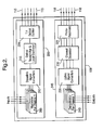
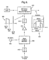
- the base station 100 is seen to comprise two main sections: a downlink transmitting interface 200 and an uplink receiving interface 245. Optical outputs from the downlink interface 200 and optical inputs to the uplink interface 245 are joined by means of an appropriate interface to the optical fibres 115 and 118 respectively linking each of the RAUs 110 to the base station 100.
- Data signals intended for a particular target mobile data terminal 120, 125 are received by the downlink transmitting interface 200 of the base station 100 where a number of modulators 205 are provided, each one dedicated to modulating input data signals in respect of a different data channel.
- a data channel may be used to communicate with one or more mobile terminal units 120, 125 according to the bandwidth requirements of those terminals.
- a single mobile terminal unit 120, 125 would require the entire bandwidth of a data channel for its own use, at least in an uplink direction.
- the base station 100 would be equipped to provide as many data channels as required by the particular application.
- limitations in frequency availability would ultimately limit the number of channels that may be provided.
- use of the 55-65GHz band provides sufficient bandwidth to handle a number of high data rate duplex channels.
- the modulated input signal is input to a downlink signal converter 210 where modulated signals for the respective data channel are converted to a predetermined frequency allocated specifically for the channel.
- the converted signal is then input to an optical transmitter and local oscillator 215 arranged to generate a downlink optical signal, preferably comprising an optical oscillator signal that is modulated by the converted input signal for transmission to the RAUs 110.
- the downlink optical signal output by the optical transmitter 215 includes a separate local oscillator signal that is then available for use, after isolation, by each receiving RAU 110, so avoiding the need to deploy an oscillator of the same frequency at each RAU 110.
- the downlink optical signal is input to an optical splitter 220 where it is divided and injected into each of the downlink optical fibre links 115 by means of an appropriate interface to be conveyed to each of the RAUs 110.
- an alternative technique for dividing the downlink optical signal may be implemented in which lower-order splitters, e.g. 1:4, are deployed in a cascaded arrangement, with erbium-doped fibre amplifiers being used to boost the signal if required.
- lower-order splitters e.g. 1:4
- erbium-doped fibre amplifiers being used to boost the signal if required.
- an initial splitter 220 at the base station 100 may be linked to remote splitters located nearer to the particular RAUs 110 being served to further sub-divide the signals.
- any signals received by one or more RAUs 110 from a mobile data terminal 120, 125 are converted and forwarded to the base station 100 over the uplink optical fibres 118 to arrive at the uplink receiving interface 245.
- the uplink receiving interface 245 includes a set of photo-receivers 225, one photo-receiver for each uplink optical fibre 118, which detects and converts uplink optical signals arriving over the uplink optical fibres 118 into IF signals for input to a channel separator 230.
- Uplink optical signals may comprise a combination of signals for one or more data channels which need to be separated by the base station 100.
- the channel separator 230 is therefore designed to separate the signals for each data channel (and hence for the different mobile data terminals 120, 125) on the basis that the signal for each data channel has a different predetermined frequency. Separated signals for each channel are then input to uplink signal converters 235 where the signals at their respective predetermined frequencies are converted for input to demodulators 240, a different demodulator 240 for each data channel. The demodulated output of each demodulator 235 forms the output from the base station 100, for example to the central terminal unit 105.
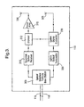
- an RAU 110 is provided with a downlink optical receiver 310 and an uplink optical transmitter 335, each linked by means of an optical interface 305 to the downlink optical fibre 115 and uplink optical fibre 118 respectively that connect the RAU 110 to the base station 100.
- the downlink optical receiver 310 is arranged to receive downlink optical signals transmitted by the base station optical transmitter and local oscillator 215 and to convert the received optical signals into radio frequency (RF) signals.
- the RF signals are input to a diplexer 312 arranged to separate the local oscillator signal generated by the base station optical transmitter 215 from the data signals for one or more data channels.
- the data signals output by the diplexer 312 are amplified by an amplifier 315 and fed to an antenna 320 for wireless transmission by the RAU 110.
- any RF signal transmitted by a mobile data terminal 120, 125 and received at an antenna 325 is passed to an uplink signal converter 330 arranged to convert the received RF signal into an intermediate frequency (IF) data signal.
- the uplink signal converter 330 uses the local oscillator signal separated by the diplexer 312 to convert the received RF signal into the IF data signal which in turn is passed to the uplink optical transmitter 335 to generate an uplink optical signal for transmission to the base station 100 over the uplink optical fibre 118.
- the uplink optical transmitter 335 transmits the IF data signal either by directly modulating a laser diode or by modulating the light from a (CW) laser diode in an external optical modulator.
- wavelength division multiplexing at the RAU 110 and wavelength division demultiplexing at the base station 100 it may be more convenient to use wavelength division multiplexing at the RAU 110 and wavelength division demultiplexing at the base station 100 so that multiple uplink optical signals may be combined onto a single uplink optical fibre 118 serving all the RAUs 110, or at least onto a reduced number of uplink optical fibres 118.
- the laser diode used in the uplink optical transmitter 335 would need to be selected so as to emit light of a wavelength compatible with the wavelength division multiplexer and with the associated channel spacing.
- Figure 3 shows a different antenna (320) being used at an RAU 110 for transmitting signals to that (325) used for receiving signals, the same physical antenna may be used for both transmitting and receiving.
- a different predetermined frequency is allocated to each data channel provided by the base station 100 and RAUs 110.
- the use of a different frequency per data channel provides one of the preferred elements in embodiments of the present invention that enables a single frequency (per mobile data terminal 120, 125) mobile communications network to be operated.
- Another preferred element enabling the single frequency network to operate is the choice of modulation technique implemented by the modulators 205 and demodulators 240 in the base station 100 and replicated in each of the mobile data terminals 120, 125.
- a transmitted signal may be received by a mobile data terminal 120, 125 from two or more different RAUs 110 delayed by slightly different amounts due to their differing distances from the mobile data terminal 120, 125.
- a transmitted signal may be received by a mobile data terminal 120, 125 from two or more different RAUs 110 delayed by slightly different amounts due to their differing distances from the mobile data terminal 120, 125.
- the mobile terminal unit 120 lies within the radio coverage area 130 of a single RAU 110 - "RAU 4" - the other mobile terminal unit 125 lies within a region of overlapping radio coverage for two RAUs 110 - "RAU 2" and "RAU 3".
- a signal transmitted by a mobile data terminal 120, 125 may be received by more than one RAU 110 located within range of the mobile terminal so that each received signal would be forwarded to arrive at the base station 100 at slightly different times.
- the modulation scheme chosen should be inherently tolerant of such signal delays so that received signals may be combined and successfully demodulated by the mobile data terminal 120, 125 in the downlink direction and, in the uplink direction, by the base station 100.
- the modulation scheme selected is the Coded Orthogonal Frequency Division Multiplexing (COFDM) scheme as described, for example, in a book by Mark Massel, entitled “Digital Television: DVB-T COFDM and ATSC 8 - VsB", published by Digitaltvbooks.Com, ISBN 0970493207 .
- COFDM Coded Orthogonal Frequency Division Multiplexing
- COFDM is a form of multi-carrier digital modulation wherein data are modulated onto a large number of closely-spaced carriers whose separation in the frequency domain is carefully chosen so that each carrier is orthogonal to the other carriers, so eliminating interference between them when transmitted simultaneously.
- Each carrier is arranged to send one symbol at a time. The time taken to transmit a symbol is called the symbol duration.
- the symbol duration may be extended by the modulator by the insertion of a so-called guard interval of predetermined length between transmitted symbols on the particular carrier to ensure that the next symbol on the carrier arrives at the receiver after the last delayed arrival of the first symbol.
- each of the downlink optical fibres 115 and each of the uplink optical fibres 118 are of substantially equal length so as to minimise differential time delays in conveying signals between the base station 100 and each of the RAUs 110.
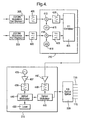
- the downlink transmitting interface 200 of the base station 100 will now be described in more detail, according to a preferred embodiment of the present invention, with reference to Figure 4 .
- the same reference numerals are used to label features shown in Figure 4 that are similar to those in any of the earlier figures.
- the base station 100 provides two communications channels. This two-channel example will be used as the basis for the remainder of the description in the present patent application in order to simplify the figures, although, of course, the base station 100 may be equipped to provide further data channels as required, as will become clear from the description that follows.
- components of a preferred two channel downlink transmitting interface 200 are shown.
- two modems (modulators) 205 are provided, one for each data channel.
- an appropriate one of the two data channels is selected and data is input to the respective modem 205 for that channel.
- the modem 205 modulates the input data signal, preferably according to the COFDM modulation scheme.
- the "I” and “Q” channel outputs from a (COFDM) modem 205 are converted into a combined first intermediate frequency channel by mixing each of the "I” and “Q” signals with a 520 MHz intermediate frequency (IF) oscillator signal, the "Q” signal being mixed with a 520 MHz IF oscillator signal that is a quarter cycle out of phase with that for the "I" signal, and combining the resultant signals.
- the combined signal from each modem 205 is passed through a 520MHz band-pass filter 405 having a bandwidth of approximately 340MHz, to remove any unwanted harmonics and noise that would typically be generated as a result of the preferred IF mixing and combining stage.
- the signal output from the filter 405 for each channel is then input to the downlink signal converter 210 for conversion into a signal of a predetermined frequency allocated for that data channel, preferably in the range 1.5 to 3.5GHz.
- the downlink signal converter 210 comprises, for each data channel, a mixer 410 and a local oscillator (LO) 415, 418.
- the frequencies of the local oscillators 415, 418 are selected to ensure that when the oscillator signal is mixed (410) with the output signal from the filter 405, a signal of the predetermined frequency for that channel is generated.
- the frequencies of the local oscillators 415, 418, and hence the predetermined frequencies for the channels are selected so as to minimise unwanted mixing products generated as a result of mixing the signal from the local oscillators 415, 418 with the output signals from the filters 405, bearing in mind the particular combination of frequencies used to generate those output signals.
- the local oscillator 415 for one of the channels is preferably set to a frequency of 1.43GHz and the local oscillator 418 for the other channel is set to a frequency of 2.68GHz.
- n modems 205, filters 405, mixers 410 and local oscillators 415, 418 would typically need to be provided, each local oscillator being set to a different frequency such as to generate a channel signal within a predetermined frequency range, e.g. 1.5-3.5GHz.
- the process of selecting channel frequencies and hence corresponding oscillator frequencies takes place as part of an overall design stage for the apparatus.
- a switching arrangement can be implemented to enable different local oscillators to be selected to enable switching between data channels and hence communication with different mobile terminal units 120, 125.
- tuneable local oscillators may be provided to achieve a similar effect.
- the output from the mixer 410 comprises not only a signal at the allocated frequency for the data channel but also signals at one or more other frequencies.
- a filter 420, 423 is used therefore to remove the unwanted components from the mixer output signal leaving only a signal of the allocated frequency for the data channel.
- the filters 420 and 423 are band-pass filters centred on frequencies of 1.95GHz and 3.2GHz respectively, both having a bandwidth greater than or equal to 340MHz.
- the signals emerging from the filters 420 and 423, each of a distinct frequency are combined in a combiner 425 to form a composite signal for input to the optical transmitter 215.
- the combiner 425 in the present example is a 2:1 combiner because there are only two data channels. If the base station 100 was equipped to provide n channels, then an n:1 combiner would be provided to combine the signals into a single composite channel.
- the optical transmitter 215 is constructed according to a cascaded optical modulator design.
- An optical carrier generated by a laser 430 is optically coupled using polarisation maintaining optical fibre to a first optical modulator 440 arranged to modulate the optical carrier with an amplified (437) and filtered (439) oscillator signal generated by an oscillator 435 to form an optical oscillator signal and, in a second optical modulator 445, optically coupled using polarisation maintaining optical fibre to the first optical modulator 440, the optical oscillator signal is modulated with an amplified (447) and filtered (449) composite signal output by the combiner 425.
- the frequency of the oscillator 435 is selected to ensure that a signal is output from the second optical modulator 445 having a predetermined frequency suitable for wireless transmission by the RAUs 110.
- This predetermined frequency would be required to fall within a range of frequencies for which a licence to transmit has been granted. In preferred embodiments of the present invention this range of frequencies is chosen to be 57-59GHz for the downlink and 62-64GHz for the uplink, with a local oscillator frequency of 60.5GHz.
- the downlink optical signal output by the second optical modulator 445 is split by the optical splitter 220 and injected into each of the downlink optical fibres 115 linking the base station 100 with the RAUs 110.
- the optical modulators 440 and 445 are preferably commercially available high frequency Mach-Zehnder (MZ) optical modulators.
- the first optical modulator 440 is biased at the minimum of its transfer characteristic so that a frequency-doubling effect can be achieved in modulating the laser light (430), preferably output by 50mW DFB laser diode 430, with the amplified oscillator signal (435,437, 439).
- Frequency doubling may be achieved by biasing the first optical modulator 440 at either its maximum or minimum. However, it is preferable to bias at the minimum point as this minimises the dc light level at a photo-receiver and thus provides the best noise performance.
- a MZ modulator Making use of the frequency doubling properties of a MZ modulator enables an oscillator 435 having a frequency of only 30.25GHz to be used to generate a 60.5GHz oscillator signal in the optical output from the first MZ optical modulator 440 - in fact two optical oscillator sideband signals are generated, as shown (505) in Figure 5 , separated by 60.5GHz - the laser carrier itself (430) being suppressed.
- the second MZ optical modulator 445 is biased at the quadrature point, the most linear region of its transfer characteristic.
- each of the optical oscillator sidebands is modulated resulting in a pair of optical data signal sidebands centred about each of the optical oscillator sidebands, as shown (510) in Figure 5 , the first pair in the frequency range 57-59GHz and the second in the range 62-64GHz respectively in the present example, corresponding to the composite IF data signal frequency range of 1.5 to 3.5GHz.
- Each data signal sideband is separated, in the frequency domain, from the optical oscillator sideband signals according to the frequencies of the signal components within the composite IF data signal.
- the downlink optical signal output by the second MZ optical modulator 445 is then injected into each of the downlink optical fibres 115 for sending to the RAUs 110.
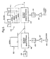
- the downlink optical signal output by the optical transmitter 215 at the base station 100 is received over the downlink optical fibre 115 at an optical interface 305 and passed to an optical receiver 310 comprising a photo-receiver 605.
- the RF electrical outputs from the photo-receiver 605 are the 60.5GHz local oscillator signal, as generated by the base station optical transmitter 215, and the lower and upper data signal sidebands in the frequency ranges 57-59GHz and 62-64GHz respectively (60.5GHz ⁇ 1.5-3.5GHz).
- the RF signals are amplified in an amplifier 610 and input to a diplexer 312 arranged to separate the local oscillator signal from the data signal sidebands.
- the lower frequency sideband in the range 57-59GHz is retained as the downlink signal for transmission by the RAU 110, while the upper frequency sideband is blocked by means of a band-pass filter 615 that permits only the lower frequency band to pass to the power amplifier 315 and then by means of an isolator 620 to the downlink antenna 320.
- the separated local oscillator signal is passed to the uplink signal converter 330 for use in converting received mm-wave uplink signals into IF uplink signals.
- a mm-wave signal transmitted by a mobile data terminal 120, 125 and received at the RAU 110 by the antenna 325 is passed by means of an isolator 635 to the uplink signal converter 330.
- the received uplink signal is first filtered in a band-pass filter 640 arranged to allow signals in the range 62-64GHz to pass - the preferred frequency range for uplink communications in the present example - then amplified in an amplifier 645 and input to a mixer 650.
- the separated 60.5GHz local oscillator signal from the diplexer 312 is filtered in a 60.5GHz band-pass filter and amplified by an amplifier 630 before input to the mixer 650.
- the result of mixing the 60.5GHz local oscillator signal with the received uplink signal is, amongst other mixing products, an uplink IF signal in the frequency range 1.5-3.5GHz.
- the mixer output is amplified in an amplifier 655 before filtering out all but the uplink IF signal in the frequency range 1.5-3.5GHz in a band-pass filter 660.
- the uplink signal converter 330 outputs the uplink IF signal to the uplink optical transmitter 335.
- the uplink optical transmitter 335 comprises an optical modulator 670 to modulate the uplink IF signal onto an optical carrier signal provided by a laser 675 to generate an uplink optical signal which is then injected into the uplink optical fibre 118 to the base station 100.
- the uplink receiving interface 245 of the base station 100 will now be described in more detail according to a preferred embodiment of the present invention with reference to Figure 7 .
- the same reference numerals are used to label features shown in Figure 7 that are similar to those in any of the earlier figures.
- the uplink receiving interface 245 in this example is arranged to interface with any combination of three RAUs 110, although of course the base station 100 may be scaled to interface with further RAUs 110 as will be clear from this description.
- Uplink optical signals received over any of the three uplink optical fibres 118 are detected by a photo-receiver 225 linked to that uplink optical fibre 118 by an appropriate interface.
- the photo-receiver 225 converts the received uplink optical signal into an uplink IF signal similar to that generated by the uplink signal converter 330 within the RAU 110.
- a different photo-receiver 225 is provided to receive signals from each of the three uplink optical fibres 118.
- the uplink IF signal output by each of the photo-receivers 225 is then input to the channel separator 230.
- Uplink optical signals received from an RAU 110 may carry signals for more than one data channel simultaneously if the RAU 110 was within range of multiple transmitting mobile terminal units 120, 125.
- the channel separator 230 is designed to separate the signals for each of the data channels and, where signals for a given data channel are separately received from more than one RAU 110, to combine all the received signals for a given data channel so as to output a combined channel signal for each channel.
- the three uplink optical fibre inputs 118 convert to two channel outputs from the channel separator 230.
- the signals for each data channel are distinguished by their differing frequencies.
- the channel separator 230 splits the uplink IF signal from each photo-receiver 225 along two signal paths, one signal path per data channel, using a splitter 710.
- one signal path leads to a 1.95GHz band-pass filter 715 to pass signals at the allocated frequency for the first data channel and the other signal path leads to a 3.2GHz band-pass filter 720 to pass signals at the allocated frequency for the second data channel.
- the uplink signal converter 235 comprises, for each data channel, a mixer 740, 742 and a local oscillator 745, 748.
- the local oscillators 745, 748 operate at the same frequencies as the local oscillators 415 and 418 respectively in the downlink transmitting interface 210 described above.
- the combined uplink IF signals for each channel are received at the respective mixer 740, 742 and mixed with the corresponding local oscillator signals.
- the resultant signals are then amplified by a respective IF amplifier 750, 752.
- the mixers 740, 742 generate a number of signal components of which only one is required. Therefore a band-pass filter 755, 758 is used to block the unwanted signal components for each channel before the required uplink signal components are output to be demodulated in respective COFDM demodulators 240.
- the modems 240 are COFDM modems.
- the demodulated data signal for each channel is then output from the modem 240, for example to the central terminal unit 105.
- a preferred mobile transmit/receive interface will now be described, with reference to Figure 8 , for use in a mobile terminal unit 120, 125 to enable communication with the base station 100 via the RAUs 110.
- the mobile transmit/receive interface may be physically mounted and electronically connected to a movable television camera to enable the camera to transmit image data to and receive control data from a central studio, for example, by means of the RAUs 110 and base station 100.
- components in a preferred mobile terminal unit 120, 125 are shown, including a data source 805, a TV camera for example, linked for uplink communications to the mobile transmit/receive interface 810 by means of a COFDM modulator 815.
- a downlink signal output from the mobile transmit/receive interface 810 is demodulated in a COFDM demodulator 820 for output (825) to a TV monitor, for example.
- Both the COFDM modulator 815 and demodulator 820 are arranged to cooperate with the demodulators 240 and modulators 205 respectively, as used in the base station 100.
- the COFDM modulator 815 includes circuitry to convert a baseband modulated signal into an IF uplink data signal of a predetermined frequency specific to that mobile transmit/receive interface 810, either 1.95GHz or 3.2GHz in the present two-channel example.
- the COFDM demodulator 820 includes circuitry to convert a downlink IF data signal into a signal of the required frequency for demodulation by the COFDM demodulator 820.
- the mobile transmit/receive interface is going to be used to communicate on only one of the data channels supported by the base station 100, although a switching arrangement can be provided at the mobile terminal unit 120, 125 if required to enable switching between channel frequencies in a similar manner to that mentioned above in describing the operation of a preferred base station 100.
- a signal input by the data source 805 is COFDM modulated and converted (815) into an IF uplink data signal.
- the mobile transmit/receive interface 810 receives the uplink IF data signal and amplifies it in an IF amplifier 830 and mixes the amplified signal in a mixer 835 with a 60.5GHz local oscillator signal, in the present example, generated by a local oscillator 840.
- the mixer output is then filtered in a band-pass filter to block all but those mixer products in the preferred uplink wireless communication frequency range of 62-64GHz.
- the uplink data signal is transmitted wirelessly by means of an antenna 855 to be received by one or more RAUs 110.
- a signal transmitted by one or more RAUs 110 in the preferred downlink wireless communication frequency range of 57-59GHz for the present example, is received at an antenna 860.
- the received downlink signal is filtered in a 57-59GHz band-pass filter 865 and amplified in a low-noise amplifier (LNA) 870 before input to a mixer 875 arranged to mix the amplified signal with the local oscillator signal from oscillator 840.
- LNA low-noise amplifier
- One of the results of mixing the oscillator signal with a signal in the range 57-59GHz is a downlink IF data signal in the frequency range 1.5-3.5GHz.
- All other mixer products are blocked in a band-pass filter 880, leaving the downlink IF data signal to be amplified in an IF amplifier 885 for output from the mobile transmit/receive interface 810.
- the output IF data signal is converted and demodulated in the COFDM demodulator 820 and output (825), for example to a TV monitor.
- a preferred optical transmitter is shown constructed according to a so-called RF single sideband frequency-doubled design.
- the composite signal output by the combiner 425 is firstly filtered in a 1.5-3.5GHz band-pass filter 449 before input to a single-sideband non-suppressed carrier electrical modulator 905 to modulate an RF oscillator signal generated by the oscillator 435. It is important that the oscillator carrier signal is not suppressed by the modulator as the oscillator signal will be included in the signal transmitted to the RAUs 110.
- the resulting single-sideband signal and the oscillator signal output by the modulator 905 are further amplified (910) and filtered in a 30.5GHz low-pass filter 915 to provide additional rejection of any unwanted upper sideband signal.
- the resultant single-sideband signal and oscillator signal, shown (920) in Figure 9 are input to a MZ optical modulator 440 biased at the minimum of its transfer characteristic, as for the first optical modulator in the cascaded optical modulator design described above with reference to Figure 5 , so as to achieve frequency doubling and suppression of the optical carrier input from a laser 430.
- the laser 430 is optically coupled using polarisation maintaining optical fibre to the MZ optical modulator 440 where the optical carrier is modulated by the single-sideband and oscillator signal (920).
- the result (shown as 925 in Figure 9 ) is a downlink optical signal comprising a pair of local oscillator signals separated by 60.5GHz together with two downlink data sidebands separated, in the frequency domain, from the oscillator signal according to the frequency of the single-sideband signal (920).
- the frequencies of the single-sideband and oscillator signals input to the MZ modulator 440 are doubled, the frequency separation of the oscillator and sideband signal components is maintained after modulation - an important feature that enables this design of optical transmitter 215 to be used as an alternative to the cascaded optical transmitter design described above with reference to Figure 5 without needing to modify the design of the other components of the apparatus or the mobile terminal units 120, 125.
- the downlink optical signal output by the MZ optical modulator 440 is shown as 925 in Figure 5 . This signal is injected into the downlink optical fibres 115 for communication to the RAUs 110.
- each of the antennae are designed for use with signals in the frequency range 57 to 64GHz, although it would be apparent to a person of ordinary skill in the field of antenna design that the antennae may be designed to operate in other frequency ranges according to the particular application of the apparatus of the present invention.
- the preferred antenna 1000 is a rotationally symmetric shaped-dielectric lens antenna comprising a dielectric lens portion 1005, preferably made from PTFE, mounted on a conducting mounting plate 1010.
- the dielectric lens 1005 is of a known shape designed to produce a substantially sec 2 ⁇ radiation power pattern, where ⁇ is the angle measured from the axis of symmetry through the antenna 1000, for angles of ⁇ up to approximately 70°.
- This power pattern has been found to be suitable for use in an enclosed environment such as a television studio where the antenna is attached to the ceiling near to the centre of the space.
- This design forms a good compromise for use in such environments over an alternative known, but more complex, lens design capable of producing substantially rectangular radiation fields.
- FIG. 10b a plane section through the antenna 1000 is shown, taken through the plane indicated by the line A-A in Figure 10a .
- the shaped dielectric lens 1005 is attached to the conducting mounting plate 1010 by means of four fixing bolts 1015, each made, optionally, from a similar material to that used for the dielectric lens 1005 itself, although metal bolts may also be used.
- Each bolt 1015 engages with a corresponding threaded hole provided in a projecting annular portion 1016 of the dielectric lens 1005 which itself engages with a corresponding annular recess 1018 provided in the mounting plate 1010.
- a hole 1020 is provided through the centre of the mounting plate 1010 to provide a point of entry for a waveguide 1025 assembly.
- the waveguide assembly 1025 comprises an air-filled polariser, of conventional design, arranged in two parts to emit radiation with circular polarisation into the dielectric lens: a rectangular-sectioned portion 1030 leading to a flattened circular sectioned portion 1035, with appropriately shaped transition sections 1040 and 1045 disposed between the rectangular 1030 and flattened circular 1035 air-filled sections and between the air-filled flattened circular 1035 and dielectric-filled entry hole 1020, respectively.
- That portion of the hole 1020 not occupied by the waveguide feeder transition section 1045 is filled with dielectric material, preferably the same material as that used for the lens 1005 itself.
- a portion of the dielectric material may have a central bore or alternatively have its external radius reduced in order to provide an impedance matching section between the air-filled circular waveguide and dielectric-filled entry hole.
- an axially-symmetric pattern of circular grooves 1050 is cut into the surface of the dielectric lens to help to reduce the effects of internal reflections within the lens, in a known manner.
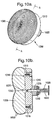
- a plan view of a preferred shaped radiation pattern antenna 1100 is shown for use with a mobile terminal unit 120, 125.
- the preferred antenna 1100 is a rotationally symmetric shaped-dielectric lens antenna comprising a dielectric lens portion 1105, also preferably made from PTFE, mounted on a conducting mounting plate 1110.
- the dielectric lens 1105 is shaped according to a known shape designed to produce a substantially hemispherical radiation power pattern.
- FIG. 11b a plane section through the antenna 1100 is shown, taken through the plane indicated by the line B-B in Figure 11 a.
- the shaped dielectric lens 1105 is attached to the conducting mounting plate 1110 by means of a projecting annular portion 1115 which engages with a corresponding annular recess 1118 provided in the mounting plate 1110.
- a hole 1120 is provided through the centre of the mounting plate 1110 as a point of entry for a waveguide 1125 assembly.
- the waveguide assembly 1125 is similar in design to that (1025) used with the RAU antenna 1000 of Figure 10 , although with a smaller diameter feed 1130 into the dielectric lens 1105 to give a wider radiation pattern and hence a wider illumination of the lens 1105.
- the effect of internal reflections on the radiation pattern has been found to be greater than that with the RAU antenna 1000, in particular on the radiation pattern towards the outer limits of the field between 70° and 90° as measured from the axis of symmetry of the lens. It is has been found, however, that if an annular portion 1135 of a radiation absorbing material, for example Emerson & Cuming "Eccosorb AN-72"TM, is disposed in an annular recess formed towards the outer edge of the mounting plate 1110, a recess formed preferably by extending the width of the recess 1118 radially outwards, then the effect of the internal reflections can be considerably reduced.
- the projecting annular portion 1115 of dielectric material together with the annular portion of absorber material 1135 together fill the extended annular recess 1118 in the mounting plate 1110 to provide a secure attachment of the dielectric lens 1105 to the mount 1110.
- the surface of the dielectric lens 1105 of the mobile terminal unit antenna 1100 is provided with a pattern of circular grooves 1140 to reduce internal reflections.
- a single mobile terminal unit 120, 125 may require the entire bandwidth of a data channel
- a number of mobile terminal units may share a given data channel and the associated base station equipment by using a combination of Time Division Multiplexing (TDM) and Frequency Division Multiplexing (FDM). This would involve allocating time intervals to a group of mobile users who all operate at one frequency. There would be a number of these 'groups' operating at different frequencies.
- TDM Time Division Multiplexing
- FDM Frequency Division Multiplexing
Claims (15)
- Eine Vorrichtung, die betriebsfähig ist, um Daten zwischen einer ersten und einer zweiten Endgeräteinheit zu kommunizieren, wobei mindestens eine der ersten und zweiten Endgeräteinheit eine mobile Endgeräteinheit (120) ist, wobei die Vorrichtung Folgendes beinhaltet:eine Basisstation (100) undeine Vielzahl von Antenneneinheiten (110) mit unterschiedlichen Abdeckbereichen (130), wobei jede Antenneneinheit (110) mit der Basisstation (100) verknüpft ist und betriebsfähig ist, um aus der Basisstation (100) empfangene modulierte Datensignale drahtlos zu übertragen und drahtlos empfangene modulierte Datensignale an die Basisstation (100) weiterzuleiten,wobei die Basisstation (100) Folgendes beinhaltet:ein Übertragungsgerät zum Übertragen modulierter Datensignale an jede der Vielzahl von Antenneneinheiten (110) zur drahtlosen Übertragung;einen Empfänger zum Empfangen modulierter Datensignale, die von mindestens einer der Vielzahl von Antenneneinheiten (110) weitergeleitet werden;einen Modulator zum Erzeugen modulierter Datensignale bezüglich eines gegebenen Datenkanals gemäß eines vorbestimmten Modulationsschemas, wodurch aufeinanderfolgende Blöcke modulierter Daten in dem Datenkanal durch mindestens eine minimale Zeitperiode, die für eine gegebene Anordnung der Vorrichtung bestimmt ist, zeitlich innerhalb des Datenkanals getrennt werden, so dass mindestens die minimale Zeitperiode zwischen den Ankünften der aufeinanderfolgenden Blöcke modulierter Daten an der mobilen Endgeräteinheit (120) verstreicht, und wobei die vorbestimmte minimale Zeitperiode für die gegebene Anordnung der Vorrichtung festgelegt ist, um im Wesentlichen der maximalen erwarteten Differenz des Zeitintervalls, das zur Kommunikation eines gegebenen Datenblocks zwischen der Basisstation (100) und der mobilen Endgeräteinheit (120) mittels unterschiedlicher der Vielzahl von Antenneneinheiten (110) erforderlich ist, zu entsprechen; undeinen Demodulator zum Demodulieren von von dem Empfänger empfangenen Datensignalen, die gemäß dem vorbestimmten Modulationsschema moduliert worden sind.
- Vorrichtung gemäß Anspruch 1, wobei die vorbestimmte minimale Zeitperiode auf der Basis der unterschiedlichen erwarteten Verzögerungen der Kommunikation des gegebenen Datenblocks aufgrund von Mehrwegeffekten in der gegebenen Anordnung der Vorrichtung bestimmt wird.
- Vorrichtung gemäß Anspruch 1 oder Anspruch 2, wobei jede der Vielzahl von Antenneneinheiten (110) mittels mindestens einer Glasfaserübertragungsleitung (115, 118) mit der Basisstation (100) verknüpft ist und wobei das Übertragungsgerät und der Empfänger optoelektronische Einrichtungen sind.
- Vorrichtung gemäß einem der Ansprüche 1 bis 3, die betriebsfähig ist, um mindestens zwei Datenkanäle zum Kommunizieren mit der mindestens einen mobilen Endgeräteinheit (120) bereitzustellen, wobei zum Kommunizieren von Daten über jeden der Datenkanäle ein anderer vorbestimmter Frequenzbereich zugeordnet ist.
- Vorrichtung gemäß Anspruch 4, wobei jeder der vorbestimmten Frequenzbereiche in dem Bereich von 55 GHz bis 65 GHz liegt.
- Vorrichtung gemäß Anspruch 4 oder Anspruch 5, wobei die Basisstation (100) ferner Kanaltrennmittel zum Trennen von Signalen beinhaltet, die sich auf jeden der mindestens zwei Datenkanäle beziehen, wenn innerhalb eines aus einer der Vielzahl von Antenneneinheiten (110) an dem Empfänger empfangenen modulierten Datensignals enthalten.
- Vorrichtung gemäß Anspruch 6, wobei die Basisstation (100) ferner Kombiniermittel, die für jeden der mindestens zwei Datenkanäle betriebsfähig sind, um entsprechende getrennte Signale, die aus mindestens zwei der Vielzahl von Antenneneinheiten (110) empfangen werden, zu kombinieren, beinhaltet.
- Vorrichtung gemäß einem der vorhergehenden Ansprüche,
wobei das vorbestimmte Modulationsschema ein COFDM-Schema ist und wobei die vorbestimmte minimale Zeitperiode mittels eines Schutzintervalls, das durch einen COFDM-Modulator zwischen modulierte Symbole eingefügt wird, erreicht wird. - Vorrichtung gemäß Anspruch 3, wobei jede der Vielzahl von Antenneneinheiten (110) mittels einer im Wesentlichen gleichen Länge einer Glasfaserübertragungsleitung mit der Basisstation (100) verknüpft ist, um die Verzögerungen beim Kommunizieren von Signalen zwischen der Basisstation (100) und jeder der Vielzahl von Antenneneinheiten (110) auszugleichen.
- Ein Verfahren zum Kommunizieren von Daten zwischen einer ersten mobilen Endgeräteinheit (120) und einer zweiten Endgeräteinheit über einen Datenkanal, der mittels einer Vielzahl von Antenneneinheiten (110) mit unterschiedlichen Abdeckbereichen (130) aufgebaut ist, und wobei jede der Vielzahl von Antenneneinheiten (110) mit einer Basisstation (100), die der zweiten Endgeräteinheit zugehörig ist, verknüpft ist, wobei das Verfahren die folgenden Schritte beinhaltet:(i) Erzeugen eines modulierten Datensignals gemäß einem vorbestimmten Modulationsschema an der ersten mobilen Endgeräteinheit (120);(ii) drahtloses Übertragen des modulierten Datensignals zum Empfang durch mindestens eine der Vielzahl von Antenneneinheiten (110) und(iii) Demodulieren des empfangenen modulierten Datensignals in dem Datenkanal a der zugehörigen Basisstation (100) zur Kommunikation zu der zweiten Endgeräteinheit,
wobei gemäß dem vorbestimmten Modulationsschema in Schritt (i) aufeinanderfolgende Blöcke modulierter Daten in dem Datenkanal durch mindestens eine minimale Zeitperiode, die für eine gegebene Anordnung der Vorrichtung bestimmt ist, zeitlich innerhalb des Datenkanals getrennt werden, so dass mindestens die minimale Zeitperiode zwischen den Ankünften der aufeinanderfolgenden Blöcke modulierter Daten an der Basisstation (100) verstreicht, und wobei die vorbestimmte minimale Zeitperiode für die gegebene Anordnung der Vorrichtung festgelegt ist, um im Wesentlichen der maximalen erwarteten Differenz des Zeitintervalls, das zur Kommunikation eines gegebenen Datenblocks zwischen der mobilen Endgeräteinheit (120) mittels unterschiedlicher der Vielzahl von Antenneneinheiten (110) und der Basisstation (100) erforderlich ist, zu entsprechen. - Verfahren gemäß Anspruch 10, wobei die vorbestimmte minimale Zeitperiode auf der Basis der unterschiedlichen erwarteter Verzögerungen der Kommunikation des gegebenen Datenblocks aufgrund von Mehrwegeffekten in der gegebenen Anordnung der Vorrichtung bestimmt wird.
- Verfahren gemäß Anspruch 10 oder Anspruch 11, wobei ein Datensignal über einen ausgewählten der mindestens zwei Datenkanäle kommuniziert werden kann und wobei in Schritt (i) das modulierte Datensignal in ein Signal in einem entsprechenden vorbestimmten Frequenzbereich, der zum Kommunizieren von Daten über den ausgewählten Datenkanal zugewiesen ist, konvertiert wird.
- Verfahren gemäß Anspruch 12, wobei jeder der vorbestimmten Frequenzbereiche in dem Bereich von 55 GHz bis 65 GHz liegt.
- Verfahren gemäß Anspruch 12 oder Anspruch 13, das ferner die folgenden Schritte beinhaltet:(iii) Empfangen des über den ausgewählten Datenkanal kommunizierten modulierten Datensignals an der Basisstation (100);(iv) Führen des empfangenen modulierten Datensignals durch einen Kanalseparator, der angeordnet ist, um empfangene modulierte Datensignale gemäß ihrem Kanalfrequenzbereich zu trennen;(v) Kombinieren der modulierten Datensignale, die für den ausgewählten Datenkanal empfangen werden, im Fall, dass das empfangene modulierte Datensignal aus zwei oder mehreren der Vielzahl von Antenneneinheiten empfangen wird; und(vi) Demodulieren des empfangenen modulierten Datensignals für den ausgewählten Datenkanal, insbesondere, wenn kombiniert.
- Verfahren gemäß einem der Ansprüche 10 bis 14, wobei das vorbestimmte Modulationsschema ein COFDM-Schema ist und
wobei die vorbestimmte minimale Zeitperiode mittels eines Schutzintervalls, das in Schritt (i) beim Erzeugen des modulierten Datensignals zwischen modulierte Symbole eingefügt wird, erreicht wird.
Priority Applications (1)
| Application Number | Priority Date | Filing Date | Title |
|---|---|---|---|
| EP05798426A EP1825700B1 (de) | 2004-11-15 | 2005-10-27 | Datenkommunikationsvorrichtung mit mehreren antennen |
Applications Claiming Priority (4)
| Application Number | Priority Date | Filing Date | Title |
|---|---|---|---|
| EP04257066 | 2004-11-15 | ||
| GB0425148A GB0425148D0 (en) | 2004-11-15 | 2004-11-15 | Data communications |
| EP05798426A EP1825700B1 (de) | 2004-11-15 | 2005-10-27 | Datenkommunikationsvorrichtung mit mehreren antennen |
| PCT/GB2005/004163 WO2006051263A1 (en) | 2004-11-15 | 2005-10-27 | Data communication apparatus with multiple antennas |
Publications (2)
| Publication Number | Publication Date |
|---|---|
| EP1825700A1 EP1825700A1 (de) | 2007-08-29 |
| EP1825700B1 true EP1825700B1 (de) | 2009-12-09 |
Family
ID=35429629
Family Applications (1)
| Application Number | Title | Priority Date | Filing Date |
|---|---|---|---|
| EP05798426A Active EP1825700B1 (de) | 2004-11-15 | 2005-10-27 | Datenkommunikationsvorrichtung mit mehreren antennen |
Country Status (8)
| Country | Link |
|---|---|
| US (1) | US7720510B2 (de) |
| EP (1) | EP1825700B1 (de) |
| JP (1) | JP4445015B2 (de) |
| AT (1) | ATE451808T1 (de) |
| AU (1) | AU2005303661B2 (de) |
| DE (1) | DE602005018258D1 (de) |
| ES (1) | ES2337381T3 (de) |
| WO (1) | WO2006051263A1 (de) |
Families Citing this family (51)
| Publication number | Priority date | Publication date | Assignee | Title |
|---|---|---|---|---|
| US20090067843A1 (en) * | 2007-07-17 | 2009-03-12 | Way Winston I | Optical Wavelength-Division-Multiplexed (WDM) Comb Generator Using a Single Laser |
| EP2203799A4 (de) | 2007-10-22 | 2017-05-17 | Mobileaccess Networks Ltd. | Kommunikationssystem mit leitungen mit niedriger bandbreite |
| US8175649B2 (en) | 2008-06-20 | 2012-05-08 | Corning Mobileaccess Ltd | Method and system for real time control of an active antenna over a distributed antenna system |
| WO2010091004A1 (en) | 2009-02-03 | 2010-08-12 | Corning Cable Systems Llc | Optical fiber-based distributed antenna systems, components, and related methods for calibration thereof |
| EP2394378A1 (de) | 2009-02-03 | 2011-12-14 | Corning Cable Systems LLC | Verteilte antennensysteme auf glasfaserbasis, bestandteile und entsprechende verfahren zur überwachung und konfigurierung dafür |
| US9673904B2 (en) | 2009-02-03 | 2017-06-06 | Corning Optical Communications LLC | Optical fiber-based distributed antenna systems, components, and related methods for calibration thereof |
| CN102232191B (zh) | 2009-02-08 | 2015-07-08 | 康宁移动接入有限公司 | 采用携带以太网信号的电缆的通信系统 |
| US8280259B2 (en) | 2009-11-13 | 2012-10-02 | Corning Cable Systems Llc | Radio-over-fiber (RoF) system for protocol-independent wired and/or wireless communication |
| US8275265B2 (en) | 2010-02-15 | 2012-09-25 | Corning Cable Systems Llc | Dynamic cell bonding (DCB) for radio-over-fiber (RoF)-based networks and communication systems and related methods |
| CN103119865A (zh) * | 2010-08-16 | 2013-05-22 | 康宁光缆系统有限责任公司 | 支持远程天线单元之间的数字数据信号传播的远程天线集群和相关系统、组件和方法 |
| US9252874B2 (en) | 2010-10-13 | 2016-02-02 | Ccs Technology, Inc | Power management for remote antenna units in distributed antenna systems |
| EP2451089B1 (de) * | 2010-11-08 | 2016-01-27 | Gilat Satellite Networks, Ltd. | Mehrträger-Satellitennetzwerk mit Unterstützung heterogener Endgeräte |
| EP2678972B1 (de) | 2011-02-21 | 2018-09-05 | Corning Optical Communications LLC | Bereitstellung digitaler datendienste als elektrische signale und hochfrequenz (hf)-kommunikationen über glasfasern in verteilten kommunikationssystemen sowie entsprechende komponenten und verfahren |
| EP2702710A4 (de) | 2011-04-29 | 2014-10-29 | Corning Cable Sys Llc | Bestimmung der weiterleitungsverzögerung von kommunikationen in verteilten antennensystemen sowie entsprechende komponenten, systeme und verfahren |
| EP2702780A4 (de) | 2011-04-29 | 2014-11-12 | Corning Cable Sys Llc | Systeme, verfahren und vorrichtungen zur erhöhung einer hochfrequenz (hf)-leistung in verteilten antennensystemen |
| GB201113132D0 (en) * | 2011-07-29 | 2011-09-14 | Bae Systems Plc | Radio frequency communication |
| EP2829152A2 (de) | 2012-03-23 | 2015-01-28 | Corning Optical Communications Wireless Ltd. | Rfic-chip(s) zur bereitstellung von funktionalitäten eines verteilten antennensystems sowie entsprechende komponenten, systeme und verfahren |
| EP2842245A1 (de) | 2012-04-25 | 2015-03-04 | Corning Optical Communications LLC | Verteilte antennensystemarchitekturen |
| EP2670210B1 (de) * | 2012-06-01 | 2014-09-17 | Ntt Docomo, Inc. | System zur Implementierung eines Funks über Faserübertragung in einem passiven optischen Netzwerk |
| JP2013257212A (ja) * | 2012-06-12 | 2013-12-26 | Ricoh Co Ltd | 照明装置、通信装置及び位置情報管理システム |
| EP2883416A1 (de) | 2012-08-07 | 2015-06-17 | Corning Optical Communications Wireless Ltd. | Verteilung von zeitlich gemultiplexten (tdm) management-diensten in einem verteilten antennensystem sowie entsprechende komponenten, systeme und verfahren |
| US9143785B2 (en) | 2012-10-25 | 2015-09-22 | Allen LeRoy Limberg | COFDM broadcast systems employing turbo coding |
| US9455784B2 (en) * | 2012-10-31 | 2016-09-27 | Corning Optical Communications Wireless Ltd | Deployable wireless infrastructures and methods of deploying wireless infrastructures |
| US9647758B2 (en) | 2012-11-30 | 2017-05-09 | Corning Optical Communications Wireless Ltd | Cabling connectivity monitoring and verification |
| JP6141087B2 (ja) * | 2013-04-23 | 2017-06-07 | 日本放送協会 | 送り返し信号遅延補正装置 |
| WO2014199384A1 (en) | 2013-06-12 | 2014-12-18 | Corning Optical Communications Wireless, Ltd. | Voltage controlled optical directional coupler |
| EP3008828B1 (de) | 2013-06-12 | 2017-08-09 | Corning Optical Communications Wireless Ltd. | Zeitduplexierung (tdd) in verteilten kommunikationssystemen, einschliesslich verteilten antennensystemen (dass) |
| US9247543B2 (en) | 2013-07-23 | 2016-01-26 | Corning Optical Communications Wireless Ltd | Monitoring non-supported wireless spectrum within coverage areas of distributed antenna systems (DASs) |
| US9661781B2 (en) | 2013-07-31 | 2017-05-23 | Corning Optical Communications Wireless Ltd | Remote units for distributed communication systems and related installation methods and apparatuses |
| US9385810B2 (en) | 2013-09-30 | 2016-07-05 | Corning Optical Communications Wireless Ltd | Connection mapping in distributed communication systems |
| US9178635B2 (en) | 2014-01-03 | 2015-11-03 | Corning Optical Communications Wireless Ltd | Separation of communication signal sub-bands in distributed antenna systems (DASs) to reduce interference |
| US9775123B2 (en) | 2014-03-28 | 2017-09-26 | Corning Optical Communications Wireless Ltd. | Individualized gain control of uplink paths in remote units in a distributed antenna system (DAS) based on individual remote unit contribution to combined uplink power |
| US9357551B2 (en) | 2014-05-30 | 2016-05-31 | Corning Optical Communications Wireless Ltd | Systems and methods for simultaneous sampling of serial digital data streams from multiple analog-to-digital converters (ADCS), including in distributed antenna systems |
| CN106576391B (zh) * | 2014-06-23 | 2021-02-02 | 意大利电信股份公司 | 集中式无线电接入网络中的前传载荷动态减少 |
| EP3186903A2 (de) | 2014-08-25 | 2017-07-05 | Corning Optical Communications Wireless Ltd. | Unterstützung einer zusatz-remoteeinheit in einem optischen glasfaserbasierten verteilten antennensystem (das) über ein bestehendes glasfaserkommunikationsmedium mittels hochfrequenz (hf)-multiplexen |
| US9730228B2 (en) | 2014-08-29 | 2017-08-08 | Corning Optical Communications Wireless Ltd | Individualized gain control of remote uplink band paths in a remote unit in a distributed antenna system (DAS), based on combined uplink power level in the remote unit |
| US9602210B2 (en) | 2014-09-24 | 2017-03-21 | Corning Optical Communications Wireless Ltd | Flexible head-end chassis supporting automatic identification and interconnection of radio interface modules and optical interface modules in an optical fiber-based distributed antenna system (DAS) |
| US9420542B2 (en) | 2014-09-25 | 2016-08-16 | Corning Optical Communications Wireless Ltd | System-wide uplink band gain control in a distributed antenna system (DAS), based on per band gain control of remote uplink paths in remote units |
| US10659163B2 (en) | 2014-09-25 | 2020-05-19 | Corning Optical Communications LLC | Supporting analog remote antenna units (RAUs) in digital distributed antenna systems (DASs) using analog RAU digital adaptors |
| US9184960B1 (en) | 2014-09-25 | 2015-11-10 | Corning Optical Communications Wireless Ltd | Frequency shifting a communications signal(s) in a multi-frequency distributed antenna system (DAS) to avoid or reduce frequency interference |
| WO2016071902A1 (en) | 2014-11-03 | 2016-05-12 | Corning Optical Communications Wireless Ltd. | Multi-band monopole planar antennas configured to facilitate improved radio frequency (rf) isolation in multiple-input multiple-output (mimo) antenna arrangement |
| WO2016075696A1 (en) | 2014-11-13 | 2016-05-19 | Corning Optical Communications Wireless Ltd. | Analog distributed antenna systems (dass) supporting distribution of digital communications signals interfaced from a digital signal source and analog radio frequency (rf) communications signals |
| WO2016098111A1 (en) | 2014-12-18 | 2016-06-23 | Corning Optical Communications Wireless Ltd. | Digital- analog interface modules (da!ms) for flexibly.distributing digital and/or analog communications signals in wide-area analog distributed antenna systems (dass) |
| EP3235336A1 (de) | 2014-12-18 | 2017-10-25 | Corning Optical Communications Wireless Ltd. | Digitale schnittstellenmodule (dim) zur flexiblen verteilung digitaler und/oder analoger kommunikationssignale in wad-antennensystemen |
| US20160249365A1 (en) | 2015-02-19 | 2016-08-25 | Corning Optical Communications Wireless Ltd. | Offsetting unwanted downlink interference signals in an uplink path in a distributed antenna system (das) |
| US9681313B2 (en) | 2015-04-15 | 2017-06-13 | Corning Optical Communications Wireless Ltd | Optimizing remote antenna unit performance using an alternative data channel |
| US9948349B2 (en) | 2015-07-17 | 2018-04-17 | Corning Optical Communications Wireless Ltd | IOT automation and data collection system |
| US10560214B2 (en) | 2015-09-28 | 2020-02-11 | Corning Optical Communications LLC | Downlink and uplink communication path switching in a time-division duplex (TDD) distributed antenna system (DAS) |
| US10236924B2 (en) | 2016-03-31 | 2019-03-19 | Corning Optical Communications Wireless Ltd | Reducing out-of-channel noise in a wireless distribution system (WDS) |
| US10079668B2 (en) * | 2016-12-22 | 2018-09-18 | Intel Corporation | Waveguide communication with increased link data rate |
| US11018702B2 (en) * | 2018-04-20 | 2021-05-25 | Qorvo Us, Inc. | Multi-radio access technology circuit |
Family Cites Families (7)
| Publication number | Priority date | Publication date | Assignee | Title |
|---|---|---|---|---|
| JP2616468B2 (ja) * | 1994-11-25 | 1997-06-04 | 日本電気株式会社 | 光マイクロセル伝送方式 |
| DE69841693D1 (de) | 1998-01-06 | 2010-07-15 | Mosaid Technologies Inc | System zur Mehrträgermodulation, mit veränderbaren Symbolgeschwindigkeiten |
| JP2002152215A (ja) * | 2000-11-07 | 2002-05-24 | Nec Corp | 無線通信ネットワークおよび無線通信装置 |
| US7088782B2 (en) * | 2001-04-24 | 2006-08-08 | Georgia Tech Research Corporation | Time and frequency synchronization in multi-input, multi-output (MIMO) systems |
| JP3628977B2 (ja) | 2001-05-16 | 2005-03-16 | 松下電器産業株式会社 | 無線基地局装置及び通信端末装置 |
| JP3649326B2 (ja) * | 2001-11-13 | 2005-05-18 | 日本電気株式会社 | Ofdm方式のガードインターバル長制御方法及びofdm送受信装置 |
| US7327800B2 (en) * | 2002-05-24 | 2008-02-05 | Vecima Networks Inc. | System and method for data detection in wireless communication systems |
-
2005
- 2005-10-27 AU AU2005303661A patent/AU2005303661B2/en not_active Ceased
- 2005-10-27 ES ES05798426T patent/ES2337381T3/es active Active
- 2005-10-27 DE DE602005018258T patent/DE602005018258D1/de active Active
- 2005-10-27 JP JP2007516055A patent/JP4445015B2/ja not_active Expired - Fee Related
- 2005-10-27 AT AT05798426T patent/ATE451808T1/de not_active IP Right Cessation
- 2005-10-27 WO PCT/GB2005/004163 patent/WO2006051263A1/en active Application Filing
- 2005-10-27 EP EP05798426A patent/EP1825700B1/de active Active
- 2005-10-27 US US11/579,156 patent/US7720510B2/en not_active Expired - Fee Related
Also Published As
| Publication number | Publication date |
|---|---|
| AU2005303661A1 (en) | 2006-05-18 |
| ATE451808T1 (de) | 2009-12-15 |
| EP1825700A1 (de) | 2007-08-29 |
| US20080014992A1 (en) | 2008-01-17 |
| US7720510B2 (en) | 2010-05-18 |
| WO2006051263A1 (en) | 2006-05-18 |
| JP4445015B2 (ja) | 2010-04-07 |
| AU2005303661B2 (en) | 2011-01-20 |
| DE602005018258D1 (de) | 2010-01-21 |
| JP2008507164A (ja) | 2008-03-06 |
| ES2337381T3 (es) | 2010-04-23 |
Similar Documents
| Publication | Publication Date | Title |
|---|---|---|
| EP1825700B1 (de) | Datenkommunikationsvorrichtung mit mehreren antennen | |
| EP1815618B1 (de) | Datenkommunikationssystem | |
| US9432095B2 (en) | Distributed antenna system for MIMO technologies | |
| JP4323311B2 (ja) | 自由空間ミリ波中継線によるセルラー電話システム | |
| CA1107821A (en) | Digital frequency-translated, plural-channel vestigial sideband television communication system | |
| US6553239B1 (en) | Low power, short range point-to-multipoint communications system | |
| KR19980064467A (ko) | 서브섹터된 업스트림 안테나를 갖는지점 대 다지점간 통신 시스템 | |
| Liu et al. | Transmission of wireless MIMO-type signals over a single optical fiber without WDM | |
| US7251461B2 (en) | Wireless communications system, wireless transmitter, and wireless receiver | |
| US20180083673A1 (en) | Distributed antenna system for mimo technologies | |
| Choi et al. | Millimeter-wave fiber-fed wireless access systems based on dense wavelength-division-multiplexing networks | |
| EP1657786A1 (de) | Linsenantenne | |
| EP3111583A1 (de) | Verfahren und vorrichtung für kommunikation mit hoher datenrate | |
| KR20220023268A (ko) | 분산 안테나 시스템 | |
| KR20000051464A (ko) | 다중섹터 방식의 마이크로셀룰라 시스템에서의 다중대역 다중반송파 전송장치 |
Legal Events
| Date | Code | Title | Description |
|---|---|---|---|
| PUAI | Public reference made under article 153(3) epc to a published international application that has entered the european phase |
Free format text: ORIGINAL CODE: 0009012 |
|
| 17P | Request for examination filed |
Effective date: 20070608 |
|
| AK | Designated contracting states |
Kind code of ref document: A1 Designated state(s): AT BE BG CH CY CZ DE DK EE ES FI FR GB GR HU IE IS IT LI LT LU LV MC NL PL PT RO SE SI SK TR |
|
| 17Q | First examination report despatched |
Effective date: 20071019 |
|
| DAX | Request for extension of the european patent (deleted) | ||
| RIC1 | Information provided on ipc code assigned before grant |
Ipc: H04W 56/00 20090101AFI20090319BHEP |
|
| GRAP | Despatch of communication of intention to grant a patent |
Free format text: ORIGINAL CODE: EPIDOSNIGR1 |
|
| GRAS | Grant fee paid |
Free format text: ORIGINAL CODE: EPIDOSNIGR3 |
|
| GRAA | (expected) grant |
Free format text: ORIGINAL CODE: 0009210 |
|
| AK | Designated contracting states |
Kind code of ref document: B1 Designated state(s): AT BE BG CH CY CZ DE DK EE ES FI FR GB GR HU IE IS IT LI LT LU LV MC NL PL PT RO SE SI SK TR |
|
| REG | Reference to a national code |
Ref country code: GB Ref legal event code: FG4D |
|
| REG | Reference to a national code |
Ref country code: CH Ref legal event code: EP |
|
| REG | Reference to a national code |
Ref country code: IE Ref legal event code: FG4D |
|
| REF | Corresponds to: |
Ref document number: 602005018258 Country of ref document: DE Date of ref document: 20100121 Kind code of ref document: P |
|
| REG | Reference to a national code |
Ref country code: SE Ref legal event code: TRGR |
|
| REG | Reference to a national code |
Ref country code: NL Ref legal event code: VDEP Effective date: 20091209 |
|
| REG | Reference to a national code |
Ref country code: ES Ref legal event code: FG2A Ref document number: 2337381 Country of ref document: ES Kind code of ref document: T3 |
|
| PG25 | Lapsed in a contracting state [announced via postgrant information from national office to epo] |
Ref country code: LT Free format text: LAPSE BECAUSE OF FAILURE TO SUBMIT A TRANSLATION OF THE DESCRIPTION OR TO PAY THE FEE WITHIN THE PRESCRIBED TIME-LIMIT Effective date: 20091209 Ref country code: FI Free format text: LAPSE BECAUSE OF FAILURE TO SUBMIT A TRANSLATION OF THE DESCRIPTION OR TO PAY THE FEE WITHIN THE PRESCRIBED TIME-LIMIT Effective date: 20091209 |
|
| LTIE | Lt: invalidation of european patent or patent extension |
Effective date: 20091209 |
|
| PG25 | Lapsed in a contracting state [announced via postgrant information from national office to epo] |
Ref country code: LV Free format text: LAPSE BECAUSE OF FAILURE TO SUBMIT A TRANSLATION OF THE DESCRIPTION OR TO PAY THE FEE WITHIN THE PRESCRIBED TIME-LIMIT Effective date: 20091209 Ref country code: PL Free format text: LAPSE BECAUSE OF FAILURE TO SUBMIT A TRANSLATION OF THE DESCRIPTION OR TO PAY THE FEE WITHIN THE PRESCRIBED TIME-LIMIT Effective date: 20091209 Ref country code: SI Free format text: LAPSE BECAUSE OF FAILURE TO SUBMIT A TRANSLATION OF THE DESCRIPTION OR TO PAY THE FEE WITHIN THE PRESCRIBED TIME-LIMIT Effective date: 20091209 |
|
| PG25 | Lapsed in a contracting state [announced via postgrant information from national office to epo] |
Ref country code: AT Free format text: LAPSE BECAUSE OF FAILURE TO SUBMIT A TRANSLATION OF THE DESCRIPTION OR TO PAY THE FEE WITHIN THE PRESCRIBED TIME-LIMIT Effective date: 20091209 |
|
| PG25 | Lapsed in a contracting state [announced via postgrant information from national office to epo] |
Ref country code: EE Free format text: LAPSE BECAUSE OF FAILURE TO SUBMIT A TRANSLATION OF THE DESCRIPTION OR TO PAY THE FEE WITHIN THE PRESCRIBED TIME-LIMIT Effective date: 20091209 Ref country code: RO Free format text: LAPSE BECAUSE OF FAILURE TO SUBMIT A TRANSLATION OF THE DESCRIPTION OR TO PAY THE FEE WITHIN THE PRESCRIBED TIME-LIMIT Effective date: 20091209 Ref country code: PT Free format text: LAPSE BECAUSE OF FAILURE TO SUBMIT A TRANSLATION OF THE DESCRIPTION OR TO PAY THE FEE WITHIN THE PRESCRIBED TIME-LIMIT Effective date: 20100409 Ref country code: BG Free format text: LAPSE BECAUSE OF FAILURE TO SUBMIT A TRANSLATION OF THE DESCRIPTION OR TO PAY THE FEE WITHIN THE PRESCRIBED TIME-LIMIT Effective date: 20100309 Ref country code: IS Free format text: LAPSE BECAUSE OF FAILURE TO SUBMIT A TRANSLATION OF THE DESCRIPTION OR TO PAY THE FEE WITHIN THE PRESCRIBED TIME-LIMIT Effective date: 20100409 Ref country code: NL Free format text: LAPSE BECAUSE OF FAILURE TO SUBMIT A TRANSLATION OF THE DESCRIPTION OR TO PAY THE FEE WITHIN THE PRESCRIBED TIME-LIMIT Effective date: 20091209 |
|
| PG25 | Lapsed in a contracting state [announced via postgrant information from national office to epo] |
Ref country code: SK Free format text: LAPSE BECAUSE OF FAILURE TO SUBMIT A TRANSLATION OF THE DESCRIPTION OR TO PAY THE FEE WITHIN THE PRESCRIBED TIME-LIMIT Effective date: 20091209 Ref country code: CZ Free format text: LAPSE BECAUSE OF FAILURE TO SUBMIT A TRANSLATION OF THE DESCRIPTION OR TO PAY THE FEE WITHIN THE PRESCRIBED TIME-LIMIT Effective date: 20091209 Ref country code: BE Free format text: LAPSE BECAUSE OF FAILURE TO SUBMIT A TRANSLATION OF THE DESCRIPTION OR TO PAY THE FEE WITHIN THE PRESCRIBED TIME-LIMIT Effective date: 20091209 |
|
| PLBE | No opposition filed within time limit |
Free format text: ORIGINAL CODE: 0009261 |
|
| STAA | Information on the status of an ep patent application or granted ep patent |
Free format text: STATUS: NO OPPOSITION FILED WITHIN TIME LIMIT |
|
| PG25 | Lapsed in a contracting state [announced via postgrant information from national office to epo] |
Ref country code: GR Free format text: LAPSE BECAUSE OF FAILURE TO SUBMIT A TRANSLATION OF THE DESCRIPTION OR TO PAY THE FEE WITHIN THE PRESCRIBED TIME-LIMIT Effective date: 20100310 Ref country code: CY Free format text: LAPSE BECAUSE OF FAILURE TO SUBMIT A TRANSLATION OF THE DESCRIPTION OR TO PAY THE FEE WITHIN THE PRESCRIBED TIME-LIMIT Effective date: 20091209 |
|
| 26N | No opposition filed |
Effective date: 20100910 |
|
| PG25 | Lapsed in a contracting state [announced via postgrant information from national office to epo] |
Ref country code: DK Free format text: LAPSE BECAUSE OF FAILURE TO SUBMIT A TRANSLATION OF THE DESCRIPTION OR TO PAY THE FEE WITHIN THE PRESCRIBED TIME-LIMIT Effective date: 20091209 |
|
| PG25 | Lapsed in a contracting state [announced via postgrant information from national office to epo] |
Ref country code: MC Free format text: LAPSE BECAUSE OF NON-PAYMENT OF DUE FEES Effective date: 20101031 |
|
| REG | Reference to a national code |
Ref country code: CH Ref legal event code: PL |
|
| PG25 | Lapsed in a contracting state [announced via postgrant information from national office to epo] |
Ref country code: LI Free format text: LAPSE BECAUSE OF NON-PAYMENT OF DUE FEES Effective date: 20101031 Ref country code: CH Free format text: LAPSE BECAUSE OF NON-PAYMENT OF DUE FEES Effective date: 20101031 |
|
| PG25 | Lapsed in a contracting state [announced via postgrant information from national office to epo] |
Ref country code: IE Free format text: LAPSE BECAUSE OF NON-PAYMENT OF DUE FEES Effective date: 20101027 |
|
| PG25 | Lapsed in a contracting state [announced via postgrant information from national office to epo] |
Ref country code: HU Free format text: LAPSE BECAUSE OF FAILURE TO SUBMIT A TRANSLATION OF THE DESCRIPTION OR TO PAY THE FEE WITHIN THE PRESCRIBED TIME-LIMIT Effective date: 20100610 Ref country code: LU Free format text: LAPSE BECAUSE OF NON-PAYMENT OF DUE FEES Effective date: 20101027 |
|
| PG25 | Lapsed in a contracting state [announced via postgrant information from national office to epo] |
Ref country code: TR Free format text: LAPSE BECAUSE OF FAILURE TO SUBMIT A TRANSLATION OF THE DESCRIPTION OR TO PAY THE FEE WITHIN THE PRESCRIBED TIME-LIMIT Effective date: 20091209 |
|
| REG | Reference to a national code |
Ref country code: FR Ref legal event code: PLFP Year of fee payment: 11 |
|
| REG | Reference to a national code |
Ref country code: FR Ref legal event code: PLFP Year of fee payment: 12 |
|
| REG | Reference to a national code |
Ref country code: FR Ref legal event code: PLFP Year of fee payment: 13 |
|
| REG | Reference to a national code |
Ref country code: FR Ref legal event code: PLFP Year of fee payment: 14 |
|
| PGFP | Annual fee paid to national office [announced via postgrant information from national office to epo] |
Ref country code: IT Payment date: 20201022 Year of fee payment: 16 Ref country code: DE Payment date: 20201030 Year of fee payment: 16 Ref country code: FR Payment date: 20201027 Year of fee payment: 16 Ref country code: ES Payment date: 20201116 Year of fee payment: 16 Ref country code: SE Payment date: 20201023 Year of fee payment: 16 |
|
| REG | Reference to a national code |
Ref country code: DE Ref legal event code: R119 Ref document number: 602005018258 Country of ref document: DE |
|
| REG | Reference to a national code |
Ref country code: SE Ref legal event code: EUG |
|
| PG25 | Lapsed in a contracting state [announced via postgrant information from national office to epo] |
Ref country code: SE Free format text: LAPSE BECAUSE OF NON-PAYMENT OF DUE FEES Effective date: 20211028 Ref country code: DE Free format text: LAPSE BECAUSE OF NON-PAYMENT OF DUE FEES Effective date: 20220503 |
|
| PG25 | Lapsed in a contracting state [announced via postgrant information from national office to epo] |
Ref country code: FR Free format text: LAPSE BECAUSE OF NON-PAYMENT OF DUE FEES Effective date: 20211031 |
|
| PG25 | Lapsed in a contracting state [announced via postgrant information from national office to epo] |
Ref country code: IT Free format text: LAPSE BECAUSE OF NON-PAYMENT OF DUE FEES Effective date: 20211027 |
|
| REG | Reference to a national code |
Ref country code: ES Ref legal event code: FD2A Effective date: 20230207 |
|
| PG25 | Lapsed in a contracting state [announced via postgrant information from national office to epo] |
Ref country code: ES Free format text: LAPSE BECAUSE OF NON-PAYMENT OF DUE FEES Effective date: 20211028 |
|
| PGFP | Annual fee paid to national office [announced via postgrant information from national office to epo] |
Ref country code: GB Payment date: 20230920 Year of fee payment: 19 |