EP1814600B1 - Vorrichtung zur bearbeitung von gütern unter zuhilfenahme einer elektrischen entladung - Google Patents
Vorrichtung zur bearbeitung von gütern unter zuhilfenahme einer elektrischen entladung Download PDFInfo
- Publication number
- EP1814600B1 EP1814600B1 EP05791202A EP05791202A EP1814600B1 EP 1814600 B1 EP1814600 B1 EP 1814600B1 EP 05791202 A EP05791202 A EP 05791202A EP 05791202 A EP05791202 A EP 05791202A EP 1814600 B1 EP1814600 B1 EP 1814600B1
- Authority
- EP
- European Patent Office
- Prior art keywords
- wall
- electrode
- electrodes
- goods
- inner electrode
- Prior art date
- Legal status (The legal status is an assumption and is not a legal conclusion. Google has not performed a legal analysis and makes no representation as to the accuracy of the status listed.)
- Expired - Lifetime
Links
Images

Classifications
-
- A—HUMAN NECESSITIES
- A61—MEDICAL OR VETERINARY SCIENCE; HYGIENE
- A61L—METHODS OR APPARATUS FOR STERILISING MATERIALS OR OBJECTS IN GENERAL; DISINFECTION, STERILISATION OR DEODORISATION OF AIR; CHEMICAL ASPECTS OF BANDAGES, DRESSINGS, ABSORBENT PADS OR SURGICAL ARTICLES; MATERIALS FOR BANDAGES, DRESSINGS, ABSORBENT PADS OR SURGICAL ARTICLES
- A61L2/00—Methods or apparatus for disinfecting or sterilising materials or objects other than foodstuffs or contact lenses; Accessories therefor
- A61L2/16—Methods or apparatus for disinfecting or sterilising materials or objects other than foodstuffs or contact lenses; Accessories therefor using chemical substances
- A61L2/20—Gaseous substances, e.g. vapours
- A61L2/202—Ozone
-
- A—HUMAN NECESSITIES
- A61—MEDICAL OR VETERINARY SCIENCE; HYGIENE
- A61L—METHODS OR APPARATUS FOR STERILISING MATERIALS OR OBJECTS IN GENERAL; DISINFECTION, STERILISATION OR DEODORISATION OF AIR; CHEMICAL ASPECTS OF BANDAGES, DRESSINGS, ABSORBENT PADS OR SURGICAL ARTICLES; MATERIALS FOR BANDAGES, DRESSINGS, ABSORBENT PADS OR SURGICAL ARTICLES
- A61L2/00—Methods or apparatus for disinfecting or sterilising materials or objects other than foodstuffs or contact lenses; Accessories therefor
- A61L2/02—Methods or apparatus for disinfecting or sterilising materials or objects other than foodstuffs or contact lenses; Accessories therefor using physical phenomena
- A61L2/14—Plasma, i.e. ionised gases
-
- A—HUMAN NECESSITIES
- A23—FOODS OR FOODSTUFFS; TREATMENT THEREOF, NOT COVERED BY OTHER CLASSES
- A23B—PRESERVATION OF FOODS, FOODSTUFFS OR NON-ALCOHOLIC BEVERAGES; CHEMICAL RIPENING OF FRUIT OR VEGETABLES
- A23B2/00—Preservation of foods or foodstuffs, in general
- A23B2/50—Preservation of foods or foodstuffs, in general by irradiation without heating
- A23B2/53—Preservation of foods or foodstuffs, in general by irradiation without heating with ultraviolet light
-
- A—HUMAN NECESSITIES
- A23—FOODS OR FOODSTUFFS; TREATMENT THEREOF, NOT COVERED BY OTHER CLASSES
- A23B—PRESERVATION OF FOODS, FOODSTUFFS OR NON-ALCOHOLIC BEVERAGES; CHEMICAL RIPENING OF FRUIT OR VEGETABLES
- A23B2/00—Preservation of foods or foodstuffs, in general
- A23B2/60—Preservation of foods or foodstuffs, in general by treatment with electric currents without heating effect
-
- A—HUMAN NECESSITIES
- A61—MEDICAL OR VETERINARY SCIENCE; HYGIENE
- A61L—METHODS OR APPARATUS FOR STERILISING MATERIALS OR OBJECTS IN GENERAL; DISINFECTION, STERILISATION OR DEODORISATION OF AIR; CHEMICAL ASPECTS OF BANDAGES, DRESSINGS, ABSORBENT PADS OR SURGICAL ARTICLES; MATERIALS FOR BANDAGES, DRESSINGS, ABSORBENT PADS OR SURGICAL ARTICLES
- A61L2/00—Methods or apparatus for disinfecting or sterilising materials or objects other than foodstuffs or contact lenses; Accessories therefor
- A61L2/0005—Methods or apparatus for disinfecting or sterilising materials or objects other than foodstuffs or contact lenses; Accessories therefor for pharmaceuticals, biologicals or living parts
- A61L2/0011—Methods or apparatus for disinfecting or sterilising materials or objects other than foodstuffs or contact lenses; Accessories therefor for pharmaceuticals, biologicals or living parts using physical methods
-
- A—HUMAN NECESSITIES
- A61—MEDICAL OR VETERINARY SCIENCE; HYGIENE
- A61L—METHODS OR APPARATUS FOR STERILISING MATERIALS OR OBJECTS IN GENERAL; DISINFECTION, STERILISATION OR DEODORISATION OF AIR; CHEMICAL ASPECTS OF BANDAGES, DRESSINGS, ABSORBENT PADS OR SURGICAL ARTICLES; MATERIALS FOR BANDAGES, DRESSINGS, ABSORBENT PADS OR SURGICAL ARTICLES
- A61L2/00—Methods or apparatus for disinfecting or sterilising materials or objects other than foodstuffs or contact lenses; Accessories therefor
- A61L2/02—Methods or apparatus for disinfecting or sterilising materials or objects other than foodstuffs or contact lenses; Accessories therefor using physical phenomena
- A61L2/08—Radiation
- A61L2/10—Ultraviolet radiation
-
- H—ELECTRICITY
- H05—ELECTRIC TECHNIQUES NOT OTHERWISE PROVIDED FOR
- H05H—PLASMA TECHNIQUE; PRODUCTION OF ACCELERATED ELECTRICALLY-CHARGED PARTICLES OR OF NEUTRONS; PRODUCTION OR ACCELERATION OF NEUTRAL MOLECULAR OR ATOMIC BEAMS
- H05H1/00—Generating plasma; Handling plasma
- H05H1/24—Generating plasma
- H05H1/2406—Generating plasma using dielectric barrier discharges, i.e. with a dielectric interposed between the electrodes
- H05H1/2439—Surface discharges, e.g. air flow control
-
- A—HUMAN NECESSITIES
- A61—MEDICAL OR VETERINARY SCIENCE; HYGIENE
- A61L—METHODS OR APPARATUS FOR STERILISING MATERIALS OR OBJECTS IN GENERAL; DISINFECTION, STERILISATION OR DEODORISATION OF AIR; CHEMICAL ASPECTS OF BANDAGES, DRESSINGS, ABSORBENT PADS OR SURGICAL ARTICLES; MATERIALS FOR BANDAGES, DRESSINGS, ABSORBENT PADS OR SURGICAL ARTICLES
- A61L2202/00—Aspects relating to methods or apparatus for disinfecting or sterilising materials or objects
- A61L2202/10—Apparatus features
- A61L2202/11—Apparatus for generating biocidal substances, e.g. vaporisers, UV lamps
-
- A—HUMAN NECESSITIES
- A61—MEDICAL OR VETERINARY SCIENCE; HYGIENE
- A61L—METHODS OR APPARATUS FOR STERILISING MATERIALS OR OBJECTS IN GENERAL; DISINFECTION, STERILISATION OR DEODORISATION OF AIR; CHEMICAL ASPECTS OF BANDAGES, DRESSINGS, ABSORBENT PADS OR SURGICAL ARTICLES; MATERIALS FOR BANDAGES, DRESSINGS, ABSORBENT PADS OR SURGICAL ARTICLES
- A61L2202/00—Aspects relating to methods or apparatus for disinfecting or sterilising materials or objects
- A61L2202/10—Apparatus features
- A61L2202/12—Apparatus for isolating biocidal substances from the environment
- A61L2202/122—Chambers for sterilisation
-
- H—ELECTRICITY
- H05—ELECTRIC TECHNIQUES NOT OTHERWISE PROVIDED FOR
- H05H—PLASMA TECHNIQUE; PRODUCTION OF ACCELERATED ELECTRICALLY-CHARGED PARTICLES OR OF NEUTRONS; PRODUCTION OR ACCELERATION OF NEUTRAL MOLECULAR OR ATOMIC BEAMS
- H05H2245/00—Applications of plasma devices
- H05H2245/30—Medical applications
- H05H2245/36—Sterilisation of objects, liquids, volumes or surfaces
Definitions
- the invention relates to a device for processing goods with the aid of an electrical discharge according to the preamble of claim 1.
- the processing of goods within the meaning of the present patent application is understood in particular as the preservation, disinfection, sterilization or sterilization of different goods.
- the goods may be, for example, foods, such as vegetables or fruits, but also cosmetics, medical devices or the like.
- processing of goods within the meaning of the present patent application also includes other processing operations involving e.g. the goods are bleached or oxidized.
- processing also generally includes surface modifications of the goods.
- the invention relates to a device in which, with the aid of an electrical discharge generated in the receiving chamber, ozone or UV radiation is generated for the purpose of partial or complete sterilization of goods.
- This type of processing is particularly in devices and commodities from the medical and pharmaceutical sectors, but also in cosmetics and food into consideration.
- Ozone is usually generated by the operation of a high voltage excited "dielectrically impeded discharge" in an oxygen-containing gas. This type of gas discharge is also called barrier discharge because of existing electrical insulation of the electrodes.
- the barrier discharge splits the oxygen molecules into the chemically very active atomic oxygen, which immediately combines with the next oxygen molecule to form ozone (O 3 ).
- This reaction is very fast and exothermic.
- Ozone is not stable and decomposes under the influence of heat and catalysts (contact with vessel walls or the sterile goods).
- the heat generated by the flow of current between the electrodes and the chemical reaction thus also contributes directly to the decomposition of the ozone, which is why in various devices for sterilization by means of ozone, special attention is paid to cool the generated ozone or the discharge electrodes, cf. z. B.
- U.S. Pat. 5,002,738 and US 5,169,606
- this agent is usually admitted several times in the entire treatment chamber.
- the sterilization of medical goods and products is usually done in a package to prevent recontamination after treatment.
- This package is therefore semitransparent, ie provided with pores that are permeable to the active agent and impermeable to bacterial spores and microorganisms.
- a suitable material is z. Tyvek® (DuPont Inc.).
- the package presents another obstacle to the active agent and may result in premature chemical degradation or vapor condensation of the active agent on the outside of the package.
- Concentration of the active agent on the surface of the supply pipes or valves In the supply of the active agent from the generator into the treatment chamber, there is often a further loss of Concentration of the active agent on the surface of the supply pipes or valves.
- a device for processing goods namely for the sterilization of goods, in which an electrical discharge is used to generate ozone for sterilizing the goods, is described.
- Fig. 1 This document is a disinfectant container provided on the outside of two flat electrodes are arranged. In the interior of the container, an electrode structure with corresponding flat, parallel to the outer electrodes electrodes is arranged.
- a sterilization apparatus having a dielectric wall, two outer electrodes and an inner capacitively coupled electrode.
- the inner electrode is loose on the inner wall.
- a dielectric insulator is provided between the outer wall and the outer electrodes, which encloses the dielectric wall on the outside.
- a device for corona or ozone generation which has only a single electrode on one side of a wall.
- the counter electrode is arranged on the other side of the dielectric wall and provided with recesses in which a corona discharge is generated.
- this known device is not provided.
- the invention is based on the prior art, the task of further developing an apparatus for processing of goods according to the preamble of claim 1 such that a simple predeterminable operation is possible with simple production.
- the invention achieves this object with the features of claim 1 and is accordingly characterized in that abut in a device according to the invention with a receiving chamber which is bounded by a wall of a dielectric material, the outer electrodes directly against the outside of the wall and the inner Electrode adhered directly to the inside of the wall, printed, vapor-deposited or applied by sputtering.
- the principle of the invention essentially consists in firmly arranging two electrodes on the outside of the wall of the receiving chamber and adhering, printing, evaporating or sputtering an electrode to the inside of the wall.
- the inner electrode is capacitively coupled to the two outer electrodes. This means that an alternating voltage can be applied to the two outer electrodes, and a voltage is only induced at the inner, capacitively coupled counterelectrode by the outer electrodes.
- the inner electrode is insulated, that is arranged separately from the outer electrodes and separately from a power supply unit. In particular, no electrical leads are provided to the inner electrode. Breakthroughs in the wall of the receiving chamber for the implementation of electrical leads are therefore unnecessary.
- the predetermined wall thickness of the wall very accurately dictates the distance of the outer electrodes from the inner electrode. This makes it possible to form a predeterminable to a very precise extent surface discharge.
- This surface relief can burn at an edge region of the inner electrode, ie directly inside the receiving chamber, so that the electrical discharge burns directly in the receiving chamber for treating the goods.
- the UV radiation or the ozone to be generated as a result of the electrical discharge in the case of sterilization or disinfection can therefore act directly on the goods arranged in the receiving chamber.
- the device according to the invention generates a so-called surface discharge, which represents a special technological variant of the barrier discharge and is referred to as a Surface Barrier Discharge.
- the surface discharge was first mentioned by S. Masuda ( S. Masuda et al., IEEE Trans. Ind. Appl. 24, 223-231 (1988 ) US Pat. 4,666,679 ).
- the discharge does not burn in a gap between the electrodes arranged parallel to one another but on the surface and at the edge to the dielectric of one of the electrodes.
- This type of barrier discharge is characterized by a particularly high efficiency of ozone generation.
- the device of the invention allows in the case of use for sterilization and disinfection processing of the goods at relatively low cost and without the observance of special security measures. A treatment of, for example, foods with the device according to the invention is permitted.
- the device of the invention also enables the treatment of products with more complicated three-dimensional structure.
- the apparatus of the invention can provide a sufficiently high level of ozone and UV radiation for a sufficiently long period of time within a closed package such that sterilization of a temperature-sensitive medical product or disinfection or partial sterilization of cosmetics or foodstuffs located within the package , can be done.
- the processing can be carried out at atmospheric pressure within the package, so that a costly Vacuum solution is dispensable.
- the wall of the receiving chamber can also be designed to be flexible, so that a variety of materials for the wall of the receiving chamber into consideration and can be used on conventional packaging materials for goods. This also allows a use of the device according to the invention as a transport device or as a receiving device for the goods.
- the generation of the active agent, ie, for example, the ozone in combination with UV radiation is done by a surface discharge, z. B. in atmospheric air within the packaging of the product to be treated, ie within the receiving chamber.
- a surface discharge z. B. in atmospheric air within the packaging of the product to be treated, ie within the receiving chamber.
- z. B. made of a plastic such as polyethylene (PE) or another polymer (PA, PVC, PET, ...), at least two metallic electrodes attached, in such a way that no air gap between metal and dielectric is formed.
- PE polyethylene
- PA polyethylene
- PVC polymer
- PET PET
- metallic electrodes attached in such a way that no air gap between metal and dielectric is formed.
- the electrodes mounted on the outside of the package may be electrically connected to a power supply unit with an AC voltage applied.
- the amplitude of the voltage is preferably a few kV to max. 20 kV, the frequency is preferably 1 to 30 kHz.
- the distance of the outer electrodes from each other is chosen so that it can not come to an electrical breakdown in the outside air at the maximum applied voltage.
- an insulating gap or an insulating barrier to prevent electrical breakdown can be arranged between the two outer electrodes.
- the outer electrodes opposite is glued as a counter electrode, a metallic structure, printed, vapor-deposited or applied by sputtering, z. B. also made of copper or aluminum foil whose edges have slightly smaller dimensions than those of the outer excitation electrodes.
- the inner electrode is a capacitively coupled counterelectrode. This is electrically "floating", i. there is no metallic lead of the counter electrode outside the package.
- this is glued directly to the inside of the wall, printed, or applied by PVD method. Once ignition field strength is achieved, a plasma in the form of a glowing edge propagates along the edge of the inner electrode facing the dielectric.
- This plasma generates free electrons, ions, radicals (eg atomic oxygen), as well as UV radiation by recombination of electronically excited molecular and atomic species, but especially ozone from the oxygen of the air, in the receiving chamber.
- the amount of ozone that is generated is proportional to the length of the mullet. It is therefore beneficial if the capacitively coupled counterelectrode has as long a marginal edge as possible.
- the plasma generation is operated until the desired degree of disinfection is achieved. This depends on the geometry and surface condition of the product as well as the field of application.
- the z. B. flexible packaging covers parts of the surface of the goods to be treated and thus prevents sterilization, by blowing in air or other oxygen-containing gas mixture immediately before closing, z. B. before welding, the wall a slight overpressure in the receiving chamber are generated. Furthermore, the Ozone treatment efficiency can be improved by increasing the level of moisture within the package by spraying the package with a fine mist of water or water droplets prior to welding.
- the device according to the invention enables the generation of an electrical discharge in the manner of a surface discharge, which is significantly modified with respect to the known surface discharges according to Masuda.
- the new electrode geometry enables particularly efficient ozone generation, with a particularly high ozone concentration within the receiving chamber.
- An advantage of this method is that the active agent (e.g., ozone and UV radiation) is generated where needed, ie within the package. Furthermore, no expensive vacuum technology is needed because the process can take place at atmospheric pressure (cost and time spam).
- the active agent is generated only inside the package and decomposes automatically after switching off the power supply.
- the half-life for the decomposition of ozone is about 20 minutes, ie long Ausgasungs- or ventilation and Abpump Congress omitted.
- Another advantage is that no effort has to be made to produce and deliver an active agent to the treatment room. Due to this cost saving, the method is also suitable for products with low added value.
- Another advantage is that a power supply for the necessary frequency range, with which the discharge can be operated can (typically a few kHz) compared to a high-frequency generator incl. voting network can be produced at a significantly lower cost.
- Another advantage of the invention is that in particular flexible disposable packaging can be used. Compared to rigid containers with rigid electrodes can cost in the inventive device, recyclable packaging made of PE film or similar. Material with pasted or printed electrodes are used. In particular, the electrodes may be part of labels which are adhered directly to the packaging. Both the inner electrode and the outer electrodes may be formed as part of a label.
- the treatment of the goods which is described primarily in the present patent application, emphasizes sterilization or germ reduction, sterilization, disinfection or the like.
- an electrical discharge plays a role.
- the wording of the present patent application according to which the processing of the goods takes place with the aid of an electrical discharge, means in particular that the electrical discharge generates secondary products or effects, such as, for example, ozone of the UV radiation.
- the formulation according to which the processing of the goods takes place with the aid of an electrical discharge but also includes such devices and processing states in which the Processing of goods, in particular their surface, directly by the electrical discharge, ie by a plasma, takes place.
- an agent in the receiving chamber for example in the form of a gas mixture or a gas quite desired and useful.
- the device according to the invention can be connected to a power supply unit.
- the power supply unit is not an immediate component of the device, but can be arranged, for example, at a fixed location.
- Different devices which may be formed, for example, as transport containers for goods, for the production of electrical discharge and for processing the goods, if necessary, connected to the power supply unit and after performing the processing of the power supply unit also separated again so solved.
- the real trick of the invention is that the wall of the package forms the dielectric barrier to produce a dielectrically impeded discharge.
- the wall is formed with the exception of the electrodes of a conventional packaging for the goods.
- the arrangement of the electrodes for the construction of a device according to the invention requires in this way only a very small additional effort.
- the wall is made of plastic, in particular PE (polyethylene), PA (polyamide), PVC (polyvinyl chloride), PET (polyethylene terephthalate) od.
- PE polyethylene
- PA polyamide
- PVC polyvinyl chloride
- PET polyethylene terephthalate
- the wall is gas-impermeable. This allows a permanent, secure housing of the goods within the receiving chamber, without there being a risk of re-nucleation in the case of a treatment carried out as a sterilization.
- the two outer electrodes can be connected to connection contacts of a voltage supply unit.
- a power supply unit is provided with two connecting lines, wherein the ends of the connecting lines have contacts which can be brought into a detachable electrical connection with the two outer electrodes.
- an electrical connection it can also be provided that a mechanical detachable connection takes place.
- the terminal contacts of the power supply unit for example, with the aid of a magnet, can be brought into direct touching contact with the two outer electrodes . It is of particular importance that the wall, which limits the receiving chamber, may also be flexible.
- the outer electrodes are provided with plug contacts, which are directly releasably connectable to the terminal contacts of the leads of the power supply unit.
- the two outer electrodes are fixedly arranged on the outside of the wall.
- the receiving chamber of a box or cup-like container, which has a detachable lid.
- the device has a lower shell, as it is known for example for the transport of fruit, which is closed on its upper side by a flexible plastic film.
- the access can only be closed once, but also designed to be openable again.
- the wall is formed in sections or completely flexible.
- the wall is formed completely flexible, for example, there is the possibility to provide a bag-like container.
- the flexible design of the wall which may be provided at least partially or in sections, has the advantage of only a small footprint for storage of the device when it is not needed. It can then be collapsed or collapsed, for example.
- a flexible wall can allow different large volumes within the receiving chamber, so that, for example, by increasing the pressure within the receiving chamber, an increase in the volume of the receiving chamber can be achieved. This is particularly advantageous if shadow zones during processing of the goods, for example by means of ozone or UV radiation avoided should be, so that a processing of the goods along their entire surface is possible.
- the wall is substantially rigid. This may be advantageous for certain goods, such as medical devices or apparatus, for example, where prior art storage devices already provide rigid walls for these goods. Also, the invention allows a device in the manner of a blister pack, which is provided with two outer and one inner electrode.
- the device according to the invention must have at least two outer electrodes and one inner electrode. It can also be provided to provide additional additional electrodes, for example a further inner electrode and a further pair of outer electrodes arranged to this inner electrode.
- an inner side and / or a peripheral edge of the inner electrode is exposed in the receiving chamber.
- the electrical discharge can be generated in the form of a surface discharge.
- this geometry allows the electrical discharge to burn unshielded in the receiving chamber.
- the electrical discharge is not accordingly, as in the example of the example Fig. 1 according to the WO 03/059400 A1 is provided, shielded by a cover relative to the actual receiving chamber. This increases the efficiency of processing.
- the inner electrode is positioned and dimensioned relative to the two outer electrodes such that the contour of the inner electrode is substantially completely within the contour of the outer electrodes in a vertical projection of the inner electrode to the outer electrodes .
- the inner electrode and the two outer electrodes are arranged directly opposite each other, and are separated from each other only by the dielectric wall of the receiving chamber.
- the two outer electrodes are arranged at a distance from each other and are connected to the power supply unit by means of separate connecting leads.
- the inner electrode preferably has two centers, and is formed, for example, substantially dumbbell-shaped, wherein the two centers are electrically connected to each other via a narrow web. The area of the two centers is smaller than the area of the associated outer electrode. If one were to project the inner electrode perpendicular to the outer electrodes, then the contour of the inner electrode is located substantially completely within the contour of the two outer electrodes.
- the phrase "essentially” should take into account that the thin connecting web is disregarded in this consideration.
- the inner electrode in particular at least one center of the inner electrode, a contour with a plurality of direction change points.
- This embodiment of the invention allows a particularly long peripheral edge of the inner electrode, so that a particularly long Glimmsaum the electrical discharge is formed. This generates a large amount of ozone and UV radiation.
- the point of change of direction is the point at which one has to change its direction, in particular abruptly, as one moves along the marginal edge or at which a curvature of the marginal edge changes.
- the inner electrode is attached directly to the wall. In this way, on the one hand, a particularly simple mounting of the inner electrode to the wall by gluing, vapor deposition, printing, etc. allows, without separate fasteners are required.
- the direct attachment of the inner electrode to the wall also allows a very accurate positioning of the inner electrode relative to the outer electrodes, since the distance of the inner electrode from the outer electrodes is determined by the wall thickness of the wall.
- the wall thickness is known and predictable due to, for example, the manufacturing process of the wall but in very tight tolerances. The physical parameters for the electrical discharge can thus be predicted to a very precise extent.
- the outer electrodes are attached directly to the outside of the wall.
- the electrodes are made of metal, in particular of silver, gold, stainless steel, aluminum or copper or of an alloy with at least one of these metals.
- This embodiment of the invention takes into account that in the case of a device designed as a one-way packaging also readily oxidizable metals, such as copper, come into consideration.
- At least one electrode is formed by a metal foil which is glued to the wall.
- At least one electrode is printed on the wall, vapor-deposited or sputtered onto the wall. This allows a particularly simple and inexpensive production of the electrodes.
- the electrodes may be printed on the outside of the wall, for example, as a lettering.
- the electrode may also be formed as part of a label, which on the wall, in particular on a wall formed as a packaging, attachable, in particular aufklebbar is.
- the label may include a plastic sheath for the electrode.
- the label may also be formed from textile material or from paper or cardboard material, or a combination of different materials, e.g. also in the manner of a sandwich construction.
- the electrode may also be formed as part of a label of a metal foil.
- the electrode may be applied to one of the material layers, for example glued, vapor-deposited, printed or sputtered.
- the label can be fixed to the wall by gluing or by another suitable method of attachment, possibly also by thermal welding.
- a wall formed as packaging which consists for example of a plastic film, it is particularly advantageous to stick the labels having the electrodes on the packaging.
- the label may carry information on its outside, e.g. an identification or batch number or bar code, e.g. is printed.
- the label may also include a display device, e.g. a litmus paper associated with a processing state of the goods, e.g. indicates reached disinfection level of the goods.
- the display device can also be designed as a marker, for example for ozone, which shows a color change upon reaching a certain processing state or after carrying out a chemical treatment.
- the electrodes can be produced in a particularly simple and inexpensive manner and fixed to the wall.
- a particularly thin packaging material can be selected. Since the thermal loading of the wall is greatest in the operation of the plasma in the vicinity of the electrodes, can be reduced by an appropriate choice of the thickness of the label, the average thermal load of the package in this area. Thus, the plasma can be operated longer before damage to the packaging can occur.
- the wall itself can be very thin, for example, as a packaging film with a wall thickness of 50 microns, be formed without the risk of destructive thermal stress during operation of the plasma.
- Electrodes that is, the inner and the outer electrodes formed as components of labels.
- the two outer electrodes can be carried by a common label.
- At least one electrode consists of an electrically conductive and optically transparent, ie translucent material.
- ITO indium tin oxides
- An electrically conductive and optically transparent material offers the possibility of providing external and internal electrodes even in the case of transparent or transparent containers, such as glass bottles or transparent plastic films, without these electrodes being visually noticeable in any way or even optically disturbing.
- an alternating voltage between 0.5 kV and 20 kV with a frequency between 100 Hz and 10 MHz, preferably between 1 KHz and 30 KHz applied between the two outer electrodes.
- inventive device is based on the embodiments of the Figures 3 and 4 denoted by 10 in their entirety. It should be noted in this context that the same or comparable parts or elements in the different figures for the sake of clarity and simplicity, with the same reference numerals, partially with the addition of small letters are called.
- Fig. 1 shows a first electrode 1 a, which is formed as a surface electrode. Opposite this electrode, a substantially equal second electrode 1b is arranged, so that an arrangement in the manner of a plate capacitor results.
- Each electrode is associated with a dielectric barrier 2a, 2b, which is in each case arranged between the two electrodes 1a, 1b.
- the dielectric barrier 2a made of a layer or plate of dielectric material is associated with the first electrode 1a and the second barrier 2b is associated with the second electrode 1b and respectively secured thereto.
- the two electrodes are connected via connection lines 3a, 3b to a voltage supply unit 4. This generates an alternating voltage, so that the two electrodes 1a, 1b are at different potential.
- an electrical discharge in the form of a plasma 5 is formed between the dielectric barriers 2a, 2b.
- This plasma is formed, in simplified view, respectively in the areas between the two electrodes 1 a, 1 b, in which they have the shortest distance from each other.
- the plasma 5 fills a volume, which is why in this type of electrical discharge it is also referred to as an electrical volume discharge. It is important in this case that the two electrodes 1 a, 1 b are positioned very precisely relative to one another, since every deviation from the desired position leads to different distances and therefore also to a different formation of the plasma 5.
- a voltage supply unit 4 is provided, which via AC lines 3a, 3b, an AC voltage to a first electrode 1a and a second pair of electrodes 1b, 1c.
- the electrodes 1b, 1c are therefore at the same potential, while the electrode 1a is at a different potential.
- a dielectric barrier 2 is arranged between the electrode 1a and the two electrodes 1b, 1c. It should be noted that the two electrodes 1b, 1c are spaced from each other.
- a glowing edge namely an electrical discharge in the form of a surface plasma 5a and 5b. Since the discharge takes place essentially along the marginal edges of the electrodes 1b, 1c, one does not speak of a bulk plasma, but of a surface discharge.
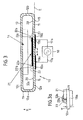
- the device 10 is according to Fig. 3 is shown in a schematic cross-sectional view and comprises a wall 11 with a bottom part 12a, a ceiling part 12c, a left side part 12d and a right side part 12b.
- the wall 11 defines and defines with its wall parts 12a, 12b, 12c, 12d a receiving chamber 13 for any goods.
- Fig. 3 shows by way of example indicated a rectangular-like Good 14, which rests directly on the ceiling wall 12c.
- the exemplified Good 14 may be secured in this case, for example, on the ceiling wall 12c.
- this good 14 can also rest under consideration of the gravitational force on the top part 12c of the wall 11.
- Fig. 3 on the head, which is irrelevant for the following consideration and explanation
- the receiving chamber 13 is enclosed on all sides. Accordingly belongs to the wall 11 nor a front wall part, not shown.
- the rear wall portion of the wall 11 is in Fig. 3 indicated and is denoted by 12e.
- the wall 11 may be formed of a plastic or any other dielectric material.
- the wall 11 has a constant wall thickness W along its entire circumference. This is not required.
- the wall 11 may be formed of a flexible material or formed relatively stiff. This depends on the intended use of the device 10.
- the wall 11 consists of a relatively stiff material.
- Fig. 3 shows that on the outer side 15 of the wall 11, a first outer electrode 16a and a second outer electrode 16b are attached and fixed. It should be noted that between the two electrodes 16a, 16b and the outer side 15 of the wall 11 no air gap remains, but that the two electrodes 16a, 16b are mounted directly on the outer side 15 of the wall 11.
- the two electrodes 16a, 16b are supplied via associated connection lines 17a, 17b of a voltage supply unit 18 with alternating voltage of a suitable frequency and a suitable voltage.
- the free ends 19a, 19b of the respective power supply lines 17a, 17b can be detachably brought into electrical contact with the corresponding electrode 16a, 16b.
- an inner electrode 21 is attached on the inner side 20 of the wall 11, which is opposite to the outer side 15, an inner electrode 21 is attached.
- the inner electrode 21 is attached directly to the inner side 20 of the wall 11 without an air gap remaining between the electrode 21 and the wall 11.
- the device 10 is thus as a transport device or storage device for goods 14th suitable. If required, it can be connected to the connection lines 17a, 17b of a power supply unit 18 when required and when the goods 14 located within the receiving chamber 13 are to be processed.
- an electrical discharge forms along the edges 22a, 22b of the inner electrode 21, namely a surface discharge, ie a plasma in the manner of a smoldering seam.
- the resulting glowing edge is dotted in Fig. 3 indicated and designated there with 23.
- Fig. 3a in a schematic representation of an enlarged detail of the relative Fig. 3 left edge region of the inner electrode 21 and the outer electrode 16a shows, the glowing edge 23 hatched schematically shown.
- the generated plasma in the manner of a Glimmsaumes along the edges is a filamentary plasma, so no APG plasma, and therefore no glow plasma.
- Ozone and UV radiation are referred to below as the agent.
- This agent can interact with the goods 14 located in the receiving chamber 13 and these items, for example, sterilize, disinfect, sterilize od. Like. Also other types of processing, depending on which goods it is, and depending on the located within the receiving chamber 13 Gas or gas mixtures are possible. Thus, bleaching, oxidizing or other surface modification of the goods 14 located in the receiving chamber 13 is also conceivable.
- the inner electrode 21 is a capacitively coupled counter electrode to the two outer electrodes 16a, 16b.
- the inner electrode 21 is thus not with any outside the receiving chamber 13 arranged power supply lines of a power supply unit connected.
- the inner electrode 21 is completely independent therefrom. In it, a voltage is induced exclusively via the outer electrodes 16a, 16b.
- the position of the electrodes 16a, 16b, 21 relative to each other is clearly predetermined.
- the surface discharge 23 can also be predetermined to a very exact extent.
- the wall thickness w of the wall 11 of the device 10 it is possible to adapt the wall thickness w of the wall 11 of the device 10 to the requirements of the desired surface discharge.
- an existing and unchangeable wall thickness w of the chamber wall 11 can be taken into account by changing the electrode geometry.
- the two outer electrodes 16a, 16b are spaced apart along the plane E by the distance x. The distance x is selected so that a breakdown between electrodes 16a, 16b is prevented. If necessary, between the two electrodes 16a and 16b in Fig. 3 Not shown insulator may be arranged.
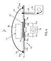
- Fig. 4 shows a second embodiment of the device 10 according to the invention, in which the wall 11 of the device consists of a first wall portion 11a and a second wall portion 11b.
- the first wall portion 11a may be formed, for example, relatively stiff or rigid and provide a kind of support plate.
- the second Wall section 11b may be provided by a more flexible packaging, for example a foil.
- the two wall parts 11a, 11b can be firmly connected to one another in the region of connection regions 24a, 24b, for example by welding, so that a completely closed receiving chamber 13 for goods 14 is provided.
- a good 14 in the form of a rectangle indicated only very schematically.
- the arrangement of the electrodes 16a, 16b and 21 is comparable to the electrode arrangement according to FIG Fig. 3 , so that their description should be omitted here.
- a blower unit 25 which blows into the receiving chamber 13 through a connecting piece 26 and a passage opening 27 in the support plate 11a through air.
- the passage opening 27 is resealable in the manner of a valve, so that after processing the goods 14 a complete gas-tightness or gas impermeability of the device 10 can be achieved.
- Fig. 4 is only to be understood schematically, because due to gravity, the Good 14 almost inevitably rests with material areas on the inner sides of the wall portion 11 a.
- the device can be moved during processing, for example by shaking or shaking, so that it is ensured that in each case different areas of the goods 14 rest on the inner sides of the wall 11, so that also a homogeneous or more homogeneous processing of the goods is possible.
- the fan 25 via the fan 25, the connecting section 26 and the passage opening 27, it is also possible to introduce special gases or gas mixtures, in some cases also other agents, into the receiving chamber 13. This is especially important for surface modifications.
- the ends 19a, 19b of the leads 17a, 17b are released from the outer electrodes 16a, 16b, so that the device 10 is detachably connectable to the power supply unit 18 and constitutes a handleable unit serving as a transport device or receptacle for the goods 14 can.
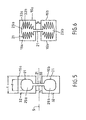
- FIGS. 5 and 6 each show a projection view approximately along the view arrow 5 in Fig. 4 wherein only the inner electrode 21 and the two outer electrodes 16a, 16b are shown. In other words, the wall 11b, the good 14 and the wall portion 11a are omitted for clarity.
- Fig. 5 shows that the inner electrode 21 is substantially dumbbell-shaped and has a first center 29 a and a second center 29 b, which communicate with each other via a narrow connecting web 30 are connected.
- the two outer electrodes 16a, 16b are formed substantially square and spaced from each other by the distance x. Both the inner electrode 21 and the two outer electrodes 16a, 16b are arranged symmetrically along a plane of symmetry S.
- each of the outer electrodes 16a, 16b represents a square of the edge length I.
- Each center 29a, 29b of the inner electrode 21 substantially corresponds to a square with rounded corners, where the square has an edge length Z. Z is smaller than I so that the projected area of each center 29a, 29b is within the contours 32 of an outer electrode 16a, 16b.
- the contour of the inner electrode 21 is designated 31, the contour of the outer electrode 16a, 16b is designated 32.
- a smoldering seam 23 (FIG. Fig. 3 It is important that the length of the mulling seam is substantially proportional to the length of the corresponding peripheral edge 31, 22a, 22b of the inner electrode 21.
- Another embodiment of the inner electrode 21 according to Fig. 6 shows an inner electrode 21 in the manner of a double fir-tree-like or fern leaf-like structure in which the peripheral edge or contour 31 of the inner electrode 21 is provided with a plurality of direction change points 33a, 33b.
- the electrodes may also be serrated or alternatively serpentine.
- the structuring of the electrode contour is important only along a plane E.
- inner electrodes 21 may also have a number of openings beyond.
- each center 29a, 29b of an electrode 21 according to Fig. 5 be provided with a plurality of hole-like openings, so that the edge length of the edge regions is significantly increased. As a result, the ozone generation can be further improved.
- the electrode dimensions can be in the millimeter or centimeter range. The smaller the dimensions of the device 10 in total, the smaller the electrode surfaces can be selected.
- the embodiments of the Figures 3 and 4 refer to both devices 10 having a flexible wall and devices having a substantially rigid wall.
- a flexible device it is therefore conceivable, for example, to form the wall from a flexible plastic bag or pouch which provides an access opening to the receiving chamber 13 via a zipper.
- medical devices easily in the Accommodating chamber 13 are introduced and the receiving chamber are closed by the zipper. Subsequently, the processing of the medical devices, for example in the form of a disinfection, take place.
- the wall 11 may also be formed of relatively rigid material, wherein an access opening for the receiving chamber of a door, a flap, a lid od. Like. Is formed.
- the moisture content within the receiving chamber 13 can be increased, for example, in a simple manner before the closure of the wall 11 and thus before the processing of the goods, by spraying the inside of the wall 11 with steam.
- An increased water vapor content can make ozone generation more efficient.
Landscapes
- Life Sciences & Earth Sciences (AREA)
- Health & Medical Sciences (AREA)
- Engineering & Computer Science (AREA)
- Epidemiology (AREA)
- Veterinary Medicine (AREA)
- Public Health (AREA)
- Chemical & Material Sciences (AREA)
- General Health & Medical Sciences (AREA)
- Animal Behavior & Ethology (AREA)
- Plasma & Fusion (AREA)
- Physics & Mathematics (AREA)
- Zoology (AREA)
- Polymers & Plastics (AREA)
- Food Science & Technology (AREA)
- Wood Science & Technology (AREA)
- Spectroscopy & Molecular Physics (AREA)
- Chemical Kinetics & Catalysis (AREA)
- General Chemical & Material Sciences (AREA)
- Biomedical Technology (AREA)
- Medicinal Chemistry (AREA)
- Molecular Biology (AREA)
- Apparatus For Disinfection Or Sterilisation (AREA)
- Physical Or Chemical Processes And Apparatus (AREA)
- Oxygen, Ozone, And Oxides In General (AREA)
Applications Claiming Priority (2)
| Application Number | Priority Date | Filing Date | Title |
|---|---|---|---|
| DE102004049783A DE102004049783B4 (de) | 2004-10-12 | 2004-10-12 | Vorrichtung zur Bearbeitung von Gütern unter Zuhilfenahme einer elektrischen Entladung |
| PCT/DE2005/001651 WO2006039883A1 (de) | 2004-10-12 | 2005-09-20 | Vorrichtung zur bearbeitung von gütern unter zuhilfenahme einer elektrischen entladung |
Publications (2)
| Publication Number | Publication Date |
|---|---|
| EP1814600A1 EP1814600A1 (de) | 2007-08-08 |
| EP1814600B1 true EP1814600B1 (de) | 2010-12-22 |
Family
ID=35456047
Family Applications (1)
| Application Number | Title | Priority Date | Filing Date |
|---|---|---|---|
| EP05791202A Expired - Lifetime EP1814600B1 (de) | 2004-10-12 | 2005-09-20 | Vorrichtung zur bearbeitung von gütern unter zuhilfenahme einer elektrischen entladung |
Country Status (8)
| Country | Link |
|---|---|
| US (1) | US20080260578A1 (enExample) |
| EP (1) | EP1814600B1 (enExample) |
| JP (1) | JP2008515616A (enExample) |
| KR (1) | KR20070084118A (enExample) |
| CN (1) | CN101039703A (enExample) |
| DE (2) | DE102004049783B4 (enExample) |
| ES (1) | ES2357773T3 (enExample) |
| WO (1) | WO2006039883A1 (enExample) |
Families Citing this family (48)
| Publication number | Priority date | Publication date | Assignee | Title |
|---|---|---|---|---|
| DE102006025736A1 (de) * | 2006-05-31 | 2007-12-06 | RUHR-UNIVERSITäT BOCHUM | Sterilisationsverfahren |
| DE102008045507A1 (de) | 2007-09-11 | 2009-04-02 | Dacor Etiketten Dausend Und Steuernagel Gmbh & Co. Kg | Vorrichtung zur Erzeugung von Ozon und/oder UV-Strahlung |
| WO2009040130A1 (en) * | 2007-09-28 | 2009-04-02 | Danmarks Tekniske Universitet | Method for sterilization of objects |
| US9757487B2 (en) | 2007-11-21 | 2017-09-12 | University Of Florida Research Foundation, Inc. | Self-sterilizing device using plasma fields |
| DE102008037898B4 (de) * | 2008-02-13 | 2022-06-02 | The Coca-Cola Co. | Verfahren und Vorrichtung zur Sterilisation von Verpackungsmaterial und/oder Behältern, diesbezügliche Verwendung von Plasma sowie entsprechend behandeltes Material oder Behälter |
| DE202008008733U1 (de) | 2008-07-02 | 2009-11-19 | Melitta Haushaltsprodukte Gmbh & Co. Kg | Vorrichtung zur Behandlung von Gegenständen |
| DE202008008736U1 (de) | 2008-07-02 | 2009-11-19 | Melitta Haushaltsprodukte Gmbh & Co. Kg | Vorrichtung zur Erzeugung von Plasma mittels elektrischer Entladung |
| DE202008008731U1 (de) | 2008-07-02 | 2009-11-19 | Melitta Haushaltsprodukte Gmbh & Co. Kg | Anordnung zur Herstellung von Plasma |
| DE102008030913B4 (de) * | 2008-07-02 | 2013-03-07 | Reinhausen Plasma Gmbh | Wundschnellverband |
| DE202008008734U1 (de) | 2008-07-02 | 2009-11-19 | Melitta Haushaltsprodukte Gmbh & Co. Kg | Vorrichtung zur elektronischen Behandlung von Gegenständen in einem Folienbeutel und Folienbeutel |
| DE202008008730U1 (de) | 2008-07-02 | 2009-11-19 | Melitta Haushaltsprodukte Gmbh & Co. Kg | Nachrüstsatz für einen Behälter |
| EP2170022A1 (en) * | 2008-09-25 | 2010-03-31 | Max-Planck-Gesellschaft zur Förderung der Wissenschaften e.V. | Plasma applicator and corresponding method |
| US9363880B2 (en) | 2009-03-24 | 2016-06-07 | Purdue Research Foundation | Method and system for treating packaged products |
| WO2012125435A2 (en) | 2011-03-11 | 2012-09-20 | Purdue Research Foundation | Generation of microbiocide inside a package utilizing a controlled gas composition |
| GB0919274D0 (en) | 2009-11-03 | 2009-12-16 | Univ The Glasgow | Plasma generation apparatus and use of plasma generation apparatus |
| TR201001466A1 (tr) * | 2010-02-26 | 2011-09-21 | Al� Topo Mehmet | Katı ve sıvı gıdalar için antibakteriyel özellikli ambalaj üretimi yöntemi ve ambalaj. |
| DE102010003284A1 (de) | 2010-03-25 | 2011-09-29 | Dot Gmbh | Verfahren zur chemischen Aktivierung von Arbeitsgasen in abgeschlossenen Volumina |
| US20110268850A1 (en) * | 2010-04-30 | 2011-11-03 | Vashui Rasanayagam | Modified atmosphere packaging gas, method for non-thermal plasma treatment of article, and article of manufacture for use therein |
| US10507439B2 (en) * | 2010-06-07 | 2019-12-17 | University Of Florida Research Foundation, Inc. | Plasma induced fluid mixing |
| US9056148B2 (en) * | 2010-10-27 | 2015-06-16 | University Of Florida Research Foundation, Inc. | Method and apparatus for disinfecting and/or self-sterilizing a stethoscope using plasma energy |
| DE102012205172B3 (de) * | 2012-03-29 | 2013-04-18 | Leica Biosystems Nussloch Gmbh | Kryostat mit Plasma-Desinfektionsvorrichtung |
| GB2500680B (en) * | 2012-03-29 | 2017-04-19 | Ozonica Ltd | Apparatus and method for disinfection of packaged articles |
| DE102012103777A1 (de) * | 2012-05-22 | 2013-11-28 | Reinhausen Plasma Gmbh | Verfahren und vorrichtung zur beständigkeitsprüfung eines werkstoffs |
| PL2857045T3 (pl) * | 2012-05-28 | 2019-02-28 | Saraya Co., Ltd. | Urządzenie do sterylizacji i sposób sterylizacji przy jego użyciu |
| US9849202B2 (en) * | 2012-09-14 | 2017-12-26 | The Board Of Regents For Oklahoma State University | Plasma pouch |
| DE102013107448B4 (de) | 2013-07-15 | 2016-11-24 | Relyon Plasma Gmbh | Anordnung zur Keimreduktion mittels Plasma |
| NL2013151C2 (en) * | 2013-10-30 | 2015-05-04 | Johannes Adrianus Maria Hoefnagels | Process for the treatment of fruits and vegetables. |
| JP6706203B2 (ja) * | 2013-12-10 | 2020-06-03 | ノバ プラズマ リミテッド | インプラントを扱うための容器、機器、及び方法 |
| DE102013226814A1 (de) | 2013-12-20 | 2015-06-25 | Christof-Herbert Diener | Plasmaanlage mit einem separat transportierbaren Gefäß |
| JP5796641B2 (ja) * | 2014-01-17 | 2015-10-21 | 三菱電機株式会社 | マンコンベア |
| WO2016007000A1 (en) * | 2014-07-08 | 2016-01-14 | Johannes Adrianus Maria Hoefnagels | Process for the treatment of biological material |
| CN104126641B (zh) * | 2014-07-18 | 2015-04-08 | 南京农业大学 | 生鲜肉高压电场等离子体协同纳米光催化杀菌保鲜方法 |
| JP2018511158A (ja) * | 2015-03-11 | 2018-04-19 | プラスモロジー4,インコーポレイティド | 容器処理システム |
| US10978277B2 (en) | 2015-05-11 | 2021-04-13 | Nova Plasma Ltd. | Apparatus and method for handling an implant |
| EP3305330B1 (en) * | 2015-05-27 | 2019-09-11 | Creative Technology Corporation | Sterilizing sheet |
| US10194672B2 (en) | 2015-10-23 | 2019-02-05 | NanoGuard Technologies, LLC | Reactive gas, reactive gas generation system and product treatment using reactive gas |
| DE102015119369A1 (de) | 2015-11-10 | 2017-05-11 | INP Leipniz-Institut für Plalsmaforschung und Technologie e.V. | Vorrichtung, System und Verfahren zur Behandlung eines Gegenstandes mit Plasma |
| KR101845688B1 (ko) * | 2016-02-15 | 2018-04-06 | 주식회사 플라즈맵 | 포장 용기를 이용한 고효율 멸균 장치 |
| KR102571404B1 (ko) * | 2016-05-02 | 2023-08-29 | 서울바이오시스 주식회사 | 임플란트 포장 용기 |
| KR101697242B1 (ko) * | 2016-10-04 | 2017-02-02 | 주식회사 스킨드림 | 화장용 퍼프 살균장치 |
| WO2019035135A1 (en) | 2017-08-16 | 2019-02-21 | Nova Plasma Ltd. | PLASMA PROCESSING OF AN IMPLANT |
| US10925144B2 (en) | 2019-06-14 | 2021-02-16 | NanoGuard Technologies, LLC | Electrode assembly, dielectric barrier discharge system and use thereof |
| DE102020107981A1 (de) | 2020-03-23 | 2021-09-23 | Plasmatreat Gmbh | Vorrichtung zur Desinfektion von Gegenständen oder Feststoffen, vorzugsweise von Schutzausrüstungsteilen, und deren Verwendung |
| KR102441279B1 (ko) * | 2020-03-27 | 2022-09-07 | 연세대학교 산학협력단 | 멸균장치 및 이를 이용한 포장지 내부의 멸균방법 |
| US11896731B2 (en) | 2020-04-03 | 2024-02-13 | NanoGuard Technologies, LLC | Methods of disarming viruses using reactive gas |
| DE102021106664A1 (de) * | 2021-03-18 | 2022-09-22 | Plasmatreat Gmbh | Verfahren und vorrichtung zum desinfizieren, insbesondere sterilisieren, verpackter güter |
| KR20240117876A (ko) * | 2023-01-26 | 2024-08-02 | 주식회사 플라즈맵 | 플라즈마 처리용기, 처리장치 및 방법 |
| WO2024158116A1 (ko) * | 2023-01-26 | 2024-08-02 | 주식회사 플라즈맵 | 플라즈마 처리 시스템 |
Family Cites Families (29)
| Publication number | Priority date | Publication date | Assignee | Title |
|---|---|---|---|---|
| CH442250A (de) * | 1965-07-20 | 1967-08-31 | W Oertli Ag Ing | Elektrode, insbesondere für Ozonisatoren |
| US3719017A (en) * | 1970-10-16 | 1973-03-06 | Pollution Control Ind Inc | Sterilizing and packaging device |
| US4347656A (en) * | 1970-10-29 | 1982-09-07 | Bell Telephone Laboratories, Incorporated | Method of fabricating polysilicon electrodes |
| US4666679A (en) * | 1984-07-18 | 1987-05-19 | Ngk Spark Plug Co., Ltd. | Ceramic ozonizer |
| US4756882A (en) * | 1985-06-21 | 1988-07-12 | Surgikos Inc. | Hydrogen peroxide plasma sterilization system |
| US4643876A (en) * | 1985-06-21 | 1987-02-17 | Surgikos, Inc. | Hydrogen peroxide plasma sterilization system |
| JPH02279160A (ja) * | 1989-03-08 | 1990-11-15 | Abtox Inc | プラズマ滅菌方法及び滅菌装置 |
| GB8907044D0 (en) * | 1989-03-29 | 1989-05-10 | Pin Yu | Movement ozone generator |
| US5169606A (en) * | 1990-06-06 | 1992-12-08 | American Ozone Systems, Inc. | Ozone generator apparatus |
| US5084239A (en) * | 1990-08-31 | 1992-01-28 | Abtox, Inc. | Plasma sterilizing process with pulsed antimicrobial agent treatment |
| GB2259185B (en) * | 1991-08-20 | 1995-08-16 | Bridgestone Corp | Method and apparatus for surface treatment |
| JP3413661B2 (ja) * | 1991-08-20 | 2003-06-03 | 株式会社ブリヂストン | 表面処理方法及びその装置 |
| US5674450A (en) * | 1994-04-28 | 1997-10-07 | Johnson & Johnson Medical, Inc. | Vapor sterilization using a non-aqueous source of hydrogen peroxide |
| US5667753A (en) * | 1994-04-28 | 1997-09-16 | Advanced Sterilization Products | Vapor sterilization using inorganic hydrogen peroxide complexes |
| US5603895B1 (en) * | 1995-06-06 | 1998-11-03 | Abtox Inc | Plasma water vapor sterilizer and method |
| IL115130A (en) * | 1995-09-01 | 1999-09-22 | Israel State | Method and device for ozone sterilization of objects |
| US5868999A (en) * | 1996-03-19 | 1999-02-09 | Ozone Sterilization Products, Inc. | Ozone sterilizer and method for ozone sterilization |
| DE19717160A1 (de) * | 1996-04-23 | 1998-10-29 | Fraunhofer Ges Forschung | Vorrichtung zur Nachbehandlung von Abgas durch Kombination von Gasentladung und Katalysator |
| CZ286541B6 (cs) * | 1998-07-21 | 2000-05-17 | Jiří Rndr. Csc. Dřímal | Zařízení ke generování ozonu |
| US6441553B1 (en) * | 1999-02-01 | 2002-08-27 | Sigma Technologies International, Inc. | Electrode for glow-discharge atmospheric-pressure plasma treatment |
| US7128872B2 (en) * | 1999-04-30 | 2006-10-31 | Tso3 Inc. | Method and apparatus for ozone sterilization |
| DE19931366A1 (de) * | 1999-07-07 | 2001-02-01 | T E M Gmbh | Flache Baugruppe zur elektrischen Erzeugung eines Plasmas in Luft |
| US20030211618A1 (en) * | 2001-05-07 | 2003-11-13 | Patel Gordhandhai Nathalal | Color changing steam sterilization indicator |
| DE10127035A1 (de) * | 2001-06-02 | 2002-02-14 | Dehne Hans Werner | Verfahren zur Entkeimung und Geruchsneutralisation der Luft in Räumen nach dem Prinzip der nichtthermischen, plasma-chemischen Umsetzung bzw. der stillen Grenzschichtentladung arbeitend, wobei erfindungsgemäß die Ozonbildung soweit unterdrückt ist, dass sie unter der Nachweisgrenze von 0.05 ppm liegt. |
| US20030108460A1 (en) * | 2001-12-11 | 2003-06-12 | Andreev Sergey I. | Method for surface corona/ozone making, devices utilizing the same and methods for corona and ozone applications |
| IL147671A0 (en) * | 2002-01-16 | 2002-08-14 | Israel State | An improved ozone chamber for sanitation and sterilization of objects |
| US20040161361A1 (en) * | 2003-02-13 | 2004-08-19 | Uhm Han Sup | Apparatus and method for sterilization of medical equipments, pharmaceutical products and biologically contaminated articles |
| US20050214789A1 (en) * | 2003-04-30 | 2005-09-29 | Moyle William R | Sensors for biomolecular detection and cell classification |
| ATE362648T1 (de) * | 2003-08-14 | 2007-06-15 | Fuji Film Mfg Europ B V | Anordnung, verfahren und elektrode zur erzeugung eines plasmas |
-
2004
- 2004-10-12 DE DE102004049783A patent/DE102004049783B4/de not_active Expired - Fee Related
-
2005
- 2005-09-20 JP JP2007534997A patent/JP2008515616A/ja active Pending
- 2005-09-20 WO PCT/DE2005/001651 patent/WO2006039883A1/de not_active Ceased
- 2005-09-20 ES ES05791202T patent/ES2357773T3/es not_active Expired - Lifetime
- 2005-09-20 KR KR1020077010537A patent/KR20070084118A/ko not_active Ceased
- 2005-09-20 DE DE502005010726T patent/DE502005010726D1/de not_active Expired - Lifetime
- 2005-09-20 US US11/663,926 patent/US20080260578A1/en not_active Abandoned
- 2005-09-20 CN CNA2005800348004A patent/CN101039703A/zh active Pending
- 2005-09-20 EP EP05791202A patent/EP1814600B1/de not_active Expired - Lifetime
Also Published As
| Publication number | Publication date |
|---|---|
| KR20070084118A (ko) | 2007-08-24 |
| WO2006039883A1 (de) | 2006-04-20 |
| DE102004049783B4 (de) | 2009-03-19 |
| JP2008515616A (ja) | 2008-05-15 |
| CN101039703A (zh) | 2007-09-19 |
| DE502005010726D1 (de) | 2011-02-03 |
| US20080260578A1 (en) | 2008-10-23 |
| ES2357773T3 (es) | 2011-04-29 |
| DE102004049783A1 (de) | 2006-04-20 |
| EP1814600A1 (de) | 2007-08-08 |
Similar Documents
| Publication | Publication Date | Title |
|---|---|---|
| EP1814600B1 (de) | Vorrichtung zur bearbeitung von gütern unter zuhilfenahme einer elektrischen entladung | |
| DE69120174T2 (de) | Sterilisation mittels Plasma und gepulster Behandlung mit antimikrobiellen Mitteln | |
| DE69126312T2 (de) | Verfahren zur plasmasterilisation mit zyklen | |
| CN102714912B (zh) | 等离子体发生装置和等离子体发生装置的用途 | |
| EP3092175B1 (de) | Verfahren zur behandlung der offenen schnittkanten von verpackungsmaterial für die fertigung von karton/kunststoffverbundpackungen sowie von verpackungsmaterial | |
| WO2011116984A2 (de) | Verfahren und vorrichtung zur verringerung der keimanzahl in einem abgeschlossenen volumen | |
| DE69632191T2 (de) | Wasserdampfplasmasterilisationsvorrichtung und verfahren. | |
| DE60004975T2 (de) | Verfahren und vorrichtung zur plasmasterilisation | |
| EP3470364B1 (de) | Verfahren zur desinfektion von komponenten einer abfüllanlage und abfüllanlage | |
| DE69834835T2 (de) | Dynamische reduzierung von biologischer beladung durch o(x) | |
| DE102008037898B4 (de) | Verfahren und Vorrichtung zur Sterilisation von Verpackungsmaterial und/oder Behältern, diesbezügliche Verwendung von Plasma sowie entsprechend behandeltes Material oder Behälter | |
| DE10318570B4 (de) | Plasmasterilisationsvorrichtung | |
| DE69530840T2 (de) | Gasgemisch zur erzeugung eines plasmas für eine sterilisierungsvorrichtung und sterilisierungsverfahren | |
| EP2111238B1 (de) | Verfahren und vorrichtung zur sterilisation von behältern aus metall | |
| EP2703012A1 (de) | Vorrichtung und Verfahren zur Desinfektion von Behältern | |
| EP3684430A2 (de) | Verfahren zur reduktion mikrobiologischer kontamination | |
| DE60010693T2 (de) | Verfahren und vorrichtung zur plasmasterilisation bei niedriger temperatur | |
| DE69701363T2 (de) | Verfahren zum behandeln einer oberfläche durch einen trockenprozess und vorrichtung zum ausführen des verfahrens | |
| EP0801952A2 (de) | Vorrichtung zum Sterilisieren der Innenflächen von druck-empfindlichen Behältern | |
| Nur et al. | Ozone production by Dielectric Barrier Discharge Plasma for microbial inactvation in rice | |
| EP3325355B1 (de) | Verfahren zum sterilisieren von verpackten oder teilverpackten bzw. teilweise verschlossenen gebrauchsgütern sowie dazu verwendbare sammelbehälter und umverpackungen | |
| DE60202979T2 (de) | Einstellbarer Speicherbehälter | |
| EP0377799B1 (de) | Verfahren zum Sterilisieren oder Reinigen von Gegenständen | |
| EP0460380B1 (de) | Verfahren und Vorrichtung zum Rundumsterilisieren von gestapelten Verpackungselementen, insbesondere aus Kunststoff bestehende Becher mit unterschiedlichen Wandstärken | |
| DE2556999A1 (de) | Verfahren zur vernichtung von schaedlingen in lagernden guetern und zur entseuchung von gueter aufnehmenden raeumen |
Legal Events
| Date | Code | Title | Description |
|---|---|---|---|
| PUAI | Public reference made under article 153(3) epc to a published international application that has entered the european phase |
Free format text: ORIGINAL CODE: 0009012 |
|
| 17P | Request for examination filed |
Effective date: 20070312 |
|
| AK | Designated contracting states |
Kind code of ref document: A1 Designated state(s): DE ES FR GB IT NL |
|
| 17Q | First examination report despatched |
Effective date: 20070725 |
|
| DAX | Request for extension of the european patent (deleted) | ||
| RBV | Designated contracting states (corrected) |
Designated state(s): DE ES FR GB IT NL |
|
| GRAP | Despatch of communication of intention to grant a patent |
Free format text: ORIGINAL CODE: EPIDOSNIGR1 |
|
| GRAS | Grant fee paid |
Free format text: ORIGINAL CODE: EPIDOSNIGR3 |
|
| GRAA | (expected) grant |
Free format text: ORIGINAL CODE: 0009210 |
|
| AK | Designated contracting states |
Kind code of ref document: B1 Designated state(s): DE ES FR GB IT NL |
|
| REG | Reference to a national code |
Ref country code: GB Ref legal event code: FG4D Free format text: NOT ENGLISH |
|
| REF | Corresponds to: |
Ref document number: 502005010726 Country of ref document: DE Date of ref document: 20110203 Kind code of ref document: P |
|
| REG | Reference to a national code |
Ref country code: DE Ref legal event code: R096 Ref document number: 502005010726 Country of ref document: DE Effective date: 20110203 |
|
| REG | Reference to a national code |
Ref country code: NL Ref legal event code: T3 |
|
| RAP2 | Party data changed (patent owner data changed or rights of a patent transferred) |
Owner name: REINHAUSEN PLASMA GMBH |
|
| REG | Reference to a national code |
Ref country code: NL Ref legal event code: SD Effective date: 20110304 |
|
| REG | Reference to a national code |
Ref country code: ES Ref legal event code: FG2A Ref document number: 2357773 Country of ref document: ES Kind code of ref document: T3 Effective date: 20110429 |
|
| PLBE | No opposition filed within time limit |
Free format text: ORIGINAL CODE: 0009261 |
|
| STAA | Information on the status of an ep patent application or granted ep patent |
Free format text: STATUS: NO OPPOSITION FILED WITHIN TIME LIMIT |
|
| 26N | No opposition filed |
Effective date: 20110923 |
|
| PGFP | Annual fee paid to national office [announced via postgrant information from national office to epo] |
Ref country code: DE Payment date: 20110803 Year of fee payment: 7 |
|
| REG | Reference to a national code |
Ref country code: DE Ref legal event code: R097 Ref document number: 502005010726 Country of ref document: DE Effective date: 20110923 |
|
| PG25 | Lapsed in a contracting state [announced via postgrant information from national office to epo] |
Ref country code: DE Free format text: LAPSE BECAUSE OF NON-PAYMENT OF DUE FEES Effective date: 20130403 |
|
| REG | Reference to a national code |
Ref country code: DE Ref legal event code: R119 Ref document number: 502005010726 Country of ref document: DE Effective date: 20130403 |
|
| PGFP | Annual fee paid to national office [announced via postgrant information from national office to epo] |
Ref country code: GB Payment date: 20140923 Year of fee payment: 10 Ref country code: ES Payment date: 20140923 Year of fee payment: 10 |
|
| PGFP | Annual fee paid to national office [announced via postgrant information from national office to epo] |
Ref country code: IT Payment date: 20140924 Year of fee payment: 10 |
|
| PGFP | Annual fee paid to national office [announced via postgrant information from national office to epo] |
Ref country code: FR Payment date: 20140917 Year of fee payment: 10 |
|
| PGFP | Annual fee paid to national office [announced via postgrant information from national office to epo] |
Ref country code: NL Payment date: 20140922 Year of fee payment: 10 |
|
| PG25 | Lapsed in a contracting state [announced via postgrant information from national office to epo] |
Ref country code: IT Free format text: LAPSE BECAUSE OF NON-PAYMENT OF DUE FEES Effective date: 20150920 |
|
| GBPC | Gb: european patent ceased through non-payment of renewal fee |
Effective date: 20150920 |
|
| REG | Reference to a national code |
Ref country code: NL Ref legal event code: MM Effective date: 20151001 |
|
| REG | Reference to a national code |
Ref country code: FR Ref legal event code: ST Effective date: 20160531 |
|
| PG25 | Lapsed in a contracting state [announced via postgrant information from national office to epo] |
Ref country code: GB Free format text: LAPSE BECAUSE OF NON-PAYMENT OF DUE FEES Effective date: 20150920 |
|
| PG25 | Lapsed in a contracting state [announced via postgrant information from national office to epo] |
Ref country code: FR Free format text: LAPSE BECAUSE OF NON-PAYMENT OF DUE FEES Effective date: 20150930 Ref country code: NL Free format text: LAPSE BECAUSE OF NON-PAYMENT OF DUE FEES Effective date: 20151001 |
|
| REG | Reference to a national code |
Ref country code: ES Ref legal event code: FD2A Effective date: 20161028 |
|
| PG25 | Lapsed in a contracting state [announced via postgrant information from national office to epo] |
Ref country code: ES Free format text: LAPSE BECAUSE OF NON-PAYMENT OF DUE FEES Effective date: 20150921 |