EP1813132B1 - Akustische bandwandleranordnungen - Google Patents
Akustische bandwandleranordnungen Download PDFInfo
- Publication number
- EP1813132B1 EP1813132B1 EP05808347.8A EP05808347A EP1813132B1 EP 1813132 B1 EP1813132 B1 EP 1813132B1 EP 05808347 A EP05808347 A EP 05808347A EP 1813132 B1 EP1813132 B1 EP 1813132B1
- Authority
- EP
- European Patent Office
- Prior art keywords
- ribbon
- flux frame
- microphone
- flux
- frame
- Prior art date
- Legal status (The legal status is an assumption and is not a legal conclusion. Google has not performed a legal analysis and makes no representation as to the accuracy of the status listed.)
- Not-in-force
Links
- 230000004907 flux Effects 0.000 claims description 36
- 239000000463 material Substances 0.000 description 13
- 238000000034 method Methods 0.000 description 13
- 229910052782 aluminium Inorganic materials 0.000 description 8
- XAGFODPZIPBFFR-UHFFFAOYSA-N aluminium Chemical compound [Al] XAGFODPZIPBFFR-UHFFFAOYSA-N 0.000 description 8
- 239000004020 conductor Substances 0.000 description 6
- 238000010276 construction Methods 0.000 description 6
- 239000000835 fiber Substances 0.000 description 5
- 230000006872 improvement Effects 0.000 description 5
- 238000004519 manufacturing process Methods 0.000 description 5
- 229910052751 metal Inorganic materials 0.000 description 5
- 239000002184 metal Substances 0.000 description 5
- 230000004044 response Effects 0.000 description 5
- OKTJSMMVPCPJKN-UHFFFAOYSA-N Carbon Chemical compound [C] OKTJSMMVPCPJKN-UHFFFAOYSA-N 0.000 description 4
- CWYNVVGOOAEACU-UHFFFAOYSA-N Fe2+ Chemical compound [Fe+2] CWYNVVGOOAEACU-UHFFFAOYSA-N 0.000 description 4
- 229910021393 carbon nanotube Inorganic materials 0.000 description 4
- 239000002041 carbon nanotube Substances 0.000 description 4
- 230000008021 deposition Effects 0.000 description 4
- 239000006260 foam Substances 0.000 description 4
- PCHJSUWPFVWCPO-UHFFFAOYSA-N gold Chemical compound [Au] PCHJSUWPFVWCPO-UHFFFAOYSA-N 0.000 description 4
- 239000010931 gold Substances 0.000 description 4
- 229910052737 gold Inorganic materials 0.000 description 4
- 230000008569 process Effects 0.000 description 4
- BQCADISMDOOEFD-UHFFFAOYSA-N Silver Chemical compound [Ag] BQCADISMDOOEFD-UHFFFAOYSA-N 0.000 description 3
- 229910045601 alloy Inorganic materials 0.000 description 3
- 239000000956 alloy Substances 0.000 description 3
- 230000008901 benefit Effects 0.000 description 3
- 230000000712 assembly Effects 0.000 description 2
- 238000000429 assembly Methods 0.000 description 2
- 239000002131 composite material Substances 0.000 description 2
- 230000007423 decrease Effects 0.000 description 2
- 238000005137 deposition process Methods 0.000 description 2
- 238000010586 diagram Methods 0.000 description 2
- 230000000694 effects Effects 0.000 description 2
- 239000012530 fluid Substances 0.000 description 2
- 150000002739 metals Chemical group 0.000 description 2
- 230000035945 sensitivity Effects 0.000 description 2
- 229910052709 silver Inorganic materials 0.000 description 2
- 239000004332 silver Substances 0.000 description 2
- 238000003860 storage Methods 0.000 description 2
- 230000001629 suppression Effects 0.000 description 2
- 239000000725 suspension Substances 0.000 description 2
- 229920000049 Carbon (fiber) Polymers 0.000 description 1
- RYGMFSIKBFXOCR-UHFFFAOYSA-N Copper Chemical compound [Cu] RYGMFSIKBFXOCR-UHFFFAOYSA-N 0.000 description 1
- JOYRKODLDBILNP-UHFFFAOYSA-N Ethyl urethane Chemical compound CCOC(N)=O JOYRKODLDBILNP-UHFFFAOYSA-N 0.000 description 1
- 229920000271 Kevlar® Polymers 0.000 description 1
- 239000004677 Nylon Substances 0.000 description 1
- 238000003070 Statistical process control Methods 0.000 description 1
- 238000002835 absorbance Methods 0.000 description 1
- 239000006096 absorbing agent Substances 0.000 description 1
- 239000011358 absorbing material Substances 0.000 description 1
- 239000000853 adhesive Substances 0.000 description 1
- 230000001070 adhesive effect Effects 0.000 description 1
- 239000004964 aerogel Substances 0.000 description 1
- 230000003321 amplification Effects 0.000 description 1
- 238000005452 bending Methods 0.000 description 1
- 230000015572 biosynthetic process Effects 0.000 description 1
- 230000000903 blocking effect Effects 0.000 description 1
- 239000004917 carbon fiber Substances 0.000 description 1
- 230000008859 change Effects 0.000 description 1
- 238000006243 chemical reaction Methods 0.000 description 1
- HGAZMNJKRQFZKS-UHFFFAOYSA-N chloroethene;ethenyl acetate Chemical compound ClC=C.CC(=O)OC=C HGAZMNJKRQFZKS-UHFFFAOYSA-N 0.000 description 1
- 239000012141 concentrate Substances 0.000 description 1
- 229910052802 copper Inorganic materials 0.000 description 1
- 239000010949 copper Substances 0.000 description 1
- 230000008878 coupling Effects 0.000 description 1
- 238000010168 coupling process Methods 0.000 description 1
- 238000005859 coupling reaction Methods 0.000 description 1
- 230000001066 destructive effect Effects 0.000 description 1
- 238000002059 diagnostic imaging Methods 0.000 description 1
- 230000005520 electrodynamics Effects 0.000 description 1
- 239000002657 fibrous material Substances 0.000 description 1
- 239000010408 film Substances 0.000 description 1
- 230000002452 interceptive effect Effects 0.000 description 1
- 239000004761 kevlar Substances 0.000 description 1
- 230000007774 longterm Effects 0.000 description 1
- 238000003199 nucleic acid amplification method Methods 0.000 description 1
- 229920001778 nylon Polymers 0.000 description 1
- 230000000737 periodic effect Effects 0.000 description 1
- 239000004033 plastic Substances 0.000 description 1
- 238000007747 plating Methods 0.000 description 1
- 230000002787 reinforcement Effects 0.000 description 1
- 238000007665 sagging Methods 0.000 description 1
- 239000004065 semiconductor Substances 0.000 description 1
- 238000007493 shaping process Methods 0.000 description 1
- 229910001281 superconducting alloy Inorganic materials 0.000 description 1
- 230000001360 synchronised effect Effects 0.000 description 1
- 239000010409 thin film Substances 0.000 description 1
- 150000003673 urethanes Chemical class 0.000 description 1
- 238000007740 vapor deposition Methods 0.000 description 1
- 238000005019 vapor deposition process Methods 0.000 description 1
- 230000001755 vocal effect Effects 0.000 description 1
- 238000003466 welding Methods 0.000 description 1
Images


Classifications
-
- H—ELECTRICITY
- H04—ELECTRIC COMMUNICATION TECHNIQUE
- H04R—LOUDSPEAKERS, MICROPHONES, GRAMOPHONE PICK-UPS OR LIKE ACOUSTIC ELECTROMECHANICAL TRANSDUCERS; DEAF-AID SETS; PUBLIC ADDRESS SYSTEMS
- H04R9/00—Transducers of moving-coil, moving-strip, or moving-wire type
- H04R9/02—Details
- H04R9/04—Construction, mounting, or centering of coil
- H04R9/046—Construction
- H04R9/047—Construction in which the windings of the moving coil lay in the same plane
- H04R9/048—Construction in which the windings of the moving coil lay in the same plane of the ribbon type
-
- H—ELECTRICITY
- H04—ELECTRIC COMMUNICATION TECHNIQUE
- H04R—LOUDSPEAKERS, MICROPHONES, GRAMOPHONE PICK-UPS OR LIKE ACOUSTIC ELECTROMECHANICAL TRANSDUCERS; DEAF-AID SETS; PUBLIC ADDRESS SYSTEMS
- H04R1/00—Details of transducers, loudspeakers or microphones
- H04R1/06—Arranging circuit leads; Relieving strain on circuit leads
-
- H—ELECTRICITY
- H04—ELECTRIC COMMUNICATION TECHNIQUE
- H04R—LOUDSPEAKERS, MICROPHONES, GRAMOPHONE PICK-UPS OR LIKE ACOUSTIC ELECTROMECHANICAL TRANSDUCERS; DEAF-AID SETS; PUBLIC ADDRESS SYSTEMS
- H04R1/00—Details of transducers, loudspeakers or microphones
- H04R1/08—Mouthpieces; Microphones; Attachments therefor
-
- H—ELECTRICITY
- H04—ELECTRIC COMMUNICATION TECHNIQUE
- H04R—LOUDSPEAKERS, MICROPHONES, GRAMOPHONE PICK-UPS OR LIKE ACOUSTIC ELECTROMECHANICAL TRANSDUCERS; DEAF-AID SETS; PUBLIC ADDRESS SYSTEMS
- H04R1/00—Details of transducers, loudspeakers or microphones
- H04R1/20—Arrangements for obtaining desired frequency or directional characteristics
- H04R1/32—Arrangements for obtaining desired frequency or directional characteristics for obtaining desired directional characteristic only
- H04R1/34—Arrangements for obtaining desired frequency or directional characteristics for obtaining desired directional characteristic only by using a single transducer with sound reflecting, diffracting, directing or guiding means
- H04R1/342—Arrangements for obtaining desired frequency or directional characteristics for obtaining desired directional characteristic only by using a single transducer with sound reflecting, diffracting, directing or guiding means for microphones
-
- H—ELECTRICITY
- H04—ELECTRIC COMMUNICATION TECHNIQUE
- H04R—LOUDSPEAKERS, MICROPHONES, GRAMOPHONE PICK-UPS OR LIKE ACOUSTIC ELECTROMECHANICAL TRANSDUCERS; DEAF-AID SETS; PUBLIC ADDRESS SYSTEMS
- H04R31/00—Apparatus or processes specially adapted for the manufacture of transducers or diaphragms therefor
- H04R31/003—Apparatus or processes specially adapted for the manufacture of transducers or diaphragms therefor for diaphragms or their outer suspension
-
- H—ELECTRICITY
- H04—ELECTRIC COMMUNICATION TECHNIQUE
- H04R—LOUDSPEAKERS, MICROPHONES, GRAMOPHONE PICK-UPS OR LIKE ACOUSTIC ELECTROMECHANICAL TRANSDUCERS; DEAF-AID SETS; PUBLIC ADDRESS SYSTEMS
- H04R31/00—Apparatus or processes specially adapted for the manufacture of transducers or diaphragms therefor
- H04R31/006—Interconnection of transducer parts
-
- H—ELECTRICITY
- H04—ELECTRIC COMMUNICATION TECHNIQUE
- H04R—LOUDSPEAKERS, MICROPHONES, GRAMOPHONE PICK-UPS OR LIKE ACOUSTIC ELECTROMECHANICAL TRANSDUCERS; DEAF-AID SETS; PUBLIC ADDRESS SYSTEMS
- H04R9/00—Transducers of moving-coil, moving-strip, or moving-wire type
- H04R9/02—Details
- H04R9/025—Magnetic circuit
-
- H—ELECTRICITY
- H04—ELECTRIC COMMUNICATION TECHNIQUE
- H04R—LOUDSPEAKERS, MICROPHONES, GRAMOPHONE PICK-UPS OR LIKE ACOUSTIC ELECTROMECHANICAL TRANSDUCERS; DEAF-AID SETS; PUBLIC ADDRESS SYSTEMS
- H04R1/00—Details of transducers, loudspeakers or microphones
- H04R1/20—Arrangements for obtaining desired frequency or directional characteristics
- H04R1/22—Arrangements for obtaining desired frequency or directional characteristics for obtaining desired frequency characteristic only
- H04R1/28—Transducer mountings or enclosures modified by provision of mechanical or acoustic impedances, e.g. resonator, damping means
- H04R1/2869—Reduction of undesired resonances, i.e. standing waves within enclosure, or of undesired vibrations, i.e. of the enclosure itself
- H04R1/2876—Reduction of undesired resonances, i.e. standing waves within enclosure, or of undesired vibrations, i.e. of the enclosure itself by means of damping material, e.g. as cladding
- H04R1/288—Reduction of undesired resonances, i.e. standing waves within enclosure, or of undesired vibrations, i.e. of the enclosure itself by means of damping material, e.g. as cladding for loudspeaker transducers
-
- H—ELECTRICITY
- H04—ELECTRIC COMMUNICATION TECHNIQUE
- H04R—LOUDSPEAKERS, MICROPHONES, GRAMOPHONE PICK-UPS OR LIKE ACOUSTIC ELECTROMECHANICAL TRANSDUCERS; DEAF-AID SETS; PUBLIC ADDRESS SYSTEMS
- H04R2307/00—Details of diaphragms or cones for electromechanical transducers, their suspension or their manufacture covered by H04R7/00 or H04R31/003, not provided for in any of its subgroups
- H04R2307/023—Diaphragms comprising ceramic-like materials, e.g. pure ceramic, glass, boride, nitride, carbide, mica and carbon materials
-
- H—ELECTRICITY
- H04—ELECTRIC COMMUNICATION TECHNIQUE
- H04R—LOUDSPEAKERS, MICROPHONES, GRAMOPHONE PICK-UPS OR LIKE ACOUSTIC ELECTROMECHANICAL TRANSDUCERS; DEAF-AID SETS; PUBLIC ADDRESS SYSTEMS
- H04R9/00—Transducers of moving-coil, moving-strip, or moving-wire type
- H04R9/08—Microphones
-
- Y—GENERAL TAGGING OF NEW TECHNOLOGICAL DEVELOPMENTS; GENERAL TAGGING OF CROSS-SECTIONAL TECHNOLOGIES SPANNING OVER SEVERAL SECTIONS OF THE IPC; TECHNICAL SUBJECTS COVERED BY FORMER USPC CROSS-REFERENCE ART COLLECTIONS [XRACs] AND DIGESTS
- Y10—TECHNICAL SUBJECTS COVERED BY FORMER USPC
- Y10T—TECHNICAL SUBJECTS COVERED BY FORMER US CLASSIFICATION
- Y10T29/00—Metal working
- Y10T29/49—Method of mechanical manufacture
- Y10T29/49002—Electrical device making
- Y10T29/49005—Acoustic transducer
-
- Y—GENERAL TAGGING OF NEW TECHNOLOGICAL DEVELOPMENTS; GENERAL TAGGING OF CROSS-SECTIONAL TECHNOLOGIES SPANNING OVER SEVERAL SECTIONS OF THE IPC; TECHNICAL SUBJECTS COVERED BY FORMER USPC CROSS-REFERENCE ART COLLECTIONS [XRACs] AND DIGESTS
- Y10—TECHNICAL SUBJECTS COVERED BY FORMER USPC
- Y10T—TECHNICAL SUBJECTS COVERED BY FORMER US CLASSIFICATION
- Y10T29/00—Metal working
- Y10T29/49—Method of mechanical manufacture
- Y10T29/49002—Electrical device making
- Y10T29/4902—Electromagnet, transformer or inductor
- Y10T29/4908—Acoustic transducer
Definitions
- This invention relates to acoustic transducers and more particularly to ribbon and thin film transducers.
- Microphones generally use transducers that are configured either as the electrodynamic type, or more simply "dynamic”, and ribbon, and condenser varieties. Of these three major transducer types used in microphones, the ribbon type is the focus of this invention. Transducers, which may include those utilized for medical imaging, may also be fabricated, used or improved utilizing the principles of the present invention.
- Exemplary prior art ribbon-type transducers are described in WO 99/55118 and WO 01/65890 wherein the outer pole pieces are magnetically connected by bridging elements to concentrate the magnetic field to the slit between the two magnets.
- US6434252B1 discloses a ribbon microphone wherein the ribbon is suspended between two magnets. The ribbon and the two magnets are surrounded by a flux frame.
- US1885001 A discloses a ribbon microphone using two electromagnets. At the location of the ribbon the arms forming part of the magnetic circuit are tapered in order not to block or distort the sound wave.
- Advancement of the microphone art could proceed more quickly if better materials and methods of fabrication could be employed, and if the microphones were assembled and tested using techniques adapted from advanced techniques developed by the semiconductor and medical device industry. Precise positioning of the moving element, closed loop feedback control of the tuning of that element, and statistical process control techniques that reduce piece to piece variability would improve device characteristics and quality and consistency. Close control of microphone characteristics allow artists and studio engineers to quickly arrive and maintain optimal settings for recording, which saves time and production costs by reducing the number of sound checks and retakes required.
- Microphones that are suitable for use on sound stages and in other film and television production settings must be sensitive, robust, and reliable, but not sensitive to positioning or swinging on a boom arm. Such motion may cause wind damage or noise to the delicate ribbon that is suspended within a magnetic gap. Improvements to the strength and durability of that ribbon structure would permit greater application and use of this type of microphone. It would further be desirable to increase the ribbon conductivity, decrease the overall mass and strength of the ribbon without making it excessively stiff, thus improving output efficiency while adding toughness. Output efficiency should be high since that improves the signal to noise ratio and overall sensitivity of the microphone.
- Microphones utilized for recording purposes must be accurate. Each microphone built in a series should ideally perform in an identical manner. This is not always the case with current microphone manufacture inasmuch there are certain variations in the assembly and tuning of such microphones that affect their ability to reproduce sound consistently. It would be desirable to overcome irregularities that produce these variations and have precise assembly and tuning methods that would result in more exact piece-to-piece performance consistency.
- External air currents and wind including airflow from a performer's voice or a musical instrument or an amplified speaker may be of high enough intensity to damage or distort the delicate internal ribbon used in the current art. It would be desirable to permit normal airflow and sounds to freely circulate within the microphone, which then would permit more accurate sound reproduction without attenuation, while at the same time limiting damaging air blasts that exceed a certain intensity level. Such an improvement would allow wider use of the ribbon type microphone.
- the invention thus comprises a ribbonned microphone assembly according to appended claim 1.
- the ribboned microphone assembly includes a transducer having a surrounding flux frame for positioning at least two magnets adjacent a suspended ribbon between said magnets; an array of receiving apertures arranged in the flux frame; and at least one curved return ring positioned in the receiving apertures to create a return path for magnetic flux in the transducer, wherein the flux frame has a first end and a second end and at least one of the first end or the second end comprises a continuous portion of the flux frame.
- the flux frame may have parallel sides.
- the flux frame has outer tapered sides.
- the flux frame preferably has side apertures thereon.
- the side apertures may be non-circular.
- the side apertures may be elongated and curvilinear.
- FIG 1 there is represented a typical prior art ribbon microphone transducer 20, from U.S. Patent 1,885,001 to Olson , shows a corrugated ribbon 22 suspended between ferrous poles 24 extending from an electromagnet 26.
- the electromagnet 26 establishes the magnetic field, which is carried through the pole pieces 24 and into proximity with the sound-responsive ribbon 22.
- an electrical current is generated in the ribbon 22 which may then be amplified, recorded or transmitted.
- a typical prior art ribbon microphone transducer 30 shown in figure 2 as may be seen more completely in U.S.
- Patent 3,435,143 to Fisher illustrates the corrugated ribbon 32 suspended between tapered, ferrous pole pieces 34 extending from a permanent magnet 36.
- the tapered pole pieces 34 reduce the path length between the front of the ribbon and the back of the ribbon, which improves high frequency response.
- the ribbon is suspended in an adjustable frame 38 with screw and nut adjustments that may be used for fine tuning the position of the ribbon 32.
- FIG. 3 wherein a microphone casing 40 is shown having a suspension system 41 consisting of a zig-zag arrangement of elastomeric cords or cables 42, a tapered body shell arrangement 44, and a sound screen 46 having a multiplicity of apertures 48 for sound to propagate through, while preventing ingress of foreign objects, dirt, and the like.
- the cutaway view of figure 4 shows the microphone casing 46 showing a plurality of spaced-apart apertures 48 therethrough, each aperture 48 having an axially curved, non-cylindrical, non-linear shape.
- Figure 5 shows an enlarged view of the apertures 48, representing how air blasts "W” may be directed away from a nearby ribbon “R” under conditions of a high velocity wind.
- Such redirection of strong fluid currents may be attributed to the Coanda effect whereby laminar flow of fluids over curved surfaces is effective to change the direction of flow to conform to those surfaces.
- Apertures 48 shaped with non linear profiles as shown in Figure 5 may allow ordinary vibratory sound waves to enter relatively unimpeded while potentially destructive air blasts are however, directed away from a delicate sound pickup device such as the ribbon 'R", or other transducer.
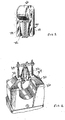
- Figure 6 displays an exploded representation of a modular ribbon microphone assembly 50 comprised of a top ribbon transducer 52, an intermediate matching transformer section 54, and a bottom amplification and electronics control section 56, thus allowing different varieties of ribbon microphone systems to be user-configured.
- Direct interconnecting pins 58 extending from bus bars 57 are used to interconnect each section 52, 54, and 56 to one another.
- Users of microphones often wish to interchange components in the audio chain to adjust different sonic and electronic attributes such as gain, frequency response, timbre, distortion and the like.
- the use of a matched, modular setup has been used in prior art condenser microphones but not in ribbon microphones, because ribbon microphone construction prior to the present invention has not been consistent in gain, frequency response, timbre or distortion.
- Figure 7 represents the assembled stack of transducer, transformer, and electronics modules 52, 54 and 56.
- Straight bus bars 57 are utilized connect the motor to transformer unit, and transformer unit to amplifier/connector unit.
- the straight, preferably in-line fixed position interconnects afford a greater degree of control of hum pickup from external fields, in contrast to circuitous wired connections. Wire connections are often manipulated for lowest hum pickup due to the variable nature of flexible wires.
- the use of rigid interconnecting members 58 virtually eliminates this variable, while at the same time assuring a low resistance, low noise connection.
- the use of silver bars or copper plated with silver provides low resistance and low noise. Thermal noise generated within the conductor is also minimized by the use of thick conductors and silver metal.
- a transducer 60 according to the present invention is shown in figure 8 . It is a tapered transducer 60 featuring a surrounding flux frame 61 that positions two or more adjacent magnets 62 in proximity to an elongated, formed, preferably multilayered, suspended ribbon 66 mounted therebetween.
- the tapered flux frame 61 shortens the acoustic distance from the front to the back of the ribbon 66 to improve high frequency response in the shortened area, and reduces the abruptness of any high frequency cutoff effect that is characteristic of "parallel" sided flux frames.
- the flux frame 61 is equipped with ring-receiving apertures 68 near the position of the magnets 62 extending through the flux frame 61.
- the apertures 68 are positioned to receive curved return rings, (shown for example, as members 72 in figures 9 and 9A ) which are used to create a return path for the magnetic flux.
- curved return rings shown for example, as members 72 in figures 9 and 9A
- This efficiency improvement increases overall output and sensitivity, which is a desirable attribute of high quality microphones.
- the return rings 72 are shaped, with a cross-section that is small with respect to incoming sound waves at any angle. This shape reduces reflections and undesired internal resonance. The overall small cross-section of the return rings 72 reduces blocking or attenuation of the sound energy yet permits sound energy to arrive unhindered at the ribbon 66, while performing flux carrying duty.
- Figures 9 and 9a show a non-tapered, generally parallel-walled transducer 70 with the installed arrangement of return rings 72.
- the return rings 72 may be inserted via press fit into the thickness of the flux frame 73 to enhance coupling of the magnetic field thereto, or they may be attached to the flux frame 73 by welding.
- a further transducer embodiment is shown in Figure 10 with a flux frame 76 having the features of both the tapered and non-tapered styles, having further side apertures 80 to shorten the distance from the front to the back of the ribbon.
- the use of side apertures 80 is known to improve high frequency response in ribbon microphones.
- the use of large, elongated curvilinear/circular side apertures 80 in conjunction with the use of tapered assemblies allows magnetic field strength to be preserved.
- Figure 11a represents a cross section view of a ribbon form 90 having a predetermined ribbon-shaping surface pattern 92.
- the form 90 may be made from a wax or dissolvable material which may support vapor deposition of metals, such as aluminum thereon, or the plating of such metals.
- Figure 11b represents a cross section view of a ribbon form 90 having a deposited layer of aluminum 94.
- the aluminum thickness may generally be from about 1 ⁇ 4 micron to up to about 4 microns. More than one layer (not shown) may be deposited on the surface 92 of the form 90.
- the layers may be of the same materials or of different materials having different mechanical and electrical properties.
- a first layer of gold may be deposited, followed by a second layer of thicker aluminum and then a third gold layer or mixed combinations thereof.
- the gold layers may be very thin, in the order of a few hundred nanometers.
- the aluminum layer may be from 500nm to about 3000nm, more or less, depending upon the size required, the amount of conductivity desired, and the total mass allowed in the design.
- Figure 11c represents, for example, an edge view of a completed ribbon 100 after removal from the form 90.
- the pre-formed metal ribbon 100 is thus stronger and does not have fractures or stresses, nor will it tend to relax.
- Prior art ribbons are made of formed by bending and/or distorting a flat sheet, which compromises the tensile strength and leaves residual forces which may cause the ribbon to relax over time.
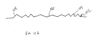
- Figure 11d represents an edge view of a completed ribbon 102 produced by the process of deposition on a form, having a predetermined pattern.
- the pattern may be periodic, aperiodic, or graduated so that smaller, shorter waves portions or undulations 104 are placed near the ends of the ribbon 102, and the flatter portions 106 are arranged near the middle of the ribbon 102. Due to the precise and conformal nature of the deposition process, fine details such as letters (not shown) or features such as longitudinal ribs (not shown) may be produced to mark or stiffen certain planar or surface portions of the ribbon 102.
- Figure 11e shows an example of a graduated fixture 110 having a scale 112, movable slides 114, and clips 116 to hold a ribbon 118 to be adjusted.
- the figure 11f discloses a schematic representation of a tuning system 120 to be utilized with the graduated fixture 110 of figure 11e .
- a variable frequency oscillator 122 may be connected to an amplifier 124 which drives a loudspeaker 126 and triggers a strobe light 128 in synchronization with the oscillator 122.
- the oscillator 122 is set to the desired resonant frequency of the ribbon 118 and the clips 116 are moved until maximum excursion of the ribbon 118 is observed, indicating a resonance peak of the ribbon 118, shown in figure 11e .
- the strobe light 128 aids in the observation of the peak and also any other resonant modes, including out-of-phase modes, which may lead to distortion.
- the ribbon 118 may be precisely tensioned using the combination of the apparatus 110 shown in figure 11e and the apparatus 120 and procedure therewith, represented by figure 11f , and then installed into a transducer assembly when properly tuned.
- the ribbon 118 may then be connected to a load, such as a transformer, and subsequent amplifier, during the tuning process if desired. This fine and precise adjustment of the ribbon 118 improves the unit-to-unit consistency of assemblies which is very desirable.
- the view shown in Figure 12a is a plan view of a series of filaments or fibers 130 suspended between a set of fiber holders 132.
- the fibers 130 may be made of a high tensile strength polymeric material such as Kevlar which does not stretch or shrink.
- the fibers 130 may also be comprised of a carbon nanotube fiber, ribbon or composite having high tensile strength and low mass.
- a carbon nanotube ribbon may be conductive or super-conductive.
- Figure 12b is a side view of the series of filaments 130 shown in figure 12a.
- Figure 12c shows a side view of the series of filaments in proximity to a pair of patterned forms 134 which may apply pressure, heat, or both.
- the view of Figure 12d is a side view of the series of filaments 130 after being impressed with the shape of the forms 134.
- the series of filaments 130 may be further coated, plated or covered using a deposition process, such as a vapor deposition process, not shown for clarity.
- the deposited material may be aluminum or other conductive material such as gold.
- Multiple materials may be used including alloys having superconducting properties. Such alloys are generally stiff and hard to form into wire, yet may be suitably formed in a practical manner by the method described.
- the advantage of using such a superconducting or very highly conducting alloy is an ability to produce a strong, low mass ribbon without reducing the conductivity to the point where microphone output drops to an unacceptable degree.
- Superconducting alloys may have sufficient tensile strength to be used alone in this application.
- Carbon nanotubes or carbon fibers, or ribbons may have sufficient conductivity, strength, and low enough mass, to be used in this application with the advantage of improved toughness, resistance to long term distortion, sagging, or damage.
- Very strong, low mass, and highly conductive ribbons may now be constructed using these new techniques, (such multi-layering done, for example, by bonding, adhesives, deposition or various interactive or adhesion processes).
- FIG 13a there is shown is a top view of a ribbon assembly 140 with a sound absorbing wedge 142 placed a spaced distance from one side, in this case the rear of the ribbon 143.
- the sound absorbing wedge 142 is effective to absorb and attenuate sound energy arriving from the rear of the microphone. Ribbon microphones without sound absorbers exhibit a dipolar, " figure 8 " reception pattern. Monopolar, or unidirectional ribbon operation is sometimes desired.
- the back of the ribbon is sealed so that sound energy does not arrive at the ribbon from the rear.
- the wedge 142 absorbs reradiated sound produced by the moving ribbon.
- the shape of the wedge 142 reduces specular reflection back to the ribbon, which is undesirable. Multiple wedges may be used.
- the wedges may be enclosed to define a chamber 145 having one opening facing the ribbon 143.
- Figure 13b there is shown a detailed view of the sound absorbing wedge 142 showing a heterogeneous structure.
- the heterogeneous structure is comprised of filaments, open cell foams, and closed cell foams 144, each having a directionally-formed increasing density and acoustic impedance to sound, which increase in loss in the form of heat without producing reflections from the front surface, which is at or near the acoustic impedance of air.
- This construction allows lower frequencies to be absorbed at a greater rate than would otherwise be possible with homogeneous materials such as common foams.
- Figure 14 is an example, in a cross section view, of a microphone assembly 150 having "back lobe" suppression.
- An acoustic labyrinth 152 may be produced using rolled or coiled tubing 153 such as plastic tubing, Tygon TM, or other coilable, formable generally tubular materials.
- the formable tubular materials may be arranged in any formation so as to fit within the housing of the microphone 150.
- Back chamber (as described partially in figure 13a ) may be connected to the acoustic labyrinth which may be positioned at or below the transducer assembly 154, or around internal structures or components such as a transformer.
- the tubing 153 may be filled with a lossy, sound absorbing material such as injected, open cell foam of urethane, or filled with a loose, sound absorbing fibrous material such as nylon, or aerogels.
- the length of the tube is generally about 30" (76.2 cm) as described in the prior art for acoustic labyrinth construction using machined ports or chambers which are more difficult to produce and do not offer positioning options of a flexible tube.
- One end of the tube may be attached to the chamber of figure 13a so that a continuous seal of air from the back of the ribbon 143 through the entire length of the tube 153 may be maintained.
- Such an arrangement provides a convenient and repeatable construction of a unidirectional ribbon microphone system which works as a pressure transducer.
- Figure 15a discloses an electrical schematic diagram of a pair of identical ribbons 160 and 162 produced using the teachings herein, arranged in parallel circuit configuration.
- Figure 15b is a top view of the pair of identical ribbons 160 and 162 in proximity to each other and each within gaps of adjacent magnets 164.
- Figure 15c shows a perspective view of a practical holder 166 for the adjacent magnets 164 shown in figure 15b .
- the holder 166 controls the amount of air or sound waves from entering the space between the ribbons (160 and 162) using sliding aperture stops 167 or other adjustable door means.
- the use of two identical ribbons i.e. 160 and 162) allows variable patterns to be produced using ribbon elements within the space of one microphone without excessive distortion due to the identical and repeatable nature of the ribbon elements when produced using improved ribbon and microphone construction methods such as deposition, synchronized tuning, and filamentous or carbon nanotube ribbon construction.
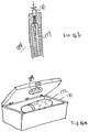
- a storage and travel case 170 is shown in figure 16a , for a pressure sensitive device such as a ribbon microphone 172.
- Prior art boxes generally have a lid which may be closed or opened suddenly. Such sudden unprotected operation as the opening or closing of the case may produce undesired pressures that may damage the contents.
- An air valve 174 is connected to latch (or hinge) so that there is an escape path for air pressure during the opening and closing procedure.
- Figure 16b shows a cross section view of an air escape valve 174.
- a spring loaded plunger 176 may be incorporated into the latch to release air through discharge openings 177 prior to opening.
- the area of the valve 174 is large relative to the case 170 so that undesired pressure cannot build up, even momentarily.
- An exemplary microphone support 180 is shown in Figure 17 in a cross sectional view of a sound absorbing structure integrated into the body of a microphone 182.
- a plurality of annular rings 184 are preferably interposed with acoustically lossy materials 186 such as filled low durometer urethanes.
- the alternating series of lossy segments assures little propagation of noise from the microphone stand 188, up into the microphone head.
- the flat, annular ring arrangement allows reasonably rigid and compact microphone body to be safely maintained while assuring a high area of sound absorbance.
- a clamp 190 may be attached firmly to the microphone body base 191, but is isolated from head, reducing or eliminating sound propagation from the stand into the microphone 182.
Landscapes
- Engineering & Computer Science (AREA)
- Physics & Mathematics (AREA)
- Acoustics & Sound (AREA)
- Signal Processing (AREA)
- Manufacturing & Machinery (AREA)
- Health & Medical Sciences (AREA)
- Otolaryngology (AREA)
- Audible-Bandwidth Dynamoelectric Transducers Other Than Pickups (AREA)
- Diaphragms For Electromechanical Transducers (AREA)
- Laminated Bodies (AREA)
- Details Of Audible-Bandwidth Transducers (AREA)
- Obtaining Desirable Characteristics In Audible-Bandwidth Transducers (AREA)
Claims (4)
- Bebänderte Mikrofonbaugruppe, einen Wandler (60) beinhaltend, Folgendes umfassend:mindestens zwei Magnete (62);ein aufgehängtes Band (66) zwischen den Magneten;einen umgebenden Flussrahmen (61) zum Positionieren der mindestens zwei Magnete angrenzend an das aufhgehängte Band zwischen den Magneten;eine Anordnung von Aufnahmeöffnungen (68), die in dem Flussrahmen angeordnet ist; undmindestens einen gekrümmten Rückführring (72), in den Aufnahmeöffnungen positioniert, um einen Rückführweg für magnetischen Fluss in dem Wandler zu schaffen, wobei jeder gekrümmte Rückführring das aufgehängte Band vollständig einkreist;wobei der umgebende Flussrahmen einen ersten Stangenabschnitt und einen zweiten Stangenabschnitt umfasst, wobei sich jeder von einem ersten Ende des Flussrahmens zu einem zweiten Ende des Flussrahmens erstreckt, wobei der erste und zweite Stangenabschnitt an dem ersten Ende des Flussrahmens durch einen ersten durchgehenden Abschnitt des Flussrahmens und an dem zweiten Ende des Flussrahmens durch einen zweiten durchgehenden Abschnitt des Flussrahmens verbunden ist;wobei der erste Stangenabschnitt, der zweite Stangenabschnitt, der erste durchgehende Abschnitt und der zweite durchgehende Abschnitt ein rechteckiges Loch definieren, das die mindestens zwei Magnete und das aufgehängte Band aufnehmen; undwobei der Flussrahmen spitz zulaufende Außenseiten aufweist, sodass der Flussrahmen durchgehend von einer ersten Breite des ersten Endes des Flussrahmens zu einer zweiten, schmaleren Breite an dem zweiten Ende des Flussrahmens spitz zuläuft.
- Mikrofonbaugruppe nach Anspruch 1, wobei der Flussrahmen Seitenöffnungen darauf aufweist.
- Mikrofonbaugruppe nach Anspruch 2, wobei die Seitenöffnungen nicht kreisförmig sind.
- Mikrofonbaugruppe nach Anspruch 2, wobei die Seitenöffnungen länglich und kurvenförmig sind.
Applications Claiming Priority (2)
| Application Number | Priority Date | Filing Date | Title |
|---|---|---|---|
| US62093404P | 2004-10-21 | 2004-10-21 | |
| PCT/US2005/035702 WO2006047048A2 (en) | 2004-10-21 | 2005-10-03 | Acoustic ribbon transducer arrangements |
Publications (3)
| Publication Number | Publication Date |
|---|---|
| EP1813132A2 EP1813132A2 (de) | 2007-08-01 |
| EP1813132A4 EP1813132A4 (de) | 2011-06-15 |
| EP1813132B1 true EP1813132B1 (de) | 2019-08-14 |
Family
ID=36228203
Family Applications (1)
| Application Number | Title | Priority Date | Filing Date |
|---|---|---|---|
| EP05808347.8A Not-in-force EP1813132B1 (de) | 2004-10-21 | 2005-10-03 | Akustische bandwandleranordnungen |
Country Status (5)
| Country | Link |
|---|---|
| US (4) | US7894619B2 (de) |
| EP (1) | EP1813132B1 (de) |
| JP (2) | JP5094404B2 (de) |
| CN (1) | CN101080944A (de) |
| WO (1) | WO2006047048A2 (de) |
Families Citing this family (26)
| Publication number | Priority date | Publication date | Assignee | Title |
|---|---|---|---|---|
| US6958572B2 (en) * | 2002-02-06 | 2005-10-25 | Ut-Battelle Llc | Controlled non-normal alignment of catalytically grown nanostructures in a large-scale synthesis process |
| JP5094404B2 (ja) * | 2004-10-21 | 2012-12-12 | シュアー インコーポレイテッド | リボン型音響変換器構造 |
| WO2008001190A2 (en) * | 2006-06-26 | 2008-01-03 | Thomas Rogoff Audio (Proprietary) Limited | A ribbon driver and a loudspeaker including a ribbon driver |
| JP2008199336A (ja) * | 2007-02-14 | 2008-08-28 | Audio Technica Corp | リボンマイクロホンユニット、及びリボンマイクロホン |
| JP5038097B2 (ja) * | 2007-11-06 | 2012-10-03 | 株式会社オーディオテクニカ | リボン型マイクロホンおよびリボン型マイクロホンユニット |
| JP5253795B2 (ja) * | 2007-11-29 | 2013-07-31 | 株式会社オーディオテクニカ | リボン型マイクロホンおよびリボン型マイクロホンユニット |
| JP5201578B2 (ja) * | 2008-04-22 | 2013-06-05 | 株式会社オーディオテクニカ | リボンマイクロホン |
| JP5080346B2 (ja) * | 2008-04-24 | 2012-11-21 | 株式会社オーディオテクニカ | リボンマイクロホンユニットおよびリボンマイクロホン |
| US8683798B2 (en) * | 2010-01-15 | 2014-04-01 | Syracuse University | Stimuli-responsive product |
| EP2550812A4 (de) | 2010-03-22 | 2013-10-09 | Aliph Inc | Röhrenkalibrierung für omnidirektionale mikrophone |
| US9084048B1 (en) * | 2010-06-17 | 2015-07-14 | Shindig, Inc. | Audio systems and methods employing an array of transducers optimized for particular sound frequencies |
| WO2012021832A1 (en) | 2010-08-12 | 2012-02-16 | Aliph, Inc. | Calibration system with clamping system |
| JP5485098B2 (ja) * | 2010-10-04 | 2014-05-07 | 株式会社オーディオテクニカ | リボンマイクロホンおよびリボンマイクロホン用収納ケース |
| DE102012208477A1 (de) * | 2012-05-21 | 2013-11-21 | Tesa Se | Asymmetrische Mehrschichtmembran für elektroakustische Wandler |
| WO2015077099A1 (en) * | 2013-11-21 | 2015-05-28 | Ghaffari Mohsen | Tunable ribbon microphone |
| DE102014212768A1 (de) | 2014-07-02 | 2016-01-07 | Robert Bosch Gmbh | Mikromechanische Schallwandleranordnung und ein entsprechendes Herstellungsverfahren |
| KR101610149B1 (ko) * | 2014-11-26 | 2016-04-08 | 현대자동차 주식회사 | 마이크로폰 제조방법, 마이크로폰, 및 그 제어방법 |
| US9877110B2 (en) * | 2014-12-29 | 2018-01-23 | Michael Patrick Timmins | Ribbon support system for electrodynamic microphone |
| US9621996B2 (en) | 2015-07-07 | 2017-04-11 | Robert Bosch Gmbh | Micromechanical sound transducer system and a corresponding manufacturing method |
| US10573291B2 (en) | 2016-12-09 | 2020-02-25 | The Research Foundation For The State University Of New York | Acoustic metamaterial |
| SG11201906197RA (en) * | 2016-12-09 | 2019-08-27 | Univ New York State Res Found | Fiber microphone |
| CN106507265B (zh) * | 2017-01-10 | 2022-08-19 | 天键电声股份有限公司 | 耳机喇叭面盖贴网治具及耳机喇叭面盖自动贴网设备 |
| JP2018133625A (ja) * | 2017-02-13 | 2018-08-23 | ヤマハファインテック株式会社 | 熱音響装置及び音波検査装置 |
| US20190103547A1 (en) * | 2017-09-29 | 2019-04-04 | Olympus Scientific Solutions Americas Inc. | Ultrasonic transducer using aerogel as filler material |
| US10991381B2 (en) * | 2018-04-09 | 2021-04-27 | Well Checked Systems International LLC | System and method for machine learning predictive maintenance through auditory detection on natural gas compressors |
| DE102020001252A1 (de) | 2020-02-26 | 2021-08-26 | Christian Alexander Groneberg | Lautsprechermembran und Verfahren zur Herstellung einer Lautsprechermembran für einen Lautsprecher des Typs Bändchenmagnetostat |
Citations (2)
| Publication number | Priority date | Publication date | Assignee | Title |
|---|---|---|---|---|
| US2699474A (en) * | 1950-12-29 | 1955-01-11 | Rca Corp | Velocity microphone |
| US6434252B1 (en) * | 1999-09-20 | 2002-08-13 | Royer Labs | Ribbon microphone |
Family Cites Families (74)
| Publication number | Priority date | Publication date | Assignee | Title |
|---|---|---|---|---|
| BE396402A (de) | 1931-03-31 | |||
| US2173219A (en) | 1937-05-29 | 1939-09-19 | Rca Corp | Electroacoustical apparatus |
| US2230104A (en) | 1938-12-20 | 1941-01-28 | Bell Telephone Labor Inc | Acoustic device |
| US2361656A (en) | 1941-02-18 | 1944-10-31 | Rediffusion Ltd | Microphone device |
| US2305599A (en) | 1941-04-08 | 1942-12-22 | S N Shure | Conversion of wave motion into electrical energy |
| US2539671A (en) | 1946-02-28 | 1951-01-30 | Rca Corp | Directional microphone |
| US2527344A (en) | 1947-01-30 | 1950-10-24 | Rca Corp | Pressure gradient responsive microphone |
| US2673251A (en) | 1948-06-26 | 1954-03-23 | Rca Corp | Means for preventing infiltration of magnetic dirt particles into the air gap between poles of microphone magnetic structures |
| US2963557A (en) | 1954-06-01 | 1960-12-06 | Rca Corp | Magnetic structure |
| US3435143A (en) | 1965-08-02 | 1969-03-25 | Charles P Fisher | Ribbon microphone |
| US3564163A (en) * | 1967-04-20 | 1971-02-16 | Robert L Wathams | Ribbon loudspeaker |
| US3619517A (en) | 1968-12-23 | 1971-11-09 | Rca Corp | Labyrinth for unidirectional microphone |
| JPS533644B2 (de) * | 1972-01-24 | 1978-02-08 | ||
| JPS5216803Y2 (de) * | 1972-02-26 | 1977-04-15 | ||
| US3832499A (en) * | 1973-01-08 | 1974-08-27 | O Heil | Electro-acoustic transducer |
| JPS5326967B2 (de) * | 1973-10-22 | 1978-08-05 | ||
| JPS50106616A (de) * | 1974-01-10 | 1975-08-22 | ||
| JPS5128725U (de) * | 1974-08-23 | 1976-03-02 | ||
| JPS5140337U (de) * | 1974-09-20 | 1976-03-25 | ||
| SU581599A1 (ru) | 1975-01-14 | 1977-11-25 | Kasatkin Aleksej F | Ленточный громкоговоритель |
| JPS5189411A (de) * | 1975-02-03 | 1976-08-05 | ||
| JPS5527721A (en) | 1978-08-18 | 1980-02-28 | Sony Corp | Diaphragm for electroacoustic converter |
| US4339683A (en) | 1980-02-04 | 1982-07-13 | The United States Of America As Represented By The Secretary Of The Navy | Electrical connection |
| US4460060A (en) | 1980-03-07 | 1984-07-17 | Toray Industries, Inc. | Vibratory diaphragm for loudspeaker |
| US4319096A (en) | 1980-03-13 | 1982-03-09 | Winey James M | Line radiator ribbon loudspeaker |
| JPS56158869A (en) * | 1980-05-09 | 1981-12-07 | Sadami Ito | Method for affixing irregularly reflecting vapor deposition film |
| US4384173A (en) * | 1980-08-01 | 1983-05-17 | Granus Corporation | Electromagnetic planar diaphragm transducer |
| US4395592A (en) | 1981-03-06 | 1983-07-26 | Mark Levinson Audio Systems Ltd. | Ribbon loudspeaker |
| JPS57146496U (de) | 1981-03-10 | 1982-09-14 | ||
| JPS57155373A (en) * | 1981-03-18 | 1982-09-25 | Sadami Ito | Adhering method of irregular reflection evaporated film |
| NL8102572A (nl) | 1981-05-26 | 1982-12-16 | Philips Nv | Elektroakoestische omzetter van het band-type met lage vervorming en verbeterde gevoeligheid. |
| NL8200690A (nl) | 1982-02-22 | 1983-09-16 | Philips Nv | Luidsprekermembraan bevattende een laag van polymethacrylimideschuim. |
| US4473723A (en) * | 1982-06-04 | 1984-09-25 | Hobrough Gilbert L | Ribbon loudspeaker having corregated ribbon for reducing distortion |
| US4580014A (en) * | 1983-06-21 | 1986-04-01 | Hobrough Theodore B | Means for controlling ribbon edge clearance in a ribbon loudspeaker |
| US5021613A (en) | 1985-09-23 | 1991-06-04 | Gold Ribbon Concepts, Inc. | Ribbon loudspeaker |
| US4809578A (en) | 1987-07-14 | 1989-03-07 | Lace Jr Donald A | Magnetic field shaping in an acoustic pick-up assembly |
| US5212736A (en) | 1990-08-08 | 1993-05-18 | Pioneer Electronic Corporation | Ribbon speaker |
| US5206557A (en) * | 1990-11-27 | 1993-04-27 | Mcnc | Microelectromechanical transducer and fabrication method |
| US5195143A (en) | 1991-05-31 | 1993-03-16 | Apogee Acoustics, Inc. | Acoustical ribbon transducer loudspeaker system |
| JPH0568519A (ja) | 1991-09-09 | 1993-03-23 | Mitsubishi Heavy Ind Ltd | 液体加圧用高圧容器の可撓性膜体の検査方法 |
| JPH05140337A (ja) | 1991-11-21 | 1993-06-08 | Teijin Ltd | 成型品母材樹脂用ポリイミド繊維 |
| JPH05189411A (ja) | 1992-01-13 | 1993-07-30 | Nec Corp | 日本語入力システム |
| JPH05216803A (ja) | 1992-02-05 | 1993-08-27 | Nec Eng Ltd | 統合チャネル装置 |
| US5627903A (en) | 1993-10-06 | 1997-05-06 | Chain Reactions, Inc. | Variable geometry electromagnetic transducer |
| US5701359A (en) | 1995-04-06 | 1997-12-23 | Precision Power | Flat-panel speaker |
| US5982905A (en) | 1996-01-22 | 1999-11-09 | Grodinsky; Robert M. | Distortion reduction in signal processors |
| US20050244016A1 (en) | 1997-03-17 | 2005-11-03 | American Technology Corporation | Parametric loudspeaker with electro-acoustical diaphragm transducer |
| US6285769B1 (en) | 1997-04-10 | 2001-09-04 | Borealis Technical Limited | Force balance microphone |
| US6393129B1 (en) | 1998-01-07 | 2002-05-21 | American Technology Corporation | Paper structures for speaker transducers |
| SE9801413L (sv) | 1998-04-22 | 1999-10-23 | Tomas Westermark | Elektroakustisk omvandlare med elektriskt ledande membran |
| US6868166B1 (en) | 1998-06-10 | 2005-03-15 | Xiafu Zhang | Chord-like vibration loudspeaker |
| US20050100181A1 (en) | 1998-09-24 | 2005-05-12 | Particle Measuring Systems, Inc. | Parametric transducer having an emitter film |
| US6535612B1 (en) | 1998-12-07 | 2003-03-18 | American Technology Corporation | Electroacoustic transducer with diaphragm securing structure and method |
| US7174024B1 (en) * | 1999-06-11 | 2007-02-06 | Fps, Inc. | Flat acoustic conversion device |
| WO2001008447A2 (en) | 1999-07-23 | 2001-02-01 | Digital Sonics, Llc | Flat panel speaker |
| EP1216601B1 (de) * | 1999-09-14 | 2003-06-18 | NanoNord A/S | Membranwandler |
| JP3720242B2 (ja) * | 2000-01-17 | 2005-11-24 | 桂子 武藤 | プレーナ型ラウドスピーカー |
| US6834113B1 (en) | 2000-03-03 | 2004-12-21 | Erik Liljehag | Loudspeaker system |
| GR1004325B (el) | 2000-07-03 | 2003-09-05 | Ηλεκτροακουστικος μορφοτροπεας με διαφραγμα που φερει δυο ενδοπλεκομενα πηνια | |
| SE522334C2 (sv) | 2000-09-26 | 2004-02-03 | Bo Bengtsson C O P Glaser | Universell bandelement-modul för två eller flera membranbredder med optimerat flöde och drivning |
| US7136496B2 (en) * | 2001-04-18 | 2006-11-14 | Sonion Nederland B.V. | Electret assembly for a microphone having a backplate with improved charge stability |
| US20030016116A1 (en) | 2001-07-23 | 2003-01-23 | Blaha Charles A. | Method of depositing a thin metallic film and related apparatus |
| EP1318706A1 (de) * | 2001-12-07 | 2003-06-11 | Horst J. Lindemann GmbH | Verfahren und Vorrichtung zur Herstellung von elektrisch leitfähigen Mustern auf Trägern, sowie Folien dazu |
| US6600399B1 (en) | 2002-02-05 | 2003-07-29 | Roland Pierre Trandafir | Transducer motor/generator assembly |
| US7203332B2 (en) | 2002-05-02 | 2007-04-10 | Harman International Industries, Incorporated | Magnet arrangement for loudspeaker |
| US7149321B2 (en) | 2002-05-02 | 2006-12-12 | Harman International Industries, Incorporated | Electro-dynamic loudspeaker mounting system |
| US7278200B2 (en) * | 2002-05-02 | 2007-10-09 | Harman International Industries, Incorporated | Method of tensioning a diaphragm for an electro-dynamic loudspeaker |
| US7203334B2 (en) | 2002-11-22 | 2007-04-10 | Knowles Electronics, Llc. | Apparatus for creating acoustic energy in a balanced receiver assembly and manufacturing method thereof |
| JP4573543B2 (ja) * | 2004-03-02 | 2010-11-04 | 株式会社オーディオテクニカ | 可動リボン型マイクロホン |
| US20060078135A1 (en) * | 2004-10-08 | 2006-04-13 | Royer David E | Ribbon-microphone transducer |
| US20060078152A1 (en) | 2004-10-08 | 2006-04-13 | Royer David E | Ribbon microphone incorporating a special-purpose transformer and/or other transducer-output circuitry |
| JP5094404B2 (ja) * | 2004-10-21 | 2012-12-12 | シュアー インコーポレイテッド | リボン型音響変換器構造 |
| JP4565035B2 (ja) * | 2006-07-04 | 2010-10-20 | 日本ビクター株式会社 | マイクロホン装置 |
| US20080273739A1 (en) | 2007-05-01 | 2008-11-06 | George E. Short Iii | Ribbon transducer with improved excursion and dispersion characteristics |
-
2005
- 2005-10-03 JP JP2007537907A patent/JP5094404B2/ja not_active Expired - Fee Related
- 2005-10-03 WO PCT/US2005/035702 patent/WO2006047048A2/en active Application Filing
- 2005-10-03 CN CNA2005800435322A patent/CN101080944A/zh active Pending
- 2005-10-03 US US11/242,611 patent/US7894619B2/en active Active
- 2005-10-03 EP EP05808347.8A patent/EP1813132B1/de not_active Not-in-force
- 2005-10-03 US US11/242,612 patent/US7900337B2/en active Active
-
2007
- 2007-03-16 US US11/725,137 patent/US8218795B2/en active Active
-
2011
- 2011-03-08 US US13/042,872 patent/US20110158460A1/en not_active Abandoned
- 2011-09-07 JP JP2011194874A patent/JP5417396B2/ja not_active Expired - Fee Related
Patent Citations (2)
| Publication number | Priority date | Publication date | Assignee | Title |
|---|---|---|---|---|
| US2699474A (en) * | 1950-12-29 | 1955-01-11 | Rca Corp | Velocity microphone |
| US6434252B1 (en) * | 1999-09-20 | 2002-08-13 | Royer Labs | Ribbon microphone |
Also Published As
| Publication number | Publication date |
|---|---|
| WO2006047048A2 (en) | 2006-05-04 |
| JP5094404B2 (ja) | 2012-12-12 |
| US20070223773A1 (en) | 2007-09-27 |
| US20080152186A1 (en) | 2008-06-26 |
| EP1813132A4 (de) | 2011-06-15 |
| JP5417396B2 (ja) | 2014-02-12 |
| EP1813132A2 (de) | 2007-08-01 |
| CN101080944A (zh) | 2007-11-28 |
| US7900337B2 (en) | 2011-03-08 |
| US8218795B2 (en) | 2012-07-10 |
| US20110158460A1 (en) | 2011-06-30 |
| JP2008518506A (ja) | 2008-05-29 |
| JP2012023753A (ja) | 2012-02-02 |
| WO2006047048A3 (en) | 2007-02-01 |
| US20070274555A1 (en) | 2007-11-29 |
| US7894619B2 (en) | 2011-02-22 |
Similar Documents
| Publication | Publication Date | Title |
|---|---|---|
| EP1813132B1 (de) | Akustische bandwandleranordnungen | |
| AU2003217250B2 (en) | Low profile audio speaker | |
| EP0493450A1 (de) | Flache lautsprecher | |
| JP2003153357A (ja) | 支持されたエキサイターおよび適合周縁部を備えたフラットパネルサウンドラジエータ | |
| EP1686832B1 (de) | Elektroakusticher Wandler | |
| JPH03503587A (ja) | 制御された柔軟なダイアフラムを備えた改良型オーディオトランスジューサ | |
| US20100034418A1 (en) | High performance micro speaker | |
| US20010033673A1 (en) | Acoustic loudspeaker with energy absorbing bearing and voice coil, and selective sound dampening and dispersion | |
| TW564655B (en) | Flat panel sound radiator with enhanced audio performance | |
| JP5118987B2 (ja) | 単一指向性コンデンサマイクロホンユニットおよびラインマイクロホン | |
| TW515220B (en) | Loudspeakers | |
| KR100638512B1 (ko) | 금속 메쉬 위상지연소자와 이를 구비하는 콘덴서마이크로폰 | |
| US6298140B1 (en) | Electroacoustic transducer with improved tonal quality | |
| US5198624A (en) | Audio transducer with controlled flexibility diaphragm | |
| CN109195087A (zh) | 一种基于热声效应的多层碳纳米管薄膜堆叠式扬声器 | |
| US10880637B2 (en) | Sound output apparatus | |
| CN109314823A (zh) | 用于耳机的宽带电动换能器及相关联的耳机 | |
| Sank | Microphones | |
| US7796768B2 (en) | Variable alignment loudspeaker system | |
| CN104661162B (zh) | 扬声器 | |
| US20070030995A1 (en) | Loudspeaker with natural hair leather diaphragm | |
| Reedyk | Noise‐cancelling electret microphone for lightweight head telephone sets | |
| CA2198734A1 (en) | Electro-acoustic transducer | |
| Watkinson | Transducer drive mechanisms | |
| KR20180012403A (ko) | 평면 음파 반사식 트랜스미션 라인형 인클로우져 스피커 시스템 |
Legal Events
| Date | Code | Title | Description |
|---|---|---|---|
| PUAI | Public reference made under article 153(3) epc to a published international application that has entered the european phase |
Free format text: ORIGINAL CODE: 0009012 |
|
| 17P | Request for examination filed |
Effective date: 20070503 |
|
| AK | Designated contracting states |
Kind code of ref document: A2 Designated state(s): AT BE BG CH CY CZ DE DK EE ES FI FR GB GR HU IE IS IT LI LT LU LV MC NL PL PT RO SE SI SK TR |
|
| AX | Request for extension of the european patent |
Extension state: AL BA HR MK YU |
|
| DAX | Request for extension of the european patent (deleted) | ||
| RAP1 | Party data changed (applicant data changed or rights of an application transferred) |
Owner name: SHURE INCORPORATED |
|
| RIN1 | Information on inventor provided before grant (corrected) |
Inventor name: CROWLEY, ROBERT J. |
|
| A4 | Supplementary search report drawn up and despatched |
Effective date: 20110513 |
|
| RIC1 | Information provided on ipc code assigned before grant |
Ipc: H04R 9/02 20060101ALI20110509BHEP Ipc: H03J 1/00 20060101ALI20110509BHEP Ipc: H04R 31/00 20060101ALI20110509BHEP Ipc: H04R 9/04 20060101ALI20110509BHEP Ipc: H04R 1/34 20060101ALI20110509BHEP Ipc: H04R 1/06 20060101ALI20110509BHEP Ipc: H04R 1/08 20060101ALI20110509BHEP Ipc: H04R 25/00 20060101AFI20070604BHEP |
|
| 17Q | First examination report despatched |
Effective date: 20150915 |
|
| GRAP | Despatch of communication of intention to grant a patent |
Free format text: ORIGINAL CODE: EPIDOSNIGR1 |
|
| STAA | Information on the status of an ep patent application or granted ep patent |
Free format text: STATUS: GRANT OF PATENT IS INTENDED |
|
| INTG | Intention to grant announced |
Effective date: 20190108 |
|
| RIN1 | Information on inventor provided before grant (corrected) |
Inventor name: CROWLEY, ROBERT J. |
|
| INTG | Intention to grant announced |
Effective date: 20190108 |
|
| GRAS | Grant fee paid |
Free format text: ORIGINAL CODE: EPIDOSNIGR3 |
|
| GRAA | (expected) grant |
Free format text: ORIGINAL CODE: 0009210 |
|
| STAA | Information on the status of an ep patent application or granted ep patent |
Free format text: STATUS: THE PATENT HAS BEEN GRANTED |
|
| AK | Designated contracting states |
Kind code of ref document: B1 Designated state(s): AT BE BG CH CY CZ DE DK EE ES FI FR GB GR HU IE IS IT LI LT LU LV MC NL PL PT RO SE SI SK TR |
|
| REG | Reference to a national code |
Ref country code: GB Ref legal event code: FG4D |
|
| REG | Reference to a national code |
Ref country code: CH Ref legal event code: EP Ref country code: AT Ref legal event code: REF Ref document number: 1168467 Country of ref document: AT Kind code of ref document: T Effective date: 20190815 |
|
| REG | Reference to a national code |
Ref country code: IE Ref legal event code: FG4D |
|
| REG | Reference to a national code |
Ref country code: DE Ref legal event code: R096 Ref document number: 602005056155 Country of ref document: DE |
|
| REG | Reference to a national code |
Ref country code: NL Ref legal event code: MP Effective date: 20190814 |
|
| REG | Reference to a national code |
Ref country code: LT Ref legal event code: MG4D |
|
| PG25 | Lapsed in a contracting state [announced via postgrant information from national office to epo] |
Ref country code: PT Free format text: LAPSE BECAUSE OF FAILURE TO SUBMIT A TRANSLATION OF THE DESCRIPTION OR TO PAY THE FEE WITHIN THE PRESCRIBED TIME-LIMIT Effective date: 20191216 Ref country code: FI Free format text: LAPSE BECAUSE OF FAILURE TO SUBMIT A TRANSLATION OF THE DESCRIPTION OR TO PAY THE FEE WITHIN THE PRESCRIBED TIME-LIMIT Effective date: 20190814 Ref country code: NL Free format text: LAPSE BECAUSE OF FAILURE TO SUBMIT A TRANSLATION OF THE DESCRIPTION OR TO PAY THE FEE WITHIN THE PRESCRIBED TIME-LIMIT Effective date: 20190814 Ref country code: SE Free format text: LAPSE BECAUSE OF FAILURE TO SUBMIT A TRANSLATION OF THE DESCRIPTION OR TO PAY THE FEE WITHIN THE PRESCRIBED TIME-LIMIT Effective date: 20190814 Ref country code: LT Free format text: LAPSE BECAUSE OF FAILURE TO SUBMIT A TRANSLATION OF THE DESCRIPTION OR TO PAY THE FEE WITHIN THE PRESCRIBED TIME-LIMIT Effective date: 20190814 Ref country code: BG Free format text: LAPSE BECAUSE OF FAILURE TO SUBMIT A TRANSLATION OF THE DESCRIPTION OR TO PAY THE FEE WITHIN THE PRESCRIBED TIME-LIMIT Effective date: 20191114 |
|
| REG | Reference to a national code |
Ref country code: AT Ref legal event code: MK05 Ref document number: 1168467 Country of ref document: AT Kind code of ref document: T Effective date: 20190814 |
|
| PG25 | Lapsed in a contracting state [announced via postgrant information from national office to epo] |
Ref country code: LV Free format text: LAPSE BECAUSE OF FAILURE TO SUBMIT A TRANSLATION OF THE DESCRIPTION OR TO PAY THE FEE WITHIN THE PRESCRIBED TIME-LIMIT Effective date: 20190814 Ref country code: GR Free format text: LAPSE BECAUSE OF FAILURE TO SUBMIT A TRANSLATION OF THE DESCRIPTION OR TO PAY THE FEE WITHIN THE PRESCRIBED TIME-LIMIT Effective date: 20191115 Ref country code: ES Free format text: LAPSE BECAUSE OF FAILURE TO SUBMIT A TRANSLATION OF THE DESCRIPTION OR TO PAY THE FEE WITHIN THE PRESCRIBED TIME-LIMIT Effective date: 20190814 Ref country code: IS Free format text: LAPSE BECAUSE OF FAILURE TO SUBMIT A TRANSLATION OF THE DESCRIPTION OR TO PAY THE FEE WITHIN THE PRESCRIBED TIME-LIMIT Effective date: 20191214 |
|
| PG25 | Lapsed in a contracting state [announced via postgrant information from national office to epo] |
Ref country code: TR Free format text: LAPSE BECAUSE OF FAILURE TO SUBMIT A TRANSLATION OF THE DESCRIPTION OR TO PAY THE FEE WITHIN THE PRESCRIBED TIME-LIMIT Effective date: 20190814 |
|
| PG25 | Lapsed in a contracting state [announced via postgrant information from national office to epo] |
Ref country code: RO Free format text: LAPSE BECAUSE OF FAILURE TO SUBMIT A TRANSLATION OF THE DESCRIPTION OR TO PAY THE FEE WITHIN THE PRESCRIBED TIME-LIMIT Effective date: 20190814 Ref country code: PL Free format text: LAPSE BECAUSE OF FAILURE TO SUBMIT A TRANSLATION OF THE DESCRIPTION OR TO PAY THE FEE WITHIN THE PRESCRIBED TIME-LIMIT Effective date: 20190814 Ref country code: EE Free format text: LAPSE BECAUSE OF FAILURE TO SUBMIT A TRANSLATION OF THE DESCRIPTION OR TO PAY THE FEE WITHIN THE PRESCRIBED TIME-LIMIT Effective date: 20190814 Ref country code: AT Free format text: LAPSE BECAUSE OF FAILURE TO SUBMIT A TRANSLATION OF THE DESCRIPTION OR TO PAY THE FEE WITHIN THE PRESCRIBED TIME-LIMIT Effective date: 20190814 Ref country code: IT Free format text: LAPSE BECAUSE OF FAILURE TO SUBMIT A TRANSLATION OF THE DESCRIPTION OR TO PAY THE FEE WITHIN THE PRESCRIBED TIME-LIMIT Effective date: 20190814 Ref country code: DK Free format text: LAPSE BECAUSE OF FAILURE TO SUBMIT A TRANSLATION OF THE DESCRIPTION OR TO PAY THE FEE WITHIN THE PRESCRIBED TIME-LIMIT Effective date: 20190814 |
|
| PG25 | Lapsed in a contracting state [announced via postgrant information from national office to epo] |
Ref country code: CZ Free format text: LAPSE BECAUSE OF FAILURE TO SUBMIT A TRANSLATION OF THE DESCRIPTION OR TO PAY THE FEE WITHIN THE PRESCRIBED TIME-LIMIT Effective date: 20190814 Ref country code: IS Free format text: LAPSE BECAUSE OF FAILURE TO SUBMIT A TRANSLATION OF THE DESCRIPTION OR TO PAY THE FEE WITHIN THE PRESCRIBED TIME-LIMIT Effective date: 20200224 Ref country code: MC Free format text: LAPSE BECAUSE OF FAILURE TO SUBMIT A TRANSLATION OF THE DESCRIPTION OR TO PAY THE FEE WITHIN THE PRESCRIBED TIME-LIMIT Effective date: 20190814 Ref country code: SK Free format text: LAPSE BECAUSE OF FAILURE TO SUBMIT A TRANSLATION OF THE DESCRIPTION OR TO PAY THE FEE WITHIN THE PRESCRIBED TIME-LIMIT Effective date: 20190814 |
|
| REG | Reference to a national code |
Ref country code: CH Ref legal event code: PL |
|
| REG | Reference to a national code |
Ref country code: DE Ref legal event code: R097 Ref document number: 602005056155 Country of ref document: DE |
|
| PLBE | No opposition filed within time limit |
Free format text: ORIGINAL CODE: 0009261 |
|
| STAA | Information on the status of an ep patent application or granted ep patent |
Free format text: STATUS: NO OPPOSITION FILED WITHIN TIME LIMIT |
|
| PG2D | Information on lapse in contracting state deleted |
Ref country code: IS |
|
| PG25 | Lapsed in a contracting state [announced via postgrant information from national office to epo] |
Ref country code: LU Free format text: LAPSE BECAUSE OF NON-PAYMENT OF DUE FEES Effective date: 20191003 Ref country code: CH Free format text: LAPSE BECAUSE OF NON-PAYMENT OF DUE FEES Effective date: 20191031 Ref country code: LI Free format text: LAPSE BECAUSE OF NON-PAYMENT OF DUE FEES Effective date: 20191031 |
|
| 26N | No opposition filed |
Effective date: 20200603 |
|
| REG | Reference to a national code |
Ref country code: BE Ref legal event code: MM Effective date: 20191031 |
|
| PG25 | Lapsed in a contracting state [announced via postgrant information from national office to epo] |
Ref country code: BE Free format text: LAPSE BECAUSE OF NON-PAYMENT OF DUE FEES Effective date: 20191031 Ref country code: SI Free format text: LAPSE BECAUSE OF FAILURE TO SUBMIT A TRANSLATION OF THE DESCRIPTION OR TO PAY THE FEE WITHIN THE PRESCRIBED TIME-LIMIT Effective date: 20190814 |
|
| PG25 | Lapsed in a contracting state [announced via postgrant information from national office to epo] |
Ref country code: IE Free format text: LAPSE BECAUSE OF NON-PAYMENT OF DUE FEES Effective date: 20191003 |
|
| PG25 | Lapsed in a contracting state [announced via postgrant information from national office to epo] |
Ref country code: CY Free format text: LAPSE BECAUSE OF FAILURE TO SUBMIT A TRANSLATION OF THE DESCRIPTION OR TO PAY THE FEE WITHIN THE PRESCRIBED TIME-LIMIT Effective date: 20190814 |
|
| PG25 | Lapsed in a contracting state [announced via postgrant information from national office to epo] |
Ref country code: HU Free format text: LAPSE BECAUSE OF FAILURE TO SUBMIT A TRANSLATION OF THE DESCRIPTION OR TO PAY THE FEE WITHIN THE PRESCRIBED TIME-LIMIT; INVALID AB INITIO Effective date: 20051003 |
|
| PGFP | Annual fee paid to national office [announced via postgrant information from national office to epo] |
Ref country code: DE Payment date: 20211027 Year of fee payment: 17 Ref country code: GB Payment date: 20211027 Year of fee payment: 17 |
|
| PGFP | Annual fee paid to national office [announced via postgrant information from national office to epo] |
Ref country code: FR Payment date: 20211025 Year of fee payment: 17 |
|
| REG | Reference to a national code |
Ref country code: DE Ref legal event code: R119 Ref document number: 602005056155 Country of ref document: DE |
|
| GBPC | Gb: european patent ceased through non-payment of renewal fee |
Effective date: 20221003 |
|
| PG25 | Lapsed in a contracting state [announced via postgrant information from national office to epo] |
Ref country code: FR Free format text: LAPSE BECAUSE OF NON-PAYMENT OF DUE FEES Effective date: 20221031 Ref country code: DE Free format text: LAPSE BECAUSE OF NON-PAYMENT OF DUE FEES Effective date: 20230503 |
|
| PG25 | Lapsed in a contracting state [announced via postgrant information from national office to epo] |
Ref country code: GB Free format text: LAPSE BECAUSE OF NON-PAYMENT OF DUE FEES Effective date: 20221003 |