EP1811626A1 - Elektrische Durchführung - Google Patents
Elektrische Durchführung Download PDFInfo
- Publication number
- EP1811626A1 EP1811626A1 EP06290159A EP06290159A EP1811626A1 EP 1811626 A1 EP1811626 A1 EP 1811626A1 EP 06290159 A EP06290159 A EP 06290159A EP 06290159 A EP06290159 A EP 06290159A EP 1811626 A1 EP1811626 A1 EP 1811626A1
- Authority
- EP
- European Patent Office
- Prior art keywords
- insulating layer
- conductor
- intermediate layer
- electrical
- layer
- Prior art date
- Legal status (The legal status is an assumption and is not a legal conclusion. Google has not performed a legal analysis and makes no representation as to the accuracy of the status listed.)
- Granted
Links
- 239000004020 conductor Substances 0.000 claims abstract description 30
- 239000000463 material Substances 0.000 claims description 11
- 239000007788 liquid Substances 0.000 claims description 5
- OKTJSMMVPCPJKN-UHFFFAOYSA-N Carbon Chemical compound [C] OKTJSMMVPCPJKN-UHFFFAOYSA-N 0.000 claims description 4
- 239000010439 graphite Substances 0.000 claims description 4
- 229910002804 graphite Inorganic materials 0.000 claims description 4
- -1 polytetrafluoroethylene Polymers 0.000 claims description 4
- 239000002480 mineral oil Substances 0.000 claims description 3
- 239000011521 glass Substances 0.000 claims description 2
- 239000010445 mica Substances 0.000 claims description 2
- 229910052618 mica group Inorganic materials 0.000 claims description 2
- 235000010446 mineral oil Nutrition 0.000 claims description 2
- 238000004804 winding Methods 0.000 claims description 2
- 229920001343 polytetrafluoroethylene Polymers 0.000 claims 1
- 239000004810 polytetrafluoroethylene Substances 0.000 claims 1
- 239000007787 solid Substances 0.000 description 6
- IJGRMHOSHXDMSA-UHFFFAOYSA-N Atomic nitrogen Chemical compound N#N IJGRMHOSHXDMSA-UHFFFAOYSA-N 0.000 description 4
- RYGMFSIKBFXOCR-UHFFFAOYSA-N Copper Chemical compound [Cu] RYGMFSIKBFXOCR-UHFFFAOYSA-N 0.000 description 3
- 229910052802 copper Inorganic materials 0.000 description 3
- 239000010949 copper Substances 0.000 description 3
- 230000000930 thermomechanical effect Effects 0.000 description 3
- 238000000576 coating method Methods 0.000 description 2
- 238000009413 insulation Methods 0.000 description 2
- 239000011344 liquid material Substances 0.000 description 2
- 229910052757 nitrogen Inorganic materials 0.000 description 2
- 238000005192 partition Methods 0.000 description 2
- 239000011343 solid material Substances 0.000 description 2
- 229920000181 Ethylene propylene rubber Polymers 0.000 description 1
- 239000004698 Polyethylene Substances 0.000 description 1
- 239000004743 Polypropylene Substances 0.000 description 1
- 229920005830 Polyurethane Foam Polymers 0.000 description 1
- HCHKCACWOHOZIP-UHFFFAOYSA-N Zinc Chemical compound [Zn] HCHKCACWOHOZIP-UHFFFAOYSA-N 0.000 description 1
- 239000000853 adhesive Substances 0.000 description 1
- 230000001070 adhesive effect Effects 0.000 description 1
- 229910052782 aluminium Inorganic materials 0.000 description 1
- XAGFODPZIPBFFR-UHFFFAOYSA-N aluminium Chemical compound [Al] XAGFODPZIPBFFR-UHFFFAOYSA-N 0.000 description 1
- 239000011248 coating agent Substances 0.000 description 1
- 238000001816 cooling Methods 0.000 description 1
- 239000011243 crosslinked material Substances 0.000 description 1
- 230000006378 damage Effects 0.000 description 1
- 239000003822 epoxy resin Substances 0.000 description 1
- 239000004744 fabric Substances 0.000 description 1
- 239000003365 glass fiber Substances 0.000 description 1
- 238000010438 heat treatment Methods 0.000 description 1
- 239000011810 insulating material Substances 0.000 description 1
- 239000004922 lacquer Substances 0.000 description 1
- 229910052751 metal Inorganic materials 0.000 description 1
- 239000002184 metal Substances 0.000 description 1
- 239000002245 particle Substances 0.000 description 1
- 229920000647 polyepoxide Polymers 0.000 description 1
- 229920000573 polyethylene Polymers 0.000 description 1
- 229920001155 polypropylene Polymers 0.000 description 1
- 239000011496 polyurethane foam Substances 0.000 description 1
- 239000000843 powder Substances 0.000 description 1
- 238000000926 separation method Methods 0.000 description 1
- 239000000126 substance Substances 0.000 description 1
- 239000002887 superconductor Substances 0.000 description 1
- 229920001169 thermoplastic Polymers 0.000 description 1
- 239000012815 thermoplastic material Substances 0.000 description 1
- 239000011345 viscous material Substances 0.000 description 1
- 239000011701 zinc Substances 0.000 description 1
- 229910052725 zinc Inorganic materials 0.000 description 1
Images

Classifications
-
- H—ELECTRICITY
- H02—GENERATION; CONVERSION OR DISTRIBUTION OF ELECTRIC POWER
- H02G—INSTALLATION OF ELECTRIC CABLES OR LINES, OR OF COMBINED OPTICAL AND ELECTRIC CABLES OR LINES
- H02G15/00—Cable fittings
- H02G15/34—Cable fittings for cryogenic cables
-
- A—HUMAN NECESSITIES
- A41—WEARING APPAREL
- A41D—OUTERWEAR; PROTECTIVE GARMENTS; ACCESSORIES
- A41D11/00—Garments for children
-
- A—HUMAN NECESSITIES
- A41—WEARING APPAREL
- A41B—SHIRTS; UNDERWEAR; BABY LINEN; HANDKERCHIEFS
- A41B13/00—Baby linen
-
- A—HUMAN NECESSITIES
- A41—WEARING APPAREL
- A41D—OUTERWEAR; PROTECTIVE GARMENTS; ACCESSORIES
- A41D1/00—Garments
- A41D1/02—Jackets
-
- A—HUMAN NECESSITIES
- A41—WEARING APPAREL
- A41D—OUTERWEAR; PROTECTIVE GARMENTS; ACCESSORIES
- A41D27/00—Details of garments or of their making
- A41D27/10—Sleeves; Armholes
-
- A—HUMAN NECESSITIES
- A41—WEARING APPAREL
- A41D—OUTERWEAR; PROTECTIVE GARMENTS; ACCESSORIES
- A41D27/00—Details of garments or of their making
- A41D27/12—Shields or protectors
- A41D27/13—Under-arm shields
- A41D27/136—Secured by straps
-
- A—HUMAN NECESSITIES
- A41—WEARING APPAREL
- A41D—OUTERWEAR; PROTECTIVE GARMENTS; ACCESSORIES
- A41D2300/00—Details of garments
- A41D2300/30—Closures
- A41D2300/324—Closures using snap fasteners
-
- Y—GENERAL TAGGING OF NEW TECHNOLOGICAL DEVELOPMENTS; GENERAL TAGGING OF CROSS-SECTIONAL TECHNOLOGIES SPANNING OVER SEVERAL SECTIONS OF THE IPC; TECHNICAL SUBJECTS COVERED BY FORMER USPC CROSS-REFERENCE ART COLLECTIONS [XRACs] AND DIGESTS
- Y02—TECHNOLOGIES OR APPLICATIONS FOR MITIGATION OR ADAPTATION AGAINST CLIMATE CHANGE
- Y02E—REDUCTION OF GREENHOUSE GAS [GHG] EMISSIONS, RELATED TO ENERGY GENERATION, TRANSMISSION OR DISTRIBUTION
- Y02E40/00—Technologies for an efficient electrical power generation, transmission or distribution
- Y02E40/60—Superconducting electric elements or equipment; Power systems integrating superconducting elements or equipment
Definitions
- the invention relates to an electrical feedthrough according to the preamble of claim 1.
- An electrical feedthrough is known, which connects the conductor of a Supfaleiterccis mlt an electrical network.
- the conductor of the implementation consists of a copper conductor, which consists of a solid electrically insulating layer z.
- B. ethylene-propylene rubber or similar materials is surrounded.
- the known implementation connects the conductor of a Supraleitorlienss with an electrical network, the implementation of a range of low temperature, for. B. liquid nitrogen, a range of slightly higher temperature (gaseous nitrogen) passes through to an area at ambient temperature to increase the distance between the junction of the conductor of the superconducting cable with the conductor of the implementation and the range at ambient temperature,
- the present invention has for its object to provide an electrical feedthrough, in which a destruction of the insulating layer is avoided by thermo-mechanical stresses.
- the main advantage of the invention is the fact that the non-positive connection between the conductor and the insulating layer is canceled by the intermediate layer, and an unhindered relative movement between the conductor and the insulating layer is made possible.
- the intermediate layer may consist of a solid material or a liquid or viscous material, it is only essential that the intermediate layer ensures a separation between the conductor and the insulating layer of the bushing, at least within a temperature range of about 70 K to ambient temperature.
- FIG. 1 shows an embodiment of an electrical feedthrough 1 for connecting a superconducting cable 2 is shown with an electrical conductor, not shown.
- the connection to the superconducting cable 2 is located in a housing 3, in which a temperature in the range of 70 Kelvin prevails.
- Adjacent to the housing 3 is a further housing 4, which is connected via a flange 5 with the housing 3.
- a partition 6 separates the interiors of the housings 3 and 4 from each other.
- the interior of the housing 4 is preferably z with a solid thermal insulating material.
- B polyurethane foam or a foamed glass material filled.
- housing 4 is still another housing 7, in which ambient temperature prevails.
- the housing 4 is sealed off from the housing 7 by a dense partition 8.
- the temperature prevailing in the housing 4 is between the cryogenic temperature in the housing 3 and the ambient temperature in the housing 7.
- the outer walls of the housing 3 and 4 form a cryostat for a good thermal insulation.
- the bushing 1 has a central conductor 9, which is provided with an insulating layer 10.
- a field control layer 11 is still provided on the insulating layer 10, which extends at least over part of the insulating layer 10.
- a connection 12 for connection to an electrical network.
- the field control layer 11 consists of a layer of zinc or other conductive material adhering to the outer surface of the insulating layer 10.
- the field control layer 11 is preferably applied in the form of a lacquer layer.
- the insulating layer 10 is made of a thermoplastic or crosslinked material based on polyethylene or polypropylene.
- the insulating layer 10 may also consist of epoxy resin.
- the field control layer 11 is connected to a field control cone 13 known in high voltage engineering.
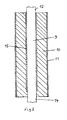
- Fig. 2 the conductor 9 is shown enlarged.
- the ends 12 and 14 protrude from the insulating layer 10.
- the end 12 is connected via an unillustrated cable to the network and the end 14 to the conductor of the superconductor cable.
- an intermediate layer 15 is provided between the conductor 9 and the insulating layer 10, which is intended to allow unimpeded sliding of the conductor 9 in the insulating layer 10. It has been found that when applying the insulating layer 10 on the conductor 9, this glued to the conductor. Because of the different expansion coefficient of the metal for the conductor 9 z. As copper and the material for insulation, it comes when cooling in the operating condition of the Superconducting cable or when heating in the case of switching off the superconducting cable to thermo-mechanical stresses in the insulating layer 10, through which the insulating layer 10 is destroyed. Through the intermediate layer 15, which prevents an adhesive bond between the surface of the conductor 9 and the insulating layer 10, the implementation is fully functional even after repeated Temperoturzyklen.
- Suitable materials for the intermediate layer are solid substances or liquids in question, wherein the liquids in a temperature range of about 70 K to ambient temperature must not be determined.
- liquids mineral oils or polylsobutylene are preferred.
- Solid fabrics may be tape wraps or coatings applied to the conductor 9. Examples of taped tone are paper tape which may also be impregnated or coated with mineral oil, PTFE tape, glass fiber tape, mica tape or similar materials.
- solid coating materials for the conductor 9 graphite or polytetrofluoropolyethylene (PTFE) is preferable.
- materials can be used in which graphite or PTFE powder are present as solid particles.
- combinations of a winding, a liquid and solid materials with sliding properties are possible.
Landscapes
- Engineering & Computer Science (AREA)
- Textile Engineering (AREA)
- Gas Or Oil Filled Cable Accessories (AREA)
- Insulators (AREA)
Abstract
Description
- Die Erfindung betrifft eine elektrische Durchführung nach dem Oberbegriff des Anspruchs 1.
- Aus der
EP 1 283 576 A ist eine elektrische Durchführung bekannt, welche den Leiter eines Supfaleiterkabels mlt einen elektrischen Netz verbindet. Der Leiter der Durchführung besteht aus einem Kupferleiter, der von einer festen elektrisch isolierenden Schicht z. B. Ethylen-Propylen-Kautschuk oder ähnlichen Materialien umgeben ist. - Die bekannte Durchführung verbindet den Leiter eines Supraleitorkabels mit einem elektrischen Netz, wobei die Durchführung einen Bereich tiefer Temperatur, z. B. flüssigem Stickstoff, einen Bereich geringfügig höherer Temperatur (gasförmiger Stickstoff) bis zu einem Bereich bei Umgebungstemperatur durchläuft, um den Abstand zwischen der Verbindungsstelle des Leiters des Supraleiterkabels mit dem Leiter der Durchführung und dem Bereich bei Umgebungstemperatur zu vergrößern,
- Bei dieser Durchführung können Probleme bei Teniperaturänderungen entstehen, wenn z. B, das Supraleiterkabel in oder außer Betrieb genommen wird. Bedingt durch die unterschiedlichen thermischen Ausdehnungskoeffizienten des Leitermaterials der Durchführung (Kupfer, Aluminium etc.) und des Isolierwerkstoffos kommt es zu thermomechanischen Spannungen, welche die Durchführung im Bereich Leitor/Isollerschicht zerstören.
- Der vorliegenden Erfindung liegt die Aufgabe zugrunde, eine elektrische Durchführung bereitzustellen, bei weicher eine Zerstörung der Isolierschicht durch thermomechonische Spannungen vermieden ist.
- Diese Aufgabe wird durch die im Kennzeichen des Anspruchs 1 erfaßten Merkmale gelöst.
- Vorteilhafte Ausgestaltungen der Erfindung sind in den Unteransprüchen und der Beschreibung eines Ausführungsbeispiels der Erfindung beschrieben.
- Der wesentliche Vorteil der Erfindung ist darin zu sehen, daß durch die Zwischenschicht die kraftschlüssige Verbindung zwischen dem Leiter und der Isolierschicht aufgehoben wird, und eine ungehinderte Relativbewegung zwischen dem Leiter und der Isolierschicht ermöglicht wird. Die Zwischenschicht kann aus einem festen Material oder einem flüssigen bzw, viskosen Material bestehen, wesentlich ist nur, daß die Zwischenschicht zumindest innerhalb eines Temperaturbereichs von ca. 70 K bis Umgebungstemperatur eine Trennung zwischen dem Leiter und der Isolierschicht der Durchführung gewährleistet.
- Die Erfindung ist anhand der in den Figuren 1 und 2 schematisch dargestellten Ausführungsbeispiels näher erläutert.
- In der Figur 1 ist ein Ausführungsbeispiel einer elektrischen Durchführung 1 zur Verbindung eines supraleitenden Kabels 2 mit einem nicht dargestellten elektrischen Leiter dargestellt. Die Verbindung an das Supraleitkabel 2 befindet sich in einem Gehäuse 3, in welchem eine Temperatur im Bereich von 70 Kelvin herrscht. Benachbart zu dem Gehäuse 3 befindet sich ein weiteres Gehäuse 4, welches über eine Flanschverbindung 5 mit dem Gehäuse 3 verbunden ist. Eine Trennwand 6 trennt die Innenräume der Gehäuse 3 und 4 voneinander. Der Innenraum des Gehäuses 4 ist vorzugsweise mit einem festen thermischen Isoliermaterial z. B. Polyurethanschaum oder einem geschäumten Glasmaterial ausgefüllt.
- Oberhalb von dem Gehäuse 4 befindet sich noch ein weiteres Gehäuse 7, in welchem umgebungstemperatur herrscht. Das Gehäuse 4 ist gegenüber dem Gehäuse 7 durch eine dichte Trennwand 8 abgeschottet.
- Die in dem Gehäuse 4 herrschende Temperatur liegt zwischen der kryogenen Temperatur im Gehäuse 3 und der Umgebungstemperatur im Gehäuse 7. Die Außenwandungen der Gehäuse 3 und 4 bilden einen Kryostaten für eine gute thermische Isolierung.
- Die Durchführung 1 weist einen zentralen Leiter 9 auf, der mit einer Isolierschicht 10 versehen ist. Darüberhinaus ist noch eine Feldsteuerschicht 11 auf der Isolierschicht 10 vorgesehen, die sich zumindest über einen Teil der Isolierschicht 10 erstreckt. Am oberen Ende der Durchführung Ist ein Anschluß 12 zur Verbindung an ein elektrisches Netz vorhanden.
- Die Feldsteuerschicht 11 besteht aus einer an der äußeren Oberfläche der Isolierschicht 10 anhaftenden Schicht aus Zink oder einem anderen leitfähigen Material. Die Feldsteuerschicht 11 wird vorzugsweise in Form einer Lackschicht aufgebracht. Die Isolierschicht 10 besteht aus einem thermoplastischen oder vernetzten Werkstoff auf der Basis von Polyethylen bzw. Polypropylen. Die Isolierschicht 10 kann aber auch aus Epoxidharz bestehen. Die Feldsteuerschicht 11 ist mit einem in der Hochspannungstechnik bekannten Feldsteuerkonus 13 verbunden.
- In der Fig. 2 ist der Leiter 9 vergrößert dargestellt. Die Enden 12 und 14 ragen aus der Isolierschicht 10 hervor. Das Ende 12 wird über ein nicht dargestelltes Kabel mit dem Netz und das Ende 14 mit dem Leiter des Supraleiterkabels verbunden.
- Gemäß der Lehre der Erfindung ist zwischen dem Leiter 9 und der Isolierschicht 10 eine Zwischenschicht 15 vorgesehen, die ein ungehindertes Gleiten des Leiters 9 in der Isolierschicht 10 ermöglichen soll. Es hat sich nämlich herausgestellt, daß beim Aufbringen der Isolierschicht 10 auf den Leiter 9 diese mit dem Leiter verklebt. Wegen des unterschiedlichen Ausdehnungskoeffizienten des Metalls für den Leiter 9 z. B. Kupfer und dem Material für die Isolierung kommt es beim Abkühlen in den Betriebszustand des Supraleiterkabels bzw. beim Erwörmen im Falle des Abschaltens des Supraleiterkabels zu thermomechanischen Spannungen in der Isolierschicht 10, durch welche die Isolierschicht 10 zerstört wird. Durch die Zwischenschicht 15, die eine klebende Verbindung zwischen der Oberfläche des Leiters 9 und der Isolierschicht 10 unterbindet, ist die Durchführung auch nach mehrmaligen Temperoturzyklen voll funktionsfähig.
- Als Materialien für die Zwischenschicht kommen feste Stoffe oder Flüssigkeiten in Frage, wobei die Flüssigkeiten in einem Temperaturbereich von in etwa 70 K bis Umgebungstemperatur nicht fest werden dürfen. Als Beispiele für Flüssigkeiten werden Mineralöle bzw. auch Polylsobutylen bevorzugt. Feste Stoffe können Bandbewicklungen oder auf den Leiter 9 aufgetragene Beschichtungen sein. Beispiele für Bandbewicktungon sind Papierband, das auch mit Mineralöl getränkt oder beschichtet sein kann, PTFE-Band, Glasseideband, Glimmerband oder ähnliche Materialien. Als feste Beschichtungsmaterialien für den Leiter 9 werden Graphit oder Polytetrofluorpolyethylen (PTFE) bevorzugt. Außerdem können Materialien eingesetzt werden, in denen Graphit oder PTFE-Pulver als feste Partikel befindlich sind. Darüberhinaus sind auch Kombinationen aus einer Bewicklung, einer Flüssigkeit und festen Materialien mit Gleiteigenschaften möglich.
Claims (8)
- Elektrische Durchführung (1) zur Verbindung einer supraleitenden Einrichtung mit einer bei Umgebungstemperatur befindlichen Einrichtung, wobei die Durchführung (1) einen elektrischen Leiter (9) und eine den elektrischen Leiter (9) umgebende Isolierschicht (10) aufweist, dadurch gekennzeichnet, daß zwischen dem elektrischen Leiter (9) und der Isolierschicht (10) eine Zwischenschicht (15) vorgeschen ist, welche ein Gleiten des elektrischen Leiters (9) in der Isolierschicht (10) innerhalb eines Temperaturbereichs von 70 Kelvin bis Umgebungstemperatur ermöglicht.
- Elektrische Durchführung nach Anspruch 1. dadurch gekennzeichnet, daß das Material der Zwischenschicht (15) in dem genannten Temperaturbereich flüssig oder viskos ist.
- Elektrische Durchführung nach Anspruch 2, dadurch gekennzeichnet, daß das Material ein Mineralöl Ist.
- Elektrische Durchführung nach Anspruch 1, dadurch gekennzeichnet, daß die Zwischenschicht (15) aus Polytetrafluorethylen besteht.
- Elektrische Durchführung nach einem der Ansprüche 1 bis 4, dadurch gekennzeichnet, daß die Zwischenschicht (15) eine Bewicklung aus einem hochspannungsfesten Material ist.
- Elektrische Durchführung nach einem der Ansprüche 1 bis 5, dadurch gekennzeichnet, daß die Zwischenschicht (15) aus Graphit besteht.
- Elektrische Durchführung nach einem der Ansprüche 1 bis 6. dadurch gekennzeichnet, daß die Zwischenschicht (15) aus mit Graphit beschichtetem Band besteht.
- Elektrische Durchführung nach einem der Ansprüche 1 bis 7, dadurch gekennzeichnet, daß die Zwischenschicht (15) aus Glimmer- oder Glasseideband bestehl.
Priority Applications (5)
| Application Number | Priority Date | Filing Date | Title |
|---|---|---|---|
| EP06290159.0A EP1811626B1 (de) | 2006-01-24 | 2006-01-24 | Elektrische Durchführung |
| DK06290159.0T DK1811626T3 (en) | 2006-01-24 | 2006-01-24 | Electrical bushing |
| US11/599,168 US7825331B2 (en) | 2006-01-24 | 2006-11-13 | Electrical bushing |
| KR1020070002656A KR101292146B1 (ko) | 2006-01-24 | 2007-01-09 | 전기 부싱 |
| JP2007006741A JP5226951B2 (ja) | 2006-01-24 | 2007-01-16 | 電気ブッシンク゛ |
Applications Claiming Priority (1)
| Application Number | Priority Date | Filing Date | Title |
|---|---|---|---|
| EP06290159.0A EP1811626B1 (de) | 2006-01-24 | 2006-01-24 | Elektrische Durchführung |
Publications (2)
| Publication Number | Publication Date |
|---|---|
| EP1811626A1 true EP1811626A1 (de) | 2007-07-25 |
| EP1811626B1 EP1811626B1 (de) | 2016-04-13 |
Family
ID=36457331
Family Applications (1)
| Application Number | Title | Priority Date | Filing Date |
|---|---|---|---|
| EP06290159.0A Expired - Lifetime EP1811626B1 (de) | 2006-01-24 | 2006-01-24 | Elektrische Durchführung |
Country Status (5)
| Country | Link |
|---|---|
| US (1) | US7825331B2 (de) |
| EP (1) | EP1811626B1 (de) |
| JP (1) | JP5226951B2 (de) |
| KR (1) | KR101292146B1 (de) |
| DK (1) | DK1811626T3 (de) |
Cited By (1)
| Publication number | Priority date | Publication date | Assignee | Title |
|---|---|---|---|---|
| EP2383854A1 (de) | 2010-04-28 | 2011-11-02 | Nexans | Anordnung mit einem supraleitfähigen Kabel |
Families Citing this family (11)
| Publication number | Priority date | Publication date | Assignee | Title |
|---|---|---|---|---|
| DE502005001151D1 (de) * | 2005-12-13 | 2007-09-13 | Nexans S A | Elektrische Durchführung zur Verbindung einer supraleitenden Einrichtung mit einer bei Raumtemperatur befindlichen Einrichtung |
| EP2048673B1 (de) * | 2007-10-12 | 2014-05-14 | ABB Research Ltd. | Vorrichtung für eine elektrische Verbindung, Verfahren zur Herstellung einer solchen Vorrichtung und damit ausgestattete Elektroinstallation |
| EP2053616A1 (de) * | 2007-10-26 | 2009-04-29 | ABB Research Ltd. | Hochspannungs-Freiluftdurchführung |
| EP2584698A4 (de) | 2010-06-21 | 2013-10-16 | Panasonic Corp | Hochfrequenz-verstärkerschaltung |
| EP2431982B1 (de) * | 2010-09-21 | 2014-11-26 | ABB Technology AG | Steckbare Durchführung und Hochspannungsanlage mit einer solchen Durchführung |
| JP5620239B2 (ja) * | 2010-11-30 | 2014-11-05 | 株式会社東芝 | 絶縁支持装置 |
| EP2482290B1 (de) * | 2011-01-28 | 2017-07-19 | ABB Schweiz AG | Temperaturkompensierte Durchführungsanordung |
| US8745819B2 (en) * | 2011-11-18 | 2014-06-10 | The Boeing Company | Load sustaining bushing |
| JP6502674B2 (ja) * | 2014-10-15 | 2019-04-17 | 日本碍子株式会社 | ポリマーブッシング |
| EP3386034B1 (de) * | 2017-04-07 | 2019-04-03 | Nexans | Endverschluss für ein supraleitendes kabel und verfahren zum aufbau eines endverschlusses für ein supraleitendes kabel |
| EP3826035A1 (de) * | 2019-11-20 | 2021-05-26 | ABB Power Grids Switzerland AG | Zugstangenbuchse mit abgedichtetem unterem kontakt |
Citations (5)
| Publication number | Priority date | Publication date | Assignee | Title |
|---|---|---|---|---|
| DE2607516A1 (de) * | 1975-03-07 | 1976-09-09 | Nkf Kabel Bv | Verfahren zur herstellung eines kabels mit mindestens einer kunststoffschicht, die ein mit silan modifiziertes verknuepftes polyolefin enthaelt, und durch dieses verfahren hergestelltes kabel |
| DE2830736B1 (de) * | 1978-07-13 | 1979-12-06 | Kernforschungsz Karlsruhe | Hochspannungskabel |
| JPS5929479A (ja) * | 1982-08-12 | 1984-02-16 | Toshiba Corp | 超電導装置の電流供給端子装置 |
| WO1995028750A1 (en) * | 1994-04-15 | 1995-10-26 | Superconductor Technologies, Inc. | Cryocable |
| EP1283576A1 (de) * | 2001-02-13 | 2003-02-12 | Sumitomo Electric Industries, Ltd. | Verbinderanordnung eines apparats bei ausserst niedriger temperatur |
Family Cites Families (13)
| Publication number | Priority date | Publication date | Assignee | Title |
|---|---|---|---|---|
| US3775547A (en) * | 1972-10-12 | 1973-11-27 | Westinghouse Electric Corp | Cast epoxy bushing having a weldable flange |
| US3783181A (en) * | 1972-10-30 | 1974-01-01 | Westinghouse Electric Corp | Electrical bushing having a stress relieving shield and method of constructing same |
| US4060583A (en) * | 1975-02-28 | 1977-11-29 | Minnesota Mining And Manufacturing Company | Electrically insulating composition |
| JPS5953777B2 (ja) * | 1976-11-17 | 1984-12-26 | 三菱電線工業株式会社 | 極低温ケ−ブル等の端末部 |
| US4401841A (en) * | 1981-01-23 | 1983-08-30 | Meyer Jeffry R | Explosion resistant insulator and method of making same |
| US4500745A (en) * | 1983-03-03 | 1985-02-19 | Interpace Corporation | Hybrid electrical insulator bushing |
| JPS62145608A (ja) * | 1985-12-18 | 1987-06-29 | 株式会社東芝 | モ−ルドブツシング |
| GB8608484D0 (en) * | 1986-04-08 | 1986-05-14 | Raychem Gmbh | Electrical apparatus |
| JPH02237413A (ja) * | 1989-03-08 | 1990-09-20 | Toshiba Corp | 極低温用電流リード |
| JP2584871Y2 (ja) * | 1992-01-31 | 1998-11-11 | 昭和電線電纜株式会社 | ストレスコーン |
| ATE546818T1 (de) * | 2004-03-15 | 2012-03-15 | Abb Research Ltd | Hochspannungsdurchführung mit feldsteuermaterial |
| FR2883427B1 (fr) * | 2005-03-17 | 2007-05-04 | Nexans Sa | Traversee electrique pour element supraconducteur |
| FR2891672B1 (fr) * | 2005-09-30 | 2007-11-23 | Nexans Sa | Dispositif d'alimentation en courant electrique d'un appareil supraconducteur sous moyenne ou haute tension |
-
2006
- 2006-01-24 DK DK06290159.0T patent/DK1811626T3/en active
- 2006-01-24 EP EP06290159.0A patent/EP1811626B1/de not_active Expired - Lifetime
- 2006-11-13 US US11/599,168 patent/US7825331B2/en not_active Expired - Fee Related
-
2007
- 2007-01-09 KR KR1020070002656A patent/KR101292146B1/ko not_active Expired - Fee Related
- 2007-01-16 JP JP2007006741A patent/JP5226951B2/ja not_active Expired - Fee Related
Patent Citations (5)
| Publication number | Priority date | Publication date | Assignee | Title |
|---|---|---|---|---|
| DE2607516A1 (de) * | 1975-03-07 | 1976-09-09 | Nkf Kabel Bv | Verfahren zur herstellung eines kabels mit mindestens einer kunststoffschicht, die ein mit silan modifiziertes verknuepftes polyolefin enthaelt, und durch dieses verfahren hergestelltes kabel |
| DE2830736B1 (de) * | 1978-07-13 | 1979-12-06 | Kernforschungsz Karlsruhe | Hochspannungskabel |
| JPS5929479A (ja) * | 1982-08-12 | 1984-02-16 | Toshiba Corp | 超電導装置の電流供給端子装置 |
| WO1995028750A1 (en) * | 1994-04-15 | 1995-10-26 | Superconductor Technologies, Inc. | Cryocable |
| EP1283576A1 (de) * | 2001-02-13 | 2003-02-12 | Sumitomo Electric Industries, Ltd. | Verbinderanordnung eines apparats bei ausserst niedriger temperatur |
Non-Patent Citations (1)
| Title |
|---|
| PATENT ABSTRACTS OF JAPAN vol. 008, no. 115 (E - 247) 29 May 1984 (1984-05-29) * |
Cited By (2)
| Publication number | Priority date | Publication date | Assignee | Title |
|---|---|---|---|---|
| EP2383854A1 (de) | 2010-04-28 | 2011-11-02 | Nexans | Anordnung mit einem supraleitfähigen Kabel |
| CN102237665A (zh) * | 2010-04-28 | 2011-11-09 | 尼克桑斯公司 | 带有超导性电缆的装置 |
Also Published As
| Publication number | Publication date |
|---|---|
| US7825331B2 (en) | 2010-11-02 |
| JP5226951B2 (ja) | 2013-07-03 |
| EP1811626B1 (de) | 2016-04-13 |
| US20070181324A1 (en) | 2007-08-09 |
| JP2007200882A (ja) | 2007-08-09 |
| DK1811626T3 (en) | 2016-08-01 |
| KR20070077761A (ko) | 2007-07-27 |
| KR101292146B1 (ko) | 2013-08-09 |
Similar Documents
| Publication | Publication Date | Title |
|---|---|---|
| EP2431982B1 (de) | Steckbare Durchführung und Hochspannungsanlage mit einer solchen Durchführung | |
| EP0388689B1 (de) | Axialer elektrischer Wickelkondensator | |
| DE2348895C2 (de) | Verbindung für Starkstromkabel | |
| EP1811626A1 (de) | Elektrische Durchführung | |
| EP2182602A1 (de) | Vorrichtung für eine Verbindungungsstelle zwischen zwei elektrischen Hochspannungskabeln | |
| EP3639282B1 (de) | Steckbare hochspannungsdurchführung und elektrisches gerät mit steckbarer hochspannungsdurchführung | |
| EP2283493B1 (de) | Durchführung mit einem basis-aktivteil und einer isoliereinrichtung | |
| DE4344044A1 (de) | Elektrisches Isoliermaterial und Verfahren zur Herstellung eines elektrisch isolierten Leiters | |
| DE102010018858B4 (de) | Kontaktierungs- und Verbindungsanordnung bestehend aus in einem Gehäuse eingebrachten Folienleitern | |
| EP2418745A1 (de) | Gehäuse zur elektrischen Leitungsverbindung zwischen einem Folienleiter und einem Leiter | |
| EP4049344A1 (de) | Gehäuse, insbesondere leitungsgehäuse, system sowie verfahren zur herstellung eines solchen systems | |
| WO2012163561A1 (de) | Elektrische komponente für eine hochspannungsanlage | |
| DE4007337C2 (de) | Elektrischer Isolator | |
| EP3631821A1 (de) | Steckbare hochspannungsdurchführung und elektrisches gerät mit der steckbaren hochspannungsdurchführung | |
| DE1690498A1 (de) | Einsteckendverschluss fuer abgeschirmte Hochspannungskabel zur Einfuehrung in ein elektrisches Geraet | |
| DE4300177C2 (de) | Verbindungs- und Abzweigmuffe für Koaxialkabel oder dergleichen | |
| DE102018201160A1 (de) | Hochspannungsdurchführung, elektrisches Gerät mit Hochspannungsdurchführung und Verfahren zur Herstellung des elektrischen Gerätes | |
| WO2023138860A1 (de) | Gasisolierte elektroenergieübertragungseinrichtung | |
| DE19856025A1 (de) | Kompakte Übergangsmuffe | |
| EP1796237B1 (de) | Elektrische Durchführung zur Verbindung einer supraleitenden Einrichtung mit einer bei Raumtemperatur befindlichen Einrichtung | |
| DE8432279U1 (de) | Vorrichtung zum Verbinden von Kabeln, insbesondere Koaxialkabeln, wie Breitbandkommunikationskabeln o. dgl. | |
| DE202004007187U1 (de) | Prüfendverschluß für ein supraleitendes Kabel | |
| DE1515453B1 (de) | Flachbahnbuendelleiter als sammelschiene oder kabelbaum | |
| EP2250653B1 (de) | Leiteranschluss an transformatoren | |
| DE20108532U1 (de) | Folienleiter, wie Folienleiterkabel oder -platte |
Legal Events
| Date | Code | Title | Description |
|---|---|---|---|
| PUAI | Public reference made under article 153(3) epc to a published international application that has entered the european phase |
Free format text: ORIGINAL CODE: 0009012 |
|
| AK | Designated contracting states |
Kind code of ref document: A1 Designated state(s): AT BE BG CH CY CZ DE DK EE ES FI FR GB GR HU IE IS IT LI LT LU LV MC NL PL PT RO SE SI SK TR |
|
| AX | Request for extension of the european patent |
Extension state: AL BA HR MK YU |
|
| AKX | Designation fees paid |
Designated state(s): AT BE BG CH CY CZ DE DK EE ES FI FR GB GR HU IE IS IT LI LT LU LV MC NL PL PT RO SE SI SK TR |
|
| 17P | Request for examination filed |
Effective date: 20080313 |
|
| 17Q | First examination report despatched |
Effective date: 20090710 |
|
| RAP1 | Party data changed (applicant data changed or rights of an application transferred) |
Owner name: NEXANS |
|
| GRAP | Despatch of communication of intention to grant a patent |
Free format text: ORIGINAL CODE: EPIDOSNIGR1 |
|
| INTG | Intention to grant announced |
Effective date: 20151029 |
|
| GRAS | Grant fee paid |
Free format text: ORIGINAL CODE: EPIDOSNIGR3 |
|
| GRAA | (expected) grant |
Free format text: ORIGINAL CODE: 0009210 |
|
| AK | Designated contracting states |
Kind code of ref document: B1 Designated state(s): AT BE BG CH CY CZ DE DK EE ES FI FR GB GR HU IE IS IT LI LT LU LV MC NL PL PT RO SE SI SK TR |
|
| REG | Reference to a national code |
Ref country code: GB Ref legal event code: FG4D Free format text: NOT ENGLISH |
|
| REG | Reference to a national code |
Ref country code: AT Ref legal event code: REF Ref document number: 791043 Country of ref document: AT Kind code of ref document: T Effective date: 20160415 Ref country code: CH Ref legal event code: EP |
|
| REG | Reference to a national code |
Ref country code: IE Ref legal event code: FG4D Free format text: LANGUAGE OF EP DOCUMENT: GERMAN |
|
| REG | Reference to a national code |
Ref country code: DE Ref legal event code: R096 Ref document number: 502006014872 Country of ref document: DE |
|
| REG | Reference to a national code |
Ref country code: DK Ref legal event code: T3 Effective date: 20160726 |
|
| REG | Reference to a national code |
Ref country code: LT Ref legal event code: MG4D |
|
| REG | Reference to a national code |
Ref country code: NL Ref legal event code: MP Effective date: 20160413 |
|
| PG25 | Lapsed in a contracting state [announced via postgrant information from national office to epo] |
Ref country code: NL Free format text: LAPSE BECAUSE OF FAILURE TO SUBMIT A TRANSLATION OF THE DESCRIPTION OR TO PAY THE FEE WITHIN THE PRESCRIBED TIME-LIMIT Effective date: 20160413 Ref country code: PL Free format text: LAPSE BECAUSE OF FAILURE TO SUBMIT A TRANSLATION OF THE DESCRIPTION OR TO PAY THE FEE WITHIN THE PRESCRIBED TIME-LIMIT Effective date: 20160413 Ref country code: LT Free format text: LAPSE BECAUSE OF FAILURE TO SUBMIT A TRANSLATION OF THE DESCRIPTION OR TO PAY THE FEE WITHIN THE PRESCRIBED TIME-LIMIT Effective date: 20160413 Ref country code: FI Free format text: LAPSE BECAUSE OF FAILURE TO SUBMIT A TRANSLATION OF THE DESCRIPTION OR TO PAY THE FEE WITHIN THE PRESCRIBED TIME-LIMIT Effective date: 20160413 |
|
| PG25 | Lapsed in a contracting state [announced via postgrant information from national office to epo] |
Ref country code: GR Free format text: LAPSE BECAUSE OF FAILURE TO SUBMIT A TRANSLATION OF THE DESCRIPTION OR TO PAY THE FEE WITHIN THE PRESCRIBED TIME-LIMIT Effective date: 20160714 Ref country code: ES Free format text: LAPSE BECAUSE OF FAILURE TO SUBMIT A TRANSLATION OF THE DESCRIPTION OR TO PAY THE FEE WITHIN THE PRESCRIBED TIME-LIMIT Effective date: 20160413 Ref country code: LV Free format text: LAPSE BECAUSE OF FAILURE TO SUBMIT A TRANSLATION OF THE DESCRIPTION OR TO PAY THE FEE WITHIN THE PRESCRIBED TIME-LIMIT Effective date: 20160413 Ref country code: SE Free format text: LAPSE BECAUSE OF FAILURE TO SUBMIT A TRANSLATION OF THE DESCRIPTION OR TO PAY THE FEE WITHIN THE PRESCRIBED TIME-LIMIT Effective date: 20160413 |
|
| REG | Reference to a national code |
Ref country code: DE Ref legal event code: R097 Ref document number: 502006014872 Country of ref document: DE |
|
| REG | Reference to a national code |
Ref country code: FR Ref legal event code: PLFP Year of fee payment: 12 |
|
| PG25 | Lapsed in a contracting state [announced via postgrant information from national office to epo] |
Ref country code: EE Free format text: LAPSE BECAUSE OF FAILURE TO SUBMIT A TRANSLATION OF THE DESCRIPTION OR TO PAY THE FEE WITHIN THE PRESCRIBED TIME-LIMIT Effective date: 20160413 Ref country code: SK Free format text: LAPSE BECAUSE OF FAILURE TO SUBMIT A TRANSLATION OF THE DESCRIPTION OR TO PAY THE FEE WITHIN THE PRESCRIBED TIME-LIMIT Effective date: 20160413 Ref country code: CZ Free format text: LAPSE BECAUSE OF FAILURE TO SUBMIT A TRANSLATION OF THE DESCRIPTION OR TO PAY THE FEE WITHIN THE PRESCRIBED TIME-LIMIT Effective date: 20160413 Ref country code: RO Free format text: LAPSE BECAUSE OF FAILURE TO SUBMIT A TRANSLATION OF THE DESCRIPTION OR TO PAY THE FEE WITHIN THE PRESCRIBED TIME-LIMIT Effective date: 20160413 |
|
| PLBE | No opposition filed within time limit |
Free format text: ORIGINAL CODE: 0009261 |
|
| STAA | Information on the status of an ep patent application or granted ep patent |
Free format text: STATUS: NO OPPOSITION FILED WITHIN TIME LIMIT |
|
| 26N | No opposition filed |
Effective date: 20170116 |
|
| PG25 | Lapsed in a contracting state [announced via postgrant information from national office to epo] |
Ref country code: SI Free format text: LAPSE BECAUSE OF FAILURE TO SUBMIT A TRANSLATION OF THE DESCRIPTION OR TO PAY THE FEE WITHIN THE PRESCRIBED TIME-LIMIT Effective date: 20160413 Ref country code: BE Free format text: LAPSE BECAUSE OF NON-PAYMENT OF DUE FEES Effective date: 20170131 |
|
| REG | Reference to a national code |
Ref country code: CH Ref legal event code: PL |
|
| PG25 | Lapsed in a contracting state [announced via postgrant information from national office to epo] |
Ref country code: MC Free format text: LAPSE BECAUSE OF FAILURE TO SUBMIT A TRANSLATION OF THE DESCRIPTION OR TO PAY THE FEE WITHIN THE PRESCRIBED TIME-LIMIT Effective date: 20160413 |
|
| PG25 | Lapsed in a contracting state [announced via postgrant information from national office to epo] |
Ref country code: CH Free format text: LAPSE BECAUSE OF NON-PAYMENT OF DUE FEES Effective date: 20170131 Ref country code: LI Free format text: LAPSE BECAUSE OF NON-PAYMENT OF DUE FEES Effective date: 20170131 |
|
| REG | Reference to a national code |
Ref country code: IE Ref legal event code: MM4A |
|
| PG25 | Lapsed in a contracting state [announced via postgrant information from national office to epo] |
Ref country code: LU Free format text: LAPSE BECAUSE OF NON-PAYMENT OF DUE FEES Effective date: 20170124 |
|
| REG | Reference to a national code |
Ref country code: FR Ref legal event code: PLFP Year of fee payment: 13 |
|
| REG | Reference to a national code |
Ref country code: BE Ref legal event code: MM Effective date: 20170131 |
|
| PG25 | Lapsed in a contracting state [announced via postgrant information from national office to epo] |
Ref country code: IE Free format text: LAPSE BECAUSE OF NON-PAYMENT OF DUE FEES Effective date: 20170124 |
|
| REG | Reference to a national code |
Ref country code: AT Ref legal event code: MM01 Ref document number: 791043 Country of ref document: AT Kind code of ref document: T Effective date: 20170124 |
|
| PG25 | Lapsed in a contracting state [announced via postgrant information from national office to epo] |
Ref country code: AT Free format text: LAPSE BECAUSE OF NON-PAYMENT OF DUE FEES Effective date: 20170124 |
|
| PGFP | Annual fee paid to national office [announced via postgrant information from national office to epo] |
Ref country code: IT Payment date: 20180129 Year of fee payment: 13 |
|
| PGFP | Annual fee paid to national office [announced via postgrant information from national office to epo] |
Ref country code: FR Payment date: 20190124 Year of fee payment: 14 Ref country code: GB Payment date: 20190121 Year of fee payment: 14 Ref country code: DE Payment date: 20190123 Year of fee payment: 14 |
|
| PGFP | Annual fee paid to national office [announced via postgrant information from national office to epo] |
Ref country code: DK Payment date: 20190123 Year of fee payment: 14 |
|
| PG25 | Lapsed in a contracting state [announced via postgrant information from national office to epo] |
Ref country code: HU Free format text: LAPSE BECAUSE OF FAILURE TO SUBMIT A TRANSLATION OF THE DESCRIPTION OR TO PAY THE FEE WITHIN THE PRESCRIBED TIME-LIMIT; INVALID AB INITIO Effective date: 20060124 |
|
| PG25 | Lapsed in a contracting state [announced via postgrant information from national office to epo] |
Ref country code: BG Free format text: LAPSE BECAUSE OF FAILURE TO SUBMIT A TRANSLATION OF THE DESCRIPTION OR TO PAY THE FEE WITHIN THE PRESCRIBED TIME-LIMIT Effective date: 20160413 |
|
| PG25 | Lapsed in a contracting state [announced via postgrant information from national office to epo] |
Ref country code: CY Free format text: LAPSE BECAUSE OF NON-PAYMENT OF DUE FEES Effective date: 20160413 |
|
| PG25 | Lapsed in a contracting state [announced via postgrant information from national office to epo] |
Ref country code: IT Free format text: LAPSE BECAUSE OF NON-PAYMENT OF DUE FEES Effective date: 20190124 |
|
| PG25 | Lapsed in a contracting state [announced via postgrant information from national office to epo] |
Ref country code: TR Free format text: LAPSE BECAUSE OF FAILURE TO SUBMIT A TRANSLATION OF THE DESCRIPTION OR TO PAY THE FEE WITHIN THE PRESCRIBED TIME-LIMIT Effective date: 20160413 |
|
| PG25 | Lapsed in a contracting state [announced via postgrant information from national office to epo] |
Ref country code: PT Free format text: LAPSE BECAUSE OF FAILURE TO SUBMIT A TRANSLATION OF THE DESCRIPTION OR TO PAY THE FEE WITHIN THE PRESCRIBED TIME-LIMIT Effective date: 20160413 |
|
| PG25 | Lapsed in a contracting state [announced via postgrant information from national office to epo] |
Ref country code: IS Free format text: LAPSE BECAUSE OF FAILURE TO SUBMIT A TRANSLATION OF THE DESCRIPTION OR TO PAY THE FEE WITHIN THE PRESCRIBED TIME-LIMIT Effective date: 20160813 |
|
| REG | Reference to a national code |
Ref country code: DE Ref legal event code: R119 Ref document number: 502006014872 Country of ref document: DE |
|
| REG | Reference to a national code |
Ref country code: DK Ref legal event code: EBP Effective date: 20200131 |
|
| GBPC | Gb: european patent ceased through non-payment of renewal fee |
Effective date: 20200124 |
|
| PG25 | Lapsed in a contracting state [announced via postgrant information from national office to epo] |
Ref country code: DE Free format text: LAPSE BECAUSE OF NON-PAYMENT OF DUE FEES Effective date: 20200801 Ref country code: FR Free format text: LAPSE BECAUSE OF NON-PAYMENT OF DUE FEES Effective date: 20200131 Ref country code: GB Free format text: LAPSE BECAUSE OF NON-PAYMENT OF DUE FEES Effective date: 20200124 |
|
| PG25 | Lapsed in a contracting state [announced via postgrant information from national office to epo] |
Ref country code: DK Free format text: LAPSE BECAUSE OF NON-PAYMENT OF DUE FEES Effective date: 20200131 |