EP2431982B1 - Steckbare Durchführung und Hochspannungsanlage mit einer solchen Durchführung - Google Patents
Steckbare Durchführung und Hochspannungsanlage mit einer solchen Durchführung Download PDFInfo
- Publication number
- EP2431982B1 EP2431982B1 EP10177794.4A EP10177794A EP2431982B1 EP 2431982 B1 EP2431982 B1 EP 2431982B1 EP 10177794 A EP10177794 A EP 10177794A EP 2431982 B1 EP2431982 B1 EP 2431982B1
- Authority
- EP
- European Patent Office
- Prior art keywords
- insulator
- insulating
- plug
- voltage
- bushing
- Prior art date
- Legal status (The legal status is an assumption and is not a legal conclusion. Google has not performed a legal analysis and makes no representation as to the accuracy of the status listed.)
- Active
Links
Images

Classifications
-
- H—ELECTRICITY
- H01—ELECTRIC ELEMENTS
- H01B—CABLES; CONDUCTORS; INSULATORS; SELECTION OF MATERIALS FOR THEIR CONDUCTIVE, INSULATING OR DIELECTRIC PROPERTIES
- H01B17/00—Insulators or insulating bodies characterised by their form
- H01B17/24—Insulators apertured for fixing by nail, screw, wire, or bar, e.g. diabolo, bobbin
-
- H—ELECTRICITY
- H02—GENERATION; CONVERSION OR DISTRIBUTION OF ELECTRIC POWER
- H02G—INSTALLATION OF ELECTRIC CABLES OR LINES, OR OF COMBINED OPTICAL AND ELECTRIC CABLES OR LINES
- H02G15/00—Cable fittings
- H02G15/02—Cable terminations
- H02G15/06—Cable terminating boxes, frames or other structures
- H02G15/064—Cable terminating boxes, frames or other structures with devices for relieving electrical stress
- H02G15/072—Cable terminating boxes, frames or other structures with devices for relieving electrical stress of the condenser type
-
- H—ELECTRICITY
- H01—ELECTRIC ELEMENTS
- H01B—CABLES; CONDUCTORS; INSULATORS; SELECTION OF MATERIALS FOR THEIR CONDUCTIVE, INSULATING OR DIELECTRIC PROPERTIES
- H01B17/00—Insulators or insulating bodies characterised by their form
- H01B17/26—Lead-in insulators; Lead-through insulators
- H01B17/28—Capacitor type
-
- H—ELECTRICITY
- H01—ELECTRIC ELEMENTS
- H01F—MAGNETS; INDUCTANCES; TRANSFORMERS; SELECTION OF MATERIALS FOR THEIR MAGNETIC PROPERTIES
- H01F27/00—Details of transformers or inductances, in general
- H01F27/02—Casings
- H01F27/04—Leading of conductors or axles through casings, e.g. for tap-changing arrangements
-
- H—ELECTRICITY
- H02—GENERATION; CONVERSION OR DISTRIBUTION OF ELECTRIC POWER
- H02G—INSTALLATION OF ELECTRIC CABLES OR LINES, OR OF COMBINED OPTICAL AND ELECTRIC CABLES OR LINES
- H02G15/00—Cable fittings
- H02G15/02—Cable terminations
- H02G15/04—Cable-end sealings
- H02G15/043—Cable-end sealings with end caps, e.g. sleeve closed at one end
- H02G15/046—Cable-end sealings with end caps, e.g. sleeve closed at one end with bores or protruding portions allowing passage of cable conductors
Definitions
- the present invention relates to a pluggable high-voltage bushing for connecting an external conductor to a filled with a liquid or gaseous insulating metal-encapsulated component of a high voltage system according to the preamble of claim 1.
- the invention also relates to a high-voltage system filled with a liquid or gaseous insulating agent , metal-encapsulated component and with the plug-in bushing according to claim 1.
- the pluggable feedthrough connects an internal conductor disposed in the component and insulated with a liquid or gaseous insulating agent from the metal enclosure to the external conductor, which is generally isolated by the surrounding air, but which may also be connected to another insulating means, such as a solid. Oil or SF 6 , insulated and part of a high voltage cable, a cable termination, a cable sleeve or a gas-insulated switchgear can be.
- Plug-in bushings of the type mentioned are described for example in GB 689 560 . DE10 2007 022 641 A1 as well as in one Company publication of Pfisterer Drucksysteme GmbH & Co. KG published article by Th. Klein et al. "A New Separable 170 kV Outdoor Bushing System Creates a Multi-Purpose Transformer or Switchgear" from 2006 ,
- the plug-in bushings described each have a plug-in part, which at the assembly of the transformer can be inserted at the place of installation in an insulating plug attached to the transformer counter plug. The transport and maintenance of the transformer are thus greatly facilitated.
- the object is to provide a plug-in implementation of the type mentioned above, which is characterized by a simple and compact structure and which is also suitable, an effective in operation of the implementation of electric field to effectively control at very high operating voltages.
- a pluggable bushing for connecting an external conductor to a filled with a liquid or gaseous insulating metal-encapsulated component of a high-voltage system, which includes a guided coaxially along an axis conductor with a plug contact and a connection for an external conductor and an insulator fixed to the conductor, a mounting flange fixed to the insulator and a device comprising the conductor for controlling the electric field applied when high voltage is applied.
- the insulator has a tapered portion which, after insertion of the bushing, dielectrically solidifies, in a plug-in part terminating the insulating component of the high-voltage system, a joint which is arranged between an insulating sleeve of the plug-in part and the tapering section of the insulator.
- the field control device is designed as a capacitor winding.
- the capacitor winding is facing each other electrically insulated capacitor pads, which are spaced from each other in the radial direction by insulating film and are integrated by embedding the capacitor winding in a cured polymer composition in the insulator.
- the capacitor pads are passed through the mounting flange into the tapered portion of the insulator.
- capacitor winding acting as a field control device capacitor winding is integrated into the insulator, which also carries the mounting flange, the production of the implementation simplifies considerably and the implementation is characterized by a simple and compact structure.
- the capacitor winding suitably sized, stepped capacitor plates are wrapped in suitable locations in the insulating film. It is thus achieved a reliable and also very accurate control of an electric field, which acts during operation of the high-voltage system between the conductor and the mounting flange as well as a metal housing of the component.
- the appropriate grading of the pads during manufacture can easily be for an external portion located on one side of the mounting flange, external external conductor connector, and internal portion associated with the component on the other side of the mounting flange, and thus also for the joint be achieved. It will be solved in a simple manufacturing technology, the pending in each of the two areas as well as in the joint special field control tasks.
- the implementation of the invention is therefore suitable in spite of simple and compact design to control the effective during operation of the high voltage system on both sides of the mounting flange and in the joint electric field even at very high operating voltages resp. to homogenize.
- a surface of the tapered insulator section delimiting the joint can be formed by an elastically deformable insulation held on the capacitor winding and which is advantageously designed as an elastomer.
- the elastically deformable insulation well into the insulator it can in an advantageous embodiment of the plug-in passage according to the invention engage behind a molded-in capacitor winding paragraph.
- the aforementioned boundary surface of the joint may be formed as a cone and then tapers conically. But it can also taper tulip-shaped. It then tapers considerably more in a section facing the plug-in contact than in a section facing away from the plug-in contact, in which it optionally extends parallel to a corresponding section of a boundary surface of the joint formed by the insulating sleeve of the plug-in part.
- a shield may be applied, which is guided in the axial direction from the mounting flange to a terminal of the conductor.
- the cured polymer composition may contain a filler which acts as a diffusion barrier for externally penetrating water.
- a suitable filler may include an inorganic powder, such as quartz flour.
- the shielding can also be arranged on a coating of the insulator, which acts as a diffusion barrier.
- the plug contact facing the ends of the capacitor pads may lie on a matched to the contour of the joint envelope surface.
- the invention also includes a high-voltage system with a filled with a liquid or gaseous insulating component and the aforementioned plug-in implementation in which the implementation is plugged into a component of the high-voltage system isolierffendicht final and an insulating sleeve containing plug part, which is designed as a field control element.
- the insulating sleeve of the plug-in part can carry a control electrode which can be guided to high-voltage potential.
- the insulating sleeve may contain field controlling insulating material.
- a gap defining the joint surface of the insulating sleeve may be formed by an elastically deformable insulation, which is advantageously designed as an elastomer.
- the insulator 20 has a tapered lower portion 21 and a portion 22 adjoining this portion, which is formed predominantly cylindrical.
- the section 22 is guided through the mounting flange 30 through to the open air connection 12, whereas the section 21 is arranged only below the mounting flange 30 between this and the plug contact 11.
- the capacitor winding 40 is integrated in the insulator 20 and has mutually electrically insulated capacitor pads 41, which are held in the radial direction by insulating film 42, which typically contains paper and / or plastic, at a distance from each other.
- the lengths of the capacitor pads 41 both in the direction of the outdoor connection 12 and in the direction of the plug-in contact 11 decrease continuously with increasing, radial distance from the conductor 10.
- the electrically conductive capacitor pads 41 wrapped in the foil 42 or printed on the foil, and in particular their ends facing the plug contact 11, are embedded in a hardened polymer matrix 23.
- the cured polymer mass 23 comprises a filled or unfilled polymer, typically based on an epoxy resin.
- the insulating material 23 may additionally contain a powdered filler, such as based on quartz.
- the production of the capacitor winding 40 resp. the implementation is facilitated if the insulating film 42 and optionally also the capacitor pads 41 suitably sized openings. When impregnating a preformed by winding the insulating film 42 and by introducing the capacitor pads 41 capacitor winding with the uncured polymer composition then the particles of the filler can easily penetrate through these openings.
- the capacitor winding 40 serves to control an electric field which is formed during operation of the feedthrough D between the current conductor 10, which is then at high voltage potential, and the mounting flange 30, which is then held at ground potential.
- the tapered outer surface of the insulator portion 21 is formed by the elastically deformable insulation 24 held on an end face of the capacitor winding 40.
- This insulation advantageously contains an elastomer, for example based on EPDM or silicone. It extends from the bottom of the mounting flange 30 to the plug contact 11. It is only then applied to the capacitor winding 40 when the mounting flange 30 is fixed about by gluing or gluing on the capacitor winding 40. In manufacturing technology advantageously, the insulation 24 is then poured together with the shield 50 on the capacitor winding 40.
- the feedthrough D can be guided downwards along the axis A and inserted into a plug-in part 60 of a transformer T designed as a socket.
- the transformer T has a metal housing 62 located at ground potential and filled with a liquid or gaseous insulating means 61, such as, in particular, insulating oil.
- a connected to a high-voltage winding, not shown, and also along the axis A extending conductor 63 of the transformer T is held at its upper end to an insulating sleeve 64 of the male part 60 and has a designed as a sleeve plug contact 65.
- the current conductor 63 holding and the plug contact 65 centering on the axis A insulating sleeve 64 is secured to a formed as a flange portion of the housing 62 insulator seal and tapers along the axis A of the attachment point steadily down into the interior of the transformer T.
- the plug contact 65 and an electrically conductively connected to the current conductor 63 control electrode 66 are held.
- the inwardly facing surface of the insulating sleeve 64 has substantially the same contour as the outwardly facing surface of the tapered insulator portion 21.
- Fig.2 it can be seen, formed during insertion of the implementation D in the apparent designed as a socket socket 60 between the axis A facing inner surface of the insulating sleeve 64 and the axis A away outwardly facing surface of the tapered insulator portion 21, a gap F from.
- the mounting flange 30 is fixed by means of screws, not shown, on the metal housing 62.
- the insulation 24 is pressed against the inner surface of the insulating sleeve 64 and elastically deformed, whereby the joint F solidifies dielectrically.
- the capacitor winding 40 can be achieved by introducing moderately suitable graduated capacitor pads 41 at appropriate positions a very precise control of acting between the conductor 10 and the mounting flange 30 as well as the metal housing 62 electric field. It is so a fine-stage homogenization of the electric field both in a located above the mounting flange 30, the insulating agent exposed to air outer region as well as located below the mounting flange 30, the insulating means of the transformer T, ie in particular an insulating, exposed internal area and thus also reached in the fugue F. It will be solved in a simple manufacturing technology, the pending in each of the two areas and in the joint special field control tasks.
- the outer region has - as shown - as insulating generally in the air, but may have a different insulating agent, in a cable termination example oil, in a gas-insulated switchgear an insulating gas, such as SF 6 typically.
- the high-voltage system may also contain a component - such as a switching device - one with an insulating gas - in particular SF 6 - filled, metal-enclosed switchgear.
- a particularly fine control of the electric field in the region of the insulating sleeve 64 and in particular in the joint F is achieved when the male part 60 as Field control is formed.
- This can be achieved by the controlled at operation of the system to high voltage potential control electrode 66 or by using field-controlling material in the insulating sleeve 64 or by the common use of the control electrode 66 and the field-controlling insulating material in the insulating sleeve.
- an elastically deformable insulation 67 can also be integrated into the insulating sleeve 64. If this insulation-which preferably takes the form of an elastomer based on silicone or EPDM-forms the surface of the insulating sleeve 64 delimiting the joint F, the dielectric strength of the joint is additionally improved when the bushing D is inserted into the transformer T.
- the capacitor winding 40 has two sections 43, 44 located in the tapering insulator section 21.
- the section 43 is cylindrical in shape and is offset by a step-shaped shoulder 45, which is guided annularly around the axis A and has a smaller diameter, tapering downwards (in the direction of the plug-in contact 11).
- the insulation engages the paragraph 45 and thus improves the adhesion of the insulation 24 on the capacitor winding 40. This is when inserting the implementation D into the plug-in part 60 of importance, since from this point the insulation 24 is loaded against the plugging direction with high shear forces.
- the shoulder absorbs some of the shear forces and accordingly improves the adhesion of the insulation 24 to the capacitor winding 40.
Landscapes
- Engineering & Computer Science (AREA)
- Power Engineering (AREA)
- Insulators (AREA)
- Insulating Bodies (AREA)
- Connector Housings Or Holding Contact Members (AREA)
Description
- Die vorliegende Erfindung bezieht sich auf eine steckbare Hochspannungsdurchführung zum Anschluss eines externen Stromleiters an eine mit einem flüssigen oder gasförmigen Isolierstoff gefüllte, metallgekapselte Komponente einer Hochspannungsanlage nach dem Oberbegriff von Patentanspruch 1. Die Erfindung betrifft auch eine Hochspannungsanlage mit einer mit einem flüssigen oder gasförmigen Isoliermittel gefüllten, metallgekapselten Komponente und mit der steckbaren Durchführung nach Patentanspruch 1.
- Die steckbare Durchführung verbindet einen in der Komponente angeordneten und mit einem flüssigen oder gasförmigen isoliermittel gegenüber der Metallkapselung isolierten internen Stromleiter mit dem externen Stromleiter, der im allgemeinen durch die umgebende Luft isoliert wird, der aber auch mit einem anderen Isoliermittel, wie beispielsweise einem Feststoff, Öl oder SF6, isoliert und Teil eines Hochspannungskabels, eines Kabelendverschlusses, einer Kabelmuffe oder einer gasisolierten Schaltanlage sein kann.
- Steckbare Durchführungen der eingangs genannten Art sind beispielsweise beschrieben in
GB 689 560 DE10 2007 022 641 A1 wie auch in einem als Firmenschrift der Fa. Pfisterer Kontaktsysteme GmbH & Co. KG publizierten Aufsatz von Th. Klein et al. "A New Separable 170 kV Outdoor Bushing System Creates a Multi-Purpose Transformer or Switchgear" aus dem Jahre 2006. Die beschriebenen Steckdurchführungen weisen jeweils ein Steckteil aus, welches bei der Montage des Transformators am Montageort in ein isoliermitteldicht am Transformator angebrachtes Gegensteckteil eingesteckt werden kann. Der Transport und die Wartung des Transformators werden so wesentlich erleichtert. - Beim Einstecken der Durchführung bildet sich zwischen einer Isolierhülse des Gegensteckteils und dem im allgemeinen als Stecker ausgeführten Steckteil der Durchführung eine Fuge aus, die während des Betriebs des Transformators resp. der Durchführung der Wirkung eines starken elektrischen Feldes ausgesetzt ist und die etwa mit Hilfe von Isolieröl (
GB 689 560 - Der Erfindung, wie sie in den Patentansprüchen angegeben ist, liegt die Aufgabe zugrunde, eine steckbare Durchführung der eingangs genannten Art zu schaffen, die sich durch einen einfachen und kompakten Aufbau auszeichnet und die zugleich geeignet ist, ein bei Betrieb der Durchführung wirksames elektrisches Feld auch bei sehr hohen Betriebsspannungen wirksam zu steuern.
- Gemäss der vorliegenden Erfindung wird eine steckbare Durchführung zum Anschliessen eines externen Stromleiters an eine mit einem flüssigen oder gasförmigen Isoliermittel gefüllte, metallgekapselte Komponente einer Hochspannungsanlage bereitgestellt, die in koaxialer Anordnung einen längs einer Achse geführten Stromleiter mit einem Steckkontakt und einem Anschluss für einen externen Leiter enthält sowie einen am Stromleiter befestigten Isolator, einen am Isolator befestigten Montageflansch und eine den Stromleiter umfassende Vorrichtung zum Steuern des beim Anlegen von Hochspannung wirkenden elektrischen Feldes. Der Isolator weist einen sich verjüngenden Abschnitt auf, der nach Einstecken der Durchführung in ein die Komponente der Hochspannungsanlage isoliermitteldicht abschliessendes Steckteil eine Fuge dielektrisch verfestigt, die zwischen einer Isolierhülse des Steckteils und dem sich verjüngenden Abschnitt des Isolators angeordnet ist. Die Feldsteuervorrichtung ist als Kondensatorwickel ausgeführt. Der Kondensatorwickel weist voneinander elektrisch isolierte Kondensatorbeläge auf, die in radialer Richtung durch Isolierfolie voneinander mit Abstand gehalten und durch Einbetten des Kondensatorwickels in eine gehärtete Polymermasse in den Isolator integriert sind. Die Kondensatorbeläge sind durch den Montageflansch hindurch in den sich verjüngenden Abschnitt des Isolators geführt.
- Da bei der Durchführung nach der Erfindung ein als Feldsteuervorrichtung wirkender Kondensatorwickel in den Isolator integriert ist, der zugleich den Montageflansch trägt, vereinfacht sich die Fertigung der Durchführung erheblich und zeichnet sich die Durchführung zugleich durch einen einfachen und kompakten Aufbau aus. Beim Fertigen des Kondensatorwickels werden leicht geeignet bemessene, gestuft ausgebildete Kondensatorbeläge an geeigneten Positionen in die Isolierfolie eingewickelt. Es wird so eine zuverlässige und zudem sehr genaue Steuerung eines elektrischen Feldes erreicht, das während des Betriebs der Hochspannungsanlage zwischen dem Stromleiter und dem Montageflansch wie auch einem Metallgehäuse der Komponente wirkt. Das geeignete stufenweise Anordnen der Beläge kann beim Fertigen leicht für einen auf der einen Seite des Montageflansches gelegenen, den Anschluss für den externen Stromleiter enthaltenden externen und für einen auf der anderen Seite des Montageflansches gelegenen, der Komponente zugeordneten internen Bereich und damit auch für die Fuge erreicht werden. Es werden so in fertigungstechnisch einfacher Weise die in jedem der beiden Bereiche wie auch in der Fuge anstehenden speziellen Feldsteueraufgaben gelöst. Die Durchführung nach der Erfindung ist daher trotz einfachen und kompakten Aufbaus geeignet, das während des Betriebs der Hochspannungsanlage zu beiden Seiten des Montageflanschs und in der Fuge wirkende elektrische Feld auch bei sehr hohen Betriebsspannungen wirksam zu steuern resp. zu homogenisieren.
- Eine die Fuge begrenzende Fläche des sich verjüngenden Isolatorabschnitts kann von einer auf dem Kondensatorwickel gehaltenen, elastisch verformbaren Isolierung gebildet sein, welche mit Vorteil als Elastomer ausgeführt ist. Um die elastisch verformbare Isolierung gut in den Isolator zu integrieren, kann sie in einer vorteilhaften Ausführungsform der Steckdurchführung nach der Erfindung einen in den Kondensatorwickel eingeformten Absatz hintergreifen.
- Die vorgenannte Begrenzungsfläche der Fuge kann als Konus ausgebildet sein und verjüngt sich dann kegelförmig. Sie kann sich aber auch tulpenförmig verjüngen. Sie verjüngt sich dann in einem dem Steckkontakt zugewandten Abschnitt wesentlich stärker als in einem vom Steckkontakt abgewandten Abschnitt, in dem sie sich gegebenenfalls parallel zu einem entsprechenden Abschnitt einer von der Isolierhülse des Steckteils gebildeten Begrenzungsfläche der Fuge erstreckt.
- Auf einer Aussenfläche des Isolators kann eine Beschirmung aufgebracht sein, die in axialer Richtung vom Montageflansch an einen Anschluss des Stromleiters geführt ist.
- Um die elektrische Eigenschaften des feldsteuernden Kondensatorwickels nicht zu beeinträchtigen, kann die gehärtete Polymermasse einen Füllstoff enthalten, der als Diffusionsbarriere für von aussen eindringendes Wasser wirkt. Ein geeigneter Füllstoff kann ein anorganisches Pulver, wie etwa Quarzmehl, enthalten. Alternativ oder zusätzlich kann die Beschirmung auch auf einer Beschichtung des Isolators angeordnet sein, die als Diffusionsbarriere wirkt.
- Um eine geeignete Abstufung der Kondensatorbeläge und damit eine homogene Verteilung des elektrischen Feldes in der Fuge zu erreichen, können die dem Steckkontakt zugewandten Enden der Kondensatorbeläge auf einer an die Kontur der Fuge angepassten Hüllfläche liegen.
- Die Erfindung umfasst auch eine Hochspannungsanlage mit einer mit einem flüssigen oder gasförmigen Isoliermittel gefüllten Komponente und mit der vorgenannten steckbaren Durchführung, bei der die Durchführung in ein die Komponente der Hochspannungsanlage isoliermitteldicht abschliessendes und eine Isolierhülse enthaltendes Steckteil eingesteckt ist, das als Feldsteuerelement ausgebildet ist.
- In einer Ausführungsform dieser Hochspannungsanlage kann die Isolierhülse des Steckteils eine auf Hochspannungspotential führbare Steuerelektrode tragen. Alternativ oder zusätzlich kann die Isolierhülse feldsteuerndes Isoliermaterial enthalten.
- Eine die Fuge begrenzende Fläche der Isolierhülse kann von einer elastisch verformbaren Isolierung gebildet sein, welche mit Vorteil als Elastomer ausgeführt ist.
- Anhand von Zeichnungen wird die Erfindung nachfolgend näher erläutert. Hierbei zeigt:
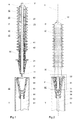
- Fig.1
- eine Aufsicht auf einen längs einer Achse geführten Schnitt durch eine Ausführungsform einer steckbaren Durchführung nach der Erfindung beim Einstecken in eine als Transformator ausgeführten Komponente einer Hochspannungsanlage,
- Fig.2
- eine Seitenansicht der Steckdurchführung nach
Fig.1 nach Einstecken in den Transformator, wobei eine beim Einstecken gebildete Steckverbindung längs der Achse geschnitten dargestellt ist, und - Fig.3
- in vergrösserter Darstellung einen umrandet dargestellten Abschnitt der Steckverbindung der Durchführung nach
Fig.2 . - In allen Figuren bezeichnen gleiche Bezugszeichen auch gleichwirkende Teile. Eine in den
Figuren 1 und 2 dargestellte, längs einer Achse A erstreckte Durchführung D enthält in koaxialer Anordnung folgende Teile: - einen längs der Achse A geführten Stromleiter 10, dessen unteres Ende einen als Stift ausgeführten Steckkontakt 11 aufweist und in dessen oberes Ende ein Anschluss 12 an einen externen Hochspannungsleiter eingeformt ist,
- einen als Rotationskörper ausgeführten Isolator 20, der einen auf der Aussenfläche des Stromleiters 10 befestigten, starren Kondensatorwickel 40 und eine auf einer Stirnfläche des Kondensatorwickels 40 befestigte, elastisch verformbare Isolierung 24 aufweist,
- einen auf der Aussenfläche des Isolators 20 befestigten Montageflansch 30, und
- eine von einem hydrophoben Polymer, wie typischerweise Silicon oder EPDM, gebildete Beschirmung 50, welche als Schutz vor der Witterung, vor Schmutz und/oder vor Strahlung im allgemeinen auf einen Abschnitt der Aussenfläche des Isolators 20 aufgebracht wird, der sich in axialer Richtung vom Montageflansch 30 auf den Stromanschluss 12 erstreckt.
- Der Isolator 20 weist einen sich verjüngenden unteren Abschnitt 21 sowie einen an diesen Abschnitt sich anschliessenden Abschnitt 22 auf, der vorwiegend zylinderförmig ausgebildet ist. Der Abschnitt 22 ist durch den Montageflansch 30 hindurch zum Freiluftanschluss 12 geführt, wohingegen der Abschnitt 21 erst unterhalb des Montageflansches 30 zwischen diesem und dem Steckkontakt 11 angeordnet ist. Der Kondensatorwickel 40 ist in den Isolator 20 integriert und weist voneinander elektrisch isolierte Kondensatorbeläge 41 auf, die in radialer Richtung durch Isolierfolie 42, welche typischerweise Papier und/oder Kunststoff enthält, mit Abstand zueinander gehalten sind. Die Längen der Kondensatorbeläge 41 sowohl in Richtung zum Freiluftanschluss 12 als auch in Richtung zum Steckkontakt 11 verkleinern sich mit zunehmendem, radialem Abstand zum Stromleiter 10 stetig. Die in die Folie 42 eingewickelten oder auf die Folie aufgedruckten, elektrisch leitenden Kondensatorbeläge 41 und insbesondere deren dem Steckkontakt 11 zugewandten Enden sind in eine gehärtete Polymermatrix 23 eingebettet.
- Die gehärtete Polymermasse 23 weist ein gefülltes oder ein ungefülltes Polymer, typischerweise auf der Basis eines Epoxidharzes, auf. Gegebenenfalls kann das Isoliermaterial 23 zusätzlich einen pulverförmigen Füllstoff, etwa auf der Basis von Quarz, enthalten. Die Fertigung des Kondensatorwickels 40 resp. der Durchführung wird erleichtert, wenn die Isolierfolie 42 und gegebenenfalls auch die Kondensatorbeläge 41 geeignet bemessene Öffnungen aufweisen. Beim Imprägnieren eines durch Wickeln der Isolierfolie 42 und durch Einbringen der Kondensatorbeläge 41 vorgefertigten Kondensatorwickels mit der ungehärteten Polymermasse können dann die Partikel des Füllstoffs leicht durch diese Öffnungen dringen.
- Der Kondensatorwickel 40 dient der Steuerung eines elektrischen Feldes, welches sich während des Betriebs der Durchführung D zwischen dem dann auf Hochspannungspotential befindlichen Stromleiter 10 und dem dann auf Erdpotential gehaltenen Montageflansch 30 ausbildet.
- Die sich verjüngende äussere Fläche des Isolatorabschnitts 21 wird von der auf einer Stirnseite des Kondensatorwickels 40 gehaltenen, elastisch verformbaren Isolierung 24 gebildet. Diese Isolierung enthält mit Vorteil ein Elastomer, etwa auf der Basis EPDM oder Silicon. Sie erstreckt sich von der Unterseite des Montageflansches 30 bis zum Steckkontakt 11. Sie wird erst dann auf den Kondensatorwickel 40 aufgebracht, wenn der Montageflansch 30 etwa durch Verklemmen oder durch Kleben am Kondensatorwickel 40 festgesetzt ist. In fertigungstechnisch vorteilhafter Weise wird dann die Isolierung 24 zusammen mit der Beschirmung 50 auf den Kondensatorwickel 40 aufgegossen.
- Aus
Fig.1 ist zu erkennen, dass die Durchführung D längs der Achse A nach unten geführt und in ein als Buchse ausgeführtes Steckteil 60 eines Transformators T eingesteckt werden kann. Der Transformator T weist ein auf Erdpotential befindliches und mit einem flüssigen oder gasförmigen Isoliermittel 61, wie insbesondere Isolieröl, gefülltes Metallgehäuse 62 auf. Ein mit einer nicht dargestellten Oberspannungswicklung verbundener und ebenfalls entlang der Achse A erstreckter Stromleiter 63 des Transformators T ist an seinem oberen Ende an einer Isolierhülse 64 des Steckteils 60 gehalten und weist einen als Hülse ausgeführten Steckkontakt 65 auf. Die den Stromleiter 63 haltende und den Steckkontakt 65 auf der Achse A zentrierende Isolierhülse 64 ist an einem als Flanschansatz ausgebildeten Teil des Gehäuses 62 isoliermitteldicht befestigt und verjüngt sich entlang der Achse A von der Befestigungsstelle stetig nach unten ins Innere des Transformators T. An dem im Inneren des Transformators gelegenen, unteren Ende der Isolierhülse 64 sind der Steckkontakt 65 und eine mit dem Stromleiter 63 elektrisch leitend verbundene Steuerelektrode 66 gehalten. Die nach innen weisende Fläche der Isolierhülse 64 weist weitgehend die gleiche Kontur wie die nach aussen weisende Fläche des sich verjüngenden Isolatorabschnitts 21 auf. - Wie aus
Fig.2 ersichtlich ist, bildet sich beim Einstecken der Durchführung D in das ersichtlich als Buchse ausgeführte Steckteil 60 zwischen der zur Achse A weisenden Innenfläche der Isolierhülse 64 und der von der Achse A weg nach aussen weisenden Fläche des verjüngenden Isolatorabschnitt 21 eine Fuge F aus. Beim Einstecken kommen die Steckkontakte 11 und 65 miteinander in Eingriff und wird so eine Stromverbindung zwischen den beiden Stromleitern 10 und 63 hergestellt. Danach wird der Montageflansch 30 mit Hilfe von nicht dargestellten Schrauben am Metallgehäuse 62 festgesetzt. Dabei wird die Isolierung 24 gegen die Innenfläche der Isolierhülse 64 gepresst und elastisch verformt, wodurch sich die Fuge F dielektrisch verfestigt. - Beim Fertigen des Kondensatorwickels 40 kann durch Einbringen längenmässig geeignet abgestufter Kondensatorbeläge 41 an geeigneten Positionen eine sehr genaue Steuerung des zwischen dem Stromleiter 10 und dem Montageflansch 30 wie auch dem Metallgehäuse 62 wirkenden elektrischen Feldes erreicht werden. Es wird so eine feinstufige Homogenisierung des elektrische Feldes sowohl in einem oberhalb des Montageflansches 30 gelegenen, dem Isoliermittel Luft ausgesetzten äusseren Bereich als auch in einem unterhalb des Montageflansches 30 gelegenen, dem Isoliermittel des Transformators T, also insbesondere einem Isolieröl, ausgesetzten internen Bereich und damit auch in der Fuge F erreicht. Es werden so in fertigungstechnisch einfacher Weise die in jedem der beiden Bereiche und in der Fuge anstehenden speziellen Feldsteueraufgaben gelöst. Der äussere Bereich weist - wie dargestellt - als Isoliermittel im allgemeinen zwar Luft auf, kann aber ein anderes Isoliermittel aufweisen, bei einem Kabelendverschluss beispielsweise Öl, bei einer gasisolierten Schaltanlage ein Isoliergas, wie typischerweise SF6.
- Anstelle eines mit Isolieröl gefüllten Transformators T kann die Hochspannungsanlage auch eine Komponente - etwa ein Schaltgerät - einer mit einem Isoliergas - wie insbesondere SF6 - gefüllten, metallgekapselten Schaltanlage enthalten.
- In einer die Durchführung D enthaltenden Hochspannungsanlage wird eine besonders feine Steuerung des elektrischen Feldes im Bereich der Isolierhülse 64 und insbesondere in der Fuge F erreicht, wenn das Steckteil 60 als Feldsteuerelement ausgebildet ist. Dies kann durch die bei Betrieb der Anlage auf Hochspannungspotential geführte Steuerelektrode 66 oder aber auch durch Verwendung von feldsteuerndem Material in der Isolierhülse 64 oder durch gemeinsamen Einsatz der Steuerelektrode 66 und des feldsteuernden Isoliermaterials in der Isolierhülse erreicht werden.
- Wie aus
Fig.3 ersichtlich ist, kann zusätzlich zur oder anstelle der elastisch verformbaren Isolierung 24 eine elastisch verformbare Isolierung 67 auch in die Isolierhülse 64 integriert werden. Bildet diese - vorzugsweise als Elastomer auf der Basis Silicon oder EPDM ausgeführte - Isolierung die die Fuge F begrenzende Fläche der Isolierhülse 64, so wird beim Einstecken der Durchführung D in den Transformator T die dielektrische Festigkeit der Fuge zusätzlich verbessert. - Aus
Fig.3 ist ferner zu erkennen, dass die dem Steckkontakt 11 zugewandten Enden der Kondensatorbeläge 41 auf einer an die Kontur der Fuge F angepassten Hüllfläche H liegen. Es wird so eine besonders gleichmässige Steuerung des elektrischen Feldes in der Fuge F erreicht. - Aus
Fig.3 ist auch ersichtlich, dass der Kondensatorwickel 40 zwei im sich verjüngenden Isolatorschnitt 21 gelegene Abschnitte 43, 44 aufweist. Der Abschnitt 43 ist zylinderförmig ausgebildet und ist durch einen ringförmig um die Achse A geführten, stufenförmig ausgebildeten Absatz 45 von dem einen geringeren Durchmesser aufweisenden, sich nach unten (in Richtung des Steckkontakts 11) verjüngenden Abschnitt 44 abgesetzt. Die Isolierung hintergreift der Absatz 45 und verbessert so die Haftung der Isolierung 24 auf dem Kondensatorwickel 40. Dies ist beim Einstecken der Durchführung D ins Steckteil 60 von Bedeutung, da ab diesem Zeitpunkt die Isolierung 24 entgegen der Steckrichtung mit grossen Scherkräften belastet wird. Der Absatz nimmt einen Teil der Scherkräfte auf und verbessert dementsprechend die Haftung der Isolierung 24 auf dem Kondensatorwickel 40. -
- 10
- Stromleiter
- 11
- Steckkontakt
- 12
- externer Anschluss
- 20
- Isolator
- 21, 22
- Abschnitte des Isolators 20
- 23
- gehärtetes Polymermaterial
- 24
- Isolierung
- 30
- Montageflansch
- 40
- Kondensatorwickel
- 41
- Kondensatorbeläge
- 42
- Isolierfolie
- 43
- zylinderförmiger Abschnitt des Kondensatorwickels
- 44
- sich verjüngender Abschnitt des Kondensatorwickels
- 45
- Absatz
- 50
- Beschirmung
- 60
- Steckteil
- 61
- Isoliermittel
- 62
- Metallgehäuse
- 63
- Stromleiter
- 64
- Isolierhülse
- 65
- Steckkontakt
- 66
- Steuerelektrode
- 67
- Isolierung
- A
- Achse
- D
- Durchführung
- F
- Fuge
- H
- Hüllfläche
- T
- Transformator
Claims (13)
- Steckbare Hochspannungsdurchführung (D) zum Anschliessen eines externen Stromleiters an eine mit einem flüssigen oder gasförmigen Isoliermittel (61) gefüllte, metallgekapselte Komponente (T) einer Hochspannungsanlage, enthaltend in koaxialer Anordnung einen längs einer Achse (A) geführten Stromleiter (10) mit einem Steckkontakt (11) und einem Anschluss (12) für den externen Leiter, einen am Stromleiter (10) befestigten Isolator (20), einen am Isolator (20) befestigten Montageflansch (30) und eine den Stromleiter (10) umfassende Vorrichtung zum Steuern des beim Anlegen von Hochspannung wirkenden elektrischen Felds, bei der der Isolator (20) einen sich verjüngenden Abschnitt (21) aufweist, der nach Einstecken der Durchführung (D) in ein die Komponente (T) der Hochspannungsanlage isoliermitteldicht abschliessendes Steckteil (60) eine Fuge (F) dielektrisch verfestigt, die zwischen einer Isolierhülse (64) des Steckteils (60) und dem sich verjüngenden Abschnitt (21) des Isolators angeordnet ist, dadurch gekennzeichnet, dass die Feldsteuervorrichtung als Kondensatorwickel (40) ausgeführt ist, dass der Kondensatorwickel (40) voneinander elektrisch isolierte Kondensatorbeläge (41) aufweist, die in radialer Richtung durch Isolierfolie (42) voneinander mit Abstand gehalten und durch Einbetten des Kondensatorwickels (40) in eine gehärtete Polymermasse (23) in den Isolator (20) integriert sind, und dass die Kondensatorbeläge (41) durch den Montageflansch (30) hindurch in den sich verjüngenden Abschnitt des Isolators (20) geführt sind.
- Durchführung nach Anspruch 1, dadurch gekennzeichnet, dass eine die Fuge (F) begrenzende Fläche des Isolatorabschnitts (21) von einer auf dem Kondensatorwickel (40) gehaltenen, elastisch verformbaren Isolierung (24) gebildet ist.
- Durchführung nach Anspruch 2, dadurch gekennzeichnet, dass die elastisch verformbare Isolierung (24) als Elastomer ausgeführt ist.
- Durchführung nach einem der Ansprüche 2 oder 3, dadurch gekennzeichnet, dass die elastisch verformbare Isolierung (24) einen in den Kondensatorwickel (40) eingeformten Absatz (45) hintergreift.
- Durchführung nach einem der Ansprüche 1 bis 4, dadurch gekennzeichnet, dass auf einer Aussenfläche des Isolators (20) eine Beschirmung (50) aufgebracht ist, die in axialer Richtung vom Montageflansch (30) auf einen Anschluss (12) des Stromleiters (10) geführt ist.
- Durchführung nach Anspruch 5, dadurch gekennzeichnet, dass die gehärtete Polymermasse (23) einen Füllstoff enthält, der als Diffusionsbarriere für von aussen eindringendes Wasser wirkt.
- Durchführung nach einem der Ansprüche 5 oder 6, dadurch gekennzeichnet, dass die Beschirmung (50) auf einer Beschichtung des Isolators (20) angeordnet ist, die als Diffusionsbarriere für eindringendes Wasser wirkt.
- Durchführung nach einem der Ansprüche 1 bis 7, dadurch gekennzeichnet, dass die dem Steckkontakt (11) zugewandten Enden der Kondensatorbeläge (41) auf einer an die Kontur der Fuge (F) angepassten Hüllfläche (H) liegen.
- Hochspannungsanlage mit einer mit einem flüssigen oder gasförmigen Isoliermittel (61) gefüllten Komponente (T) und mit einer steckbaren Durchführung (D) nach einem der Ansprüche 1 bis 8, welche in ein die Komponente (T) der Hochspannungsanlage isoliermitteldicht abschliessendes und eine Isolierhülse (64) enthaltendes Steckteil (60) eingesteckt ist, dadurch gekennzeichnet, dass das Steckteil (60) als Feldsteuerelement ausgebildet ist.
- Hochspannungsanlage nach Anspruch 9, dadurch gekennzeichnet, dass die Isolierhülse (64) eine auf Hochspannungspotential führbare Steuerelektrode (66) trägt.
- Hochspannungsanlage nach einem der Ansprüche 9 oder 10, dadurch gekennzeichnet, dass die Isolierhülse (64) feldsteuerndes Isoliermaterial enthält.
- Hochspannungsanlage nach einem der Ansprüche 9 bis 11, dadurch gekennzeichnet, dass eine die Fuge (F) begrenzende Fläche der Isolierhülse (64) von einer elastisch verformbaren Isolierung (67) gebildet ist.
- Hochspannungsanlage nach Anspruch 12, dadurch gekennzeichnet, dass die elastisch verformbare Isolierung (67) als Elastomer ausgeführt ist.
Priority Applications (6)
| Application Number | Priority Date | Filing Date | Title |
|---|---|---|---|
| EP10177794.4A EP2431982B1 (de) | 2010-09-21 | 2010-09-21 | Steckbare Durchführung und Hochspannungsanlage mit einer solchen Durchführung |
| RU2011138647/07A RU2475877C1 (ru) | 2010-09-21 | 2011-09-20 | Штекерный ввод и высоковольтная установка с штекерным вводом |
| KR1020110095186A KR101249785B1 (ko) | 2010-09-21 | 2011-09-21 | 플러그-인 부싱, 및 이와 같은 부싱을 갖는 고전압 설비 |
| CN201110291644.7A CN102568757B (zh) | 2010-09-21 | 2011-09-21 | 插塞式套管和具有这样的套管的高电压设施 |
| US13/238,831 US8455763B2 (en) | 2010-09-21 | 2011-09-21 | Plug-in bushing and high-voltage installation having a bushing such as this |
| BRPI1105755-6A BRPI1105755B1 (pt) | 2010-09-21 | 2011-09-21 | bucha de alta tensão de plugar e instalação de alta tensão dotada de um componente que é preenchido com um agente isolante líquido ou gasoso |
Applications Claiming Priority (1)
| Application Number | Priority Date | Filing Date | Title |
|---|---|---|---|
| EP10177794.4A EP2431982B1 (de) | 2010-09-21 | 2010-09-21 | Steckbare Durchführung und Hochspannungsanlage mit einer solchen Durchführung |
Publications (2)
| Publication Number | Publication Date |
|---|---|
| EP2431982A1 EP2431982A1 (de) | 2012-03-21 |
| EP2431982B1 true EP2431982B1 (de) | 2014-11-26 |
Family
ID=43629553
Family Applications (1)
| Application Number | Title | Priority Date | Filing Date |
|---|---|---|---|
| EP10177794.4A Active EP2431982B1 (de) | 2010-09-21 | 2010-09-21 | Steckbare Durchführung und Hochspannungsanlage mit einer solchen Durchführung |
Country Status (6)
| Country | Link |
|---|---|
| US (1) | US8455763B2 (de) |
| EP (1) | EP2431982B1 (de) |
| KR (1) | KR101249785B1 (de) |
| CN (1) | CN102568757B (de) |
| BR (1) | BRPI1105755B1 (de) |
| RU (1) | RU2475877C1 (de) |
Cited By (2)
| Publication number | Priority date | Publication date | Assignee | Title |
|---|---|---|---|---|
| DE102016220852A1 (de) * | 2016-10-24 | 2018-04-26 | Siemens Aktiengesellschaft | Mobiler Transformatordurchführungsanschluss |
| DE102017212977A1 (de) * | 2017-07-27 | 2019-01-31 | Siemens Aktiengesellschaft | Steckbare Hochspannungsdurchführung und elektrisches Gerät mit der steckbaren Hochspannungsdurchführung |
Families Citing this family (33)
| Publication number | Priority date | Publication date | Assignee | Title |
|---|---|---|---|---|
| DE102012204052B4 (de) * | 2012-03-15 | 2022-12-29 | Siemens Energy Global GmbH & Co. KG | Hochspannungsdurchführung mit leitenden Einlagen für Gleichspannung und Verfahren zu ihrer Herstellung |
| CN102957122A (zh) * | 2012-12-20 | 2013-03-06 | 沈阳华利能源设备制造有限公司 | 一种插入式连接的固体绝缘套管 |
| ES2635625T3 (es) * | 2013-07-30 | 2017-10-04 | Abb Schweiz Ag | Dispositivo de conexión para un aparato conmutador |
| US9601912B2 (en) * | 2014-06-23 | 2017-03-21 | Schneider Electric USA, Inc. | Compact transformer bushing |
| DE102014222690B4 (de) | 2014-11-06 | 2024-10-02 | Siemens Healthineers Ag | Detektormodul für einen Röntgendetektor |
| KR101720237B1 (ko) * | 2015-05-26 | 2017-04-10 | 주식회사 효성 | 콘덴서 부싱 및 그 제조방법 |
| DK3148027T3 (da) * | 2015-09-25 | 2020-03-23 | Abb Schweiz Ag | Kabelforskruning til forbindelse af et højspændingskabel til en højspændingskomponent |
| EP3148010A1 (de) * | 2015-09-25 | 2017-03-29 | ABB Schweiz AG | Kabelverschraubung zur verbindung eines hochspannungskabels an eine hochspannungskomponente oder ein anderes hochspannungskabel |
| EP3196901B1 (de) * | 2016-01-25 | 2018-04-04 | General Electric Technology GmbH | Hochspannungsanlage |
| US11146053B2 (en) * | 2016-01-29 | 2021-10-12 | Power Hv Inc. | Bushing for a transformer |
| DE102016203776A1 (de) * | 2016-03-08 | 2017-09-14 | Siemens Aktiengesellschaft | Wicklungsanordnung mit Steckdurchführung |
| DE102016207405A1 (de) * | 2016-04-29 | 2017-11-02 | Siemens Aktiengesellschaft | Transformator mit einsteckbaren Hochspannungsdurchführungen |
| US10027051B1 (en) * | 2017-02-20 | 2018-07-17 | Robert Bosch Gmbh | Hybrid electrical connector |
| EP3639282B1 (de) * | 2017-07-12 | 2024-07-03 | HSP Hochspannungsgeräte GmbH | Steckbare hochspannungsdurchführung und elektrisches gerät mit steckbarer hochspannungsdurchführung |
| EP3435493B1 (de) | 2017-07-27 | 2020-03-25 | Siemens Aktiengesellschaft | Steckbare hochspannungsdurchführung und hochspannungsanlage mit der steckbaren hochspannungsdurchführung |
| DE102018201224A1 (de) | 2018-01-26 | 2019-08-01 | Siemens Aktiengesellschaft | Steckbare Hochspannungsdurchführung und elektrisches Gerät mit der steckbaren Hochspannungsdurchführung |
| US10818434B2 (en) | 2018-04-11 | 2020-10-27 | Eaton Intelligent Power Limited | Adaptor for a capacitor |
| DE102018215274A1 (de) * | 2018-09-07 | 2020-03-12 | Siemens Aktiengesellschaft | Anordnung und Verfahren zur Potentialabsteuerung in der Hochspannungstechnik |
| CN109557354B (zh) * | 2018-10-17 | 2023-11-07 | 全球能源互联网研究院有限公司 | 一种含有阻容混联拓扑单元的宽频电压互感器 |
| CN109346293A (zh) * | 2018-10-23 | 2019-02-15 | 南京智达电气设备有限公司 | 一种组合型特高压胶浸纸套管 |
| EP3667684B1 (de) * | 2018-12-12 | 2024-08-21 | Hitachi Energy Ltd | Elektrische durchführung |
| KR102182989B1 (ko) | 2019-03-29 | 2020-11-26 | 대한전선 주식회사 | 고전압 설비용 건식 플러그-인 부싱 |
| KR102182988B1 (ko) | 2019-03-29 | 2020-11-26 | 대한전선 주식회사 | 건식 플러그-인 부싱, 그 제조방법 및 이와 같은 부싱을 포함하는 고전압 설비 |
| CN114709788A (zh) * | 2019-06-26 | 2022-07-05 | 安徽伊法拉电气股份有限公司 | 一种冷缩电缆户外终端 |
| EP3826035A1 (de) * | 2019-11-20 | 2021-05-26 | ABB Power Grids Switzerland AG | Zugstangenbuchse mit abgedichtetem unterem kontakt |
| CN220232869U (zh) * | 2019-12-04 | 2023-12-22 | 西门子能源全球有限公司 | 具有可插接的高压套管和用于容纳高压套管的设备连接件的电气设备 |
| EP3913749B1 (de) * | 2020-05-19 | 2024-04-10 | Hitachi Energy Ltd | Buchse mit feldsteuerelement |
| KR102837759B1 (ko) * | 2020-09-01 | 2025-07-23 | 엘에스전선 주식회사 | 중전기 장비용 부싱장치 |
| KR102802748B1 (ko) * | 2020-09-01 | 2025-04-30 | 엘에스전선 주식회사 | 중전기 장비용 부싱장치 |
| CN114640070B (zh) * | 2020-12-15 | 2025-03-11 | 北京瑞恒新源投资有限公司 | 封闭式组合套管 |
| EP4024635A1 (de) | 2020-12-29 | 2022-07-06 | Schneider Electric USA, Inc. | Schaltvorrichtung mit reduzierter teilentladung und verbesserten dreipunkteigenschaften |
| US12100939B2 (en) * | 2022-04-21 | 2024-09-24 | Jst Power Equipment, Inc. | Circuit breaker with terminal bushings having dynamic seal |
| EP4383490A1 (de) * | 2022-12-09 | 2024-06-12 | NKT HV Cables AB | Prüfhilfsvorrichtung für ein kabel und verfahren zur bereitstellung einer prüfhilfsvorrichtung |
Family Cites Families (25)
| Publication number | Priority date | Publication date | Assignee | Title |
|---|---|---|---|---|
| GB689560A (en) * | 1952-01-28 | 1953-04-01 | British Thomson Houston Co Ltd | Improvements in and relating to terminal bushings for electric transformers and the like |
| DE1189600B (de) * | 1961-04-27 | 1965-03-25 | Westinghouse Electric Corp | Elektrische Hochspannungsdurchfuehrung mit zentralem Durchfuehrungsleiter |
| DE2946172A1 (de) * | 1979-11-15 | 1981-05-21 | Siemens AG, 1000 Berlin und 8000 München | Hochspannungsdurchfuehrung |
| DE3001810A1 (de) * | 1980-01-18 | 1981-07-23 | Siemens AG, 1000 Berlin und 8000 München | Folienisolierte hochspannungsdurchfuehrung mit potentialsteuereinlagen |
| DD161044A3 (de) * | 1980-11-04 | 1984-08-29 | Liebknecht Transformat | Sicherungseinrichtung fuer hochspannungs-kondensator-durchfuehrung |
| US4500745A (en) * | 1983-03-03 | 1985-02-19 | Interpace Corporation | Hybrid electrical insulator bushing |
| JPS612312A (ja) * | 1984-06-15 | 1986-01-08 | Hitachi Ltd | コンデンサ形ブツシングpd |
| FR2581791B1 (fr) * | 1985-05-13 | 1988-11-04 | Merlin Gerin | Mecanisme de fermeture manuelle brusque d'un appareil de coupure de courant |
| CN2129450Y (zh) * | 1992-07-16 | 1993-04-07 | 沈阳变压器厂 | 一种固体套管 |
| WO1999045550A1 (de) * | 1998-03-05 | 1999-09-10 | HSP Hochspannungsgeräte Porz GmbH | Durchführung für eine hohe elektrische spannung |
| DE19856123C2 (de) * | 1998-12-04 | 2000-12-07 | Siemens Ag | Hohlisolator |
| SE526713C2 (sv) * | 2003-07-11 | 2005-10-25 | Abb Research Ltd | Genomföring samt förfarande för tillverkning av genomföringen |
| ATE546818T1 (de) * | 2004-03-15 | 2012-03-15 | Abb Research Ltd | Hochspannungsdurchführung mit feldsteuermaterial |
| EP1622173A1 (de) * | 2004-07-28 | 2006-02-01 | Abb Research Ltd. | Hochspannungsdurchführung |
| DE102004046134A1 (de) * | 2004-08-06 | 2006-03-16 | Südkabel GmbH | Freiluftendverschluss |
| CN101253582B (zh) * | 2005-06-07 | 2011-06-29 | Abb研究有限公司 | 套管、使用该套管的高压/中压设备及制造该套管的方法 |
| EP1798740B1 (de) * | 2005-12-14 | 2011-08-31 | ABB Research Ltd. | Hochspannungsdurchführung |
| US8049108B2 (en) * | 2005-12-30 | 2011-11-01 | Abb Technology Ltd. | High voltage bushing and high voltage device comprising such bushing |
| DK1811626T3 (en) * | 2006-01-24 | 2016-08-01 | Nexans | Electrical bushing |
| CN101136280A (zh) * | 2006-08-31 | 2008-03-05 | Abb技术有限公司 | 高压设备、高压套管以及装配所述设备的方法 |
| EP1939897A1 (de) * | 2006-12-28 | 2008-07-02 | ABB Research Ltd. | Isolierstruktur mit einem elektrischen Feld bildende Schirme |
| RU64823U1 (ru) * | 2007-04-12 | 2007-07-10 | Закрытое акционерное общество "Группа "А.Д.Д." | Мобильная трансформаторная подстанция |
| DE102007022641A1 (de) | 2007-05-15 | 2008-11-20 | Areva Energietechnik Gmbh | Elektrischer Transformator |
| EP2053616A1 (de) * | 2007-10-26 | 2009-04-29 | ABB Research Ltd. | Hochspannungs-Freiluftdurchführung |
| EP2117015A1 (de) * | 2008-05-06 | 2009-11-11 | ABB Technology AG | Hochspannungsbuchse und Hochspannungsvorrichtung mit einer derartigen Buchse |
-
2010
- 2010-09-21 EP EP10177794.4A patent/EP2431982B1/de active Active
-
2011
- 2011-09-20 RU RU2011138647/07A patent/RU2475877C1/ru active
- 2011-09-21 CN CN201110291644.7A patent/CN102568757B/zh active Active
- 2011-09-21 KR KR1020110095186A patent/KR101249785B1/ko active Active
- 2011-09-21 US US13/238,831 patent/US8455763B2/en active Active
- 2011-09-21 BR BRPI1105755-6A patent/BRPI1105755B1/pt active IP Right Grant
Cited By (3)
| Publication number | Priority date | Publication date | Assignee | Title |
|---|---|---|---|---|
| DE102016220852A1 (de) * | 2016-10-24 | 2018-04-26 | Siemens Aktiengesellschaft | Mobiler Transformatordurchführungsanschluss |
| DE102017212977A1 (de) * | 2017-07-27 | 2019-01-31 | Siemens Aktiengesellschaft | Steckbare Hochspannungsdurchführung und elektrisches Gerät mit der steckbaren Hochspannungsdurchführung |
| US11469014B2 (en) | 2017-07-27 | 2022-10-11 | Siemens Energy Global GmbH & Co. KG | Electrical device having an insertable high-voltage bushing |
Also Published As
| Publication number | Publication date |
|---|---|
| CN102568757A (zh) | 2012-07-11 |
| KR20120030984A (ko) | 2012-03-29 |
| KR101249785B1 (ko) | 2013-04-03 |
| RU2475877C1 (ru) | 2013-02-20 |
| BRPI1105755B1 (pt) | 2021-01-19 |
| BRPI1105755A2 (pt) | 2013-05-28 |
| US20120071014A1 (en) | 2012-03-22 |
| CN102568757B (zh) | 2014-11-26 |
| EP2431982A1 (de) | 2012-03-21 |
| US8455763B2 (en) | 2013-06-04 |
Similar Documents
| Publication | Publication Date | Title |
|---|---|---|
| EP2431982B1 (de) | Steckbare Durchführung und Hochspannungsanlage mit einer solchen Durchführung | |
| EP3229242B1 (de) | Hochspannungsdurchführung | |
| DE2348895C2 (de) | Verbindung für Starkstromkabel | |
| EP2182602B1 (de) | Vorrichtung für eine Verbindungungsstelle zwischen zwei elektrischen Hochspannungskabeln | |
| DE69738421T2 (de) | Kabelendstück | |
| DE19926950A1 (de) | Kabelendgarnitur | |
| EP3639282A1 (de) | Steckbare hochspannungsdurchführung und elektrisches gerät mit steckbarer hochspannungsdurchführung | |
| DE102006036233B4 (de) | Freiluftendverschluss | |
| EP3427276B1 (de) | Transformator mit einsteckbaren hochspannungsdurchführungen | |
| EP2715743B1 (de) | Elektrische komponente für eine hochspannungsanlage | |
| DE69401800T2 (de) | Mehrzweckstromdurchführung | |
| EP3893342B1 (de) | Kabelanschluss | |
| DE4015929A1 (de) | Isolator | |
| EP2600358B1 (de) | Überspannungsableiter | |
| EP3724901B1 (de) | Hochspannungsdurchführung, elektrisches gerät mit hochspannungsdurchführung und verfahren zur herstellung des elektrischen gerätes | |
| EP3721516B1 (de) | Leiterseilüberbrückungsvorrichtung und verwendung in einem umrüst- oder herstellungsverfahren für freileitungsmasten | |
| EP0773601A2 (de) | Sicherheitssteckverbindung | |
| DE19856025C2 (de) | Kompakte Übergangsmuffe | |
| DE19539060A1 (de) | Hochspannungs-Hochleistungs-Sicherung für eine elektrische Verbindungsleitung | |
| EP3631821A1 (de) | Steckbare hochspannungsdurchführung und elektrisches gerät mit der steckbaren hochspannungsdurchführung | |
| EP2403087B1 (de) | Anordnung zum Verbinden von zwei papierisolierten Hochspannungskabeln | |
| EP2515313A1 (de) | Hochspannungsdurchführung | |
| DE1916079C3 (de) | Sammelschienenabzweig für MittelspannungsschaltzeUe | |
| EP4007924A1 (de) | Messanordnung zum messen eines spannungspotentials an einem leiter in einer leistungsschaltvorrichtung und entsprechende leistungsschaltvorrichtung | |
| EP3266085B1 (de) | Feldsteuerelement für endverschlüsse von kabeln zu energieübertragung |
Legal Events
| Date | Code | Title | Description |
|---|---|---|---|
| PUAI | Public reference made under article 153(3) epc to a published international application that has entered the european phase |
Free format text: ORIGINAL CODE: 0009012 |
|
| AK | Designated contracting states |
Kind code of ref document: A1 Designated state(s): AL AT BE BG CH CY CZ DE DK EE ES FI FR GB GR HR HU IE IS IT LI LT LU LV MC MK MT NL NO PL PT RO SE SI SK SM TR |
|
| AX | Request for extension of the european patent |
Extension state: BA ME RS |
|
| 17P | Request for examination filed |
Effective date: 20120903 |
|
| GRAP | Despatch of communication of intention to grant a patent |
Free format text: ORIGINAL CODE: EPIDOSNIGR1 |
|
| RIC1 | Information provided on ipc code assigned before grant |
Ipc: H01R 13/53 20060101ALI20140701BHEP Ipc: H01F 27/04 20060101ALI20140701BHEP Ipc: H02G 15/072 20060101ALI20140701BHEP Ipc: H01B 17/28 20060101AFI20140701BHEP |
|
| INTG | Intention to grant announced |
Effective date: 20140722 |
|
| GRAS | Grant fee paid |
Free format text: ORIGINAL CODE: EPIDOSNIGR3 |
|
| GRAA | (expected) grant |
Free format text: ORIGINAL CODE: 0009210 |
|
| AK | Designated contracting states |
Kind code of ref document: B1 Designated state(s): AL AT BE BG CH CY CZ DE DK EE ES FI FR GB GR HR HU IE IS IT LI LT LU LV MC MK MT NL NO PL PT RO SE SI SK SM TR |
|
| REG | Reference to a national code |
Ref country code: GB Ref legal event code: FG4D Free format text: NOT ENGLISH |
|
| REG | Reference to a national code |
Ref country code: CH Ref legal event code: EP |
|
| REG | Reference to a national code |
Ref country code: AT Ref legal event code: REF Ref document number: 698597 Country of ref document: AT Kind code of ref document: T Effective date: 20141215 |
|
| REG | Reference to a national code |
Ref country code: IE Ref legal event code: FG4D Free format text: LANGUAGE OF EP DOCUMENT: GERMAN |
|
| REG | Reference to a national code |
Ref country code: DE Ref legal event code: R096 Ref document number: 502010008334 Country of ref document: DE Effective date: 20150108 |
|
| REG | Reference to a national code |
Ref country code: NL Ref legal event code: VDEP Effective date: 20141126 |
|
| REG | Reference to a national code |
Ref country code: LT Ref legal event code: MG4D |
|
| PG25 | Lapsed in a contracting state [announced via postgrant information from national office to epo] |
Ref country code: PT Free format text: LAPSE BECAUSE OF FAILURE TO SUBMIT A TRANSLATION OF THE DESCRIPTION OR TO PAY THE FEE WITHIN THE PRESCRIBED TIME-LIMIT Effective date: 20150326 Ref country code: FI Free format text: LAPSE BECAUSE OF FAILURE TO SUBMIT A TRANSLATION OF THE DESCRIPTION OR TO PAY THE FEE WITHIN THE PRESCRIBED TIME-LIMIT Effective date: 20141126 Ref country code: IS Free format text: LAPSE BECAUSE OF FAILURE TO SUBMIT A TRANSLATION OF THE DESCRIPTION OR TO PAY THE FEE WITHIN THE PRESCRIBED TIME-LIMIT Effective date: 20150326 Ref country code: LT Free format text: LAPSE BECAUSE OF FAILURE TO SUBMIT A TRANSLATION OF THE DESCRIPTION OR TO PAY THE FEE WITHIN THE PRESCRIBED TIME-LIMIT Effective date: 20141126 Ref country code: NL Free format text: LAPSE BECAUSE OF FAILURE TO SUBMIT A TRANSLATION OF THE DESCRIPTION OR TO PAY THE FEE WITHIN THE PRESCRIBED TIME-LIMIT Effective date: 20141126 Ref country code: NO Free format text: LAPSE BECAUSE OF FAILURE TO SUBMIT A TRANSLATION OF THE DESCRIPTION OR TO PAY THE FEE WITHIN THE PRESCRIBED TIME-LIMIT Effective date: 20150226 Ref country code: ES Free format text: LAPSE BECAUSE OF FAILURE TO SUBMIT A TRANSLATION OF THE DESCRIPTION OR TO PAY THE FEE WITHIN THE PRESCRIBED TIME-LIMIT Effective date: 20141126 |
|
| PG25 | Lapsed in a contracting state [announced via postgrant information from national office to epo] |
Ref country code: CY Free format text: LAPSE BECAUSE OF FAILURE TO SUBMIT A TRANSLATION OF THE DESCRIPTION OR TO PAY THE FEE WITHIN THE PRESCRIBED TIME-LIMIT Effective date: 20141126 Ref country code: LV Free format text: LAPSE BECAUSE OF FAILURE TO SUBMIT A TRANSLATION OF THE DESCRIPTION OR TO PAY THE FEE WITHIN THE PRESCRIBED TIME-LIMIT Effective date: 20141126 Ref country code: GR Free format text: LAPSE BECAUSE OF FAILURE TO SUBMIT A TRANSLATION OF THE DESCRIPTION OR TO PAY THE FEE WITHIN THE PRESCRIBED TIME-LIMIT Effective date: 20150227 Ref country code: HR Free format text: LAPSE BECAUSE OF FAILURE TO SUBMIT A TRANSLATION OF THE DESCRIPTION OR TO PAY THE FEE WITHIN THE PRESCRIBED TIME-LIMIT Effective date: 20141126 Ref country code: SE Free format text: LAPSE BECAUSE OF FAILURE TO SUBMIT A TRANSLATION OF THE DESCRIPTION OR TO PAY THE FEE WITHIN THE PRESCRIBED TIME-LIMIT Effective date: 20141126 |
|
| PG25 | Lapsed in a contracting state [announced via postgrant information from national office to epo] |
Ref country code: RO Free format text: LAPSE BECAUSE OF FAILURE TO SUBMIT A TRANSLATION OF THE DESCRIPTION OR TO PAY THE FEE WITHIN THE PRESCRIBED TIME-LIMIT Effective date: 20141126 Ref country code: SK Free format text: LAPSE BECAUSE OF FAILURE TO SUBMIT A TRANSLATION OF THE DESCRIPTION OR TO PAY THE FEE WITHIN THE PRESCRIBED TIME-LIMIT Effective date: 20141126 Ref country code: EE Free format text: LAPSE BECAUSE OF FAILURE TO SUBMIT A TRANSLATION OF THE DESCRIPTION OR TO PAY THE FEE WITHIN THE PRESCRIBED TIME-LIMIT Effective date: 20141126 Ref country code: DK Free format text: LAPSE BECAUSE OF FAILURE TO SUBMIT A TRANSLATION OF THE DESCRIPTION OR TO PAY THE FEE WITHIN THE PRESCRIBED TIME-LIMIT Effective date: 20141126 Ref country code: CZ Free format text: LAPSE BECAUSE OF FAILURE TO SUBMIT A TRANSLATION OF THE DESCRIPTION OR TO PAY THE FEE WITHIN THE PRESCRIBED TIME-LIMIT Effective date: 20141126 |
|
| REG | Reference to a national code |
Ref country code: DE Ref legal event code: R097 Ref document number: 502010008334 Country of ref document: DE |
|
| PG25 | Lapsed in a contracting state [announced via postgrant information from national office to epo] |
Ref country code: PL Free format text: LAPSE BECAUSE OF FAILURE TO SUBMIT A TRANSLATION OF THE DESCRIPTION OR TO PAY THE FEE WITHIN THE PRESCRIBED TIME-LIMIT Effective date: 20141126 |
|
| REG | Reference to a national code |
Ref country code: FR Ref legal event code: PLFP Year of fee payment: 6 |
|
| PLBE | No opposition filed within time limit |
Free format text: ORIGINAL CODE: 0009261 |
|
| STAA | Information on the status of an ep patent application or granted ep patent |
Free format text: STATUS: NO OPPOSITION FILED WITHIN TIME LIMIT |
|
| 26N | No opposition filed |
Effective date: 20150827 |
|
| PGFP | Annual fee paid to national office [announced via postgrant information from national office to epo] |
Ref country code: FR Payment date: 20150922 Year of fee payment: 6 |
|
| PG25 | Lapsed in a contracting state [announced via postgrant information from national office to epo] |
Ref country code: SI Free format text: LAPSE BECAUSE OF FAILURE TO SUBMIT A TRANSLATION OF THE DESCRIPTION OR TO PAY THE FEE WITHIN THE PRESCRIBED TIME-LIMIT Effective date: 20141126 |
|
| PG25 | Lapsed in a contracting state [announced via postgrant information from national office to epo] |
Ref country code: MC Free format text: LAPSE BECAUSE OF FAILURE TO SUBMIT A TRANSLATION OF THE DESCRIPTION OR TO PAY THE FEE WITHIN THE PRESCRIBED TIME-LIMIT Effective date: 20141126 Ref country code: LU Free format text: LAPSE BECAUSE OF FAILURE TO SUBMIT A TRANSLATION OF THE DESCRIPTION OR TO PAY THE FEE WITHIN THE PRESCRIBED TIME-LIMIT Effective date: 20150921 |
|
| REG | Reference to a national code |
Ref country code: CH Ref legal event code: PL |
|
| GBPC | Gb: european patent ceased through non-payment of renewal fee |
Effective date: 20150921 |
|
| REG | Reference to a national code |
Ref country code: IE Ref legal event code: MM4A |
|
| PG25 | Lapsed in a contracting state [announced via postgrant information from national office to epo] |
Ref country code: CH Free format text: LAPSE BECAUSE OF NON-PAYMENT OF DUE FEES Effective date: 20150930 Ref country code: GB Free format text: LAPSE BECAUSE OF NON-PAYMENT OF DUE FEES Effective date: 20150921 Ref country code: LI Free format text: LAPSE BECAUSE OF NON-PAYMENT OF DUE FEES Effective date: 20150930 Ref country code: IE Free format text: LAPSE BECAUSE OF NON-PAYMENT OF DUE FEES Effective date: 20150921 |
|
| REG | Reference to a national code |
Ref country code: AT Ref legal event code: MM01 Ref document number: 698597 Country of ref document: AT Kind code of ref document: T Effective date: 20150921 |
|
| PG25 | Lapsed in a contracting state [announced via postgrant information from national office to epo] |
Ref country code: AT Free format text: LAPSE BECAUSE OF NON-PAYMENT OF DUE FEES Effective date: 20150921 |
|
| REG | Reference to a national code |
Ref country code: DE Ref legal event code: R081 Ref document number: 502010008334 Country of ref document: DE Owner name: HITACHI ENERGY SWITZERLAND AG, CH Free format text: FORMER OWNER: ABB TECHNOLOGY AG, ZUERICH, CH Ref country code: DE Ref legal event code: R081 Ref document number: 502010008334 Country of ref document: DE Owner name: ABB SCHWEIZ AG, CH Free format text: FORMER OWNER: ABB TECHNOLOGY AG, ZUERICH, CH Ref country code: DE Ref legal event code: R081 Ref document number: 502010008334 Country of ref document: DE Owner name: ABB POWER GRIDS SWITZERLAND AG, CH Free format text: FORMER OWNER: ABB TECHNOLOGY AG, ZUERICH, CH Ref country code: DE Ref legal event code: R082 Ref document number: 502010008334 Country of ref document: DE Representative=s name: DENNEMEYER & ASSOCIATES S.A., DE Ref country code: DE Ref legal event code: R082 Ref document number: 502010008334 Country of ref document: DE Representative=s name: ZIMMERMANN & PARTNER PATENTANWAELTE MBB, DE |
|
| PG25 | Lapsed in a contracting state [announced via postgrant information from national office to epo] |
Ref country code: MT Free format text: LAPSE BECAUSE OF FAILURE TO SUBMIT A TRANSLATION OF THE DESCRIPTION OR TO PAY THE FEE WITHIN THE PRESCRIBED TIME-LIMIT Effective date: 20141126 |
|
| PG25 | Lapsed in a contracting state [announced via postgrant information from national office to epo] |
Ref country code: SM Free format text: LAPSE BECAUSE OF FAILURE TO SUBMIT A TRANSLATION OF THE DESCRIPTION OR TO PAY THE FEE WITHIN THE PRESCRIBED TIME-LIMIT Effective date: 20141126 Ref country code: HU Free format text: LAPSE BECAUSE OF FAILURE TO SUBMIT A TRANSLATION OF THE DESCRIPTION OR TO PAY THE FEE WITHIN THE PRESCRIBED TIME-LIMIT; INVALID AB INITIO Effective date: 20100921 Ref country code: BG Free format text: LAPSE BECAUSE OF FAILURE TO SUBMIT A TRANSLATION OF THE DESCRIPTION OR TO PAY THE FEE WITHIN THE PRESCRIBED TIME-LIMIT Effective date: 20141126 |
|
| REG | Reference to a national code |
Ref country code: FR Ref legal event code: ST Effective date: 20170531 |
|
| PG25 | Lapsed in a contracting state [announced via postgrant information from national office to epo] |
Ref country code: FR Free format text: LAPSE BECAUSE OF NON-PAYMENT OF DUE FEES Effective date: 20160930 Ref country code: BE Free format text: LAPSE BECAUSE OF NON-PAYMENT OF DUE FEES Effective date: 20150930 |
|
| PG25 | Lapsed in a contracting state [announced via postgrant information from national office to epo] |
Ref country code: TR Free format text: LAPSE BECAUSE OF FAILURE TO SUBMIT A TRANSLATION OF THE DESCRIPTION OR TO PAY THE FEE WITHIN THE PRESCRIBED TIME-LIMIT Effective date: 20141126 |
|
| PG25 | Lapsed in a contracting state [announced via postgrant information from national office to epo] |
Ref country code: MK Free format text: LAPSE BECAUSE OF FAILURE TO SUBMIT A TRANSLATION OF THE DESCRIPTION OR TO PAY THE FEE WITHIN THE PRESCRIBED TIME-LIMIT Effective date: 20141126 |
|
| PG25 | Lapsed in a contracting state [announced via postgrant information from national office to epo] |
Ref country code: AL Free format text: LAPSE BECAUSE OF FAILURE TO SUBMIT A TRANSLATION OF THE DESCRIPTION OR TO PAY THE FEE WITHIN THE PRESCRIBED TIME-LIMIT Effective date: 20141126 |
|
| REG | Reference to a national code |
Ref country code: DE Ref legal event code: R081 Ref document number: 502010008334 Country of ref document: DE Owner name: HITACHI ENERGY SWITZERLAND AG, CH Free format text: FORMER OWNER: ABB SCHWEIZ AG, BADEN, CH Ref country code: DE Ref legal event code: R082 Ref document number: 502010008334 Country of ref document: DE Representative=s name: DENNEMEYER & ASSOCIATES RECHTSANWALTSGESELLSCH, DE Ref country code: DE Ref legal event code: R081 Ref document number: 502010008334 Country of ref document: DE Owner name: HITACHI ENERGY LTD, CH Free format text: FORMER OWNER: ABB SCHWEIZ AG, BADEN, CH Ref country code: DE Ref legal event code: R082 Ref document number: 502010008334 Country of ref document: DE Representative=s name: DENNEMEYER & ASSOCIATES S.A., DE Ref country code: DE Ref legal event code: R081 Ref document number: 502010008334 Country of ref document: DE Owner name: ABB POWER GRIDS SWITZERLAND AG, CH Free format text: FORMER OWNER: ABB SCHWEIZ AG, BADEN, CH |
|
| REG | Reference to a national code |
Ref country code: DE Ref legal event code: R081 Ref document number: 502010008334 Country of ref document: DE Owner name: HITACHI ENERGY SWITZERLAND AG, CH Free format text: FORMER OWNER: ABB POWER GRIDS SWITZERLAND AG, BADEN, CH Ref country code: DE Ref legal event code: R081 Ref document number: 502010008334 Country of ref document: DE Owner name: HITACHI ENERGY LTD, CH Free format text: FORMER OWNER: ABB POWER GRIDS SWITZERLAND AG, BADEN, CH |
|
| P01 | Opt-out of the competence of the unified patent court (upc) registered |
Effective date: 20230527 |
|
| REG | Reference to a national code |
Ref country code: DE Ref legal event code: R082 Ref document number: 502010008334 Country of ref document: DE Representative=s name: DENNEMEYER & ASSOCIATES RECHTSANWALTSGESELLSCH, DE Ref country code: DE Ref legal event code: R082 Ref document number: 502010008334 Country of ref document: DE Representative=s name: DENNEMEYER & ASSOCIATES S.A., DE Ref country code: DE Ref legal event code: R081 Ref document number: 502010008334 Country of ref document: DE Owner name: HITACHI ENERGY LTD, CH Free format text: FORMER OWNER: HITACHI ENERGY SWITZERLAND AG, BADEN, CH |
|
| REG | Reference to a national code |
Ref country code: DE Ref legal event code: R082 Ref document number: 502010008334 Country of ref document: DE Representative=s name: DENNEMEYER & ASSOCIATES RECHTSANWALTSGESELLSCH, DE |
|
| PGFP | Annual fee paid to national office [announced via postgrant information from national office to epo] |
Ref country code: DE Payment date: 20250919 Year of fee payment: 16 |
|
| PGFP | Annual fee paid to national office [announced via postgrant information from national office to epo] |
Ref country code: IT Payment date: 20250923 Year of fee payment: 16 |