EP1577904B1 - Hochspannungsdurchführung mit Feldsteuermaterial - Google Patents
Hochspannungsdurchführung mit Feldsteuermaterial Download PDFInfo
- Publication number
- EP1577904B1 EP1577904B1 EP04405151A EP04405151A EP1577904B1 EP 1577904 B1 EP1577904 B1 EP 1577904B1 EP 04405151 A EP04405151 A EP 04405151A EP 04405151 A EP04405151 A EP 04405151A EP 1577904 B1 EP1577904 B1 EP 1577904B1
- Authority
- EP
- European Patent Office
- Prior art keywords
- field control
- bushing
- control element
- field
- mounting flange
- Prior art date
- Legal status (The legal status is an assumption and is not a legal conclusion. Google has not performed a legal analysis and makes no representation as to the accuracy of the status listed.)
- Expired - Lifetime
Links
Images

Classifications
-
- H—ELECTRICITY
- H01—ELECTRIC ELEMENTS
- H01B—CABLES; CONDUCTORS; INSULATORS; SELECTION OF MATERIALS FOR THEIR CONDUCTIVE, INSULATING OR DIELECTRIC PROPERTIES
- H01B17/00—Insulators or insulating bodies characterised by their form
- H01B17/26—Lead-in insulators; Lead-through insulators
- H01B17/28—Capacitor type
-
- H—ELECTRICITY
- H01—ELECTRIC ELEMENTS
- H01B—CABLES; CONDUCTORS; INSULATORS; SELECTION OF MATERIALS FOR THEIR CONDUCTIVE, INSULATING OR DIELECTRIC PROPERTIES
- H01B17/00—Insulators or insulating bodies characterised by their form
- H01B17/42—Means for obtaining improved distribution of voltage; Protection against arc discharges
Definitions
- the invention relates to the field of high or medium voltage technology, in particular electrical insulation and connection technology for grounded high voltage apparatus. It is based on a dielectric bushing and a high-voltage electrical apparatus according to the preamble of the independent claims.
- a high voltage insulator z As porcelain or composite material with a coating of field control material (FGM) disclosed.
- the field-controlling coating consists of varistor powder, z. Of doped zinc oxide (ZnO) embedded in a polymer matrix.
- the FGM coating serves to compare the field distribution on the insulator surface and is distributed so that part of the material is in electrical contact with both the ground electrode and the high voltage electrode. In this case, the FGM coating can only partially cover the insulator length and be concentrated in the field-loaded electrode regions.
- the FGM coating can be applied to the insulator surface, can be incorporated there in a shield or can be shielded by a weatherproof, electrically insulating protective layer to the outside.
- An equalization of the capacitive field load can be realized by alternating horizontal strips or bands of FGM coating and insulator material.
- the FGM coating may be applied in the form of a glaze or a paint, or mixed into a slurry or clay, applied to the porcelain insulator and fired there to a glaze or ceramic layer.
- the matrix for the FGM coating may be a polymer, an adhesive, a casting or a mastic or a gel.
- EP 1 042 756 discloses a glass fiber reinforced insulator tube which is impregnated on the inner surface and optionally also the outer surface with a resin which has a particulate filler with varistor properties, in particular zinc oxide.
- the GRP tube can be made by winding a fiberglass mesh which is impregnated with the varistor-filled resin at least on the outer layers.
- the insulator comprises an insulator body made of porcelain or composite material and a porcelain or silicone shield.
- the shield has a variable insulator screen density.
- Isolatorend Scheme For field relief in a Isolatorend Scheme turn the known shield electrode between the insulator body and conductor is present. It is now proposed to install an increased number of insulator screens in the heavily field-loaded area where the shielding electrode ends. Due to the increased insulator screen density, improved field relief is achieved in the end region of the shield electrode.
- the invention relates to a prior art, as shown in the US Pat. 3,318,995 is known.
- cast resin bushings are disclosed, which remain electrically reliable even with differential thermal expansion or shrinkage due to cavitation between metal and cast resin.
- regions with increased cracking tendency are electrically shielded by partially conductive or semiconductive field shielding layers.
- the layers are either arranged on the high-voltage inner conductor and electrically connected to this end; or they are arranged on shielding electrodes and electrically connected to these end, wherein the shielding electrodes in turn are electrically connected to the grounded housing of the connected apparatus.
- the field shielding layers create a field-free space between themselves and the inner conductor or themselves and the shielding electrode and effectively shield cavities in the casting resin.
- the object of the present invention is to provide an improved dielectric bushing and a high-voltage electrical apparatus and an electrical switchgear with such a procedure. This object is achieved according to the invention by the features of the independent claim.
- the invention consists in a dielectric bushing, in particular a high voltage feedthrough for a high voltage electrical apparatus, comprising an insulator part with a first mounting flange and a second mounting flange for mounting the bushing, wherein within the bushing in a field loading zone in the region of the first mounting flange one for a desired voltage level required Shield electrode is omitted and instead for the purpose of field control in the field loading zone, a non-linear electrical and / or dielectric field control element on the insulator part in the region of the first mounting flange is present and the field control element is in electrical contact with the first mounting flange.
- the bushings can therefore be built shorter.
- the E-field is no longer concentrated in the region of the shielding electrode during the entire pulse duration, but can propagate as a wave along the field control element and thereby degrade.
- the maximum field strengths are reduced.
- the field control material with respect to its non-linear electrical and / or dielectric properties, its geometric shape and its arrangement on the insulator part for dielectric relief of field loading zone without shielding electrode for all operating conditions, especially for surge voltages designed.
- the field control element can thus master even the most critical field loading conditions without shielding electrode or shielding electrodes.
- design criteria for geometrical design of the field control element are specified by which an advantageous field control can be achieved with little material.
- a minimum required length of the field control element can be determined along the longitudinal extent of the insulator part according to claim 5. It is thereby achieved that the field load propagates as a traveling wave along the field control element, in particular in the case of surge voltage, and thereby degrades to such an extent that no damaging field strengths can form on reaching the remote end of the field control material.
- Claim 6 indicates how can be built with the field control element DC feedthroughs in a simple manner.
- the embodiment according to claim 7 has the advantage that in particular the highest field loads in the region of the earth flange with the field control material can be controlled.
- the embodiments according to claim 8 and 9 have the advantage that both flange regions are protected by the field control materials independently of each other from flashovers or partial discharges.
- Claim 10 feature a) indicates various radial positions for the arrangement of the field control material on the insulator part.
- Claim 10 feature b) has the advantage that a conventional GRP pipe (glass fiber reinforced plastic) or a conventional porcelain insulator by a self-supporting FGM pipe (field control material tube) is replaceable.
- Claim 11 specifies advantageous material components for the field control element.
- Claims 12 and 13 relate to a high-voltage electrical apparatus and an electrical switchgear comprising an inventive implementation with the above-mentioned advantages.
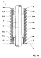
- Fig. 1a shows a conventional gas-insulated dielectric bushing 1, in particular a high voltage bushing 1 for a high voltage electrical apparatus.
- the bushing 1 comprises an insulator part 2; 2a, 2b with a first ground-side mounting flange 4 for mounting the bushing 1 on a grounded housing 5 of an electrical apparatus (not shown) and a second voltage-side mounting flange 8 for mounting the bushing 1 to a high voltage part (not shown).
- the insulator part 2; 2a, 2b has a gas space 20 for an insulating gas 20 in the interior.
- the gas space 20 contains a dielectrically insulating gas 20, e.g. As air, compressed air, nitrogen, SF 6 or similar gas.
- the gas-insulated bushing 1 is thus hollow, typically hollow cylindrical, with an axis 3a, for receiving an electrical part 3 or at least one electrical conductor 3 in the gas space 20.
- the bushing 1 is usually used to connect the encapsulated electrical apparatus to ground potential 5 at High or medium voltage network.
- an internal shielding electrode 6, 6a is necessarily present in order to achieve field relief in the field-loaded zone 7, 7a at the lower ground flange 4 and to reduce or avoid partial discharges and flashovers.
- the shielding electrode 6, 6a is typically in electrical contact 46 with the ground flange 4. It protrudes into the gas space 20 and tapers generally conically upwards.
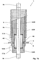
- Fig. 1b shows an example of a solid-state implementation 1 according to the prior art.
- the insulator part 2, 2b is designed as a resin body 2 filled in its entirety with an optional shield 2b.
- the insulator part 2, 2b thus has an insulation space for a solid insulating material 20 in the interior.
- 3b and 3c denote the power connections.
- the insulator part 2, 2b surrounds the current conductor 3.
- a shielding electrode 6, 6a in the field loading zone 7, 7a on the earth flange 4 is present and is electrically conductively connected thereto via a contact 46.
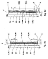
- Fig. 2a-2d and Fig. 3a-3b show exemplary embodiments of a gas-insulated or solid-insulated or otherwise insulated dielectric bushing 1 ', in accordance with the invention at least one shielding electrode 6; 6a, 6b has been omitted without sacrificing dielectric strength or reliability.
- the shielding electrode 6; 6a, 6b is namely for the purpose of field control in the field loading zone 7; 7a, 7b a nonlinear electrical and / or dielectric field control element 9; 9a, 9b; 9i, 9o; 9s on the insulator part 2; 2a, 2b; 2c in the region of the first mounting flange 4 available.
- the field control element 9; 9a, 9b; 9i, 9o; 9s is used instead of the earlier in the insulator part 2; 2a, 2b; 2c arranged shielding electrode 6; 6a, 6b for the dielectric discharge of the field loading zone 7; 7a, 7b.
- the field control element 9; 9a, 9b; 9i, 9o; 9s is used instead of the earlier in the insulator part 2; 2a, 2b; 2c arranged shielding electrode 6; 6a, 6b for the dielectric discharge of the field loading zone 7; 7a, 7b.
- the field control element 9 is designed for the purpose of relieving the field loading zone 7 in such a way that the flange region 7 is stress-relieved.
- the field control element 9 in an intermediate layer 22 between the GRP pipe (glass fiber reinforced plastic and in particular epoxy tube) 2a and the silicone shield 2b in the form of a cylinder jacket-shaped coating 9 is arranged.
- the field control element 9 may be replaced by any known manufacturing or processing process, e.g. B. casting, spraying, winding, extrusion o. ⁇ ., Be applied to the outside of the GRP pipe 2 a.
- the field control element 9; 9a, 9b; 9i, 9o; 9s on: nonlinear electrical varistor characteristics and in particular a critical field strength, the varistor switching behavior of the field control element 9; 9a, 9b; 9i, 9o; 9s characterized; and / or a high dielectric constant ⁇ , in particular ⁇ > 30, preferably ⁇ > 40 and particularly preferably ⁇ > 50.
- the field control element 9 is in electrical contact with the first mounting flange 4 and extends over a predeterminable length l along a longitudinal extension x of the insulator part 2; 2a, 2b. It has a predeterminable thickness d or thickness distribution d (l) as a function of the length l. Preferably, its length l is greater than or equal to a ratio of a maximum test voltage to be tested, in particular a lightning impulse, to the critical electric field strength. This design consideration applies with advantage for all embodiments where the shielding electrode 6a in the Erdflansch Scheme 7a by the field control element 9; 9a; 9i, 9o is replaced.
- Fig. 2b is the field control material 9, 9i disposed on an inner side 21 of the GRP pipe 2a and can additionally help to reduce surface charges there.
- the length l 1 is chosen here by way of example so that the field control layer 9, 9i is not in electrical contact with the counter flange 8.
- Fig. 2c can in addition to the field control 9; 9a another field control element 9; 9b, which likewise has suitable nonlinear electrical and / or dielectric properties, in particular those as previously described for the field control element 9; 9a, and in addition in a field loading zone 7, 7b in the region of the second mounting flange 8 over a predetermined length l; l 2 and thickness d or d (l 2 ) on the insulator part 2; 2a, 2b is present.
- the further field control element 9 is used; 9b as a replacement for a shielding electrode 6b in the region of the second, here the upper, mounting flange 8.
- the field control element 9; 9a including the further field control element 9; 9b is selected in the intermediate layer 22.
- the further field control element 9; 9b in electrical contact with the second mounting flange 8 and / or is the further field control element 9; 9b by a field control material-free zone extending along the longitudinal extent of the insulator part 2; 2a, 2b extends from the field control element 9; 9a separated in the region of the first mounting flange 4.
- a first field control element 9; 9o in the intermediate layer 22 between the GRP pipe 2a and shield 2b and a second field control element 9, 9i on the inner side 21 of the GRP pipe 2a in the Erdflansch Scheme 7a be present.
- the first integrated and the second internal field control element 9o, 9i can be made of the same or other field control material and in particular varistor material.
- the associated thicknesses d o , d i and lengths l o , l i can be designed individually. By way of example, d i > d o and l i ⁇ l o are selected.
- Fig. 3a and Fig. 3b show an insulator part 2, 2c of a porcelain hollow insulator 2c, which is equipped on the inner side 21 with the field control layer 9, 9i.
- a field control material coating 9o, z. B. in disjoint horizontal Strip 9o preferably between insulator screens 2c and in particular in the lower Erdflansch Scheme 7a, be present.
- the field control material 9; 9a, 9b; 9i, 9o be present in a coating or solid shape on an inner side 21 and / or integrated in an intermediate layer 22 between components 2a, 2b of the insulator part 2; 2a, 2b and / or on an outer side 23 of the insulator part 2; 2a, 2b; 2c is arranged.
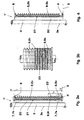
- Fig. 4 takes over the field control material 9; 9s a mechanically supporting function.
- the field control material 9; 9s in the insulator part 2; 2b the exclusive mechanical self-supporting function, so that a conventional self-supporting plastic pipe 2a can be omitted.
- Such a field control material insulator tube 2; 2b including 9s is particularly simple in construction and very thin in diameter.
- Fig. 3a and Fig. 4 on the insulator part 2; 2a, 2b; 2c over the entire surface and along a longitudinal extension x of the insulator part 2; 2a, 2b; 2c continuously and both with the first mounting flange 4; 8 as well as with the second mounting flange 8; 4 are in electrical contact.
- a preferred choice of material for the field control materials 9; 9a, 9b; 9i, 9o; 9s comprises a matrix filled with microvaristor particles and / or high dielectric constant particles.
- Suitable microvaristor particles are, for example, doped ZnO particles, TiO 2 particles or SnO 2 particles. High dielectric constant have z.
- the matrix is chosen application-specific and can, for. Example, an epoxy, silicone, EPDM, thermoplastic, thermoplastic elastomer or glass.
- the filling of the matrix with microvaristor particles may be, for example, between 20% by volume and 60% by volume.
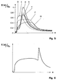
- Fig. 5 12 shows calculations of the E field distribution E (x) normalized to a maximum E field E 0 as a function of the longitudinal coordinate x of the insulator part 2 and the time represented by successive snapshots a, b, c for a conventional feedthrough 1 with shielding electrode 6 according to Fig. 1 and D, E, F, G for an inventive implementation 1 '.
- the calculations were made for a SF 6 170 kV bushing with GRP pipe 2a and silicone shield 2b according to conventional structure 1 or inventive construction 1 '.
- Fig. 5 12 shows calculations of the E field distribution E (x) normalized to a maximum E field E 0 as a function of the longitudinal coordinate x of the insulator part 2 and the time represented by successive snapshots a, b, c for a conventional feedthrough 1 with shielding electrode 6 according to Fig. 1 and D, E, F, G for an inventive implementation 1 '.
- the calculations were made for a SF 6 170 kV bushing with GRP
- the electric field strength E (x) at the silicon - air interface is shown during or shortly after the application of a lightning impulse with time delays of 0.5 ⁇ s / 2.2 ⁇ s / 20 ⁇ s for the curves a, b, c and 0.5 ⁇ s / 1.0 ⁇ s / 5 ⁇ s / 20 ⁇ s for the curves D, E, F, G. It can be clearly seen that the new design of the bushing 1 'avoids the E-field peaks and at any time produces a more homogeneous electric field. Field distribution is achieved. In addition, the areas of increased field strength are no longer stationary, which has an advantageous effect on the dielectric behavior of the bushing 1 '. With the help of the field calculations and the nonlinear electrical and / or dielectric properties of the field control element 9; 9a, 9b; 9i, 9o; 9s, the field control design of the implementation 1 'can be optimized.
- Fig. 6 shows an insufficient design, wherein the field control element 9; 9a, 9b; 9i, 9o; 9s has too high electrical conductivity or the length l; l 1 , l 2 is too short.
- the E-field propagates along the field control layer 9; 9a, 9b; 9i, 9o; 9s, but is not degraded, so that at the end of the field control layer 9; 9a, 9b; 9i, 9o; 9s nevertheless again a field exaggeration occurs, the partial discharges, rollovers or punches.
- too low electrical conductivity of the field control material 9; 9a, 9b; 9i, 9o; 9s the E-field can not be effectively controlled or controlled.
- the simple but effective rule can be stated that the field control element length l; l 1 , l 2 is greater than or equal to choose a ratio of a surge voltage to the critical electric field strength, the varistor switching behavior of the field control element 9; 9a, 9b; 9i, 9o; 9s characterized.
- a high-voltage electrical apparatus in particular a disconnector, outdoor circuit breaker, vacuum switch, dead tank breaker, current transformer, voltage transformer, transformer, power capacitor or cable termination or in an electrical switchgear for high - or medium voltage.
- the invention also relates to a high-voltage electrical apparatus, in particular a disconnector, outdoor circuit breaker, dead tank breaker, current transformer, voltage transformer, transformer, power capacitor or cable termination, in which a dielectric feedthrough 1 'is present as described above.
- an electrical switchgear in particular a high or medium voltage switchgear comprising such a high voltage electrical apparatus claimed.
Landscapes
- Engineering & Computer Science (AREA)
- Power Engineering (AREA)
- Insulators (AREA)
- Thermistors And Varistors (AREA)
Description
- Die Erfindung bezieht sich auf das Gebiet der Hoch- oder Mittelspannungstechnik, insbesondere auf elektrische Isolations- und Anschlusstechnik für geerdete Hochspannungsapparate. Sie geht aus von einer dielektrischen Durchführung und einem elektrischen Hochspannungsapparate gemäss Oberbegriff der unabhängigen Patentansprüche.
- In der
WO 02/065486 A1 - Bei Porzellanisolatoren kann die FGM-Beschichtung in Form einer Glasur oder eines Farbanstrichs aufgebracht oder in einen Brei oder in Ton gemischt, auf den Porzellanisolator aufgebracht und dort zu einer Glasur oder einer Keramikschicht gebrannt werden. Alternativ kann die Matrix für die FGM-Beschichtung ein Polymer, ein Klebstoff, eine Gussmasse oder ein Mastix oder ein Gel sein.
- In der
EP 1 042 756 wird ein glasfaserverstärktes Isolatorrohr offenbart, das auf der Innenfläche und gegebenenfalls auch Aussenfläche mit einem Harz imprägniert ist, welches einen partikelförmigen Füllstoff mit Varistoreigenschaften, insbesondere Zinkoxid, aufweist. Das GFK-Rohr kann durch Wickeln eines Glasfasernetzes hergestellt werden, das zumindest an den äusseren Schichten mit dem varistorgefüllten Harz imprägniert wird. - Im Buch "The Electric Power Engineering Handbook" von L. L. Grigsby, CRC Press und IEEE Press, Boca Raton (2001) werden im Kapitel 3.13, "Electrical Bushings" von L. B. Wagenaar, S. 3-171 bis 3-184 verschiedene Typen elektrischer Durchführungen offenbart. Insbesondere wird in
Fig. 3 .151 eine Durchführung mit einer erdseitigen, innerhalb des Isolatorrohrs angeordneten Abschirmelektrode angegeben. Durch die Abschirmelektrode wird im Bereich des erdseitigen Montageflansches eine Feldsteuerung derart erreicht, dass die stark feldbelastete Zone am Übergang von Flansch zu Isolator feldentlastet wird. Derartige innenliegende Abschirmelektroden sind in druckgasisolierten Durchführungen, z. B. in SF6-isolierten oder luftisolierten Durchführungen, insbesondere für Hochspannungsniveau zwingend vorhanden. Innenliegende Abschirmelektroden sind auch für feststoffisolierte Durchführungen bekannt. Die Abschirmelektroden führen jedoch zu grossen Durchmessern der Durchführungen. Zudem werden mit Abschirmelektroden nur relativ inhomogene Feldsteuerungen im Vergleich zu Kondensator-Durchführungen mit Öl― oder Harz-imprägniertem Papier erreicht. Dies muss durch grössere Bauhöhen für die Durchführungen kompensiert werden. - In der Broschüre von ABB Power Technology Products AB, "SF6-air bushings, type GGA", Technical Guide, 1996-03-30 werden dielektrische Durchführungen offenbart, die mit internen Abschirmelektroden am Erdflansch und für höhere Spannungsniveaus zusätzlich auch am spannungsseitigen Flansch ausgerüstet sind.
- In der
DE 198 44 409 wird ein Isolator gezeigt, der insbesondere für dielektrische Durchführungen geeignet ist. Der Isolator umfasst wie üblich einen Isolatorkörper aus Porzellan oder Verbundwerkstoff und eine Beschirmung aus Porzellan oder Silikon. Die Beschirmung weist eine variable Isolatorschirmdichte auf. Zur Feldentlastung in einem Isolatorendbereich ist wiederum die bekannte Schirmelektrode zwischen Isolatorkörper und Stromleiter vorhanden. Es wird nun vorgeschlagen, in dem stark feldbelasteten Bereich, wo die Schirmelektrode endet, eine erhöhte Anzahl von Isolatorschirmen anzubringen. Durch die erhöhte Isolatorschirmdichte wird eine verbesserte Feldentlastung im Endbereich der Schirmelektrode erreicht. - Die Erfindung nimmt auf einen Stand der Technik Bezug, wie er aus dem
U. S. Pat. No. 3,318,995 bekannt ist. Dort werden aus Giessharz gefertigte Durchführungen offenbart, die auch bei differentieller thermischer Ausdehnung oder schwundbedingter Hohlraumbildung zwischen Metall und Giessharz elektrisch betriebssicher bleiben. Für diesen Zweck werden Gebiete mit erhöhter Rissbildungstendenz durch teilweise leitfähige oder halbleitende Feldabschirmungsschichten elektrisch abgeschirmt. Die Schichten sind entweder auf dem unter Hochspannung stehenden Innenleiter angeordnet und mit diesem endseitig elektrisch verbunden; oder sie sind auf Abschirmelektroden angeordnet und mit diesen endseitig elektrisch verbunden, wobei die Abschirmungselektroden ihrerseits mit dem auf Erdpotential liegenden Gehäuse des angeschlossenen Apparats elektrisch verbunden sind. Die Feldabschirmungsschichten schaffen einen feldfreien Raum zwischen sich selbst und Innenleiter oder sich selbst und Abschirmungselektrode und schirmen dort Hohlräume im Giessharz wirkungsvoll ab. - Aufgabe der vorliegenden Erfindung ist es, eine verbesserte dielektrische Durchführung sowie einen elektrischen Hochspannungsapparat und eine elektrische Schaltanlage mit einer solchen Durchführung anzugeben. Diese Aufgabe wird erfindungsgemäss durch die Merkmale des unabhängigen Anspruchs gelöst.
- Die Erfindung besteht in einer dielektrischen Durchführung, insbesondere einer Hochspannungsdurchführung für einen elektrischen Hochspannungsapparat, umfassend einen Isolatorteil mit einem ersten Montageflansch und einem zweiten Montageflansch zur Montage der Durchführung, wobei innerhalb der Durchführung in einer Feldbelastungszone im Bereich des ersten Montageflansches eine für ein gewünschtes Spannungsniveau erforderliche Abschirmelektrode weggelassen ist und stattdessen zum Zwecke der Feldsteuerung in der Feldbelastungszone ein nichtlinear elektrisches und/oder dielektrisches Feldsteuerelement am Isolatorteil im Bereich des ersten Montageflansches vorhanden ist und das Feldsteuerelement in elektrischem Kontakt mit dem ersten Montageflansch steht.
- Durch die Erfindung kann also eine nach herkömmlichem technischen Verständnis für ein vorgebbares Spannungsniveau notwendig vorhandene Abschirmelektrode weggelassen werden. Dadurch werden vielfältige Vorteil erreicht. Durch Weglassen der bisher notwendig vorhandenen inneren Abschirmelektrode können dielektrische Durchführungen dünner, d. h. mit reduziertem Durchmesser gebaut werden. Die Grenzspannung, ab welcher eine konische Verbreiterung zum Erdflansch hin wirtschaftlicher ist, kann zu höheren Spannungsniveaus verschoben werden. Zylindrische Durchführungen sind günstiger herzustellen als konische. Die Gefahr elektrischer Überschläge zwischen benachbarten Durchführungen ist reduziert und benachbarte Phasen können räumlicher näher zueinander oder zur Erde angeordnet werden. Schliesslich wird durch die erfindungsgemässe Feldentlastung durch Feldsteuermaterial im Flanschbereich eine bessere Feldsteuerung erreicht als durch die herkömmlich verwendete Abschirmelektrode. Die Durchführungen können deshalb auch kürzer gebaut werden. Insbesondere bei Pulsbelastung wird das E-Feld nämlich nicht mehr im Bereich der Abschirmelektrode während der ganzen Pulsdauer konzentriert, sondern kann sich als Welle entlang dem Feldsteuerelement ausbreiten und dabei abbauen. Zudem sind die maximalen Feldstärken reduziert.
- In einem ersten Ausführungsbeispiel ist das Feldsteuermaterial hinsichtlich seiner nichtlinear elektrischen und/oder dielektrischen Eigenschaften, seiner geometrischen Gestalt und seiner Anordnung am Isolatorteil zur dielektrischen Entlastung der Feldbelastungszone ohne Abschirmelektrode für alle Betriebszustände, insbesondere für Stossspannungen, ausgelegt. Das Feldsteuerelement kann somit auch die kritischsten Feldbelastungszustände ohne Abschirmelektrode oder Abschirmelektroden meistern.
- In Anspruch 3 werden Designkriterien zur elektrischen Auslegung des Feldsteuermaterials angegeben, durch die eine vorteilhafte Feldsteuerung realisierbar ist.
- In Anspruch 4 und 5 werden Designkriterien zur geometrischen Auslegung des Feldsteuerelements angegeben, durch die mit wenig Materialaufwand eine vorteilhafte Feldsteuerung erreichbar ist. Insbesondere kann eine minimal erforderliche Länge des Feldsteuerelements entlang der Längsausdehnung des Isolatorteils gemäss Anspruch 5 festgelegt werden. Dadurch wird erreicht, dass sich die Feldbelastung insbesondere bei Stossspannung als Wanderwelle entlang dem Feldsteuerelement ausbreitet und dabei soweit abbaut, dass sich bei Erreichen des entfernten Endes des Feldsteuermaterials keine schädlichen Feldstärken mehr ausbilden können.
- Anspruch 6 gibt an, wie mit dem Feldsteuerelement auf einfache Weise Gleichstrom-Durchführungen gebaut werden können.
- Das Ausführungsbeispiel gemäss Anspruch 7 hat den Vorteil, dass insbesondere die höchsten Feldbelastungen im Bereich des Erdflansches mit dem Feldsteuermaterial beherrschbar sind.
- Die Ausführungsbeispiele gemäss Anspruch 8 und 9 haben den Vorteil, dass beide Flanschregionen durch die Feldsteuermaterialien unabhängig voneinander vor Überschlägen oder Teilentladungen geschützt sind.
- Anspruch 10 Merkmal a) gibt verschiedene radiale Positionen zur Anordnung des Feldsteuermaterials am Isolatorteil an. Anspruch 10 Merkmal b) hat den Vorteil, dass ein herkömmliches GFK-Rohr (glasfaserverstärkter Kunststoff) oder ein herkömmlicher Porzellanisolator durch ein selbsttragendes FGM-Rohr (Feldsteuermaterial-Rohr) ersetzbar ist.
- Anspruch 11 gibt vorteilhafte Materialkomponenten für das Feldsteuerelement an.
- Ansprüche 12 und 13 betreffen einen elektrischen Hochspannungsapparat und eine elektrische Schaltanlage umfassend eine erfindungsgemässe Durchführung mit den oben genannten Vorteilen.
- Weitere Ausführungen, Vorteile und Anwendungen der Erfindung ergeben sich aus abhängigen Ansprüchen sowie aus der nun folgenden Beschreibung und den Figuren.
-
- Fig. 1a, 1b
- zeigen im Querschnitt konventionelle Hochspannungsdurchführungen gemäss Stand der Technik;
- Fig. 2a-2d
- zeigen im Querschnitt Ausführungsformen einer FGM-Durchführung für ein GFK-Rohr mit Silikonbeschirmung und
- Fig. 2a
- einer durchgehenden FGM-Beschichtung
- Fig. 2b
- einer erdseitigen FGM-Beschichtung
- Fig. 2c
- je einer unabhängigen erdseitigen und hochspannungsseitigen FGM-Beschichtung und
- Fig. 2d
- einer innenseitigen und aussenseitigen FGMBeschichtung;
- Fig. 3a-3b
- zeigen im Querschnitt und in Draufsicht Ausführungsformen einer FGM-Durchführung für einen Porzellanisolator mit innenseitiger und optional aussenseitiger FGM-Beschichtung;
- Fig. 4
- zeigt im Querschnitt eine Ausführungsform für ein selbsttragendes Feldsteuerelement mit einer Silikonbeschirmung;
- Fig. 5
- zeigt für Blitzstosstests berechnete elektrische Oberflächen-Feldverteilungen E(x) als Funktion der Ortskoordinate x entlang der Durchführung und als Funktion der Zeit für konventionelle Durchführungen (a, b, c) und für eine erfindungsgemässe FGM-Durchführung (D, E, F, G); und
- Fig. 6
- zeigt eine unvorteilhafte Feldverteilung E(x) bei zu kurzer Länge oder zu grosser Leitfähigkeit der FGM-Beschichtung.
- In den Figuren sind gleiche Teile mit gleichen Bezugszeichen versehen.
-
Fig. 1a zeigt eine herkömmliche gasisolierte dielektrische Durchführung 1, insbesondere eine Hochspannungsdurchführung 1 für einen elektrischen Hochspannungsapparat. Die Durchführung 1 umfasst einen Isolatorteil 2; 2a, 2b mit einem ersten erdseitigen Montageflansch 4 zur Montage der Durchführung 1 an einem geerdeten Gehäuse 5 eines elektrischen Apparats (nicht dargestellt) und einen zweiten spannungsseitigen Montageflansch 8 zur Montage der Durchführung 1 an einem Hochspannungsteil (nicht dargestellt). Der Isolatorteil 2; 2a, 2b weist im Inneren einen Gasraum 20 für ein Isolationsgas 20 auf. Der Gasraum 20 enthält ein dielektrisch isolierendes Gas 20, z. B. Luft, Druckluft, Stickstoff, SF6 oder ähnliches Gas. Es kann auch ein Isolationsraum 20 zur Aufnahme einer Isolationsflüssigkeit 20 vorhanden sein. Die gasisolierte Durchführung 1 ist also hohl, typischerweise hohlzylindrisch, mit einer Achse 3a, zur Aufnahme eines elektrischen Teils 3 oder mindestens eines elektrischen Stromleiters 3 im Gasraum 20. Die Durchführung 1 dient in der Regel zum Anschluss des gekapselten elektrischen Apparats auf Erdpotential 5 an ein Hoch- oder Mittelspannungsnetz. Bekanntermassen ist eine innenliegende Abschirmelektrode 6, 6a notwendigerweise vorhanden, um in der feldbelasteten Zone 7, 7a am unteren Erdflansch 4 eine Feldentlastung zu erreichen und Teilentladungen und Überschläge zu vermindern oder zu vermeiden. Die Abschirmelektrode 6, 6a steht typischerweise in elektrischem Kontakt 46 mit dem Erdflansch 4. Sie ragt in den Gasraum 20 hinein und verjüngt sich im allgemeinen konisch nach oben. Sie bestimmt den Durchmesser der Durchführung 1 im Erdflanschbereich 4. Gestrichelt angedeutet ist eine weitere Abschirmelektrode 6, 6b, die in der feldbelasteten Zone 7, 7b am oberen spannungsseitigen Flansch 8 angeordnet sein kann. Auch diese ist oftmals konisch nach unten verjüngt und dient zur Feldsteuerung in der Feldbelastungszone 7, 7b. -
Fig. 1b zeigt ein Beispiel einer feststoffisolierten Durchführung 1 gemäss Stand der Technik. Hier ist der Isolatorteil 2, 2b als im Inneren vollvolumig gefüllter Harz-Körper 2 mit einer optionalen Beschirmung 2b ausgeführt. Der Isolatorteil 2, 2b weist also im Inneren einen Isolationsraum für ein Feststoffisolationsmaterial 20 auf. 3b und 3c bezeichnen die Stromanschlüsse. Der Isolatorteil 2, 2b umgreift den Stromleiter 3. Zur Feldsteuerung ist wiederum eine Abschirmelektrode 6, 6a in der Feldbelastungszone 7, 7a am Erdflansch 4 vorhanden und ist mit dieser über eine Kontaktierung 46 elektrisch leitend verbunden. -
Fig. 2a-2d undFig. 3a-3b zeigen Ausführungsbeispiele für eine gasisolierte oder feststoffisolierte oder anderweitige isolierte dielektrische Durchführung 1', bei der erfindungsgemäss mindestens eine Abschirmelektrode 6; 6a, 6b ohne Einbusse an dielektrischer Festigkeit oder Zuverlässigkeit weggelassen wurde. Statt der Abschirmelektrode 6; 6a, 6b ist nämlich zum Zwecke der Feldsteuerung in der Feldbelastungszone 7; 7a, 7b ein nichtlinear elektrisches und/oder dielektrisches Feldsteuerelement 9; 9a, 9b; 9i, 9o; 9s am Isolatorteil 2; 2a, 2b; 2c im Bereich des ersten Montageflansches 4 vorhanden. Das Feldsteuerelement 9; 9a, 9b; 9i, 9o; 9s dient anstelle der früher im Isolatorteil 2; 2a, 2b; 2c angeordneten Abschirmelektrode 6; 6a, 6b zur dielektrischen Entlastung der Feldbelastungszone 7; 7a, 7b. Im folgenden werden bevorzugte Ausführungsbeispiele diskutiert. - Gemäss
Fig. 2a ist das Feldsteuerelement 9 zur dielektrischen Entlastung der Feldbelastungszone 7 so ausgelegt, dass die Flanschregion 7 stressentlastet ist. Hierfür ist das Feldsteuerelement 9 in einer Zwischenschicht 22 zwischen dem GFK-Rohr (glasfaserverstärktem Kunststoff- und insbesondere Epoxy-Rohr) 2a und der Silikonbeschirmung 2b in Form einer zylindermantelförmigen Beschichtung 9 angeordnet. Insbesondere kann das Feldsteuerelement 9 durch irgendeinen bekannten Herstellungs- oder Verarbeitungsprozess, z. B. Giessen, Spritzen, Wickeln, Extrusion o. ä., auf die Aussenseite des GFK-Rohrs 2a aufgebracht sein. - Bevorzugt weist das Feldsteuerelement 9; 9a, 9b; 9i, 9o; 9s auf: nichtlinear elektrische Varistoreigenschaften und insbesondere eine kritische Feldstärke, die ein Varistor-Schaltverhalten des Feldsteuerelements 9; 9a, 9b; 9i, 9o; 9s charakterisiert; und/oder eine hohe Dielektrizitätskonstante ε, insbesondere ε>30, bevorzugt ε>40 und besonders bevorzugt ε>50.
- Mit Vorteil steht das Feldsteuerelement 9 in elektrischem Kontakt mit dem ersten Montageflansch 4 und erstreckt sich über eine vorgebbare Länge l entlang einer Längserstreckung x des Isolatorteils 2; 2a, 2b. Es weist eine vorgebbare Dicke d oder Dickenverteilung d(l) als Funktion der Länge l auf. Bevorzugt ist seine Länge l grösser oder gleich einem Verhältnis einer maximalen zu prüfenden Stossspannung, insbesondere einer Blitzstossspannung, zu der kritischen elektrischen Feldstärke. Diese Designüberlegung gilt mit Vorteil für alle Ausführungsbeispiele, wo die Abschirmelektrode 6a im Erdflanschbereich 7a durch das Feldsteuerelement 9; 9a; 9i, 9o ersetzt ist.
- Gemäss
Fig. 2b ist das Feldsteuermaterial 9, 9i auf einer Innenseite 21 des GFK-Rohrs 2a angeordnet und kann dort zusätzlich auch Oberflächenladungen abzubauen helfen. Die Länge l1 ist hier beispielhaft so gewählt, dass die Feldsteuerschicht 9, 9i nicht in elektrischem Kontakt mit dem Gegenflansch 8 steht. - Gemäss
Fig. 2c kann neben dem Feldsteuerelement 9; 9a ein weiteres Feldsteuerelement 9; 9b vorhanden sein, das ebenfalls geeignete nichtlinear elektrische und/oder dielektrische Eigenschaften, insbesondere solche wie zuvor für das Feldsteuerelement 9; 9a beschrieben, aufweist und das zusätzlich in einer Feldbelastungszone 7, 7b im Bereich des zweiten Montageflansches 8 über eine vorgebbare Länge l; l2 und Dicke d oder d(l2) am Isolatorteil 2; 2a, 2b vorhanden ist. Insbesondere dient das weitere Feldsteuerelement 9; 9b als Ersatz für eine Abschirmelektrode 6b im Bereich des zweiten, hier des oberen, Montageflansches 8. Hier ist beispielhaft wieder eine Anordnung des Feldsteuerelements 9; 9a inklusive des weiteren Feldsteuerelements 9; 9b in der Zwischenschicht 22 gewählt. Bevorzugt steht das weitere Feldsteuerelement 9; 9b in elektrischem Kontakt mit dem zweiten Montageflansch 8 und/oder ist das weitere Feldsteuerelement 9; 9b durch eine feldsteuermaterialfreie Zone, die sich entlang der Längserstreckung des Isolatorteils 2; 2a, 2b erstreckt, vom Feldsteuerelement 9; 9a im Bereich des ersten Montageflansches 4 getrennt. - Gemäss
Fig. 2d kann zugleich ein erstes Feldsteuerelement 9; 9o in der Zwischenschicht 22 zwischen GFK-Rohr 2a und Beschirmung 2b und ein zweites Feldsteuerelement 9, 9i auf der Innenseite 21 des GFK-Rohrs 2a im Erdflanschbereich 7a vorhanden sein. Dadurch wird eine weiter verbesserte Feldsteuerung erreicht. Das erste integrierte und das zweite innenliegende Feldsteuerelement 9o, 9i können aus gleichem oder anderem Feldsteuermaterial und insbesondere Varistormaterial hergestellt sein. Die zugehörigen Dicken do, di und Längen lo, li können individuell ausgelegt sein. Beispielhaft ist di > do und li < lo gewählt. -
Fig. 3a und Fig. 3b zeigen ein Isolatorteil 2, 2c aus einem Porzellan-Hohlisolator 2c, der auf der Innenseite 21 mit der Feldsteuerschicht 9, 9i ausgestattet ist. Optional kann zusätzlich auch auf der Aussenseite 23 eine Feldsteuermaterialbeschichtung 9o, z. B. in disjunkten horizontalen Streifen 9o, bevorzugt zwischen Isolatorschirmen 2c und insbesondere im unteren Erdflanschbereich 7a, vorhanden sein. Insgesamt kann also das Feldsteuermaterial 9; 9a, 9b; 9i, 9o in einer Beschichtung oder auch massiven Gestalt vorhanden sein, die auf einer Innenseite 21 und/oder integriert in einer Zwischenschicht 22 zwischen Bestandteilen 2a, 2b des Isolatorteils 2; 2a, 2b und/oder auf einer Aussenseite 23 des Isolatorteils 2; 2a, 2b; 2c angeordnet ist. - Gemäss
Fig. 4 übernimmt das Feldsteuermaterial 9; 9s eine mechanisch tragende Funktion. Bevorzugt übernimmt das Feldsteuermaterial 9; 9s im Isolatorteil 2; 2b die ausschliessliche mechanisch selbsttragende Funktion, so dass ein herkömmliches selbsttragendes Kunststoffrohr 2a entfallen kann. Ein solches Feldsteuermaterial-Isolatorrohr 2; 2b inklusive 9s ist besonders einfach im Aufbau und besonders dünn im Durchmesser. - Für Gleichstromanwendungen soll das Feldsteuerelement 9; 9i, 9s gemäss
Fig. 2a ,Fig. 3a und Fig. 4 am Isolatorteil 2; 2a, 2b; 2c vollflächig und entlang einer Längserstreckung x des Isolatorteils 2; 2a, 2b; 2c durchgehend vorhanden sein und sowohl mit dem ersten Montageflansch 4; 8 als auch mit dem zweiten Montageflansch 8; 4 in elektrischem Kontakt stehen. - Eine bevorzugte Materialwahl für die Feldsteuermaterialien 9; 9a, 9b; 9i, 9o; 9s umfasst eine Matrix, die mit Mikrovaristorpartikeln und/oder Partikeln hoher Dielektrizitätskonstante gefüllt ist. Als Mikrovaristorpartikel kommen beispielsweise dotierte ZnO-Partikel, TiO2-Partikel oder SnO2-Partikel in Frage. Hohe Dielektrizitätskonstante weisen z. B. BaTiO3-Partikel oder TiO2-Partikel auf. Im Falle von ZnO-Mikrovaristorpartikeln werden diese typischerweise in einem Temperaturbereich von 800 °C bis 1200 °C gesintert. Nach einem Aufbrechen und gegebenenfalls Sieben des Sinterprodukts weisen die Mikrovaristorpartikel eine typische Teilchengrösse von kleiner als 125 µm auf. Die Matrix wird anwendungsspezifisch gewählt und kann z. B. ein Epoxy, Silikon, EPDM, Thermoplast, thermoplastisches Elastomer oder Glas umfassen. Die Befüllung der Matrix mit Mikrovaristorpartikeln kann beispielsweise zwischen 20 Volumen% und 60 Volumen% betragen.
-
Fig. 5 zeigt Berechnungen der E-Feldverteilung E(x), normiert auf ein maximales E-Feld E0, als Funktion der Längenortskoordinate x des Isolatorteils 2 und der Zeit, dargestellt durch sukzessive Momentaufnahmen a, b, c für eine herkömmliche Durchführung 1 mit Abschirmelektrode 6 gemässFig. 1 und D, E, F, G für eine erfindungsgemässe Durchführung 1'. Die Berechnungen wurden für eine SF6 170 kV Durchführung mit GFK-Rohr 2a und Silikonbeschirmung 2b gemäss herkömmlichem Aufbau 1 oder erfindungsgemässem Aufbau 1' gemacht. InFig. 5 ist die elektrische Feldstärke E(x) an der Grenzfläche Silikon - Luft während oder kurz nach Anlegen einer Blitzstossspannung dargestellt, mit Zeitverzögerungen von 0,5 µs / 2,2 µs / 20 µs für die Kurven a, b, c und 0,5 µs / 1,0 µs / 5 µs / 20 µs für die Kurven D, E, F, G. Man erkennt deutlich, dass durch das neue Design der Durchführung 1' die E-Feldspitzen vermieden werden und zu jedem Zeitpunkt eine homogenere E-Feldverteilung erreicht wird. Zudem sind die Bereiche erhöhter Feldstärke nicht mehr ortsfest, was sich vorteilhaft auf das dielektrische Verhalten der Durchführung 1' auswirkt. Mit Hilfe der Feldberechnungen und der nichtlinear elektrischen und/oder dielektrischen Eigenschaften des Feldsteuerelements 9; 9a, 9b; 9i, 9o; 9s kann das Feldsteuerungs-Design der Durchführung 1' optimiert werden. -
Fig. 6 zeigt eine ungenügende Auslegung, wobei das Feldsteuerelement 9; 9a, 9b; 9i, 9o; 9s eine zu hohe elektrische Leitfähigkeit aufweist oder die Länge l; l1, l2 zu kurz gewählt ist. Dadurch breitet sich das E-Feld entlang der Feldsteuerschicht 9; 9a, 9b; 9i, 9o; 9s aus, wird dabei aber nicht abgebaut, so dass am Ende der Feldsteuerschicht 9; 9a, 9b; 9i, 9o; 9s gleichwohl wieder eine Feldüberhöhung auftritt, die zu Teilentladungen, Überschlägen oder Durchschlägen führen kann. Wird andererseits eine zu niedrige elektrische Leitfähigkeit des Feldsteuermaterials 9; 9a, 9b; 9i, 9o; 9s gewählt, so kann das E-Feld nicht effektiv kontrolliert oder gesteuert werden. Für eine optimale Auslegung eines varistorartigen Feldsteuerelements 9; 9a; 9i, 9o; 9s im Erdflanschbereich 7, 7a kann die einfache, aber wirkungsvolle Regel angegeben werden, dass die Feldsteuerelementlänge l; l1, l2 grösser oder gleich einem Verhältnis einer Stossspannung zu der kritischen elektrischen Feldstärke zu wählen ist, die das Varistor-Schaltverhalten des Feldsteuerelements 9; 9a, 9b; 9i, 9o; 9s charakterisiert. - Verwendungen der erfindungsgemässen dielektrischen Durchführung 1' betreffen u.a. den Einsatz als Durchführung 1' in einem elektrischen Hochspannungsapparat, insbesondere einem Trenner, Freiluft-Leistungsschalter, Vakuumschalter, Dead Tank Breaker, Stromwandler, Spannungswandler, Transformator, Leistungskondensator oder Kabelendverschluss oder in einer elektrischen Schaltanlage für Hoch- oder Mittelspannung. Gegenstand der Erfindung ist auch ein elektrischer Hochspannungsapparat, insbesondere ein Trenner, Freiluft-Leistungsschalter, Dead Tank Breaker, Stromwandler, Spannungswandler, Transformator, Leistungskondensator oder Kabelendverschluss, bei dem eine dielektrische Durchführung 1' wie zuvor beschrieben vorhanden ist. Ebenso wird eine elektrische Schaltanlage, insbesondere eine Hoch- oder Mittelspannungsschaltanlage, umfassend einen solchen elektrischen Hochspannungsapparat beansprucht.
-
- 1
- Konventionelle Hochspannungsdurchführung
- 1'
- FGM-Hochspannungsdurchführung
- 2
- Selbsttragender Isolator
- 20
- Isolation (fest, flüssig, gelartig, gasförmig), Epoxy, Schaumstoff, Öl, Luft, SF6
- 21
- Innenseite des Isolatorteils
- 22
- Zwischenschicht des Isolatorteils
- 23
- Aussenseite des Isolatorteils
- 2a
- GFK-Rohr (glasfaserverstärkter Kunststoff), glasfaserverstärktes Epoxy-Rohr
- 2b
- Aussenisolator, Beschirmung, Silikon-Beschirmung
- 2c
- Porzellanisolator
- 3
- Stromleiter (auf Hochspannungspotential)
- 3a
- Mittelachse
- 3b
- Stromanschluss
- 3c
- Stromanschluss
- 4
- Flansch (geerdet), Erdflansch
- 46
- Kontaktierung zwischen Flansch und Abschirmelektrode
- 5
- Gehäuse von Hochspannungsapparat
- 6
- Abschirmelektrode
- 6a
- Abschirmelektrode, Erdungselektrode
- 6b
- Abschirmelektrode, Hochspannungselektrode
- 7
- Stark feldbelastete Zone
- 7a
- Feldbelastungszone im Erdflanschbereich
- 7b
- Feldbelastungszone im Hochspannungsflanschbereich
- 8
- Hochspannungsflansch
- 9
- Feldsteuerndes Material, FGM, Varistormaterial, feldsteuernde Beschichtung
- 9a
- FGM im Erdflanschbereich
- 9b
- FGM im Hochspannungsflanschbereich
- 9i
- FGM auf Isolator-Innenfläche
- 9o
- FGM auf Isolator-Aussenfläche
- 9s
- selbsttragendes feldsteuerndes Isolatorrohr
- a
- konventionelle Durchführung, nach 0,5 µs
- b
- konventionelle Durchführung, nach 2,2 µs
- c
- konventionelle Durchführung, nach 20 µs
- D
- FGM-Durchführung, nach 0,5 µs
- E
- FGM-Durchführung, nach 1,0 µs
- F
- FGM-Durchführung, nach 5 µs
- G
- FGM-Durchführung, nach 20 µs
- d, d(l)
- Dicke der feldsteuernden Beschichtung oder des feldsteuernden Rohrs
- di, do
- Dicke der feldsteuernden Innenschicht oder Aussenschicht
- l
- Länge der feldsteuernden Beschichtung oder des feldsteuernden Rohrs
- l1, l2
- Länge der feldsteuernden Beschichtung im Erdflanschbereich oder Hochspannungsflanschbereich
- E(x)
- elektrische Feldverteilung entlang Hochspannungsdurchführung
- Eo
- maximales elektrisches Feld, Normierungsfeld
- x
- Ortskoordinate entlang Längserstreckung der FGMDurchführung
Claims (13)
- Dielektrische Durchführung (1'), insbesondere Hochspannungsdurchführung (1') für einen elektrischen Hochspannungsapparat, umfassend einen Isolatorteil (2; 2a, 2b; 2c) mit einem ersten Montageflansch (4) und einem zweiten Montageflansch (8) zur Montage der Durchführung (1'), dadurch gekennzeichnet, dassa) innerhalb der Durchführung (1') in einer Feldbelastungszone (7; 7a, 7b) im Bereich des ersten Montageflansches (4; 8) eine für ein gewünschtes Spannungsniveau erforderliche Abschirmelektrode (6; 6a, 6b) weggelassen ist,b) stattdessen zum Zwecke der Feldsteuerung in der Feldbelastungszone (7; 7a, 7b) ein nichtlinear elektrisches und/oder dielektrisches Feldsteuerelement (9; 9a, 9b; 9i, 9o; 9s) am Isolatorteil (2; 2a, 2b; 2c) im Bereich des ersten Montageflansches (4) vorhanden ist undc) das Feldsteuerelement (9; 9a, 9b; 9i, 9o; 9s) in elektrischem Kontakt mit dem ersten Montageflansch (4) steht.
- Die Durchführung (1') nach Anspruch 1, dadurch gekennzeichnet, dass das Feldsteuerelement (9; 9a, 9b; 9i, 9o; 9s) hinsichtlich seiner nichtlinear elektrischen und/oder dielektrischen Eigenschaften, seiner geometrischen Gestalt und seiner Anordnung am Isolatorteil (2; 2a, 2b; 2c) zur dielektrischen Entlastung der Feldbelastungszone (7; 7a, 7b) ohne Abschirmelektrode (6; 6a, 6b) für alle Betriebszustände, insbesondere für Stossspannungen, ausgelegt ist.
- Die Durchführung (1') nach einem der vorangehenden Ansprüche, dadurch gekennzeichnet, dass das Feldsteuerelement (9; 9a, 9b; 9i, 9o; 9s) aufweist:a) nichtlinear elektrische Varistoreigenschaften und insbesondere eine kritische Feldstärke, die ein Varistor-Schaltverhalten des Feldsteuerelements (9; 9a, 9b; 9i, 9o; 9s) charakterisiert, und/oderb) eine hohe Dielektrizitätskonstante ε, insbesondere ε>30, bevorzugt ε>40 und besonders bevorzugt ε>50.
- Die Durchführung (1') nach einem der vorangehenden Ansprüche, dadurch gekennzeichnet, dass das Feldsteuerelement (9; 9a, 9b; 9i, 9o; 9s) sich über eine vorgebbare Länge (l; l1, l2) entlang einer Längserstrekkung (x) des Isolatorteils (2; 2a, 2b; 2c) erstreckt und eine vorgebbare Dicke (d) oder Dickenverteilung (d(1)) als Funktion der Länge (l; l1, l2) aufweist.
- Die Durchführung (1') nach Anspruch 3, Merkmal a) 3 und 4, dadurch gekennzeichnet, dass die Länge (l; l1, l2) grösser oder gleich einem Verhältnis einer maximalen zu prüfenden Stossspannung zu der kritischen elektrischen Feldstärke gewählt ist.
- Die Durchführung (1') nach Anspruch 3, Merkmal a) 3 oder 4, abhängig von Anspruch 3, Merkmal a) dadurch gekennzeichnet, dass das Feldsteuerelement (9; 9i, 9s) für Gleichstromanwendungen am Isolatorteil (2; 2a, 2b; 2c) vollflächig und entlang einer Längserstreckung (x) des Isolatorteils (2; 2a, 2b; 2c) durchgehend vorhanden ist und sowohl mit dem ersten Montageflansch (4) als auch mit dem zweiten Montageflansch (8) in elektrischem Kontakt steht.
- Die Durchführung (1') nach einem der vorangehenden Ansprüche, dadurch gekennzeichnet, dassa) der erste Montageflansch (4) ein endseitiger Montageflansch (4) zur Montage der Durchführung (1') an einem geerdeten Gehäuse (5) eines elektrischen Apparats ist und/oderb) der zweite Montageflansch (8) ein spannungsseitiger Montageflansch (8) zur Montage der Durchführung (1') an einem Hochspannungsteil ist und/oderc) der Isolatorteil (2; 2a, 2b; 2c) im Inneren einen Isolationsraum für ein Feststoffisolationsmaterial (20) oder für eine Isolationsflüssigkeit (20) oder einen Gasraum für ein Isolationsgas (20) aufweist.
- Die Durchführung (1') nach Anspruch 7, Merkmal a) und Anspruch 7, Merkmal b), dadurch gekennzeichnet, dassa) ein weiteres Feldsteuerelement (9; 9b) vorhanden ist, das geeignete nichtlinear elektrische und/oder dielektrische Eigenschaften, insbesondere solche gemäss Anspruch 3, aufweist und in einer Feldbelastungszone (7; 7a, 7b) im Bereich des zweiten Montageflansches (8) über eine vorgebbare Länge (l, l2) und Dicke (d, d(l2)) am Isolatorteil (2; 2a, 2b; 2c) angeordnet ist undb) insbesondere dass das weitere Feldsteuerelement (9; 9b) als Ersatz für eine Abschirmelektrode (6b) im Bereich des zweiten Montageflansches (8) dient.
- Die Durchführung (1') nach Anspruch 8, dadurch gekennzeichnet, dassa) das weitere Feldsteuerelement (9; 9b) in elektrischem Kontakt mit dem zweiten Montageflansch (8; 4) steht und/oderb) das weitere Feldsteuerelement (9; 9b) durch eine feldsteuermaterialfreie Zone, die sich entlang der Längserstreckung des Isolatorteils (2; 2a, 2b) erstreckt, vom Feldsteuerelement (9; 9a; 9i, 9o) im Bereich des ersten Montageflansches (4) getrennt ist.
- Die Durchführung (1') nach einem der vorangehenden Ansprüche, dadurch gekennzeichnet, dassa) das Feldsteuerelement (9; 9a, 9b; 9i, 9o; 9s) in einer Beschichtung oder massiven Gestalt vorhanden ist, die auf einer Innenseite (21) und/oder in einer Zwischenschicht (22) integriert zwischen Bestandteilen (2a, 2b) des Isolatorteils (2; 2a, 2b) und/oder auf einer Aussenseite (23), insbesondere dort in disjunkten horizontalen Streifen (9o), des Isolatorteils (2; 2a, 2b; 2c) vorhanden ist und/oderb) das Feldsteuerelement (9; 9a, 9b; 9i, 9o; 9s) eine mechanisch tragende Funktion übernimmt und insbesondere dass das Feldsteuermaterial (9; 9a, 9b; 9i, 9o; 9s) im Isolatorteil (2; 2a, 2b; 2c) die ausschliessliche mechanisch selbsttragende Funktion übernimmt.
- Die Durchführung (1') nach einem der vorangehenden Ansprüche, dadurch gekennzeichnet, dass das Feldsteuerelement (9; 9a, 9b; 9i, 9o; 9s) eine Matrix, insbesondere ein Epoxy, Silikon, EPDM, Thermoplast, thermoplastisches Elastomer oder Glas, umfasst und die Matrixa) mit Mikrovaristorpartikeln, insbesondere dotierten ZnO-Partikeln, TiO2-Partikeln oder SnO2-Partikeln, gefüllt ist und/oderb) mit Partikeln mit hoher Dielektrizitätskonstante, insbesondere mit BaTiO3-Partikeln oder TiO2-Partikeln, gefüllt ist.
- Elektrischer Hochspannungsapparat, insbesondere Trenner, Freiluft-Leistungsschalter, Vakuumschalter, Dead Tank Breaker, Stromwandler, Spannungswandler, Transformator, Leistungskondensator oder Kabelendverschluss, dadurch gekennzeichnet, dass eine dielektrische Durchführung (1') gemäss einem der vorangehenden Ansprüche vorhanden ist.
- Elektrische Schaltanlage, insbesondere Hoch- oder Mittelspannungsschaltanlage, gekennzeichnet durch einen elektrischen Hochspannungsapparat nach Anspruch 12.
Priority Applications (3)
| Application Number | Priority Date | Filing Date | Title |
|---|---|---|---|
| AT04405151T ATE546818T1 (de) | 2004-03-15 | 2004-03-15 | Hochspannungsdurchführung mit feldsteuermaterial |
| EP04405151A EP1577904B1 (de) | 2004-03-15 | 2004-03-15 | Hochspannungsdurchführung mit Feldsteuermaterial |
| US11/079,858 US7262367B2 (en) | 2004-03-15 | 2005-03-15 | High voltage bushing with field control material |
Applications Claiming Priority (1)
| Application Number | Priority Date | Filing Date | Title |
|---|---|---|---|
| EP04405151A EP1577904B1 (de) | 2004-03-15 | 2004-03-15 | Hochspannungsdurchführung mit Feldsteuermaterial |
Publications (2)
| Publication Number | Publication Date |
|---|---|
| EP1577904A1 EP1577904A1 (de) | 2005-09-21 |
| EP1577904B1 true EP1577904B1 (de) | 2012-02-22 |
Family
ID=34833824
Family Applications (1)
| Application Number | Title | Priority Date | Filing Date |
|---|---|---|---|
| EP04405151A Expired - Lifetime EP1577904B1 (de) | 2004-03-15 | 2004-03-15 | Hochspannungsdurchführung mit Feldsteuermaterial |
Country Status (3)
| Country | Link |
|---|---|
| US (1) | US7262367B2 (de) |
| EP (1) | EP1577904B1 (de) |
| AT (1) | ATE546818T1 (de) |
Cited By (1)
| Publication number | Priority date | Publication date | Assignee | Title |
|---|---|---|---|---|
| CN106199117A (zh) * | 2016-07-15 | 2016-12-07 | 中国南方电网有限责任公司超高压输电公司检修试验中心 | 一种直流分压器辅助伞裙设计方法 |
Families Citing this family (43)
| Publication number | Priority date | Publication date | Assignee | Title |
|---|---|---|---|---|
| SE526713C2 (sv) * | 2003-07-11 | 2005-10-25 | Abb Research Ltd | Genomföring samt förfarande för tillverkning av genomföringen |
| EP1736998A1 (de) * | 2005-06-21 | 2006-12-27 | Abb Research Ltd. | Band mit Varistor-Verhalten zur Steuerung eines elektischen Feldes |
| EP1811626B1 (de) * | 2006-01-24 | 2016-04-13 | Nexans | Elektrische Durchführung |
| DE102006038221B4 (de) * | 2006-08-03 | 2009-03-26 | Siemens Ag | Vorrichtung zur elektrischen Abschirmung einer Hochspannungsdurchführung |
| CN101136270B (zh) | 2006-08-31 | 2013-03-20 | Abb技术有限公司 | 高压套管及其制造方法以及高压设备 |
| CN101506911B (zh) * | 2006-08-31 | 2011-04-06 | Abb技术有限公司 | 高压套管 |
| US20080157783A1 (en) * | 2007-01-01 | 2008-07-03 | Maxwell Technologies, Inc. | Apparatus and method for monitoring high voltage capacitors |
| SE531321C2 (sv) * | 2007-07-05 | 2009-02-24 | Abb Technology Ag | Högspänningskabelanslutning |
| DE102007033705B4 (de) * | 2007-07-17 | 2009-03-05 | Siemens Ag | Wandleranordnung einer metallgekapselten, gasisolierten Schaltanlage sowie metallgekapselte, gasisolierte Schaltanlage |
| EP2039496A1 (de) * | 2007-09-20 | 2009-03-25 | ABB Research Ltd. | Verfahren zur Herstellung eines Gummiprodukts |
| EP2053616A1 (de) * | 2007-10-26 | 2009-04-29 | ABB Research Ltd. | Hochspannungs-Freiluftdurchführung |
| US7807930B1 (en) * | 2007-11-30 | 2010-10-05 | The United States Of America As Represented By The Secretary Of The Navy | High-voltage feed-through bushing with internal and external electric field grading elements |
| DE102008009333A1 (de) | 2008-02-14 | 2009-08-20 | Lapp Insulator Gmbh & Co. Kg | Feldgesteuerter Verbundisolator |
| EP2154700A1 (de) * | 2008-08-14 | 2010-02-17 | ABB Technology AG | Hochspannungsisolator mit Feldsteuerelement |
| EP2276041B1 (de) * | 2009-07-15 | 2013-09-25 | ABB Research Ltd. | Vorrichtung für eine elektrische Verbindung und elektrische Anlage |
| CN101714446A (zh) * | 2009-09-10 | 2010-05-26 | 北京天威瑞恒高压套管有限公司 | 玻璃钢电容式多芯变压器套管 |
| CN105207130B (zh) | 2009-09-14 | 2018-11-23 | 阿雷沃国际公司 | 地下模块化高压直流电力传输系统 |
| US8525526B2 (en) * | 2009-11-13 | 2013-09-03 | Hubbell Incorporated | High voltage test terminal having a shock-absorbing insulator |
| EP2375423A1 (de) * | 2010-04-07 | 2011-10-12 | ABB Research Ltd. | Elektrische Durchführung |
| CN102906955B (zh) | 2010-05-21 | 2015-09-23 | Abb研究有限公司 | 高压直流电缆终端装置 |
| CA2799592C (en) | 2010-05-21 | 2016-07-05 | Abb Research Ltd | A high voltage direct current cable termination apparatus |
| WO2011144253A2 (en) | 2010-05-21 | 2011-11-24 | Abb Research Ltd | A high voltage direct current cable termination apparatus |
| CA2799770C (en) | 2010-05-21 | 2017-03-14 | Abb Research Ltd | A high voltage direct current cable termination apparatus |
| EP2431982B1 (de) * | 2010-09-21 | 2014-11-26 | ABB Technology AG | Steckbare Durchführung und Hochspannungsanlage mit einer solchen Durchführung |
| DE102010043990A1 (de) * | 2010-11-16 | 2012-05-16 | Siemens Aktiengesellschaft | Isolatoranordnung sowie Verfahren zur Herstellung einer Isolatoranordnung |
| DE102010043995A1 (de) * | 2010-11-16 | 2012-05-16 | Siemens Aktiengesellschaft | Isolatoranordnung sowie Verfahren zur Herstellung einer Isolatoranordnung |
| EP2482290B1 (de) * | 2011-01-28 | 2017-07-19 | ABB Schweiz AG | Temperaturkompensierte Durchführungsanordung |
| RU2457564C1 (ru) * | 2011-02-21 | 2012-07-27 | Российская Федерация, от имени которой выступает Государственная корпорация по атомной энергии "Росатом" (Госкорпорация "Росатом") | Переход высоковольтный |
| US8704097B2 (en) * | 2012-01-23 | 2014-04-22 | General Electric Company | High voltage bushing assembly |
| US8716601B2 (en) | 2012-02-08 | 2014-05-06 | General Electric Company | Corona resistant high voltage bushing assembly |
| DE102012104137A1 (de) * | 2012-05-11 | 2013-11-14 | Maschinenfabrik Reinhausen Gmbh | Feldgesteuerter Verbundisolator |
| US9078346B2 (en) * | 2013-03-11 | 2015-07-07 | Varian Semiconductor Equipment Associates, Inc. | Insulator protection |
| DE102013204706A1 (de) * | 2013-03-18 | 2014-09-18 | Siemens Aktiengesellschaft | Widerstandsbelag für ein Gleichstromisoliersystem |
| DE102014004284B4 (de) * | 2014-03-26 | 2019-11-14 | Lapp Insulators Gmbh | Hochspannungsdurchführung |
| CN103971861A (zh) * | 2014-05-21 | 2014-08-06 | 北京铁道工程机电技术研究所有限公司 | 一种具有防界面击穿的动车车顶复合绝缘子 |
| KR101983487B1 (ko) * | 2015-03-30 | 2019-05-28 | 미츠비시 히타치 쓰루 가부시키가이샤 | 드릴 |
| EP3096334B1 (de) * | 2015-05-22 | 2020-12-30 | ABB Power Grids Switzerland AG | Elektrische durchführung |
| DE102017212977A1 (de) * | 2017-07-27 | 2019-01-31 | Siemens Aktiengesellschaft | Steckbare Hochspannungsdurchführung und elektrisches Gerät mit der steckbaren Hochspannungsdurchführung |
| CN107800109A (zh) * | 2017-10-31 | 2018-03-13 | 清华大学 | 采用非线性电导材料预制橡胶压控管的电缆端头 |
| EP3591672B1 (de) * | 2018-07-02 | 2023-03-29 | Hitachi Energy Switzerland AG | Isolator mit widerstandsgradient |
| EP3667684B1 (de) * | 2018-12-12 | 2024-08-21 | Hitachi Energy Ltd | Elektrische durchführung |
| CN113450948A (zh) * | 2021-07-19 | 2021-09-28 | 上海甲希科技有限公司 | 一种绝缘管型母线及绝缘管型母线的绝缘制造方法和设备 |
| DE102022206149A1 (de) * | 2022-06-21 | 2023-12-21 | Siemens Energy Global GmbH & Co. KG | Durchführungsisolator |
Family Cites Families (13)
| Publication number | Priority date | Publication date | Assignee | Title |
|---|---|---|---|---|
| US1484051A (en) * | 1919-04-10 | 1924-02-19 | Ohio Brass Co | Insulator |
| GB842039A (en) * | 1957-04-06 | 1960-07-20 | Asea Ab | High voltage devices comprising a potential gradient equalizing coating |
| FR1378902A (fr) * | 1963-08-20 | 1964-11-20 | Comp Generale Electricite | Procédé de fabrication d'un barreau d'ancrage à haute résistance mécanique et électrique et barreau ainsi obtenu |
| US3318995A (en) | 1966-04-25 | 1967-05-09 | Westinghouse Electric Corp | Cast electrical bushing construction having controlled and shielded shrinkage voids |
| FR2198231B1 (de) * | 1972-09-04 | 1980-02-22 | Ceraver | |
| SE429907B (sv) * | 1978-09-13 | 1983-10-03 | Asea Ab | Elektrisk hogspenningsgenomforing for ett metallkapslat, tryckgasisolerat stellverk |
| US4905118A (en) * | 1988-03-31 | 1990-02-27 | Hubbell Incorporated | Base mounted electrical assembly |
| US5214249A (en) * | 1991-02-22 | 1993-05-25 | Hubbell Incorporated | Electrical assembly with end collars for coupling ends of a weathershed housing to the end fittings |
| SE9704824D0 (sv) | 1997-12-22 | 1997-12-22 | Asea Brown Boveri | Fiberkompositföremål och metod för att framställa sådant fiberkompositföremål |
| DE19844409C2 (de) | 1998-09-28 | 2000-12-21 | Hochspannungsgeraete Porz Gmbh | Hochspannungs-Durchführung |
| DE19856123C2 (de) * | 1998-12-04 | 2000-12-07 | Siemens Ag | Hohlisolator |
| GB0103255D0 (en) * | 2001-02-09 | 2001-03-28 | Tyco Electronics Raychem Gmbh | Insulator arrangement |
| US6441310B1 (en) * | 2001-03-30 | 2002-08-27 | Hubbell Incorporated | Moisture activated barrier for electrical assemblies |
-
2004
- 2004-03-15 EP EP04405151A patent/EP1577904B1/de not_active Expired - Lifetime
- 2004-03-15 AT AT04405151T patent/ATE546818T1/de active
-
2005
- 2005-03-15 US US11/079,858 patent/US7262367B2/en not_active Expired - Lifetime
Cited By (2)
| Publication number | Priority date | Publication date | Assignee | Title |
|---|---|---|---|---|
| CN106199117A (zh) * | 2016-07-15 | 2016-12-07 | 中国南方电网有限责任公司超高压输电公司检修试验中心 | 一种直流分压器辅助伞裙设计方法 |
| CN106199117B (zh) * | 2016-07-15 | 2018-11-23 | 中国南方电网有限责任公司超高压输电公司检修试验中心 | 一种直流分压器辅助伞裙设计方法 |
Also Published As
| Publication number | Publication date |
|---|---|
| ATE546818T1 (de) | 2012-03-15 |
| EP1577904A1 (de) | 2005-09-21 |
| US7262367B2 (en) | 2007-08-28 |
| US20050199418A1 (en) | 2005-09-15 |
Similar Documents
| Publication | Publication Date | Title |
|---|---|---|
| EP1577904B1 (de) | Hochspannungsdurchführung mit Feldsteuermaterial | |
| EP3807920B1 (de) | Vakuumschaltröhre und hochspannungsschaltanordnung | |
| EP1254497B1 (de) | Kabelendverschluss | |
| EP2702597B1 (de) | Überspannungsableiter | |
| EP0176665A2 (de) | Vollfeststoffisolierter Vakuumschalter | |
| EP0874430A2 (de) | Funkenstrecke | |
| DE102021207962A1 (de) | Vakuumschaltröhre und Anordnung mit Vakuumschaltröhren sowie Verfahren zum Absteuern von Vakuumschaltröhren | |
| EP1569255B1 (de) | Kompaktes Erderschaltgerät für gasisolierte Schaltanlagen | |
| DE2934805C2 (de) | Elektrische Hochspannungsdurchführung | |
| EP3472847A1 (de) | Isolatoranordnung für eine hoch- oder mittelspannungsschaltanlage | |
| EP2715743A1 (de) | Elektrische komponente für eine hochspannungsanlage | |
| DE19500849A1 (de) | Elektrisches Bauteil | |
| WO2023147967A1 (de) | Steuerbare vakuumschaltröhre und anordnung sowie verfahren zum absteuern von vakuumschaltröhren | |
| EP1603141B1 (de) | Gasisolierter Überspannungsableiter | |
| DE68927533T2 (de) | Trenner für gasisolierte Schaltanlage | |
| EP4197073A1 (de) | Beschichteter leiter in einem hochspannungsgerät und verfahren zur erhöhung der dielektrischen festigkeit | |
| DE4007335A1 (de) | Elektrischer isolator | |
| WO2017012740A1 (de) | Energietechnische komponente, insbesondere vakuumschaltröhre | |
| DE2912844A1 (de) | Blitzschutzvorrichtung | |
| EP3266085B1 (de) | Feldsteuerelement für endverschlüsse von kabeln zu energieübertragung | |
| EP4244879A1 (de) | Elektrische schaltvorrichtung für mittel- und/oder hochspannungsanwendungen | |
| EP0658271A1 (de) | Stromwandler. | |
| WO2001041273A1 (de) | Durchführungsstützer und -stromwandler für metallgekapselte luftisolierte mittelspannungs-schaltanlagen | |
| DE2348136B2 (de) | Elektrisches geraet fuer hochspannung mit einer ein isoliergas enthaltenden kapselung aus metall | |
| DE102005060908A1 (de) | Elektrisches Schaltgerät, insbesondere Hochspannungs-Leistungsschalter, mit einem Gehäuse |
Legal Events
| Date | Code | Title | Description |
|---|---|---|---|
| PUAI | Public reference made under article 153(3) epc to a published international application that has entered the european phase |
Free format text: ORIGINAL CODE: 0009012 |
|
| AK | Designated contracting states |
Kind code of ref document: A1 Designated state(s): AT BE BG CH CY CZ DE DK EE ES FI FR GB GR HU IE IT LI LU MC NL PL PT RO SE SI SK TR |
|
| AX | Request for extension of the european patent |
Extension state: AL LT LV MK |
|
| 17P | Request for examination filed |
Effective date: 20060116 |
|
| AKX | Designation fees paid |
Designated state(s): AT BE BG CH CY CZ DE DK EE ES FI FR GB GR HU IE IT LI LU MC NL PL PT RO SE SI SK TR |
|
| GRAP | Despatch of communication of intention to grant a patent |
Free format text: ORIGINAL CODE: EPIDOSNIGR1 |
|
| GRAS | Grant fee paid |
Free format text: ORIGINAL CODE: EPIDOSNIGR3 |
|
| GRAA | (expected) grant |
Free format text: ORIGINAL CODE: 0009210 |
|
| AK | Designated contracting states |
Kind code of ref document: B1 Designated state(s): AT BE BG CH CY CZ DE DK EE ES FI FR GB GR HU IE IT LI LU MC NL PL PT RO SE SI SK TR |
|
| REG | Reference to a national code |
Ref country code: GB Ref legal event code: FG4D Free format text: NOT ENGLISH |
|
| REG | Reference to a national code |
Ref country code: CH Ref legal event code: EP |
|
| REG | Reference to a national code |
Ref country code: AT Ref legal event code: REF Ref document number: 546818 Country of ref document: AT Kind code of ref document: T Effective date: 20120315 |
|
| REG | Reference to a national code |
Ref country code: IE Ref legal event code: FG4D Free format text: LANGUAGE OF EP DOCUMENT: GERMAN |
|
| REG | Reference to a national code |
Ref country code: DE Ref legal event code: R096 Ref document number: 502004013314 Country of ref document: DE Effective date: 20120419 |
|
| REG | Reference to a national code |
Ref country code: SE Ref legal event code: TRGR |
|
| REG | Reference to a national code |
Ref country code: NL Ref legal event code: VDEP Effective date: 20120222 |
|
| PG25 | Lapsed in a contracting state [announced via postgrant information from national office to epo] |
Ref country code: NL Free format text: LAPSE BECAUSE OF FAILURE TO SUBMIT A TRANSLATION OF THE DESCRIPTION OR TO PAY THE FEE WITHIN THE PRESCRIBED TIME-LIMIT Effective date: 20120222 |
|
| PG25 | Lapsed in a contracting state [announced via postgrant information from national office to epo] |
Ref country code: GR Free format text: LAPSE BECAUSE OF FAILURE TO SUBMIT A TRANSLATION OF THE DESCRIPTION OR TO PAY THE FEE WITHIN THE PRESCRIBED TIME-LIMIT Effective date: 20120523 Ref country code: PT Free format text: LAPSE BECAUSE OF FAILURE TO SUBMIT A TRANSLATION OF THE DESCRIPTION OR TO PAY THE FEE WITHIN THE PRESCRIBED TIME-LIMIT Effective date: 20120622 Ref country code: FI Free format text: LAPSE BECAUSE OF FAILURE TO SUBMIT A TRANSLATION OF THE DESCRIPTION OR TO PAY THE FEE WITHIN THE PRESCRIBED TIME-LIMIT Effective date: 20120222 |
|
| REG | Reference to a national code |
Ref country code: IE Ref legal event code: FD4D |
|
| PG25 | Lapsed in a contracting state [announced via postgrant information from national office to epo] |
Ref country code: CY Free format text: LAPSE BECAUSE OF FAILURE TO SUBMIT A TRANSLATION OF THE DESCRIPTION OR TO PAY THE FEE WITHIN THE PRESCRIBED TIME-LIMIT Effective date: 20120222 |
|
| BERE | Be: lapsed |
Owner name: ABB RESEARCH LTD. Effective date: 20120331 |
|
| PG25 | Lapsed in a contracting state [announced via postgrant information from national office to epo] |
Ref country code: DK Free format text: LAPSE BECAUSE OF FAILURE TO SUBMIT A TRANSLATION OF THE DESCRIPTION OR TO PAY THE FEE WITHIN THE PRESCRIBED TIME-LIMIT Effective date: 20120222 Ref country code: MC Free format text: LAPSE BECAUSE OF NON-PAYMENT OF DUE FEES Effective date: 20120331 Ref country code: IE Free format text: LAPSE BECAUSE OF FAILURE TO SUBMIT A TRANSLATION OF THE DESCRIPTION OR TO PAY THE FEE WITHIN THE PRESCRIBED TIME-LIMIT Effective date: 20120222 Ref country code: EE Free format text: LAPSE BECAUSE OF FAILURE TO SUBMIT A TRANSLATION OF THE DESCRIPTION OR TO PAY THE FEE WITHIN THE PRESCRIBED TIME-LIMIT Effective date: 20120222 Ref country code: CZ Free format text: LAPSE BECAUSE OF FAILURE TO SUBMIT A TRANSLATION OF THE DESCRIPTION OR TO PAY THE FEE WITHIN THE PRESCRIBED TIME-LIMIT Effective date: 20120222 Ref country code: SI Free format text: LAPSE BECAUSE OF FAILURE TO SUBMIT A TRANSLATION OF THE DESCRIPTION OR TO PAY THE FEE WITHIN THE PRESCRIBED TIME-LIMIT Effective date: 20120222 Ref country code: PL Free format text: LAPSE BECAUSE OF FAILURE TO SUBMIT A TRANSLATION OF THE DESCRIPTION OR TO PAY THE FEE WITHIN THE PRESCRIBED TIME-LIMIT Effective date: 20120222 Ref country code: RO Free format text: LAPSE BECAUSE OF FAILURE TO SUBMIT A TRANSLATION OF THE DESCRIPTION OR TO PAY THE FEE WITHIN THE PRESCRIBED TIME-LIMIT Effective date: 20120222 |
|
| PG25 | Lapsed in a contracting state [announced via postgrant information from national office to epo] |
Ref country code: SK Free format text: LAPSE BECAUSE OF FAILURE TO SUBMIT A TRANSLATION OF THE DESCRIPTION OR TO PAY THE FEE WITHIN THE PRESCRIBED TIME-LIMIT Effective date: 20120222 |
|
| PLBE | No opposition filed within time limit |
Free format text: ORIGINAL CODE: 0009261 |
|
| STAA | Information on the status of an ep patent application or granted ep patent |
Free format text: STATUS: NO OPPOSITION FILED WITHIN TIME LIMIT |
|
| 26N | No opposition filed |
Effective date: 20121123 |
|
| GBPC | Gb: european patent ceased through non-payment of renewal fee |
Effective date: 20120522 |
|
| PG25 | Lapsed in a contracting state [announced via postgrant information from national office to epo] |
Ref country code: BE Free format text: LAPSE BECAUSE OF NON-PAYMENT OF DUE FEES Effective date: 20120331 |
|
| REG | Reference to a national code |
Ref country code: DE Ref legal event code: R097 Ref document number: 502004013314 Country of ref document: DE Effective date: 20121123 |
|
| PG25 | Lapsed in a contracting state [announced via postgrant information from national office to epo] |
Ref country code: GB Free format text: LAPSE BECAUSE OF NON-PAYMENT OF DUE FEES Effective date: 20120522 Ref country code: ES Free format text: LAPSE BECAUSE OF FAILURE TO SUBMIT A TRANSLATION OF THE DESCRIPTION OR TO PAY THE FEE WITHIN THE PRESCRIBED TIME-LIMIT Effective date: 20120602 |
|
| REG | Reference to a national code |
Ref country code: AT Ref legal event code: MM01 Ref document number: 546818 Country of ref document: AT Kind code of ref document: T Effective date: 20120315 |
|
| PG25 | Lapsed in a contracting state [announced via postgrant information from national office to epo] |
Ref country code: AT Free format text: LAPSE BECAUSE OF NON-PAYMENT OF DUE FEES Effective date: 20120315 Ref country code: BG Free format text: LAPSE BECAUSE OF FAILURE TO SUBMIT A TRANSLATION OF THE DESCRIPTION OR TO PAY THE FEE WITHIN THE PRESCRIBED TIME-LIMIT Effective date: 20120522 |
|
| PG25 | Lapsed in a contracting state [announced via postgrant information from national office to epo] |
Ref country code: TR Free format text: LAPSE BECAUSE OF FAILURE TO SUBMIT A TRANSLATION OF THE DESCRIPTION OR TO PAY THE FEE WITHIN THE PRESCRIBED TIME-LIMIT Effective date: 20120222 |
|
| PG25 | Lapsed in a contracting state [announced via postgrant information from national office to epo] |
Ref country code: LU Free format text: LAPSE BECAUSE OF NON-PAYMENT OF DUE FEES Effective date: 20120315 |
|
| PG25 | Lapsed in a contracting state [announced via postgrant information from national office to epo] |
Ref country code: HU Free format text: LAPSE BECAUSE OF FAILURE TO SUBMIT A TRANSLATION OF THE DESCRIPTION OR TO PAY THE FEE WITHIN THE PRESCRIBED TIME-LIMIT Effective date: 20040315 |
|
| REG | Reference to a national code |
Ref country code: FR Ref legal event code: PLFP Year of fee payment: 13 |
|
| REG | Reference to a national code |
Ref country code: FR Ref legal event code: PLFP Year of fee payment: 14 |
|
| REG | Reference to a national code |
Ref country code: FR Ref legal event code: PLFP Year of fee payment: 15 |
|
| REG | Reference to a national code |
Ref country code: CH Ref legal event code: PFUS Owner name: ABB SCHWEIZ AG, CH Free format text: FORMER OWNER: ABB RESEARCH LTD., CH |
|
| REG | Reference to a national code |
Ref country code: DE Ref legal event code: R081 Ref document number: 502004013314 Country of ref document: DE Owner name: HITACHI ENERGY SWITZERLAND AG, CH Free format text: FORMER OWNER: ABB RESEARCH LTD., 8050 ZUERICH, CH Ref country code: DE Ref legal event code: R082 Ref document number: 502004013314 Country of ref document: DE Representative=s name: ZIMMERMANN & PARTNER PATENTANWAELTE MBB, DE Ref country code: DE Ref legal event code: R081 Ref document number: 502004013314 Country of ref document: DE Owner name: ABB SCHWEIZ AG, CH Free format text: FORMER OWNER: ABB RESEARCH LTD., 8050 ZUERICH, CH Ref country code: DE Ref legal event code: R081 Ref document number: 502004013314 Country of ref document: DE Owner name: ABB POWER GRIDS SWITZERLAND AG, CH Free format text: FORMER OWNER: ABB RESEARCH LTD., 8050 ZUERICH, CH Ref country code: DE Ref legal event code: R082 Ref document number: 502004013314 Country of ref document: DE Representative=s name: DENNEMEYER & ASSOCIATES S.A., DE |
|
| REG | Reference to a national code |
Ref country code: CH Ref legal event code: PUE Owner name: ABB POWER GRIDS SWITZERLAND AG, CH Free format text: FORMER OWNER: ABB SCHWEIZ AG, CH |
|
| REG | Reference to a national code |
Ref country code: DE Ref legal event code: R081 Ref document number: 502004013314 Country of ref document: DE Owner name: HITACHI ENERGY SWITZERLAND AG, CH Free format text: FORMER OWNER: ABB SCHWEIZ AG, BADEN, CH Ref country code: DE Ref legal event code: R082 Ref document number: 502004013314 Country of ref document: DE Representative=s name: DENNEMEYER & ASSOCIATES S.A., DE Ref country code: DE Ref legal event code: R081 Ref document number: 502004013314 Country of ref document: DE Owner name: ABB POWER GRIDS SWITZERLAND AG, CH Free format text: FORMER OWNER: ABB SCHWEIZ AG, BADEN, CH |
|
| PGFP | Annual fee paid to national office [announced via postgrant information from national office to epo] |
Ref country code: CH Payment date: 20220321 Year of fee payment: 19 |
|
| PGFP | Annual fee paid to national office [announced via postgrant information from national office to epo] |
Ref country code: SE Payment date: 20220321 Year of fee payment: 19 Ref country code: IT Payment date: 20220322 Year of fee payment: 19 Ref country code: FR Payment date: 20220322 Year of fee payment: 19 |
|
| REG | Reference to a national code |
Ref country code: DE Ref legal event code: R081 Ref document number: 502004013314 Country of ref document: DE Owner name: HITACHI ENERGY SWITZERLAND AG, CH Free format text: FORMER OWNER: ABB POWER GRIDS SWITZERLAND AG, BADEN, CH |
|
| PGFP | Annual fee paid to national office [announced via postgrant information from national office to epo] |
Ref country code: DE Payment date: 20230321 Year of fee payment: 20 |
|
| P01 | Opt-out of the competence of the unified patent court (upc) registered |
Effective date: 20230527 |
|
| REG | Reference to a national code |
Ref country code: SE Ref legal event code: EUG Ref country code: CH Ref legal event code: PL |
|
| PG25 | Lapsed in a contracting state [announced via postgrant information from national office to epo] |
Ref country code: SE Free format text: LAPSE BECAUSE OF NON-PAYMENT OF DUE FEES Effective date: 20230316 Ref country code: LI Free format text: LAPSE BECAUSE OF NON-PAYMENT OF DUE FEES Effective date: 20230331 Ref country code: FR Free format text: LAPSE BECAUSE OF NON-PAYMENT OF DUE FEES Effective date: 20230331 Ref country code: CH Free format text: LAPSE BECAUSE OF NON-PAYMENT OF DUE FEES Effective date: 20230331 |
|
| REG | Reference to a national code |
Ref country code: DE Ref legal event code: R071 Ref document number: 502004013314 Country of ref document: DE |
|
| PG25 | Lapsed in a contracting state [announced via postgrant information from national office to epo] |
Ref country code: IT Free format text: LAPSE BECAUSE OF NON-PAYMENT OF DUE FEES Effective date: 20230315 |