EP1569255B1 - Kompaktes Erderschaltgerät für gasisolierte Schaltanlagen - Google Patents
Kompaktes Erderschaltgerät für gasisolierte Schaltanlagen Download PDFInfo
- Publication number
- EP1569255B1 EP1569255B1 EP04405116A EP04405116A EP1569255B1 EP 1569255 B1 EP1569255 B1 EP 1569255B1 EP 04405116 A EP04405116 A EP 04405116A EP 04405116 A EP04405116 A EP 04405116A EP 1569255 B1 EP1569255 B1 EP 1569255B1
- Authority
- EP
- European Patent Office
- Prior art keywords
- earthing
- contact
- gas
- switching device
- mounting lid
- Prior art date
- Legal status (The legal status is an assumption and is not a legal conclusion. Google has not performed a legal analysis and makes no representation as to the accuracy of the status listed.)
- Expired - Lifetime
Links
Images

Classifications
-
- H—ELECTRICITY
- H01—ELECTRIC ELEMENTS
- H01H—ELECTRIC SWITCHES; RELAYS; SELECTORS; EMERGENCY PROTECTIVE DEVICES
- H01H31/00—Air-break switches for high tension without arc-extinguishing or arc-preventing means
- H01H31/003—Earthing switches
-
- A—HUMAN NECESSITIES
- A47—FURNITURE; DOMESTIC ARTICLES OR APPLIANCES; COFFEE MILLS; SPICE MILLS; SUCTION CLEANERS IN GENERAL
- A47K—SANITARY EQUIPMENT; ACCESSORIES THEREFOR, e.g. TOILET ACCESSORIES
- A47K13/00—Seats or covers for all kinds of closets
- A47K13/005—Auxiliary or portable seats
-
- A—HUMAN NECESSITIES
- A47—FURNITURE; DOMESTIC ARTICLES OR APPLIANCES; COFFEE MILLS; SPICE MILLS; SUCTION CLEANERS IN GENERAL
- A47K—SANITARY EQUIPMENT; ACCESSORIES THEREFOR, e.g. TOILET ACCESSORIES
- A47K13/00—Seats or covers for all kinds of closets
- A47K13/02—Seats or covers for all kinds of closets of plastic materials
-
- H—ELECTRICITY
- H02—GENERATION; CONVERSION OR DISTRIBUTION OF ELECTRIC POWER
- H02B—BOARDS, SUBSTATIONS OR SWITCHING ARRANGEMENTS FOR THE SUPPLY OR DISTRIBUTION OF ELECTRIC POWER
- H02B13/00—Arrangement of switchgear in which switches are enclosed in, or structurally associated with, a casing, e.g. cubicle
- H02B13/02—Arrangement of switchgear in which switches are enclosed in, or structurally associated with, a casing, e.g. cubicle with metal casing
- H02B13/035—Gas-insulated switchgear
- H02B13/075—Earthing arrangements
Definitions
- the invention relates to the field of high-voltage engineering, in particular to electrical insulation and connection technology for grounded gas-insulated switchgear. It is based on a dielectric bushing and a high-voltage electrical apparatus according to the preamble of the independent claims.
- Earth-switching devices in existing gas-insulated switchgear are mounted on special flanges in the switchgear. These flanges are either standard flanges, which are used with every connection, or even smaller flanges, which have been specially made for the installation of earth switchgear.
- the flanges for soil cultivation are usually too small to introduce or attach the active parts during assembly through them.
- the earthing contact is typically integrated into the active parts in the inner tube. In most present day earth switchgear implementations, the moving contact is externally, i. H. from the encapsulation, moved inwards towards the active parts.
- the invention relates to a prior art as disclosed in the article by M. Okabe et al., Serialization of Standard Gas Insulated Switchgear, Hitachi Review Vol. 51 (2002), no. 5 is known.
- a conventional combined disconnector / earthing switch or three-position disconnector is disclosed, in which a displaceable contact part by linear movement between the positions "disconnector on”, ie disconnector contact closed, “disconnector off”, ie disconnector contact opened and "earthing switched on", ie earthing contact additionally closed, is movable.
- the earthing contact is mounted as usual on a flat lid of the gas-insulated switchgear (GIS) on the inside of the lid and protrudes in the flanged state of the lid in the gas-insulated switch room inside.
- GIS gas-insulated switchgear
- the earthing contact is electrically isolated from the GIS housing and can be shorted to the GIS housing via a contact clip.
- EP 1 068 624 B1 also discloses a combined isolator / earthing switch.
- the earthing contact is formed as a pin-like contact piece, which rests on a contact carrier, which in turn is supported on a guided through the GIS housing wall outwardly bolt.
- EP 1 128 509 A1 also discloses a combined disconnector / earthing switch.
- the earthing contact is integrated in a tapered part of the GIS housing, this GIS housing part being closed by a small-diameter screwed-on cover.
- This construction is complicated insofar as the GIS housing for receiving the earthing is specially designed and in particular for the creation of a Erderschaltumble receiving volume of construction erder paragraph significantly extended designed.
- EP 1 361 633 A2 also discloses a combined disconnector / earthing switch.
- the object of the present invention is to specify an improved compact design for earth-switching devices in gas-insulated switchgear. This object is achieved according to the invention by the features of the independent claims.
- the invention is defined in claim 1.
- the mounting lid thus provides a volume of construction and limits or encloses this. In this way, a mounting flange with integrated earthing contact is realized, the Erdefest Quilt is arranged very compactly in the volume of the mounting lid.
- the earthing contact is mounted so that it sits at least partially in the volume of construction. Since the earthing contact is attached via a mounting lid or mounting flange to the housing of the gas-insulated switchgear, it can be very easily assembled or disassembled.
- the fixed earth contact is arranged completely in the construction volume of the mounting lid or mounting flange.
- the embodiment according to claim 2 has the advantage that the mounting lid has a simple shape and at the same time encloses a large volume of construction on one side.
- the embodiment according to claim 3 has the advantage that the earth drive is arranged by the relative to a longitudinal axis of the switchgear section end-side mounting space saving in the gas-insulated switchgear.
- the embodiments according to claim 4 and 5 have the advantage that the mounting flange provides a large-area access to the interior of the GIS system, so that active parts can be very easily inserted, mounted, maintained or replaced by the mounting flange, without the housing must be removed , Since the mounting flange is larger than a standard flange and in particular the same size as the GIS housing, larger active parts can be used.
- Claim 6 relates to an advantageous embodiment of the Erderantriebs, wherein the drive shaft for the internal propulsion of the movable earthing contact is preferably guided centrally through the mounting lid.
- Claim 7 relates to an embodiment of the earth electrode as an insulated earth electrode, which is particularly advantageous for accurate electrical measurements of earthed active parts of the switchgear.
- Claim 8 indicates an advantageous integration of the compact earthing in a combined isolator / earthing contactor.
- Claim 9 relates to an electrical switchgear comprising a ground switching device as described above and with the advantages mentioned there.
- Fig. 1 shows a conventional grounding device 1 in an encapsulated gas-insulated switchgear 15.
- the housing 2 of the gas-insulated switchgear 15 encloses a gas space 9, which is preferably filled with SF 6 gas under some bar pressure.
- a gas space 9 there are voltage and current-carrying active parts 7 of the switchgear 15, which are supported by insulators 8 and optionally a mounting bracket 7a.
- an optional power connection 7a may also be present.
- the insulators 8 may be, for example, support insulators 8 or gas-tight bulkhead insulators 9, which are fastened to the housing 2 via flanges 8a.
- the Erderanbau 3 with Erder drive 11 is flanged together with its grounding housing 3a via a flange 4 laterally to the GIS housing 2. From the drive 11, a movable earth contact pin 5 can be retracted into a fixed earth contact 6, which is present in an active part 7 of the switchgear 15. In normal operation of the switchgear 15, the pin 5 is withdrawn and the active parts 7 are under high voltage and / or carry operating current or short-circuit current.
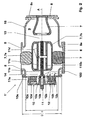
- FIG. 2 shows an earthing 1 'integrated in the mounting cover 10 according to the invention.
- This is shown by way of example with reference to a combined isolator / earthing switchgear 1 '.
- an earth drive 11 shown without outside existing motor drive unit
- a movable earth contact 110c and a fixed earth contact 12 are present.
- the movable earth contact 110c and the earth contact 12 are arranged in a gas space 9 of the gas-insulated switchgear 15.
- the grounding switching device 1 ' is mechanically connected in the region of the stationary earth contact 12 with the housing 2 of the gas-insulated switchgear 15.
- the mounting lid 10 of the gas-insulated switchgear 15 has a concave-shaped volume 100 widening the gas space 9 and the stationary earth contact 12 is mounted on an inner side 10e of the mounting lid 10 and at least partially arranged in the construction volume 100 of the mounting lid 10.
- the mounting lid 10 may be substantially cylindrical and have a substantially cylindrical volume 100 for receiving the stationary contact 12.
- a lid side wall 10c is formed substantially as a cylinder jacket 10c which extends along the axis A and away from the active parts 7 over the depth T and is closed at the end by a substantially circular lid bottom 10d.
- the inner side of the cover 10e then also provides a substantially circular or, as shown, annular, preferably planar, mounting surface for the fixed earth contact 12.
- the mounting lid 10 with the integrated earthing contact 12 is arranged on the end of the housing 2 of the gas-insulated switchgear 15.
- This will be a very compact design for the combined separator / earth electrode 1 'achieved and in particular a short length along the axis A.
- the separation section 13 and the grounding path 14 are arranged here by way of example in series one behind the other. Nevertheless, compact outer dimensions of the isolator / earthing switchgear 1 'are achieved.
- the mounting lid 10 should be designed larger than a standard flange of the gas-insulated switchgear 15.
- the mounting lid 10 has an opening diameter D, which is substantially equal to a diameter d (exemplified here as the inner diameter d) of the gas-insulated switchgear 15.
- the mounting flange 10 should be selected to be as large as the outer dimensions of the switchgear section 15 or of the switching device 1 'allow.
- the mounting lid 10 has a recess 10b for the passage of the Erderantriebs 11, in particular a drive shaft 11a and an insulating shaft 11b, for the movable earthing contact 110c.
- the earth drive 11 comprises a flying spindle 11b driven by the shaft 11a, 11b for the linear drive of the tubular movable earth contact 110c arranged in the gas space 9.
- the movable contact piece 110c can be arranged in the interior 9 of the switchgear 15 in the shield 7b and be moved from the inside to the outside so that the stationary contact 12 can be integrated on the housing cover 10 on the housing side.
- the earthing contact 12 between its contact system 12a and the mounting cover 10 on an electrical insulation 12b.
- the earthing contact 12 has an electrically insulated passage 12c through the housing 2 to the outside.
- a conductive strap (not shown here) can be mounted between the ground contact 12c and the housing 2 in a manner known per se.
- the grounding switching device 1 'with the fixed earth contact 12 integrated in the mounting cover 10 can, as shown, be part of a combined isolator / earthing contactor 1' and in particular have a common disconnector / earthing drive 11.
- the earth switch device 1 'with built-in cover 10 integrated contact terminal 12 can also in an angle separator, in another embodiment of the combined separator / Erder 1' or separately, d. H. without disconnector function, be realized.
- Other earth drives 11 are compatible with the invention and are hereby incorporated by reference.
- the earthing contact 12 can be completely pre-assembled in the mounting cover 10. He can then particularly easily together with the mounting cover 10 to the housing 2 of the switching device 1 'grown, in particular flanged over the flanges 10a, are. Overall, the assembly, the revision and the maintenance of the switchgear 15 is simplified by the integrated in the mounting cover 10 integrated circuit device 1, since the active parts 7 can be installed, removed and replaced by the mounting flange 10 without the housing 2 must be removed.
- the grounding device 1 ' is particularly suitable for gas-insulated medium or high voltage switchgear 15. Claimed is also a switchgear 15 with such a grounding device 1 '.
Landscapes
- Engineering & Computer Science (AREA)
- Power Engineering (AREA)
- Health & Medical Sciences (AREA)
- Public Health (AREA)
- Gas-Insulated Switchgears (AREA)
Description
- Die Erfindung bezieht sich auf das Gebiet der Hochspannungstechnik, insbesondere auf elektrische Isolations- und Anschlusstechnik für geerdete gasisolierte Schaltanlagen. Sie geht aus von einer dielektrischen Durchführung und einem elektrischen Hochspannungsapparate gemäss Oberbegriff der unabhängigen Patentansprüche.
- Erderschaltgeräte in bestehenden gasisolierten Schaltanlagen werden an speziellen Flanschen in den Schaltanlagen montiert. Diese Flansche sind entweder Standardflansche, welche bei jeder Verbindung benützt werden oder sogar kleinere Flansche, welche speziell für den Anbau von Erderschaltgeräten gemacht wurden. Die Flansche für den Erderanbau sind in der Regel zu klein, um bei der Montage durch diese hindurch die Aktivteile einzuführen oder zu befestigen. Zudem ist der Erderfestkontakt typischerweise in die Aktivteile im Innenrohr integriert. Bei den meisten heutigen Realisierungen von Erderschaltgeräten wird der bewegte Kontakt von aussen, d. h. von der Kapselung her, nach innen zu den Aktivteilen hin bewegt.
- Die Erfindung nimmt auf einen Stand der Technik Bezug, wie er aus dem Artikel von M. Okabe et al., "Serialization of Standard Gas Insulated Switchgear", Hitachi Review Vol. 51 (2002), No. 5 bekannt ist. Dort ist ein herkömmlicher kombinierter Trenner/Erder-Schalter oder Dreistellungstrenner offenbart, bei dem ein verschiebliches Kontaktteil durch Linearbewegung zwischen den Positionen "Trenner eingeschaltet", d. h. Trennerkontakt geschlossen, "Trenner ausgeschaltet", d. h. Trennerkontakt geöffnet und "Erder eingeschaltet", d. h. Erderkontakt zusätzlich geschlossen, bewegbar ist. Der Erderfestkontakt ist wie bisher üblich auf einem flachen Deckel der gasisolierten Schaltanlage (GIS) an der Deckelinnenseite montiert und ragt im angeflanschten Zustand vom Deckel in den gasisolierten Schalterraum hinein. Dadurch beansprucht der Erder relativ viel Bauraum in der gasisolierten Schaltanlage. Der Erderfestkontakt ist elektrisch vom GIS-Gehäuse isoliert und kann über einen Kontaktbügel mit dem GIS-Gehäuse kurzgeschlossen werden.
- Die EP 1 068 624 B1 offenbart ebenfalls einen kombinierten Trenner/Erder-Schalter. Hierbei ist der Erderfestkontakt als pinartiges Kontaktstück ausgebildet, das auf einem Kontaktträger aufsitzt, der seinerseits an einem durch die GIS-Gehäusewand nach aussen geführten Bolzen gehaltert ist.
- Die EP 1 128 509 A1 offenbart auch einen kombinierten Trenner/Erder-Schalter. Der Erderfestkontakt ist in einem konisch zulaufenden Teil des GIS-Gehäuses integriert, wobei dieser GIS-Gehäuseteil von einem aufgeschraubten Deckel mit geringem Durchmesser verschlossen ist. Diese Konstruktion ist insofern aufwendig, als das GIS-Gehäuse zur Aufnahme des Erders speziell ausgebildet ist und insbesondere zur Schaffung eines die Erderschaltstrecke aufnehmenden Bauvolumens erderseitig deutlich verlängert ausgestaltet ist.
- Die EP 1 361 633 A2 offenbart ebenso einen kombinierten Trenner/Erder-Schalter.
- Aufgabe der vorliegenden Erfindung ist es, für Erderschaltgeräte in gasisolierten Schaltanlagen eine verbesserte kompakte Bauweise anzugeben. Diese Aufgabe wird erfindungsgemäss durch die Merkmale der unabhängigen Ansprüche gelöst.
- Die Erfindung ist in Anspruch 1 definiert. Der Montagedeckel stellt also ein Bauvolumen zur Verfügung und begrenzt oder umschliesst dieses. Auf diese Weise wird ein Montageflansch mit integriertem Erderfestkontakt realisiert, wobei der Erdefestkontakt sehr platzsparend im Bauvolumen des Montagedeckels angeordnet ist. Der Erderfestkontakt ist derart montiert, dass er mindestens teilweise im Bauvolumen sitzt. Da der Erderfestkontakt über einen Montagedeckel oder Montageflansch am Gehäuse der gasisolierten Schaltanlage befestigt ist, kann er sehr leicht montiert oder demontiert werden.
- Gemäss der Erfindung ist der Erderfestkontakt vollständig im Bauvolumen des Montagedeckels oder Montageflansches angeordnet. Durch diese Anordnung des Erderfestkontakts am und im Montagedeckel kann der Platzbedarf des Erders markant verringert werden, sowohl im Vergleich zu bisherigen Anordnungen mit innenliegendem Erderantrieb als auch ganz besonders im Vergleich zu seitlich angebauten Erdern, deren Festkontakte in den Aktivteilen der gasisolierten Schaltanlage (GIS) angeordnet sind.
- Das Ausführungsbeispiel gemäss Anspruch 2 hat den Vorteil, dass der Montagedeckel eine einfache Form hat und zugleich ein grosses Bauvolumen halbseitig umschliesst.
- Das Ausführungsbeispiel gemäss Anspruch 3 hat den Vorteil, dass der Erderantrieb durch die bezüglich einer Längsachse des Schaltanlagenabschnitts endseitige Montage platzsparend in der gasisolierten Schaltanlage angeordnet ist.
- Die Ausführungsbeispiele gemäss Anspruch 4 und 5 haben den Vorteil, dass der Montageflansch einen grossflächigen Zugang zum Innenraum der GIS-Anlage bietet, so dass Aktivteile durch den Montageflansch sehr einfach eingeführt, montiert, gewartet oder ausgetauscht werden können, ohne dass das Gehäuse entfernt werden muss. Da der Montageflansch grösser als ein Standardflansch und insbesondere gleich gross wie das GIS-Gehäuse ist, können auch grössere Aktivteile verwendet werden.
- Anspruch 6 betrifft eine vorteilhafte Ausgestaltung des Erderantriebs, bei dem die Antriebswelle für den innenliegenden Vortrieb des beweglichen Erderkontakts vorzugsweise zentral durch den Montagedeckel geführt ist.
- Anspruch 7 betrifft eine Ausführung des Erders als isolierter Erder, der besonders für genaue elektrische Messungen an geerdeten Aktivteilen der Schaltanlage von Vorteil ist.
- Anspruch 8 gibt eine vorteilhafte Integration des kompakten Erders in einem kombinierten Trenner/Erder-Schaltgerät an.
- Anspruch 9 betrifft eine elektrische Schaltanlage umfassend ein Erdschaltgerät wie zuvor beschrieben und mit den dort genannten Vorteilen.
- Weitere Ausführungen, Vorteile und Anwendungen der Erfindung ergeben sich aus Anspruchskombinationen sowie aus der nun folgenden Beschreibung und den Figuren.
-
- Fig. 1
- zeigt schematisch im Querschnitt ein konventionelles Erderschaltgerät gemäss Stand der Technik, das seitlich an der gasisolierten Schaltanlage angebaut ist; und
- Fig. 2
- zeigt schematisch im Querschnitt ein Ausführungsbeispiel eines erfindungsgemäss im Montagedeckel integrierten, kompakten Erderschaltgeräts.
- In den Figuren sind gleiche Teile mit gleichen Bezugszeichen versehen.
- Fig. 1 zeigt ein herkömmliches Erderschaltgerät 1 in einer gekapselten gasisolierten Schaltanlage 15. Das Gehäuse 2 der gasisolierten Schaltanlage 15 umschliesst einen Gasraum 9, der bevorzugt mit SF6-Gas unter einigen bar Druck gefüllt ist. Im Gasraum 9 befinden sich spannungs- und stromtragende Aktivteile 7 der Schaltanlage 15, die von Isolatoren 8 und gegebenenfalls einer Montagehalterung 7a getragen sind. Statt Halterung 7a kann auch eine optionale Stromverbindung 7a vorhanden sein. Bei den Isolatoren 8 kann es sich beispielsweise um Stützisolatoren 8 oder gasdichte Schottisolatoren 9 handeln, die über Flansche 8a am Gehäuse 2 befestigt sind.
- Der Erderanbau 3 mit Erderantrieb 11 ist mitsamt seinem Erdergehäuse 3a über einen Flansch 4 seitlich an das GIS-Gehäuse 2 angeflanscht. Vom Antrieb 11 kann ein beweglicher Erderkontaktstift 5 in einen Erderfestkontakt 6 eingefahren werden, der in einem Aktivteil 7 der Schaltanlage 15 vorhanden ist. Im Normalbetrieb der Schaltanlage 15 ist der Stift 5 zurückgezogen und die Aktivteile 7 stehen unter Hochspannung und/oder tragen Betriebsstrom oder Kurzschlussstrom.
- Fig. 2 zeigt einen erfindungsgemäss im Montagedeckel 10 integrierten Erder 1'. Dieser ist beispielhaft anhand eines kombinierten Trenner/Erder-Schaltgeräts 1' gezeigt. Wiederum sind ein Erderantrieb 11 (dargestellt ohne ausserhalb vorhandene Motorantriebseinheit), ein beweglicher Erderkontakt 110c und ein Erderfestkontakt 12 vorhanden. Der bewegliche Erderkontakt 110c und der Erderfestkontakt 12 sind in einem Gasraum 9 der gasisolierten Schaltanlage 15 angeordnet. Das Erderschaltgerät 1' ist im Bereich des Erderfestkontakts 12 mit dem Gehäuse 2 der gasisolierten Schaltanlage 15 mechanisch verbunden. Erfindungsgemäss weist der Montagedeckel 10 der gasisolierten Schaltanlage 15 ein konkav geformtes, den Gasraum 9 erweiterndes Bauvolumen 100 auf und ist der Erderfestkontakt 12 an einer Innenseite 10e des Montagedeckels 10 montiert und mindestens teilweise im Bauvolumen 100 des Montagedeckels 10 angeordnet. Im folgenden werden bevorzugte Ausführungsbeispiele angegeben.
- Mit Vorteil weist der Erderfestkontakt 12, bezogen auf eine axiale Erstreckung senkrecht zum Montagedeckel 10, d. h. längs der Achse A des Schaltanlagenabschnitts 15, eine Baulänge L kleiner oder gleich einer Bautiefe T des Bauvolumens 100 auf. Wie dargestellt kann der Montagedeckel 10 im wesentlichen zylindrisch sein und ein im wesentlichen zylindrisches Bauvolumen 100 zur Aufnahme des Erderfestkontakts 12 aufweisen. In diesem Fall ist eine Deckelseitenwand 10c im wesentlichen als Zylindermantel 10c geformt, der sich entlang der Achse A und weg von den Aktivteilen 7 über die Bautiefe T erstreckt und endseitig durch einen im wesentlichen kreisrunden Deckelboden 10d abgeschlossen ist. Die Deckelinnenseite 10e stellt dann auch eine im wesentlichen kreisrunde oder wie dargestellt ringförmige, bevorzugt plane Montagefläche für den Erderfestkontakt 12 zur Verfügung.
- Bevorzugt ist der Montagedeckel 10 mit dem integrierten Erderfestkontakt 12 endseitig am Gehäuse 2 der gasisolierten Schaltanlage 15 angeordnet. Dadurch wird eine sehr kompakte Bauweise für den kombinierten Trenner/Erder 1' erreicht und insbesondere eine kurze Baulänge entlang der Achse A. Die Trennstrecke 13 und die Erdungsstrecke 14 sind hier beispielhaft in Serie hintereinander angeordnet. Trotzdem werden kompakte Aussenmasse des Trenner/Erder-Schaltgeräts 1' erreicht.
- Für einen grossflächigen Zugang zum Inneren des Trenner/Erder-Schaltgeräts 1' soll der Montagedeckel 10 grösser als ein Standardflansch der gasisolierten Schaltanlage 15 ausgelegt sein. Vorzugsweise weist der Montagedeckel 10 einen Öffnungsdurchmesser D auf, der im wesentlichen gleich einem Durchmesser d (hier beispielhaft dargestellt als Innendurchmesser d) der gasisolierten Schaltanlage 15 ist. Mit anderen Worten soll der Montageflansch 10 so gross gewählt sein, wie es die äusseren Abmessungen des Schaltanlagenabschnitts 15 oder des Schaltgeräts 1' zulassen. Dadurch können Aktivteile 7 der Schaltanlage 15 und auch Teile des Erder- oder Trenner/Erder-Schaltgeräts 1' einfach durch die Öffnung des Montagedeckels 10 eingebaut, ausgebaut oder gewartet werden.
- In der dargestellten Ausführungsform weist der Montagedeckel 10 eine Ausnehmung 10b zur Durchführung des Erderantriebs 11, insbesondere einer Antriebswelle 11a und einer Isolierwelle 11b, für den beweglichen Erderkontakt 110c auf. Insbesondere umfasst der Erderantrieb 11 eine fliegende, durch die Welle 11a, 11b angetriebene Spindel 11b zum Linearantrieb des im Gasraum 9 angeordneten, rohrförmigen beweglichen Erderkontakts 110c. In dieser beispielhaften Konfiguration kann das bewegliche Kontaktstück 110c im Inneren 9 der Schaltanlage 15 in der Abschirmung 7b angeordnet sein und von innen nach aussen bewegt werden, so dass der Erderfestkontakt 12 am gehäuseseitig vorhandenen Montagedeckel 10 integrierbar ist.
- Falls für den Erder 1' eine Ausführung mit isoliertem Erderfestkontakt 12 benötigt wird, sind auch die dafür notwendige elektrische Isolierung und die elektrischen Verbindungen im Montagedeckel 10 integriert. Hierfür weist der Erderfestkontakt 12 zwischen seinem Kontaktsystem 12a und dem Montagedeckel 10 eine elektrische Isolation 12b auf. Insbesondere weist der Erderfestkontakt 12 eine elektrisch isolierte Durchführung 12c durch das Gehäuse 2 nach aussen auf. Zum Kurzschliessen des Erders 1' mit dem Gehäuse 2 kann auf an sich bekannte Weise ein leitender Bügel (hier nicht dargestellt) zwischen dem durchgeführten Erdkontakt 12c und dem Gehäuse 2 montiert sein.
- Das Erderschaltgerät 1' mit erfindungsgemäss im Montagedeckel 10 integriertem Erderfestkontakt 12 kann, wie gezeigt, Bestandteil eines kombinierten Trenner/Erder-Schaltgeräts 1' sein und insbesondere einen gemeinsamen Trenner/Erder-Antrieb 11 aufweisen. Das Erderschaltgerät 1' mit im Montagedeckel 10 integriertem Erderfestkontakt 12 kann auch in einem Winkeltrenner, in einer anderen Ausführungsvariante des kombinierten Trenner/Erders 1' oder separat, d. h. ohne Trennerfunktion, realisiert sein. Auch andere Erderantriebe 11 sind mit der Erfindung kompatibel und gelten hiermit als mitoffenbart.
- Der Erderfestkontakt 12 kann vollständig im Montagedeckel 10 vormontiert sein. Er kann dann besonders einfach zusammen mit dem Montagedeckel 10 an das Gehäuse 2 des Schaltgeräts 1' angebaut, insbesondere über die Flansche 10a angeflanscht, werden. Insgesamt wird durch das im Montagedeckel 10 integrierte Schaltgerät 1' der Zusammenbau, die Revision und die Wartung der Schaltanlage 15 vereinfacht, da die Aktivteile 7 durch den Montageflansch 10 eingebaut, ausgebaut und ersetzt werden können, ohne dass das Gehäuse 2 entfernt werden muss.
- Das Erderschaltgerät 1' ist besonders für gasisolierte Mittel- oder Hochspannungsschaltanlagen 15 geeignet. Beansprucht wird auch eine Schaltanlage 15 mit einem solchen Erderschaltgerät 1'.
-
- 1
- Herkömmlicher Erder (seitlich angebaut)
- 1'
- Kombinierter Trenner/Erder in Kompaktbauweise
- 2
- GIS-Gehäuse
- 3
- Erderanbau mit Erderantrieb
- 3a
- Erdergehäuse
- 4
- Flansch für Erderanbau
- 5
- Beweglicher Erderkontaktstift
- 6
- Erderfestkontakt
- 7
- Aktivteile der Schaltanlage, Stromleiter (auf Hochspannungspotential)
- 7a
- Halterung, optionale Stromverbindung
- 7b
- Abschirmung für bewegliches Kontaktrohr
- 8
- Isolator, Stützisolator, Schottisolator
- 8a
- Isolatorflansch
- 9
- Gasraum, SF6
- 10
- Montagedeckel, Montageflansch mit integriertem Erderfestkontakt
- 10a
- Anflanschung für Montagedeckel
- 10b
- Ausnehmung für Trenner/Erder-Antrieb, Antriebsdurchführung
- 10c
- Deckelseitenwand, Zylindermantel
- 10d
- Deckelboden, Zylinderboden
- 10e
- Deckelinnenseite
- 100
- Montagedeckelvolumen
- 11
- Trenner/Erder-Antrieb
- 11a
- Antriebswelle
- 11b
- Isolierwelle
- 11c
- Spindel
- 11d
- Kontaktrohr, Schaltstange
- 110c
- beweglicher Erderkontakt
- 12
- Erderfestkontakt
- 12a
- Kontaktsystem
- 12b
- Isolation für isolierten Erder
- 12c
- Erder/Gehäuse-Durchführung
- 13
- Trennstrecke
- 14
- Erdungsstrecke
- 15
- gasisolierte Schaltanlage
- A
- Achse des Schaltanlagenabschnitts
- d
- Durchmesser des GIS-Gehäuses
- D
- Durchmesser des Montagedeckels
- L
- axiale Baulänge des Erderfestkontakts
- T
- axiale Bautiefe des Bauvolumens
Claims (9)
- Erderschaltgerät (1'), insbesondere für gasisolierte Hochspannungsschaltanlagen (15), umfassend einen Erderantrieb (11), einen beweglichen Erderkontakt (110c) und einen Erderfestkontakt (12), wobei der bewegliche Erderkontakt (110c) und der Erderfestkontakt (12) in einem Gasraum (9) der gasisolierten Schaltanlage (15) angeordnet sind, wobei ferner das Erderschaltgerät (1') im Bereich des Erderfestkontakts (12) mit dem Gehäuse (2) der gasisolierten Schaltanlage (15) mechanisch verbunden ist, dadurch gekennzeichnet, dassa) ein Montagedeckel (10) der gasisolierten Schaltanlage (15) ein konkav geformtes, den Gasraum (9) erweiterndes Bauvolumen (100) aufweist undb) der Erderfestkontakt (12) an einer Innenseite (10e) des Montagedeckels (10) montiert ist und im Bauvolumen (100) des Montagedeckels (10) angeordnet ist, wobei der Erderfestkontakt (12), bezogen auf eine axiale Erstreckung (A) senkrecht zum Montagedeckel (10), eine Baulänge (L) kleiner oder gleich einer Bautiefe (T) des Bauvolumens (100) aufweist.
- Das Erderschaltgerät (1') nach einem der vorangehenden Ansprüche, dadurch gekennzeichnet, dass der Montagedeckel (10) im wesentlichen zylindrisch ist und ein im wesentlichen zylindrisches Bauvolumen (100) zur Aufnahme des Erderfestkontakts (12) aufweist.
- Das Erderschaltgerät (1') nach einem der vorangehenden Ansprüche, dadurch gekennzeichnet, dass der Montagedeckel (10) mit dem integrierten Erderfestkontakt (12) endseitig am Gehäuse (2) der gasisolierten Schaltanlage (15) angeordnet ist.
- Das Erderschaltgerät (1') nach einem der vorangehenden Ansprüche, dadurch gekennzeichnet, dass der Montagedeckel (10) grösser als ein Standardflansch der gasisolierten Schaltanlage (15) ist.
- Das Erderschaltgerät (1') nach einem der vorangehenden Ansprüche, dadurch gekennzeichnet, dass der Montagedeckel (10) einen Öffnungsdurchmesser (D) aufweist, der im wesentlichen gleich einem Durchmesser (d) der gasisolierten Schaltanlage (15) ist.
- Das Erderschaltgerät (1') nach einem der vorangehenden Ansprüche, dadurch gekennzeichnet, dassa) der Montagedeckel (10) eine Ausnehmung (10b) zur Durchführung des Erderantriebs (11), insbesondere einer Antriebswelle (11a) und einer Isolierwelle (11b), für den beweglichen Erderkontakt (110c) aufweist undb) insbesondere dass der Erderantrieb (11) eine fliegende Spindel (11b) zum Linearantrieb des im Gasraum (9) angeordneten, rohrförmigen beweglichen Erderkontakts (110c) umfasst.
- Das Erderschaltgerät (1') nach einem der vorangehenden Ansprüche, dadurch gekennzeichnet, dassa) der Erderfestkontakt (12) zwischen seinem Kontaktsystem (12a) und dem Montagedeckel (10) eine elektrische Isolation (12b) aufweist undb) insbesondere dass der Erderfestkontakt (12) eine elektrisch isolierte Durchführung (12c) durch das Gehäuse (2) nach aussen aufweist.
- Das Erderschaltgerät (1') nach einem der vorangehenden Ansprüche, dadurch gekennzeichnet, dass das Erderschaltgerät (1') Bestandteil eines kombinierten Trenner/Erder-Schaltgeräts (1') ist und insbesondere einen gemeinsamen Trenner/Erder-Antrieb (11) aufweist.
- Elektrische Schaltanlage (15), insbesondere Hoch- oder Mittelspannungsschaltanlage (15), gekennzeichnet durch ein Erderschaltgerät (1') gemäss einem der vorangehenden Ansprüche.
Priority Applications (7)
| Application Number | Priority Date | Filing Date | Title |
|---|---|---|---|
| DE502004001795T DE502004001795D1 (de) | 2004-02-27 | 2004-02-27 | Kompaktes Erderschaltgerät für gasisolierte Schaltanlagen |
| AT04405116T ATE343217T1 (de) | 2004-02-27 | 2004-02-27 | Kompaktes erderschaltgerät für gasisolierte schaltanlagen |
| EP04405116A EP1569255B1 (de) | 2004-02-27 | 2004-02-27 | Kompaktes Erderschaltgerät für gasisolierte Schaltanlagen |
| KR1020050015418A KR101167615B1 (ko) | 2004-02-27 | 2005-02-24 | 기체 절연 개폐기 어셈블리용 콤팩트 접지 개폐기 |
| US11/066,184 US7122759B2 (en) | 2004-02-27 | 2005-02-25 | Compact earthing switch for gas-insulated switchgear assemblies |
| CN2005100516783A CN1661874B (zh) | 2004-02-27 | 2005-02-25 | 气体绝缘的开关设备组件用的紧凑型接地开关 |
| JP2005051012A JP4472555B2 (ja) | 2004-02-27 | 2005-02-25 | ガス絶縁式のスイッチギア装置のためのコンパクトなアース用スイッチ |
Applications Claiming Priority (1)
| Application Number | Priority Date | Filing Date | Title |
|---|---|---|---|
| EP04405116A EP1569255B1 (de) | 2004-02-27 | 2004-02-27 | Kompaktes Erderschaltgerät für gasisolierte Schaltanlagen |
Publications (2)
| Publication Number | Publication Date |
|---|---|
| EP1569255A1 EP1569255A1 (de) | 2005-08-31 |
| EP1569255B1 true EP1569255B1 (de) | 2006-10-18 |
Family
ID=34746197
Family Applications (1)
| Application Number | Title | Priority Date | Filing Date |
|---|---|---|---|
| EP04405116A Expired - Lifetime EP1569255B1 (de) | 2004-02-27 | 2004-02-27 | Kompaktes Erderschaltgerät für gasisolierte Schaltanlagen |
Country Status (7)
| Country | Link |
|---|---|
| US (1) | US7122759B2 (de) |
| EP (1) | EP1569255B1 (de) |
| JP (1) | JP4472555B2 (de) |
| KR (1) | KR101167615B1 (de) |
| CN (1) | CN1661874B (de) |
| AT (1) | ATE343217T1 (de) |
| DE (1) | DE502004001795D1 (de) |
Families Citing this family (17)
| Publication number | Priority date | Publication date | Assignee | Title |
|---|---|---|---|---|
| CN1830123B (zh) * | 2003-08-07 | 2012-02-08 | 阿雷瓦输配电公司 | 具有三个开关位置的接地开关 |
| EP1569254A1 (de) * | 2004-02-27 | 2005-08-31 | ABB Technology AG | Schaltgerät mit Trenn-und/oder Erdungsfunktion |
| DE102006033898A1 (de) * | 2006-07-18 | 2008-01-31 | Siemens Ag | Elektrisches Schaltgerät mit einem längs einer Bewegungsachse bewegbaren Kontaktstück |
| DE102006056656A1 (de) * | 2006-11-29 | 2008-06-12 | Areva Sachsenwerk Gmbh | Schaltermodul für eine elektrische Schaltanlage |
| KR100848124B1 (ko) | 2007-12-17 | 2008-07-24 | 홍정애 | 부하개폐기 |
| JP4906892B2 (ja) * | 2009-08-12 | 2012-03-28 | 株式会社日立製作所 | スイッチギヤ |
| DE102010004981B3 (de) * | 2010-01-18 | 2011-07-21 | Abb Technology Ag | Metallgekapselter, gasisolierter kombinierter Trenn- und Erdungsschalter |
| KR20120127851A (ko) * | 2011-05-16 | 2012-11-26 | 현대중공업 주식회사 | 가스절연 개폐장치 |
| PL2715758T3 (pl) * | 2011-05-27 | 2017-10-31 | Abb Schweiz Ag | Rozłącznik uziemiający |
| EP2597662A1 (de) | 2011-11-28 | 2013-05-29 | ABB Technology AG | Erdschalter für gasisolierte Mittel- oder Hochspannungsanlage |
| WO2013185815A1 (en) * | 2012-06-13 | 2013-12-19 | Abb Technology Ltd | Bypass switch assembly |
| JP6204778B2 (ja) * | 2013-10-01 | 2017-09-27 | 株式会社東芝 | 開閉器の操作機構 |
| DE102016202329A1 (de) * | 2016-02-16 | 2017-08-17 | Siemens Aktiengesellschaft | Überspannungsableiteranordnung |
| CN110137004A (zh) * | 2019-06-04 | 2019-08-16 | 国网四川省电力公司技能培训中心 | 一种用于输电网络的电气开关装置 |
| EP3754681B1 (de) * | 2019-06-21 | 2026-01-21 | ABB Schweiz AG | Trennschalter mit drei positionen |
| US12230466B2 (en) | 2023-03-03 | 2025-02-18 | Hyundai Electric & Energy Systems Co., Ltd. | Earthing switch |
| US12476055B2 (en) | 2023-03-17 | 2025-11-18 | Hyundai Electric & Energy Systems Co., Ltd. | Earthing switch |
Family Cites Families (12)
| Publication number | Priority date | Publication date | Assignee | Title |
|---|---|---|---|---|
| DE1615835A1 (de) * | 1967-04-06 | 1971-09-09 | Bbc Brown Boveri & Cie | Trennvorrichtung fuer vollisolierte elektrische Hochspannungs-Schaltanlagen |
| DE19519301A1 (de) * | 1995-05-26 | 1996-11-28 | Abb Management Ag | Trenner für eine metallgekapselte gasisolierte Hochspannungsschaltanlage |
| DE19632574A1 (de) * | 1996-08-13 | 1998-02-19 | Abb Patent Gmbh | Trenn-Erderschalter für eine metallgekapselte, gasisolierte Hochspannungsschaltanlage |
| US6144005A (en) * | 1997-07-23 | 2000-11-07 | Hitachi, Ltd. | Vacuum switch and a vacuum switchgear using the same |
| DE59900721D1 (de) | 1998-04-03 | 2002-02-28 | Siemens Ag | Kapselungsbaustein mit einem in eine strombahn integrierten drei-stellungs-schalter für eine gasisolierte schaltanlage |
| DE19825386C2 (de) * | 1998-05-28 | 2000-05-11 | Siemens Ag | Kapselungsbaustein mit einem kombinierten Trenn-Erdungs-Schalter für eine gasisolierte Schaltanlage |
| JP2000253520A (ja) | 1999-02-25 | 2000-09-14 | Toshiba Corp | ガス絶縁開閉装置 |
| JP2000350318A (ja) | 1999-05-31 | 2000-12-15 | Toshiba Corp | ガス絶縁接地開閉器 |
| FR2805406B1 (fr) | 2000-02-23 | 2002-08-23 | Alstom | Commutateur electrique a trois positions avec un element de commutation mobile axialement |
| JP2002051416A (ja) | 2000-08-03 | 2002-02-15 | Toshiba Corp | ガス絶縁開閉器 |
| WO2002060027A1 (fr) * | 2001-01-26 | 2002-08-01 | Hitachi, Ltd. | Appareillage de commutation isole par du gaz |
| AU763276B2 (en) * | 2001-02-07 | 2003-07-17 | Hitachi Limited | Gas insulated switchgear |
-
2004
- 2004-02-27 DE DE502004001795T patent/DE502004001795D1/de not_active Expired - Lifetime
- 2004-02-27 EP EP04405116A patent/EP1569255B1/de not_active Expired - Lifetime
- 2004-02-27 AT AT04405116T patent/ATE343217T1/de active
-
2005
- 2005-02-24 KR KR1020050015418A patent/KR101167615B1/ko not_active Expired - Fee Related
- 2005-02-25 JP JP2005051012A patent/JP4472555B2/ja not_active Expired - Fee Related
- 2005-02-25 US US11/066,184 patent/US7122759B2/en not_active Expired - Fee Related
- 2005-02-25 CN CN2005100516783A patent/CN1661874B/zh not_active Expired - Fee Related
Also Published As
| Publication number | Publication date |
|---|---|
| KR20060042156A (ko) | 2006-05-12 |
| US7122759B2 (en) | 2006-10-17 |
| CN1661874A (zh) | 2005-08-31 |
| ATE343217T1 (de) | 2006-11-15 |
| CN1661874B (zh) | 2011-10-05 |
| JP4472555B2 (ja) | 2010-06-02 |
| JP2005245200A (ja) | 2005-09-08 |
| DE502004001795D1 (de) | 2006-11-30 |
| EP1569255A1 (de) | 2005-08-31 |
| US20050189326A1 (en) | 2005-09-01 |
| KR101167615B1 (ko) | 2012-07-20 |
Similar Documents
| Publication | Publication Date | Title |
|---|---|---|
| EP1569255B1 (de) | Kompaktes Erderschaltgerät für gasisolierte Schaltanlagen | |
| EP0744803B1 (de) | Trenner für eine metallgekapselte gasisolierte Hochspannungschaltanlage | |
| EP1577904B1 (de) | Hochspannungsdurchführung mit Feldsteuermaterial | |
| EP0688071B2 (de) | Metallgekapselte gasisolierte Schaltanlage | |
| EP1569256B1 (de) | Isoliertes Erderschaltgerät für gasisolierte Schaltanlagen | |
| EP0176665A2 (de) | Vollfeststoffisolierter Vakuumschalter | |
| EP1569313B1 (de) | Hochspannungsgerät mit Partikelfalle | |
| WO2005074074A2 (de) | Druckgasisolierter trennschalterbaustein und durchführungsanordnung | |
| EP1249910A2 (de) | Hochspannungs-Leistungsschalter für eine druckgasisolierte Schaltanlage | |
| DE60104788T2 (de) | Gasisolierter Leistungsschalter mit integriertem elektronischem Stromwandler | |
| EP0678952A1 (de) | Trenner für eine metallgekapselte gasisolierte Hochspannungsschaltanlage | |
| EP1629580B1 (de) | Schalteranordnung | |
| DE10219299B3 (de) | Einpolig gekapselte und gasisolierte Schaltanlage | |
| EP1629581A2 (de) | Trennschalteranordnung | |
| DD241810A1 (de) | Schalterpol fuer leistungsschalter | |
| EP2036178B1 (de) | Leistungsschalter mit einem gehäuse | |
| DE19958782B4 (de) | Durchführungsstützer und -stromwandler für metallgekapselte, luftisolierte Mittelspannungs-Schaltanlagen | |
| DE102006040036A1 (de) | Anordnung mit einem elektrischen Schaltgerät | |
| DE3718108A1 (de) | Vakuumschalter | |
| DE102006001237A1 (de) | Gasisolierte, dreiphasige gekapselte Schaltanlage | |
| DE102004006061A1 (de) | Hochspannungs-Freiluft-Durchführungsanordnung | |
| DE10325684B4 (de) | Schalteranordnung | |
| EP1629579A2 (de) | Freiluftdurchführung mit integriertem trennschalter | |
| DE19649613A1 (de) | Leistungsschalter-Modul für eine gasisolierte Hochspannungsschaltanlage | |
| AT232117B (de) | Trennschalter mit einem um die Symmetrieachse zwischen den beiden Trennpol-Elektroden drehbaren Trennbolzen |
Legal Events
| Date | Code | Title | Description |
|---|---|---|---|
| PUAI | Public reference made under article 153(3) epc to a published international application that has entered the european phase |
Free format text: ORIGINAL CODE: 0009012 |
|
| AK | Designated contracting states |
Kind code of ref document: A1 Designated state(s): AT BE BG CH CY CZ DE DK EE ES FI FR GB GR HU IE IT LI LU MC NL PT RO SE SI SK TR |
|
| AX | Request for extension of the european patent |
Extension state: AL LT LV MK |
|
| 17P | Request for examination filed |
Effective date: 20060113 |
|
| GRAP | Despatch of communication of intention to grant a patent |
Free format text: ORIGINAL CODE: EPIDOSNIGR1 |
|
| AKX | Designation fees paid |
Designated state(s): AT BE BG CH CY CZ DE DK EE ES FI FR GB GR HU IE IT LI LU MC NL PT RO SE SI SK TR |
|
| GRAS | Grant fee paid |
Free format text: ORIGINAL CODE: EPIDOSNIGR3 |
|
| GRAA | (expected) grant |
Free format text: ORIGINAL CODE: 0009210 |
|
| RTI1 | Title (correction) |
Free format text: COMPACT EARTHING SWITCH FOR GAS INSULATED SUBSTATION |
|
| AK | Designated contracting states |
Kind code of ref document: B1 Designated state(s): AT BE BG CH CY CZ DE DK EE ES FI FR GB GR HU IE IT LI LU MC NL PT RO SE SI SK TR |
|
| PG25 | Lapsed in a contracting state [announced via postgrant information from national office to epo] |
Ref country code: IT Free format text: LAPSE BECAUSE OF FAILURE TO SUBMIT A TRANSLATION OF THE DESCRIPTION OR TO PAY THE FEE WITHIN THE PRESCRIBED TIME-LIMIT;WARNING: LAPSES OF ITALIAN PATENTS WITH EFFECTIVE DATE BEFORE 2007 MAY HAVE OCCURRED AT ANY TIME BEFORE 2007. THE CORRECT EFFECTIVE DATE MAY BE DIFFERENT FROM THE ONE RECORDED. Effective date: 20061018 Ref country code: CZ Free format text: LAPSE BECAUSE OF FAILURE TO SUBMIT A TRANSLATION OF THE DESCRIPTION OR TO PAY THE FEE WITHIN THE PRESCRIBED TIME-LIMIT Effective date: 20061018 Ref country code: NL Free format text: LAPSE BECAUSE OF FAILURE TO SUBMIT A TRANSLATION OF THE DESCRIPTION OR TO PAY THE FEE WITHIN THE PRESCRIBED TIME-LIMIT Effective date: 20061018 Ref country code: RO Free format text: LAPSE BECAUSE OF FAILURE TO SUBMIT A TRANSLATION OF THE DESCRIPTION OR TO PAY THE FEE WITHIN THE PRESCRIBED TIME-LIMIT Effective date: 20061018 Ref country code: FI Free format text: LAPSE BECAUSE OF FAILURE TO SUBMIT A TRANSLATION OF THE DESCRIPTION OR TO PAY THE FEE WITHIN THE PRESCRIBED TIME-LIMIT Effective date: 20061018 Ref country code: SI Free format text: LAPSE BECAUSE OF FAILURE TO SUBMIT A TRANSLATION OF THE DESCRIPTION OR TO PAY THE FEE WITHIN THE PRESCRIBED TIME-LIMIT Effective date: 20061018 Ref country code: SK Free format text: LAPSE BECAUSE OF FAILURE TO SUBMIT A TRANSLATION OF THE DESCRIPTION OR TO PAY THE FEE WITHIN THE PRESCRIBED TIME-LIMIT Effective date: 20061018 Ref country code: IE Free format text: LAPSE BECAUSE OF FAILURE TO SUBMIT A TRANSLATION OF THE DESCRIPTION OR TO PAY THE FEE WITHIN THE PRESCRIBED TIME-LIMIT Effective date: 20061018 |
|
| REG | Reference to a national code |
Ref country code: GB Ref legal event code: FG4D Free format text: NOT ENGLISH |
|
| REG | Reference to a national code |
Ref country code: IE Ref legal event code: FG4D Free format text: LANGUAGE OF EP DOCUMENT: GERMAN Ref country code: CH Ref legal event code: EP |
|
| REF | Corresponds to: |
Ref document number: 502004001795 Country of ref document: DE Date of ref document: 20061130 Kind code of ref document: P |
|
| PG25 | Lapsed in a contracting state [announced via postgrant information from national office to epo] |
Ref country code: DK Free format text: LAPSE BECAUSE OF FAILURE TO SUBMIT A TRANSLATION OF THE DESCRIPTION OR TO PAY THE FEE WITHIN THE PRESCRIBED TIME-LIMIT Effective date: 20070118 Ref country code: BG Free format text: LAPSE BECAUSE OF FAILURE TO SUBMIT A TRANSLATION OF THE DESCRIPTION OR TO PAY THE FEE WITHIN THE PRESCRIBED TIME-LIMIT Effective date: 20070118 Ref country code: SE Free format text: LAPSE BECAUSE OF FAILURE TO SUBMIT A TRANSLATION OF THE DESCRIPTION OR TO PAY THE FEE WITHIN THE PRESCRIBED TIME-LIMIT Effective date: 20070118 |
|
| PG25 | Lapsed in a contracting state [announced via postgrant information from national office to epo] |
Ref country code: ES Free format text: LAPSE BECAUSE OF FAILURE TO SUBMIT A TRANSLATION OF THE DESCRIPTION OR TO PAY THE FEE WITHIN THE PRESCRIBED TIME-LIMIT Effective date: 20070129 |
|
| PG25 | Lapsed in a contracting state [announced via postgrant information from national office to epo] |
Ref country code: MC Free format text: LAPSE BECAUSE OF NON-PAYMENT OF DUE FEES Effective date: 20070228 |
|
| PG25 | Lapsed in a contracting state [announced via postgrant information from national office to epo] |
Ref country code: PT Free format text: LAPSE BECAUSE OF FAILURE TO SUBMIT A TRANSLATION OF THE DESCRIPTION OR TO PAY THE FEE WITHIN THE PRESCRIBED TIME-LIMIT Effective date: 20070320 |
|
| NLV1 | Nl: lapsed or annulled due to failure to fulfill the requirements of art. 29p and 29m of the patents act | ||
| GBV | Gb: ep patent (uk) treated as always having been void in accordance with gb section 77(7)/1977 [no translation filed] |
Effective date: 20061018 |
|
| REG | Reference to a national code |
Ref country code: IE Ref legal event code: FD4D |
|
| ET | Fr: translation filed | ||
| PLBE | No opposition filed within time limit |
Free format text: ORIGINAL CODE: 0009261 |
|
| STAA | Information on the status of an ep patent application or granted ep patent |
Free format text: STATUS: NO OPPOSITION FILED WITHIN TIME LIMIT |
|
| 26N | No opposition filed |
Effective date: 20070719 |
|
| PG25 | Lapsed in a contracting state [announced via postgrant information from national office to epo] |
Ref country code: GB Free format text: LAPSE BECAUSE OF FAILURE TO SUBMIT A TRANSLATION OF THE DESCRIPTION OR TO PAY THE FEE WITHIN THE PRESCRIBED TIME-LIMIT Effective date: 20061018 |
|
| BERE | Be: lapsed |
Owner name: ABB TECHNOLOGY A.G. Effective date: 20070228 |
|
| PG25 | Lapsed in a contracting state [announced via postgrant information from national office to epo] |
Ref country code: BE Free format text: LAPSE BECAUSE OF NON-PAYMENT OF DUE FEES Effective date: 20070228 |
|
| PG25 | Lapsed in a contracting state [announced via postgrant information from national office to epo] |
Ref country code: GR Free format text: LAPSE BECAUSE OF FAILURE TO SUBMIT A TRANSLATION OF THE DESCRIPTION OR TO PAY THE FEE WITHIN THE PRESCRIBED TIME-LIMIT Effective date: 20070119 |
|
| PG25 | Lapsed in a contracting state [announced via postgrant information from national office to epo] |
Ref country code: EE Free format text: LAPSE BECAUSE OF FAILURE TO SUBMIT A TRANSLATION OF THE DESCRIPTION OR TO PAY THE FEE WITHIN THE PRESCRIBED TIME-LIMIT Effective date: 20061018 |
|
| PG25 | Lapsed in a contracting state [announced via postgrant information from national office to epo] |
Ref country code: LU Free format text: LAPSE BECAUSE OF NON-PAYMENT OF DUE FEES Effective date: 20070227 Ref country code: CY Free format text: LAPSE BECAUSE OF FAILURE TO SUBMIT A TRANSLATION OF THE DESCRIPTION OR TO PAY THE FEE WITHIN THE PRESCRIBED TIME-LIMIT Effective date: 20061018 |
|
| PG25 | Lapsed in a contracting state [announced via postgrant information from national office to epo] |
Ref country code: HU Free format text: LAPSE BECAUSE OF FAILURE TO SUBMIT A TRANSLATION OF THE DESCRIPTION OR TO PAY THE FEE WITHIN THE PRESCRIBED TIME-LIMIT Effective date: 20070419 Ref country code: TR Free format text: LAPSE BECAUSE OF FAILURE TO SUBMIT A TRANSLATION OF THE DESCRIPTION OR TO PAY THE FEE WITHIN THE PRESCRIBED TIME-LIMIT Effective date: 20061018 |
|
| PGFP | Annual fee paid to national office [announced via postgrant information from national office to epo] |
Ref country code: DE Payment date: 20130219 Year of fee payment: 10 Ref country code: FR Payment date: 20130301 Year of fee payment: 10 Ref country code: CH Payment date: 20130220 Year of fee payment: 10 |
|
| PGFP | Annual fee paid to national office [announced via postgrant information from national office to epo] |
Ref country code: AT Payment date: 20130213 Year of fee payment: 10 |
|
| REG | Reference to a national code |
Ref country code: DE Ref legal event code: R119 Ref document number: 502004001795 Country of ref document: DE |
|
| REG | Reference to a national code |
Ref country code: CH Ref legal event code: PL |
|
| REG | Reference to a national code |
Ref country code: AT Ref legal event code: MM01 Ref document number: 343217 Country of ref document: AT Kind code of ref document: T Effective date: 20140227 |
|
| PG25 | Lapsed in a contracting state [announced via postgrant information from national office to epo] |
Ref country code: CH Free format text: LAPSE BECAUSE OF NON-PAYMENT OF DUE FEES Effective date: 20140228 Ref country code: LI Free format text: LAPSE BECAUSE OF NON-PAYMENT OF DUE FEES Effective date: 20140228 |
|
| REG | Reference to a national code |
Ref country code: FR Ref legal event code: ST Effective date: 20141031 |
|
| REG | Reference to a national code |
Ref country code: DE Ref legal event code: R119 Ref document number: 502004001795 Country of ref document: DE Effective date: 20140902 |
|
| PG25 | Lapsed in a contracting state [announced via postgrant information from national office to epo] |
Ref country code: AT Free format text: LAPSE BECAUSE OF NON-PAYMENT OF DUE FEES Effective date: 20140227 |
|
| PG25 | Lapsed in a contracting state [announced via postgrant information from national office to epo] |
Ref country code: DE Free format text: LAPSE BECAUSE OF NON-PAYMENT OF DUE FEES Effective date: 20140902 Ref country code: FR Free format text: LAPSE BECAUSE OF NON-PAYMENT OF DUE FEES Effective date: 20140228 |