EP1569255B1 - Interrupteur de mise à la terre compact pour Disjoncteurs à isolation par gas - Google Patents
Interrupteur de mise à la terre compact pour Disjoncteurs à isolation par gas Download PDFInfo
- Publication number
- EP1569255B1 EP1569255B1 EP04405116A EP04405116A EP1569255B1 EP 1569255 B1 EP1569255 B1 EP 1569255B1 EP 04405116 A EP04405116 A EP 04405116A EP 04405116 A EP04405116 A EP 04405116A EP 1569255 B1 EP1569255 B1 EP 1569255B1
- Authority
- EP
- European Patent Office
- Prior art keywords
- earthing
- contact
- gas
- switching device
- mounting lid
- Prior art date
- Legal status (The legal status is an assumption and is not a legal conclusion. Google has not performed a legal analysis and makes no representation as to the accuracy of the status listed.)
- Expired - Lifetime
Links
Images

Classifications
-
- H—ELECTRICITY
- H01—ELECTRIC ELEMENTS
- H01H—ELECTRIC SWITCHES; RELAYS; SELECTORS; EMERGENCY PROTECTIVE DEVICES
- H01H31/00—Air-break switches for high tension without arc-extinguishing or arc-preventing means
- H01H31/003—Earthing switches
-
- A—HUMAN NECESSITIES
- A47—FURNITURE; DOMESTIC ARTICLES OR APPLIANCES; COFFEE MILLS; SPICE MILLS; SUCTION CLEANERS IN GENERAL
- A47K—SANITARY EQUIPMENT; ACCESSORIES THEREFOR, e.g. TOILET ACCESSORIES
- A47K13/00—Seats or covers for all kinds of closets
- A47K13/005—Auxiliary or portable seats
-
- A—HUMAN NECESSITIES
- A47—FURNITURE; DOMESTIC ARTICLES OR APPLIANCES; COFFEE MILLS; SPICE MILLS; SUCTION CLEANERS IN GENERAL
- A47K—SANITARY EQUIPMENT; ACCESSORIES THEREFOR, e.g. TOILET ACCESSORIES
- A47K13/00—Seats or covers for all kinds of closets
- A47K13/02—Seats or covers for all kinds of closets of plastic materials
-
- H—ELECTRICITY
- H02—GENERATION; CONVERSION OR DISTRIBUTION OF ELECTRIC POWER
- H02B—BOARDS, SUBSTATIONS OR SWITCHING ARRANGEMENTS FOR THE SUPPLY OR DISTRIBUTION OF ELECTRIC POWER
- H02B13/00—Arrangement of switchgear in which switches are enclosed in, or structurally associated with, a casing, e.g. cubicle
- H02B13/02—Arrangement of switchgear in which switches are enclosed in, or structurally associated with, a casing, e.g. cubicle with metal casing
- H02B13/035—Gas-insulated switchgear
- H02B13/075—Earthing arrangements
Definitions
- the invention relates to the field of high-voltage engineering, in particular to electrical insulation and connection technology for grounded gas-insulated switchgear. It is based on a dielectric bushing and a high-voltage electrical apparatus according to the preamble of the independent claims.
- Earth-switching devices in existing gas-insulated switchgear are mounted on special flanges in the switchgear. These flanges are either standard flanges, which are used with every connection, or even smaller flanges, which have been specially made for the installation of earth switchgear.
- the flanges for soil cultivation are usually too small to introduce or attach the active parts during assembly through them.
- the earthing contact is typically integrated into the active parts in the inner tube. In most present day earth switchgear implementations, the moving contact is externally, i. H. from the encapsulation, moved inwards towards the active parts.
- the invention relates to a prior art as disclosed in the article by M. Okabe et al., Serialization of Standard Gas Insulated Switchgear, Hitachi Review Vol. 51 (2002), no. 5 is known.
- a conventional combined disconnector / earthing switch or three-position disconnector is disclosed, in which a displaceable contact part by linear movement between the positions "disconnector on”, ie disconnector contact closed, “disconnector off”, ie disconnector contact opened and "earthing switched on", ie earthing contact additionally closed, is movable.
- the earthing contact is mounted as usual on a flat lid of the gas-insulated switchgear (GIS) on the inside of the lid and protrudes in the flanged state of the lid in the gas-insulated switch room inside.
- GIS gas-insulated switchgear
- the earthing contact is electrically isolated from the GIS housing and can be shorted to the GIS housing via a contact clip.
- EP 1 068 624 B1 also discloses a combined isolator / earthing switch.
- the earthing contact is formed as a pin-like contact piece, which rests on a contact carrier, which in turn is supported on a guided through the GIS housing wall outwardly bolt.
- EP 1 128 509 A1 also discloses a combined disconnector / earthing switch.
- the earthing contact is integrated in a tapered part of the GIS housing, this GIS housing part being closed by a small-diameter screwed-on cover.
- This construction is complicated insofar as the GIS housing for receiving the earthing is specially designed and in particular for the creation of a Erderschaltumble receiving volume of construction erder paragraph significantly extended designed.
- EP 1 361 633 A2 also discloses a combined disconnector / earthing switch.
- the object of the present invention is to specify an improved compact design for earth-switching devices in gas-insulated switchgear. This object is achieved according to the invention by the features of the independent claims.
- the invention is defined in claim 1.
- the mounting lid thus provides a volume of construction and limits or encloses this. In this way, a mounting flange with integrated earthing contact is realized, the Erdefest Quilt is arranged very compactly in the volume of the mounting lid.
- the earthing contact is mounted so that it sits at least partially in the volume of construction. Since the earthing contact is attached via a mounting lid or mounting flange to the housing of the gas-insulated switchgear, it can be very easily assembled or disassembled.
- the fixed earth contact is arranged completely in the construction volume of the mounting lid or mounting flange.
- the embodiment according to claim 2 has the advantage that the mounting lid has a simple shape and at the same time encloses a large volume of construction on one side.
- the embodiment according to claim 3 has the advantage that the earth drive is arranged by the relative to a longitudinal axis of the switchgear section end-side mounting space saving in the gas-insulated switchgear.
- the embodiments according to claim 4 and 5 have the advantage that the mounting flange provides a large-area access to the interior of the GIS system, so that active parts can be very easily inserted, mounted, maintained or replaced by the mounting flange, without the housing must be removed , Since the mounting flange is larger than a standard flange and in particular the same size as the GIS housing, larger active parts can be used.
- Claim 6 relates to an advantageous embodiment of the Erderantriebs, wherein the drive shaft for the internal propulsion of the movable earthing contact is preferably guided centrally through the mounting lid.
- Claim 7 relates to an embodiment of the earth electrode as an insulated earth electrode, which is particularly advantageous for accurate electrical measurements of earthed active parts of the switchgear.
- Claim 8 indicates an advantageous integration of the compact earthing in a combined isolator / earthing contactor.
- Claim 9 relates to an electrical switchgear comprising a ground switching device as described above and with the advantages mentioned there.
- Fig. 1 shows a conventional grounding device 1 in an encapsulated gas-insulated switchgear 15.
- the housing 2 of the gas-insulated switchgear 15 encloses a gas space 9, which is preferably filled with SF 6 gas under some bar pressure.
- a gas space 9 there are voltage and current-carrying active parts 7 of the switchgear 15, which are supported by insulators 8 and optionally a mounting bracket 7a.
- an optional power connection 7a may also be present.
- the insulators 8 may be, for example, support insulators 8 or gas-tight bulkhead insulators 9, which are fastened to the housing 2 via flanges 8a.
- the Erderanbau 3 with Erder drive 11 is flanged together with its grounding housing 3a via a flange 4 laterally to the GIS housing 2. From the drive 11, a movable earth contact pin 5 can be retracted into a fixed earth contact 6, which is present in an active part 7 of the switchgear 15. In normal operation of the switchgear 15, the pin 5 is withdrawn and the active parts 7 are under high voltage and / or carry operating current or short-circuit current.
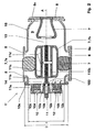
- FIG. 2 shows an earthing 1 'integrated in the mounting cover 10 according to the invention.
- This is shown by way of example with reference to a combined isolator / earthing switchgear 1 '.
- an earth drive 11 shown without outside existing motor drive unit
- a movable earth contact 110c and a fixed earth contact 12 are present.
- the movable earth contact 110c and the earth contact 12 are arranged in a gas space 9 of the gas-insulated switchgear 15.
- the grounding switching device 1 ' is mechanically connected in the region of the stationary earth contact 12 with the housing 2 of the gas-insulated switchgear 15.
- the mounting lid 10 of the gas-insulated switchgear 15 has a concave-shaped volume 100 widening the gas space 9 and the stationary earth contact 12 is mounted on an inner side 10e of the mounting lid 10 and at least partially arranged in the construction volume 100 of the mounting lid 10.
- the mounting lid 10 may be substantially cylindrical and have a substantially cylindrical volume 100 for receiving the stationary contact 12.
- a lid side wall 10c is formed substantially as a cylinder jacket 10c which extends along the axis A and away from the active parts 7 over the depth T and is closed at the end by a substantially circular lid bottom 10d.
- the inner side of the cover 10e then also provides a substantially circular or, as shown, annular, preferably planar, mounting surface for the fixed earth contact 12.
- the mounting lid 10 with the integrated earthing contact 12 is arranged on the end of the housing 2 of the gas-insulated switchgear 15.
- This will be a very compact design for the combined separator / earth electrode 1 'achieved and in particular a short length along the axis A.
- the separation section 13 and the grounding path 14 are arranged here by way of example in series one behind the other. Nevertheless, compact outer dimensions of the isolator / earthing switchgear 1 'are achieved.
- the mounting lid 10 should be designed larger than a standard flange of the gas-insulated switchgear 15.
- the mounting lid 10 has an opening diameter D, which is substantially equal to a diameter d (exemplified here as the inner diameter d) of the gas-insulated switchgear 15.
- the mounting flange 10 should be selected to be as large as the outer dimensions of the switchgear section 15 or of the switching device 1 'allow.
- the mounting lid 10 has a recess 10b for the passage of the Erderantriebs 11, in particular a drive shaft 11a and an insulating shaft 11b, for the movable earthing contact 110c.
- the earth drive 11 comprises a flying spindle 11b driven by the shaft 11a, 11b for the linear drive of the tubular movable earth contact 110c arranged in the gas space 9.
- the movable contact piece 110c can be arranged in the interior 9 of the switchgear 15 in the shield 7b and be moved from the inside to the outside so that the stationary contact 12 can be integrated on the housing cover 10 on the housing side.
- the earthing contact 12 between its contact system 12a and the mounting cover 10 on an electrical insulation 12b.
- the earthing contact 12 has an electrically insulated passage 12c through the housing 2 to the outside.
- a conductive strap (not shown here) can be mounted between the ground contact 12c and the housing 2 in a manner known per se.
- the grounding switching device 1 'with the fixed earth contact 12 integrated in the mounting cover 10 can, as shown, be part of a combined isolator / earthing contactor 1' and in particular have a common disconnector / earthing drive 11.
- the earth switch device 1 'with built-in cover 10 integrated contact terminal 12 can also in an angle separator, in another embodiment of the combined separator / Erder 1' or separately, d. H. without disconnector function, be realized.
- Other earth drives 11 are compatible with the invention and are hereby incorporated by reference.
- the earthing contact 12 can be completely pre-assembled in the mounting cover 10. He can then particularly easily together with the mounting cover 10 to the housing 2 of the switching device 1 'grown, in particular flanged over the flanges 10a, are. Overall, the assembly, the revision and the maintenance of the switchgear 15 is simplified by the integrated in the mounting cover 10 integrated circuit device 1, since the active parts 7 can be installed, removed and replaced by the mounting flange 10 without the housing 2 must be removed.
- the grounding device 1 ' is particularly suitable for gas-insulated medium or high voltage switchgear 15. Claimed is also a switchgear 15 with such a grounding device 1 '.
Landscapes
- Health & Medical Sciences (AREA)
- Public Health (AREA)
- Engineering & Computer Science (AREA)
- Power Engineering (AREA)
- Gas-Insulated Switchgears (AREA)
Claims (9)
- Interrupteur de mise à la terre (1'), notamment pour des équipements de commutation haute tension à isolement gazeux (15), comprenant un mécanisme d'entraînement de mise à la terre (11), un contact mobile de mise à la terre (110c) et un contact fixe de mise à la terre (12), le contact mobile de mise à la terre (110c) et le contact fixe de mise à la terre (12) étant disposés dans un espace de gaz (9) de l'équipement de commutation à isolement gazeux (15), l'interrupteur de mise à la terre (1') étant en outre relié mécaniquement avec le boîtier (2) de l'équipement de commutation à isolement gazeux (15) dans la zone du contact fixe de mise à la terre (12), caractérisé en ce quea) un couvercle de montage (10) de l'équipement de commutation à isolement gazeux (15) présente un volume hors tout (100) de forme concave qui étend l'espace de gaz (9) etb) le contact fixe de mise à la terre (12) est monté sur un côté intérieur (10e) du couvercle de montage (10) et il est disposé dans le volume hors tout (100) du couvercle de montage (10), le contact fixe de mise à la terre (12) présentant, perpendiculairement au couvercle de montage (10) par rapport à une extension axiale (A), une longueur hors tout (L) inférieure ou égale à une profondeur hors tout (T) du volume hors tout (100).
- Interrupteur de mise à la terre (1') selon la revendication 1, caractérisé en ce que le couvercle de montage (10) est essentiellement cylindrique et présente un volume hors tout (100) essentiellement cylindrique pour accueillir le contact fixe de mise à la terre (12).
- Interrupteur de mise à la terre (1') selon l'une des revendications précédentes, caractérisé en ce que le couvercle de montage (10) muni du contact fixe de mise à la terre (12) est disposé d'un côté sur le boîtier (2) de l'équipement de commutation à isolement gazeux (15).
- Interrupteur de mise à la terre (1') selon l'une des revendications précédentes, caractérisé en ce que le couvercle de montage (10) est plus grand qu'une bride standard de l'équipement de commutation à isolement gazeux (15).
- Interrupteur de mise à la terre (1') selon l'une des revendications précédentes, caractérisé en ce que le couvercle de montage (10) présente un diamètre d'ouverture (D) qui est pour l'essentiel égal à un diamètre (d) de l'équipement de commutation à isolement gazeux (15).
- Interrupteur de mise à la terre (1') selon l'une des revendications précédentes, caractérisé en ce quea) le couvercle de montage (10) présente un creux (10b) pour faire passer le mécanisme d'entraînement de mise à la terre (11), notamment un arbre d'entraînement (11a) et un arbre d'isolation (11b), pour le contact de mise à la terre mobile (110c) etb) notamment que le mécanisme d'entraînement de mise à la terre (11) comprend une broche mobile (11b) pour l'entraînement linéaire du contact de mise à la terre mobile (110c) de forme tubulaire disposé dans l'espace de gaz (9).
- Interrupteur de mise à la terre (1') selon l'une des revendications précédentes, caractérisé en ce quea) le contact fixe de mise à la terre (12) présente entre son système de contact (12a) et le couvercle de montage (10) une isolation électrique (12b) etb) notamment que le contact fixe de mise à la terre (12) présente une traversée électriquement isolée (12c) à travers le boîtier (2) vers l'extérieur.
- Interrupteur de mise à la terre (1') selon l'une des revendications précédentes, caractérisé en ce que l'interrupteur de mise à la terre (1') fait partie d'un commutateur combiné sectionneur/de mise à la terre (1') et présente notamment un mécanisme d'entraînement commun du sectionneur/élément de mise à la terre (1').
- Équipement de commutation électrique (15), notamment équipement de commutation à haute ou à moyenne tension (15), caractérisé par un interrupteur de mise à la terre (1') selon l'une des revendications précédentes.
Priority Applications (7)
| Application Number | Priority Date | Filing Date | Title |
|---|---|---|---|
| DE502004001795T DE502004001795D1 (de) | 2004-02-27 | 2004-02-27 | Kompaktes Erderschaltgerät für gasisolierte Schaltanlagen |
| AT04405116T ATE343217T1 (de) | 2004-02-27 | 2004-02-27 | Kompaktes erderschaltgerät für gasisolierte schaltanlagen |
| EP04405116A EP1569255B1 (fr) | 2004-02-27 | 2004-02-27 | Interrupteur de mise à la terre compact pour Disjoncteurs à isolation par gas |
| KR1020050015418A KR101167615B1 (ko) | 2004-02-27 | 2005-02-24 | 기체 절연 개폐기 어셈블리용 콤팩트 접지 개폐기 |
| CN2005100516783A CN1661874B (zh) | 2004-02-27 | 2005-02-25 | 气体绝缘的开关设备组件用的紧凑型接地开关 |
| US11/066,184 US7122759B2 (en) | 2004-02-27 | 2005-02-25 | Compact earthing switch for gas-insulated switchgear assemblies |
| JP2005051012A JP4472555B2 (ja) | 2004-02-27 | 2005-02-25 | ガス絶縁式のスイッチギア装置のためのコンパクトなアース用スイッチ |
Applications Claiming Priority (1)
| Application Number | Priority Date | Filing Date | Title |
|---|---|---|---|
| EP04405116A EP1569255B1 (fr) | 2004-02-27 | 2004-02-27 | Interrupteur de mise à la terre compact pour Disjoncteurs à isolation par gas |
Publications (2)
| Publication Number | Publication Date |
|---|---|
| EP1569255A1 EP1569255A1 (fr) | 2005-08-31 |
| EP1569255B1 true EP1569255B1 (fr) | 2006-10-18 |
Family
ID=34746197
Family Applications (1)
| Application Number | Title | Priority Date | Filing Date |
|---|---|---|---|
| EP04405116A Expired - Lifetime EP1569255B1 (fr) | 2004-02-27 | 2004-02-27 | Interrupteur de mise à la terre compact pour Disjoncteurs à isolation par gas |
Country Status (7)
| Country | Link |
|---|---|
| US (1) | US7122759B2 (fr) |
| EP (1) | EP1569255B1 (fr) |
| JP (1) | JP4472555B2 (fr) |
| KR (1) | KR101167615B1 (fr) |
| CN (1) | CN1661874B (fr) |
| AT (1) | ATE343217T1 (fr) |
| DE (1) | DE502004001795D1 (fr) |
Families Citing this family (17)
| Publication number | Priority date | Publication date | Assignee | Title |
|---|---|---|---|---|
| US7429710B2 (en) * | 2003-08-07 | 2008-09-30 | Areva T&D Sa | Three-position ground switch |
| EP1569254A1 (fr) * | 2004-02-27 | 2005-08-31 | ABB Technology AG | Interrupteur de mise à la terre et/ou sectionneur |
| DE102006033898A1 (de) * | 2006-07-18 | 2008-01-31 | Siemens Ag | Elektrisches Schaltgerät mit einem längs einer Bewegungsachse bewegbaren Kontaktstück |
| DE102006056656A1 (de) * | 2006-11-29 | 2008-06-12 | Areva Sachsenwerk Gmbh | Schaltermodul für eine elektrische Schaltanlage |
| KR100848124B1 (ko) | 2007-12-17 | 2008-07-24 | 홍정애 | 부하개폐기 |
| JP4906892B2 (ja) * | 2009-08-12 | 2012-03-28 | 株式会社日立製作所 | スイッチギヤ |
| DE102010004981B3 (de) * | 2010-01-18 | 2011-07-21 | Abb Technology Ag | Metallgekapselter, gasisolierter kombinierter Trenn- und Erdungsschalter |
| KR20120127851A (ko) * | 2011-05-16 | 2012-11-26 | 현대중공업 주식회사 | 가스절연 개폐장치 |
| US9190230B2 (en) * | 2011-05-27 | 2015-11-17 | Abb Technology Ag | Grounding switch |
| EP2597662A1 (fr) | 2011-11-28 | 2013-05-29 | ABB Technology AG | Prise de terre pour installation moyenne ou haute tension isolée du gaz |
| WO2013185815A1 (fr) * | 2012-06-13 | 2013-12-19 | Abb Technology Ltd | Ensemble commutateur de dérivation |
| JP6204778B2 (ja) * | 2013-10-01 | 2017-09-27 | 株式会社東芝 | 開閉器の操作機構 |
| DE102016202329A1 (de) * | 2016-02-16 | 2017-08-17 | Siemens Aktiengesellschaft | Überspannungsableiteranordnung |
| CN110137004A (zh) * | 2019-06-04 | 2019-08-16 | 国网四川省电力公司技能培训中心 | 一种用于输电网络的电气开关装置 |
| EP3754681B1 (fr) * | 2019-06-21 | 2026-01-21 | ABB Schweiz AG | Commutateur de déconnexion à trois positions |
| US12230466B2 (en) | 2023-03-03 | 2025-02-18 | Hyundai Electric & Energy Systems Co., Ltd. | Earthing switch |
| US12476055B2 (en) | 2023-03-17 | 2025-11-18 | Hyundai Electric & Energy Systems Co., Ltd. | Earthing switch |
Family Cites Families (12)
| Publication number | Priority date | Publication date | Assignee | Title |
|---|---|---|---|---|
| DE1615835A1 (de) * | 1967-04-06 | 1971-09-09 | Bbc Brown Boveri & Cie | Trennvorrichtung fuer vollisolierte elektrische Hochspannungs-Schaltanlagen |
| DE19519301A1 (de) * | 1995-05-26 | 1996-11-28 | Abb Management Ag | Trenner für eine metallgekapselte gasisolierte Hochspannungsschaltanlage |
| DE19632574A1 (de) * | 1996-08-13 | 1998-02-19 | Abb Patent Gmbh | Trenn-Erderschalter für eine metallgekapselte, gasisolierte Hochspannungsschaltanlage |
| US6144005A (en) * | 1997-07-23 | 2000-11-07 | Hitachi, Ltd. | Vacuum switch and a vacuum switchgear using the same |
| DE59900721D1 (de) | 1998-04-03 | 2002-02-28 | Siemens Ag | Kapselungsbaustein mit einem in eine strombahn integrierten drei-stellungs-schalter für eine gasisolierte schaltanlage |
| DE19825386C2 (de) * | 1998-05-28 | 2000-05-11 | Siemens Ag | Kapselungsbaustein mit einem kombinierten Trenn-Erdungs-Schalter für eine gasisolierte Schaltanlage |
| JP2000253520A (ja) | 1999-02-25 | 2000-09-14 | Toshiba Corp | ガス絶縁開閉装置 |
| JP2000350318A (ja) | 1999-05-31 | 2000-12-15 | Toshiba Corp | ガス絶縁接地開閉器 |
| FR2805406B1 (fr) | 2000-02-23 | 2002-08-23 | Alstom | Commutateur electrique a trois positions avec un element de commutation mobile axialement |
| JP2002051416A (ja) | 2000-08-03 | 2002-02-15 | Toshiba Corp | ガス絶縁開閉器 |
| WO2002060027A1 (fr) * | 2001-01-26 | 2002-08-01 | Hitachi, Ltd. | Appareillage de commutation isole par du gaz |
| AU763276B2 (en) * | 2001-02-07 | 2003-07-17 | Hitachi Limited | Gas insulated switchgear |
-
2004
- 2004-02-27 AT AT04405116T patent/ATE343217T1/de active
- 2004-02-27 DE DE502004001795T patent/DE502004001795D1/de not_active Expired - Lifetime
- 2004-02-27 EP EP04405116A patent/EP1569255B1/fr not_active Expired - Lifetime
-
2005
- 2005-02-24 KR KR1020050015418A patent/KR101167615B1/ko not_active Expired - Fee Related
- 2005-02-25 JP JP2005051012A patent/JP4472555B2/ja not_active Expired - Fee Related
- 2005-02-25 US US11/066,184 patent/US7122759B2/en not_active Expired - Fee Related
- 2005-02-25 CN CN2005100516783A patent/CN1661874B/zh not_active Expired - Fee Related
Also Published As
| Publication number | Publication date |
|---|---|
| US20050189326A1 (en) | 2005-09-01 |
| ATE343217T1 (de) | 2006-11-15 |
| CN1661874A (zh) | 2005-08-31 |
| JP2005245200A (ja) | 2005-09-08 |
| DE502004001795D1 (de) | 2006-11-30 |
| EP1569255A1 (fr) | 2005-08-31 |
| KR101167615B1 (ko) | 2012-07-20 |
| JP4472555B2 (ja) | 2010-06-02 |
| KR20060042156A (ko) | 2006-05-12 |
| CN1661874B (zh) | 2011-10-05 |
| US7122759B2 (en) | 2006-10-17 |
Similar Documents
| Publication | Publication Date | Title |
|---|---|---|
| EP1569255B1 (fr) | Interrupteur de mise à la terre compact pour Disjoncteurs à isolation par gas | |
| EP0744803B1 (fr) | Sectionneur pour une installation de commutation à haute tension, blindé et à isolation gazeuse | |
| EP1577904B1 (fr) | Traversée haute tension avec élément pour les contrôle du champ électrique | |
| EP0688071B2 (fr) | Appareillage de commutation blindé métallique à gaz isolant | |
| EP1569256B1 (fr) | Interrupteur de mise à la terre isolé pour sectionneurs isolés au gaz | |
| EP0176665A2 (fr) | Interrupteur à vide isolé entièrement par une substance solide | |
| WO2005074074A2 (fr) | Module de disjoncteur isole a l'aide de gaz sous pression et dispositif a traversee correspondant | |
| EP1249910A2 (fr) | Disjoncteur haute-tension pour une installation de commutation à isolation gaseuse | |
| DE60104788T2 (de) | Gasisolierter Leistungsschalter mit integriertem elektronischem Stromwandler | |
| EP0678952A1 (fr) | Sectionneur pour un appareillage de commutation blindé métallique à haute tension et à isolement gazeux | |
| EP1629580B1 (fr) | Ensemble commutateur | |
| DE10219299B3 (de) | Einpolig gekapselte und gasisolierte Schaltanlage | |
| WO2004109878A2 (fr) | Systeme de disjoncteurs | |
| DE69015922T2 (de) | Generatorlasttrennschalter. | |
| EP0222073A2 (fr) | Pôle d'interrupteur pour disjoncteur de puissance | |
| EP2036178B1 (fr) | Disjoncteur de puissance muni d'un boîtier | |
| DE19958782B4 (de) | Durchführungsstützer und -stromwandler für metallgekapselte, luftisolierte Mittelspannungs-Schaltanlagen | |
| DE102006040036A1 (de) | Anordnung mit einem elektrischen Schaltgerät | |
| DE3718108A1 (de) | Vakuumschalter | |
| DE102006001237A1 (de) | Gasisolierte, dreiphasige gekapselte Schaltanlage | |
| DE102004006061A1 (de) | Hochspannungs-Freiluft-Durchführungsanordnung | |
| DE10325684B4 (de) | Schalteranordnung | |
| EP1629579A2 (fr) | Traversee exterieure avec des sectionneurs integres | |
| DE19649613A1 (de) | Leistungsschalter-Modul für eine gasisolierte Hochspannungsschaltanlage | |
| AT232117B (de) | Trennschalter mit einem um die Symmetrieachse zwischen den beiden Trennpol-Elektroden drehbaren Trennbolzen |
Legal Events
| Date | Code | Title | Description |
|---|---|---|---|
| PUAI | Public reference made under article 153(3) epc to a published international application that has entered the european phase |
Free format text: ORIGINAL CODE: 0009012 |
|
| AK | Designated contracting states |
Kind code of ref document: A1 Designated state(s): AT BE BG CH CY CZ DE DK EE ES FI FR GB GR HU IE IT LI LU MC NL PT RO SE SI SK TR |
|
| AX | Request for extension of the european patent |
Extension state: AL LT LV MK |
|
| 17P | Request for examination filed |
Effective date: 20060113 |
|
| GRAP | Despatch of communication of intention to grant a patent |
Free format text: ORIGINAL CODE: EPIDOSNIGR1 |
|
| AKX | Designation fees paid |
Designated state(s): AT BE BG CH CY CZ DE DK EE ES FI FR GB GR HU IE IT LI LU MC NL PT RO SE SI SK TR |
|
| GRAS | Grant fee paid |
Free format text: ORIGINAL CODE: EPIDOSNIGR3 |
|
| GRAA | (expected) grant |
Free format text: ORIGINAL CODE: 0009210 |
|
| RTI1 | Title (correction) |
Free format text: COMPACT EARTHING SWITCH FOR GAS INSULATED SUBSTATION |
|
| AK | Designated contracting states |
Kind code of ref document: B1 Designated state(s): AT BE BG CH CY CZ DE DK EE ES FI FR GB GR HU IE IT LI LU MC NL PT RO SE SI SK TR |
|
| PG25 | Lapsed in a contracting state [announced via postgrant information from national office to epo] |
Ref country code: IT Free format text: LAPSE BECAUSE OF FAILURE TO SUBMIT A TRANSLATION OF THE DESCRIPTION OR TO PAY THE FEE WITHIN THE PRESCRIBED TIME-LIMIT;WARNING: LAPSES OF ITALIAN PATENTS WITH EFFECTIVE DATE BEFORE 2007 MAY HAVE OCCURRED AT ANY TIME BEFORE 2007. THE CORRECT EFFECTIVE DATE MAY BE DIFFERENT FROM THE ONE RECORDED. Effective date: 20061018 Ref country code: CZ Free format text: LAPSE BECAUSE OF FAILURE TO SUBMIT A TRANSLATION OF THE DESCRIPTION OR TO PAY THE FEE WITHIN THE PRESCRIBED TIME-LIMIT Effective date: 20061018 Ref country code: NL Free format text: LAPSE BECAUSE OF FAILURE TO SUBMIT A TRANSLATION OF THE DESCRIPTION OR TO PAY THE FEE WITHIN THE PRESCRIBED TIME-LIMIT Effective date: 20061018 Ref country code: RO Free format text: LAPSE BECAUSE OF FAILURE TO SUBMIT A TRANSLATION OF THE DESCRIPTION OR TO PAY THE FEE WITHIN THE PRESCRIBED TIME-LIMIT Effective date: 20061018 Ref country code: FI Free format text: LAPSE BECAUSE OF FAILURE TO SUBMIT A TRANSLATION OF THE DESCRIPTION OR TO PAY THE FEE WITHIN THE PRESCRIBED TIME-LIMIT Effective date: 20061018 Ref country code: SI Free format text: LAPSE BECAUSE OF FAILURE TO SUBMIT A TRANSLATION OF THE DESCRIPTION OR TO PAY THE FEE WITHIN THE PRESCRIBED TIME-LIMIT Effective date: 20061018 Ref country code: SK Free format text: LAPSE BECAUSE OF FAILURE TO SUBMIT A TRANSLATION OF THE DESCRIPTION OR TO PAY THE FEE WITHIN THE PRESCRIBED TIME-LIMIT Effective date: 20061018 Ref country code: IE Free format text: LAPSE BECAUSE OF FAILURE TO SUBMIT A TRANSLATION OF THE DESCRIPTION OR TO PAY THE FEE WITHIN THE PRESCRIBED TIME-LIMIT Effective date: 20061018 |
|
| REG | Reference to a national code |
Ref country code: GB Ref legal event code: FG4D Free format text: NOT ENGLISH |
|
| REG | Reference to a national code |
Ref country code: IE Ref legal event code: FG4D Free format text: LANGUAGE OF EP DOCUMENT: GERMAN Ref country code: CH Ref legal event code: EP |
|
| REF | Corresponds to: |
Ref document number: 502004001795 Country of ref document: DE Date of ref document: 20061130 Kind code of ref document: P |
|
| PG25 | Lapsed in a contracting state [announced via postgrant information from national office to epo] |
Ref country code: DK Free format text: LAPSE BECAUSE OF FAILURE TO SUBMIT A TRANSLATION OF THE DESCRIPTION OR TO PAY THE FEE WITHIN THE PRESCRIBED TIME-LIMIT Effective date: 20070118 Ref country code: BG Free format text: LAPSE BECAUSE OF FAILURE TO SUBMIT A TRANSLATION OF THE DESCRIPTION OR TO PAY THE FEE WITHIN THE PRESCRIBED TIME-LIMIT Effective date: 20070118 Ref country code: SE Free format text: LAPSE BECAUSE OF FAILURE TO SUBMIT A TRANSLATION OF THE DESCRIPTION OR TO PAY THE FEE WITHIN THE PRESCRIBED TIME-LIMIT Effective date: 20070118 |
|
| PG25 | Lapsed in a contracting state [announced via postgrant information from national office to epo] |
Ref country code: ES Free format text: LAPSE BECAUSE OF FAILURE TO SUBMIT A TRANSLATION OF THE DESCRIPTION OR TO PAY THE FEE WITHIN THE PRESCRIBED TIME-LIMIT Effective date: 20070129 |
|
| PG25 | Lapsed in a contracting state [announced via postgrant information from national office to epo] |
Ref country code: MC Free format text: LAPSE BECAUSE OF NON-PAYMENT OF DUE FEES Effective date: 20070228 |
|
| PG25 | Lapsed in a contracting state [announced via postgrant information from national office to epo] |
Ref country code: PT Free format text: LAPSE BECAUSE OF FAILURE TO SUBMIT A TRANSLATION OF THE DESCRIPTION OR TO PAY THE FEE WITHIN THE PRESCRIBED TIME-LIMIT Effective date: 20070320 |
|
| NLV1 | Nl: lapsed or annulled due to failure to fulfill the requirements of art. 29p and 29m of the patents act | ||
| GBV | Gb: ep patent (uk) treated as always having been void in accordance with gb section 77(7)/1977 [no translation filed] |
Effective date: 20061018 |
|
| REG | Reference to a national code |
Ref country code: IE Ref legal event code: FD4D |
|
| ET | Fr: translation filed | ||
| PLBE | No opposition filed within time limit |
Free format text: ORIGINAL CODE: 0009261 |
|
| STAA | Information on the status of an ep patent application or granted ep patent |
Free format text: STATUS: NO OPPOSITION FILED WITHIN TIME LIMIT |
|
| 26N | No opposition filed |
Effective date: 20070719 |
|
| PG25 | Lapsed in a contracting state [announced via postgrant information from national office to epo] |
Ref country code: GB Free format text: LAPSE BECAUSE OF FAILURE TO SUBMIT A TRANSLATION OF THE DESCRIPTION OR TO PAY THE FEE WITHIN THE PRESCRIBED TIME-LIMIT Effective date: 20061018 |
|
| BERE | Be: lapsed |
Owner name: ABB TECHNOLOGY A.G. Effective date: 20070228 |
|
| PG25 | Lapsed in a contracting state [announced via postgrant information from national office to epo] |
Ref country code: BE Free format text: LAPSE BECAUSE OF NON-PAYMENT OF DUE FEES Effective date: 20070228 |
|
| PG25 | Lapsed in a contracting state [announced via postgrant information from national office to epo] |
Ref country code: GR Free format text: LAPSE BECAUSE OF FAILURE TO SUBMIT A TRANSLATION OF THE DESCRIPTION OR TO PAY THE FEE WITHIN THE PRESCRIBED TIME-LIMIT Effective date: 20070119 |
|
| PG25 | Lapsed in a contracting state [announced via postgrant information from national office to epo] |
Ref country code: EE Free format text: LAPSE BECAUSE OF FAILURE TO SUBMIT A TRANSLATION OF THE DESCRIPTION OR TO PAY THE FEE WITHIN THE PRESCRIBED TIME-LIMIT Effective date: 20061018 |
|
| PG25 | Lapsed in a contracting state [announced via postgrant information from national office to epo] |
Ref country code: LU Free format text: LAPSE BECAUSE OF NON-PAYMENT OF DUE FEES Effective date: 20070227 Ref country code: CY Free format text: LAPSE BECAUSE OF FAILURE TO SUBMIT A TRANSLATION OF THE DESCRIPTION OR TO PAY THE FEE WITHIN THE PRESCRIBED TIME-LIMIT Effective date: 20061018 |
|
| PG25 | Lapsed in a contracting state [announced via postgrant information from national office to epo] |
Ref country code: HU Free format text: LAPSE BECAUSE OF FAILURE TO SUBMIT A TRANSLATION OF THE DESCRIPTION OR TO PAY THE FEE WITHIN THE PRESCRIBED TIME-LIMIT Effective date: 20070419 Ref country code: TR Free format text: LAPSE BECAUSE OF FAILURE TO SUBMIT A TRANSLATION OF THE DESCRIPTION OR TO PAY THE FEE WITHIN THE PRESCRIBED TIME-LIMIT Effective date: 20061018 |
|
| PGFP | Annual fee paid to national office [announced via postgrant information from national office to epo] |
Ref country code: DE Payment date: 20130219 Year of fee payment: 10 Ref country code: FR Payment date: 20130301 Year of fee payment: 10 Ref country code: CH Payment date: 20130220 Year of fee payment: 10 |
|
| PGFP | Annual fee paid to national office [announced via postgrant information from national office to epo] |
Ref country code: AT Payment date: 20130213 Year of fee payment: 10 |
|
| REG | Reference to a national code |
Ref country code: DE Ref legal event code: R119 Ref document number: 502004001795 Country of ref document: DE |
|
| REG | Reference to a national code |
Ref country code: CH Ref legal event code: PL |
|
| REG | Reference to a national code |
Ref country code: AT Ref legal event code: MM01 Ref document number: 343217 Country of ref document: AT Kind code of ref document: T Effective date: 20140227 |
|
| PG25 | Lapsed in a contracting state [announced via postgrant information from national office to epo] |
Ref country code: CH Free format text: LAPSE BECAUSE OF NON-PAYMENT OF DUE FEES Effective date: 20140228 Ref country code: LI Free format text: LAPSE BECAUSE OF NON-PAYMENT OF DUE FEES Effective date: 20140228 |
|
| REG | Reference to a national code |
Ref country code: FR Ref legal event code: ST Effective date: 20141031 |
|
| REG | Reference to a national code |
Ref country code: DE Ref legal event code: R119 Ref document number: 502004001795 Country of ref document: DE Effective date: 20140902 |
|
| PG25 | Lapsed in a contracting state [announced via postgrant information from national office to epo] |
Ref country code: AT Free format text: LAPSE BECAUSE OF NON-PAYMENT OF DUE FEES Effective date: 20140227 |
|
| PG25 | Lapsed in a contracting state [announced via postgrant information from national office to epo] |
Ref country code: DE Free format text: LAPSE BECAUSE OF NON-PAYMENT OF DUE FEES Effective date: 20140902 Ref country code: FR Free format text: LAPSE BECAUSE OF NON-PAYMENT OF DUE FEES Effective date: 20140228 |