EP1810902A2 - Electrovanne - Google Patents
Electrovanne Download PDFInfo
- Publication number
- EP1810902A2 EP1810902A2 EP07100021A EP07100021A EP1810902A2 EP 1810902 A2 EP1810902 A2 EP 1810902A2 EP 07100021 A EP07100021 A EP 07100021A EP 07100021 A EP07100021 A EP 07100021A EP 1810902 A2 EP1810902 A2 EP 1810902A2
- Authority
- EP
- European Patent Office
- Prior art keywords
- valve
- solenoid valve
- return spring
- valve core
- support
- Prior art date
- Legal status (The legal status is an assumption and is not a legal conclusion. Google has not performed a legal analysis and makes no representation as to the accuracy of the status listed.)
- Withdrawn
Links
- 238000007789 sealing Methods 0.000 claims abstract description 19
- 239000002775 capsule Substances 0.000 description 5
- 239000012530 fluid Substances 0.000 description 5
- 230000000694 effects Effects 0.000 description 3
- 230000005540 biological transmission Effects 0.000 description 2
- 238000009434 installation Methods 0.000 description 2
- 230000003993 interaction Effects 0.000 description 2
- 230000002411 adverse Effects 0.000 description 1
- 230000001419 dependent effect Effects 0.000 description 1
- 238000002347 injection Methods 0.000 description 1
- 239000007924 injection Substances 0.000 description 1
- 238000004519 manufacturing process Methods 0.000 description 1
- 238000000926 separation method Methods 0.000 description 1
- 238000004804 winding Methods 0.000 description 1
Images

Classifications
-
- B—PERFORMING OPERATIONS; TRANSPORTING
- B60—VEHICLES IN GENERAL
- B60T—VEHICLE BRAKE CONTROL SYSTEMS OR PARTS THEREOF; BRAKE CONTROL SYSTEMS OR PARTS THEREOF, IN GENERAL; ARRANGEMENT OF BRAKING ELEMENTS ON VEHICLES IN GENERAL; PORTABLE DEVICES FOR PREVENTING UNWANTED MOVEMENT OF VEHICLES; VEHICLE MODIFICATIONS TO FACILITATE COOLING OF BRAKES
- B60T8/00—Arrangements for adjusting wheel-braking force to meet varying vehicular or ground-surface conditions, e.g. limiting or varying distribution of braking force
- B60T8/32—Arrangements for adjusting wheel-braking force to meet varying vehicular or ground-surface conditions, e.g. limiting or varying distribution of braking force responsive to a speed condition, e.g. acceleration or deceleration
- B60T8/34—Arrangements for adjusting wheel-braking force to meet varying vehicular or ground-surface conditions, e.g. limiting or varying distribution of braking force responsive to a speed condition, e.g. acceleration or deceleration having a fluid pressure regulator responsive to a speed condition
- B60T8/36—Arrangements for adjusting wheel-braking force to meet varying vehicular or ground-surface conditions, e.g. limiting or varying distribution of braking force responsive to a speed condition, e.g. acceleration or deceleration having a fluid pressure regulator responsive to a speed condition including a pilot valve responding to an electromagnetic force
- B60T8/3615—Electromagnetic valves specially adapted for anti-lock brake and traction control systems
- B60T8/363—Electromagnetic valves specially adapted for anti-lock brake and traction control systems in hydraulic systems
-
- F—MECHANICAL ENGINEERING; LIGHTING; HEATING; WEAPONS; BLASTING
- F16—ENGINEERING ELEMENTS AND UNITS; GENERAL MEASURES FOR PRODUCING AND MAINTAINING EFFECTIVE FUNCTIONING OF MACHINES OR INSTALLATIONS; THERMAL INSULATION IN GENERAL
- F16K—VALVES; TAPS; COCKS; ACTUATING-FLOATS; DEVICES FOR VENTING OR AERATING
- F16K31/00—Actuating devices; Operating means; Releasing devices
- F16K31/02—Actuating devices; Operating means; Releasing devices electric; magnetic
- F16K31/06—Actuating devices; Operating means; Releasing devices electric; magnetic using a magnet, e.g. diaphragm valves, cutting off by means of a liquid
- F16K31/0644—One-way valve
- F16K31/0655—Lift valves
- F16K31/0658—Armature and valve member being one single element
-
- F—MECHANICAL ENGINEERING; LIGHTING; HEATING; WEAPONS; BLASTING
- F16—ENGINEERING ELEMENTS AND UNITS; GENERAL MEASURES FOR PRODUCING AND MAINTAINING EFFECTIVE FUNCTIONING OF MACHINES OR INSTALLATIONS; THERMAL INSULATION IN GENERAL
- F16K—VALVES; TAPS; COCKS; ACTUATING-FLOATS; DEVICES FOR VENTING OR AERATING
- F16K31/00—Actuating devices; Operating means; Releasing devices
- F16K31/02—Actuating devices; Operating means; Releasing devices electric; magnetic
- F16K31/06—Actuating devices; Operating means; Releasing devices electric; magnetic using a magnet, e.g. diaphragm valves, cutting off by means of a liquid
- F16K31/0686—Braking, pressure equilibration, shock absorbing
- F16K31/0693—Pressure equilibration of the armature
Definitions
- the invention relates to a solenoid valve according to the preamble of independent claim 1.
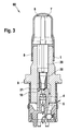
- a conventional solenoid valve in particular for a hydraulic unit, which is used for example in an anti-lock braking system (ABS) or a traction control system (ASR system) or an electronic stability program system (ESP system), is shown in FIG.
- the conventional normally open solenoid valve 60 comprises, in addition to a magnet assembly (not shown), a valve cartridge which comprises a capsule 6, a valve insert 1, a plunger 20 with a sealing cap 21, a return spring 30 and an armature 7.
- the capsule 6 and the valve core 1 of the valve cartridge are joined together by pressing and by a sealing weld 8, the valve cartridge is hydraulically sealed from the atmosphere.
- valve core 1 receives the pressure forces occurring in the hydraulic system and forwards them via a caulking flange 9 to a caulking region (not shown) on a fluid block.
- valve core 1 receives the so-called valve body 4, which comprises a valve seat 10, in which the sealing dome 21 of the plunger 20 sealingly dips to implement the sealing function of the solenoid valve 60.
- the plunger 20 and the return spring 30 are guided in the valve core 1, wherein the plunger 20 is guided in a tappet guide and the return spring 30 is radially guided and centered at one end on the plunger 20 and at the other end rests axially guided on the valve body 4.
- the flow path of the fluid through the solenoid valve is shown schematically by an arrow chain 5.
- the installation location of the return spring 30 is usually in the mainly flow-through space, that is arranged in the region of the flow 5 of the operating medium.
- the spring force of the return spring 30 acts in the region of the flow forces, which act on the turns of the return spring 30 due to the flow.
- the solenoid valve according to the invention with the features of independent claim 1 has the advantage that outside a flow path in a bore of the valve core a support bush is arranged, which receives the return spring, supports and radially leads from the outside. Due to the local separation can be greatly reduced interactions between the return spring and the flow in an advantageous manner, whereby the behavior of the valve is easier to understand and predictable.
- the return spring is radially guided and centered in the valve core by the arrangement in the support bushing from the outside, so that it can be advantageously prevented that the return spring due to force effects, such. Transverse forces, which act on the turns of the return spring, laterally breaks out, or lifts off from a support or the turns of the return spring relative to each other in motion or are set in vibration.
- the support bushing is coupled to the power transmission via a positive connection and / or a frictional connection with the valve core.
- the support bush is inserted into the bore of the valve core and is supported for example by means of positive engagement via a collar on an upper end face of the valve core.
- the support bush can be pressed by means of adhesion into the bore of the valve core, whereby the power transmission between the support bush and the valve core is further improved.
- the support sleeve according to the invention allows the return spring in Advantageously, can be removed from the mainly flowed space and most of the other involved and proven components of the solenoid valve can be adopted unchanged.
- the plunger is adapted to the use of the support bushing.
- the support sleeve comprises means, preferably slots or interruptions, for a volume balance with an armature space.
- the support bush is designed for example as a plastic injection molded part.
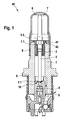
- an exemplary embodiment of a solenoid valve 40 according to the invention analogous to the conventional solenoid valve 60 according to FIG. 3, comprises a valve assembly, not shown, which comprises a capsule 6, a valve insert 1, a plunger 2 with a sealing cap 2.1, a return spring 3 and an anchor 7.
- the capsule 6 and the valve core 1 of the valve cartridge are joined together by pressing and hydraulically sealed by a sealing weld 8 against the atmosphere.
- the valve core 1 receives the pressure forces occurring in the hydraulic system and forwards them via a caulking flange 9 to a caulking region (not shown) on a fluid block.
- valve core 1 receives the so-called valve body 4, which comprises a valve seat 10, in which the sealing cap 2.1 of the plunger 2 is sealingly immersed in order to implement the sealing function of the solenoid valve 40.
- valve body 4 which comprises a valve seat 10, in which the sealing cap 2.1 of the plunger 2 is sealingly immersed in order to implement the sealing function of the solenoid valve 40.
- the flow path of the fluid through the solenoid valve 40 is shown schematically by an arrow chain 5.
- the plunger 2 is movably guided in the valve insert 1 with the sealing dome 2.1.
- the plunger 2 is movable against the spring force of the return spring 3, which is received outside of the flow path 5 of a support bushing 41, supported and radially guided from the outside.
- the support bushing 41 is designed as a plastic injection-molded part and arranged in a bore 1.1 of the valve core 1.
- the support bushing 41 is inserted into the bore 1.1 of the valve core 1 and is supported by positive engagement 42 via a collar on an upper end face 1.2 of the valve core 1 from.
- the support bushing 41 comprises not shown means, preferably slots or interruptions, for a volume balance with an armature space.
- the valve insert 1 receives the valve body 4, which comprises a valve seat 10, in which the sealing dome 2.1 'of the plunger 2' is sealingly immersed in order to implement the sealing function of the solenoid valve 50.
- the flow path of the fluid through the solenoid valve 50 is shown schematically by an arrow chain 5.
- the movably guided in the valve insert 1 plunger 2 'with sealing cap 2.1' is movable against the spring force of the return spring 3, which is taken outside of the flow path 5 of a support bushing 51, supported and guided radially from the outside.
- the support bushing 51 according to FIG. 2 is designed analogously to the support bushing 41 according to FIG. 1 as a plastic injection-molded part and arranged in the bore 1.1 of the valve core 1. In the illustrated embodiment, the support bushing 51 is pressed by means of frictional connection 52 in the bore 1.1 of the valve core 1. Also, the support bush 51 includes means not shown, preferably slots or interruptions, for a volume balance with an armature space.
- the described embodiments of the invention separate the return spring locally from the flow, which can be greatly reduced interactions in an advantageous manner. This allows the behavior of the valve to become easier to understand and predictable.
- the return spring is radially guided and centered in the valve core by the arrangement in the support bushing from the outside, so that it can be advantageously prevented that the return spring due to force effects, such. Transverse forces, which act on the turns of the return spring, laterally breaks out, or lifts off from a support or the turns of the return spring relative to each other in motion or are set in vibration.
Landscapes
- Engineering & Computer Science (AREA)
- Physics & Mathematics (AREA)
- General Engineering & Computer Science (AREA)
- Mechanical Engineering (AREA)
- Electromagnetism (AREA)
- Fluid Mechanics (AREA)
- Transportation (AREA)
- Magnetically Actuated Valves (AREA)
Applications Claiming Priority (1)
| Application Number | Priority Date | Filing Date | Title |
|---|---|---|---|
| DE102006002638A DE102006002638A1 (de) | 2006-01-19 | 2006-01-19 | Magnetventil |
Publications (2)
| Publication Number | Publication Date |
|---|---|
| EP1810902A2 true EP1810902A2 (fr) | 2007-07-25 |
| EP1810902A3 EP1810902A3 (fr) | 2009-11-11 |
Family
ID=37898268
Family Applications (1)
| Application Number | Title | Priority Date | Filing Date |
|---|---|---|---|
| EP07100021A Withdrawn EP1810902A3 (fr) | 2006-01-19 | 2007-01-02 | Electrovanne |
Country Status (3)
| Country | Link |
|---|---|
| US (1) | US20070164244A1 (fr) |
| EP (1) | EP1810902A3 (fr) |
| DE (1) | DE102006002638A1 (fr) |
Cited By (3)
| Publication number | Priority date | Publication date | Assignee | Title |
|---|---|---|---|---|
| WO2009059844A1 (fr) * | 2007-11-08 | 2009-05-14 | Robert Bosch Gmbh | Cartouche pour une électrovanne et électrovanne correspondante |
| WO2011079980A1 (fr) * | 2009-12-28 | 2011-07-07 | Robert Bosch Gmbh | Électrovanne |
| US8623254B2 (en) | 2008-01-21 | 2014-01-07 | Robert Bosch Gmbh | Method and device for producing a magnetic field sensor |
Families Citing this family (15)
| Publication number | Priority date | Publication date | Assignee | Title |
|---|---|---|---|---|
| DE102007053134A1 (de) * | 2007-11-08 | 2009-05-14 | Robert Bosch Gmbh | Ventilpatrone für ein Magnetventil und zugehöriges Magnetventil |
| DE102008042731A1 (de) | 2008-10-10 | 2010-04-15 | Robert Bosch Gmbh | Magnetventil |
| DE102010062262A1 (de) * | 2010-12-01 | 2012-06-06 | Zf Friedrichshafen Ag | Aktuator für eine verstellbare Dämpfventileinrichtung |
| DE102011005487A1 (de) | 2011-03-14 | 2012-09-20 | Robert Bosch Gmbh | Ventileinrichtung, insbesondere Auslassventil einer Kraftstoff-Hochdruckpumpe einer Brennkraftmaschine |
| DE102015109077A1 (de) * | 2015-06-09 | 2016-12-15 | Kendrion (Villingen) Gmbh | Volumenstromgeregeltes Sitzventil |
| KR102744359B1 (ko) * | 2019-04-03 | 2024-12-18 | 이구루코교 가부시기가이샤 | 용량 제어 밸브 |
| EP3951171A4 (fr) | 2019-04-03 | 2022-11-30 | Eagle Industry Co., Ltd. | Soupape de commande de capacité |
| US11821540B2 (en) | 2019-04-03 | 2023-11-21 | Eagle Industry Co., Ltd. | Capacity control valve |
| JP7419349B2 (ja) | 2019-04-03 | 2024-01-22 | イーグル工業株式会社 | 容量制御弁 |
| KR102634942B1 (ko) | 2019-04-24 | 2024-02-08 | 이구루코교 가부시기가이샤 | 용량 제어 밸브 |
| WO2020218284A1 (fr) | 2019-04-24 | 2020-10-29 | イーグル工業株式会社 | Vanne de régulation de capacité |
| EP4141302B1 (fr) | 2020-04-22 | 2025-10-01 | Eagle Industry Co., Ltd. | Soupape de régulation de capacité |
| DE102020206644A1 (de) | 2020-05-27 | 2021-12-02 | Continental Teves Ag & Co. Ohg | Elektromagnetventil, insbesondere für schlupfgeregelte Kraftfahrzeugbremsanlagen |
| DE102021202928A1 (de) | 2021-03-25 | 2022-09-29 | Continental Teves Ag & Co. Ohg | Elektromagnetventil, insbesondere für schlupfgeregelte Kraftfahrzeugbremsanlagen |
| DE102022205221A1 (de) | 2022-05-25 | 2023-11-30 | Continental Automotive Technologies GmbH | Elektromagnetventil für eine Kraftfahrzeugbremsanlage mit Restluftspalteinstellung |
Family Cites Families (27)
| Publication number | Priority date | Publication date | Assignee | Title |
|---|---|---|---|---|
| US771417A (en) * | 1904-04-16 | 1904-10-04 | Burrows Mfg Company | Steam-controlling device. |
| US4538645A (en) * | 1983-08-16 | 1985-09-03 | Ambac Industries, Inc. | Control valve assembly |
| DE3934771C1 (fr) * | 1989-10-18 | 1991-03-28 | Lucas Industries P.L.C., Birmingham, West Midlands, Gb | |
| US5251655A (en) * | 1992-07-06 | 1993-10-12 | Wilshire Partners | Flow control valves for post-mix beverage dispensers |
| JP2838626B2 (ja) * | 1992-09-09 | 1998-12-16 | 日清紡績株式会社 | 電磁弁装置 |
| US5299592A (en) * | 1993-01-08 | 1994-04-05 | Eaton Corporation | High pressure relief system |
| DE4427905A1 (de) * | 1994-08-06 | 1996-02-08 | Teves Gmbh Alfred | Ventilvorrichtung, insbesondere für hydraulische Bremsanlagen mit Blockier- und/oder Antriebsschlupfregelung |
| DE19504246A1 (de) * | 1995-02-09 | 1996-08-14 | Teves Gmbh Alfred | Elektromagnetventil mit Druckbegrenzungsfunktion, insbesondere für hydraulische Kraftfahrzeugbremsanlagen mit Schlupfregelung und/oder automatischem Bremseneingriff zur Fahrdynamikregelung |
| DE19700979A1 (de) * | 1997-01-14 | 1998-07-16 | Teves Gmbh Alfred | Magnetventil |
| JPH10244344A (ja) * | 1997-02-28 | 1998-09-14 | Unisia Jecs Corp | カップ状ソケット部材の成形装置 |
| JP3518294B2 (ja) * | 1997-08-08 | 2004-04-12 | トヨタ自動車株式会社 | 電磁駆動弁 |
| DE19802464A1 (de) * | 1998-01-23 | 1999-07-29 | Bosch Gmbh Robert | Hydraulisches magnetbetätigtes Sitzventil, insbesondere für Bremsanlagen von Kraftfahrzeugen |
| JP2002505408A (ja) * | 1998-03-03 | 2002-02-19 | コンティネンタル・テーベス・アクチエンゲゼルシヤフト・ウント・コンパニー・オッフェネ・ハンデルスゲゼルシヤフト | 電磁弁 |
| JP2002510021A (ja) * | 1998-03-31 | 2002-04-02 | コンチネンタル・テベス・アーゲー・ウント・コンパニー・オーハーゲー | 電磁バルブ |
| DE19849210A1 (de) * | 1998-10-26 | 2000-04-27 | Bosch Gmbh Robert | Brennstoffeinspritzventil |
| US6299130B1 (en) * | 1999-10-14 | 2001-10-09 | Siemens Canada Limited | EEGR valve with flexible bearing |
| EP1232081B1 (fr) * | 1999-11-16 | 2004-02-11 | Continental Teves AG & Co. oHG | Vanne electromagnetique |
| US6390129B2 (en) * | 1999-12-15 | 2002-05-21 | Jansen's Aircraft Systems Controls, Inc. | Proportional solenoid-operated fluid metering device |
| US6390444B1 (en) * | 2000-01-14 | 2002-05-21 | Delphi Technologies, Inc. | Two-stage parallel spring solenoid valve |
| GB0005825D0 (en) * | 2000-03-11 | 2000-05-03 | Archfact Ltd | Compressor spring locator |
| JP2001303915A (ja) * | 2000-04-18 | 2001-10-31 | Nissan Motor Co Ltd | 内燃機関の動弁装置 |
| US6386220B1 (en) * | 2000-05-22 | 2002-05-14 | Eaton Corporation | Solenoid operated pressure control valve |
| DE10109411A1 (de) * | 2001-02-28 | 2002-09-05 | Bosch Gmbh Robert | Brennstoffeinspritzventil |
| JP3857128B2 (ja) * | 2001-12-21 | 2006-12-13 | 三菱電機株式会社 | 流量制御弁 |
| DE102004030425A1 (de) * | 2004-06-24 | 2006-01-19 | Robert Bosch Gmbh | Ventilvorrichtung |
| DE102004030424A1 (de) * | 2004-06-24 | 2006-01-19 | Robert Bosch Gmbh | Ventilvorrichtung |
| DE102005044672A1 (de) * | 2005-09-19 | 2007-03-22 | Robert Bosch Gmbh | Magnetventil |
-
2006
- 2006-01-19 DE DE102006002638A patent/DE102006002638A1/de not_active Withdrawn
-
2007
- 2007-01-02 EP EP07100021A patent/EP1810902A3/fr not_active Withdrawn
- 2007-01-17 US US11/653,985 patent/US20070164244A1/en not_active Abandoned
Non-Patent Citations (1)
| Title |
|---|
| None |
Cited By (7)
| Publication number | Priority date | Publication date | Assignee | Title |
|---|---|---|---|---|
| WO2009059844A1 (fr) * | 2007-11-08 | 2009-05-14 | Robert Bosch Gmbh | Cartouche pour une électrovanne et électrovanne correspondante |
| US8424840B2 (en) | 2007-11-08 | 2013-04-23 | Robert Bosch Gmbh | Valve cartridge for a solenoid valve, and associated solenoid valve |
| US8623254B2 (en) | 2008-01-21 | 2014-01-07 | Robert Bosch Gmbh | Method and device for producing a magnetic field sensor |
| WO2011079980A1 (fr) * | 2009-12-28 | 2011-07-07 | Robert Bosch Gmbh | Électrovanne |
| CN102686463A (zh) * | 2009-12-28 | 2012-09-19 | 罗伯特·博世有限公司 | 电磁阀 |
| US9074701B2 (en) | 2009-12-28 | 2015-07-07 | Robert Bosch Gmbh | Solenoid valve |
| CN102686463B (zh) * | 2009-12-28 | 2015-09-02 | 罗伯特·博世有限公司 | 电磁阀 |
Also Published As
| Publication number | Publication date |
|---|---|
| US20070164244A1 (en) | 2007-07-19 |
| EP1810902A3 (fr) | 2009-11-11 |
| DE102006002638A1 (de) | 2007-07-26 |
Similar Documents
| Publication | Publication Date | Title |
|---|---|---|
| EP1810902A2 (fr) | Electrovanne | |
| EP2091797B1 (fr) | Électrovanne | |
| EP1928714B1 (fr) | Electrovanne | |
| DE102007007784B4 (de) | Magnetventil | |
| WO2009019094A1 (fr) | Soupape magnétique | |
| EP2114740B1 (fr) | Soupape magnétique | |
| WO2008058802A1 (fr) | Électrovanne | |
| DE102007053300A1 (de) | Magnetventil | |
| DE102015218263A1 (de) | Magnetventil | |
| EP2170665B1 (fr) | Électrovanne | |
| WO2008151867A1 (fr) | Électrovanne | |
| EP1816047A2 (fr) | Soupape magnétique | |
| WO2008151904A1 (fr) | Électrovanne | |
| DE102012213761A1 (de) | Ventilkörper für ein Stellventil und korrespondierendes Magnetventil | |
| DE102006052629B4 (de) | Magnetventil | |
| EP1911999A1 (fr) | Corps de soupape et soupape magnétique correspondante | |
| EP1981745A1 (fr) | Électrovanne | |
| DE10332348A1 (de) | Brennstoffeinspritzventil | |
| DE19815778A1 (de) | Absperrventil mit Druckbegrenzungsfunktion, insbesondere für schlupfgeregelte hydraulische Bremsanlagen von Kraftfahrzeugen | |
| DE102004056892A1 (de) | Elektromagnetisch betätigbares Ventil, insbesondere in einer Bremsanlage eines Kraftfahrzeuges | |
| DE102012209729A1 (de) | Magnetventil | |
| EP1813490B1 (fr) | Electrovanne | |
| EP2338750B1 (fr) | Soupape magnétique et dispositif d'assistance au conducteur | |
| EP1810903B1 (fr) | Electrovanne | |
| DE202005013233U1 (de) | Magnetventil-System |
Legal Events
| Date | Code | Title | Description |
|---|---|---|---|
| PUAI | Public reference made under article 153(3) epc to a published international application that has entered the european phase |
Free format text: ORIGINAL CODE: 0009012 |
|
| AK | Designated contracting states |
Kind code of ref document: A2 Designated state(s): AT BE BG CH CY CZ DE DK EE ES FI FR GB GR HU IE IS IT LI LT LU LV MC NL PL PT RO SE SI SK TR |
|
| AX | Request for extension of the european patent |
Extension state: AL BA HR MK YU |
|
| PUAL | Search report despatched |
Free format text: ORIGINAL CODE: 0009013 |
|
| AK | Designated contracting states |
Kind code of ref document: A3 Designated state(s): AT BE BG CH CY CZ DE DK EE ES FI FR GB GR HU IE IS IT LI LT LU LV MC NL PL PT RO SE SI SK TR |
|
| AX | Request for extension of the european patent |
Extension state: AL BA HR MK RS |
|
| AKX | Designation fees paid | ||
| STAA | Information on the status of an ep patent application or granted ep patent |
Free format text: STATUS: THE APPLICATION IS DEEMED TO BE WITHDRAWN |
|
| 18D | Application deemed to be withdrawn |
Effective date: 20101112 |
|
| REG | Reference to a national code |
Ref country code: DE Ref legal event code: 8566 |