EP1810902A2 - Solenoid valve - Google Patents
Solenoid valve Download PDFInfo
- Publication number
- EP1810902A2 EP1810902A2 EP07100021A EP07100021A EP1810902A2 EP 1810902 A2 EP1810902 A2 EP 1810902A2 EP 07100021 A EP07100021 A EP 07100021A EP 07100021 A EP07100021 A EP 07100021A EP 1810902 A2 EP1810902 A2 EP 1810902A2
- Authority
- EP
- European Patent Office
- Prior art keywords
- valve
- solenoid valve
- return spring
- valve core
- support
- Prior art date
- Legal status (The legal status is an assumption and is not a legal conclusion. Google has not performed a legal analysis and makes no representation as to the accuracy of the status listed.)
- Withdrawn
Links
- 238000007789 sealing Methods 0.000 claims abstract description 19
- 239000002775 capsule Substances 0.000 description 5
- 239000012530 fluid Substances 0.000 description 5
- 230000000694 effects Effects 0.000 description 3
- 230000005540 biological transmission Effects 0.000 description 2
- 238000009434 installation Methods 0.000 description 2
- 230000003993 interaction Effects 0.000 description 2
- 230000002411 adverse Effects 0.000 description 1
- 230000001419 dependent effect Effects 0.000 description 1
- 238000002347 injection Methods 0.000 description 1
- 239000007924 injection Substances 0.000 description 1
- 238000004519 manufacturing process Methods 0.000 description 1
- 238000000926 separation method Methods 0.000 description 1
- 238000004804 winding Methods 0.000 description 1
Images

Classifications
-
- B—PERFORMING OPERATIONS; TRANSPORTING
- B60—VEHICLES IN GENERAL
- B60T—VEHICLE BRAKE CONTROL SYSTEMS OR PARTS THEREOF; BRAKE CONTROL SYSTEMS OR PARTS THEREOF, IN GENERAL; ARRANGEMENT OF BRAKING ELEMENTS ON VEHICLES IN GENERAL; PORTABLE DEVICES FOR PREVENTING UNWANTED MOVEMENT OF VEHICLES; VEHICLE MODIFICATIONS TO FACILITATE COOLING OF BRAKES
- B60T8/00—Arrangements for adjusting wheel-braking force to meet varying vehicular or ground-surface conditions, e.g. limiting or varying distribution of braking force
- B60T8/32—Arrangements for adjusting wheel-braking force to meet varying vehicular or ground-surface conditions, e.g. limiting or varying distribution of braking force responsive to a speed condition, e.g. acceleration or deceleration
- B60T8/34—Arrangements for adjusting wheel-braking force to meet varying vehicular or ground-surface conditions, e.g. limiting or varying distribution of braking force responsive to a speed condition, e.g. acceleration or deceleration having a fluid pressure regulator responsive to a speed condition
- B60T8/36—Arrangements for adjusting wheel-braking force to meet varying vehicular or ground-surface conditions, e.g. limiting or varying distribution of braking force responsive to a speed condition, e.g. acceleration or deceleration having a fluid pressure regulator responsive to a speed condition including a pilot valve responding to an electromagnetic force
- B60T8/3615—Electromagnetic valves specially adapted for anti-lock brake and traction control systems
- B60T8/363—Electromagnetic valves specially adapted for anti-lock brake and traction control systems in hydraulic systems
-
- F—MECHANICAL ENGINEERING; LIGHTING; HEATING; WEAPONS; BLASTING
- F16—ENGINEERING ELEMENTS AND UNITS; GENERAL MEASURES FOR PRODUCING AND MAINTAINING EFFECTIVE FUNCTIONING OF MACHINES OR INSTALLATIONS; THERMAL INSULATION IN GENERAL
- F16K—VALVES; TAPS; COCKS; ACTUATING-FLOATS; DEVICES FOR VENTING OR AERATING
- F16K31/00—Actuating devices; Operating means; Releasing devices
- F16K31/02—Actuating devices; Operating means; Releasing devices electric; magnetic
- F16K31/06—Actuating devices; Operating means; Releasing devices electric; magnetic using a magnet, e.g. diaphragm valves, cutting off by means of a liquid
- F16K31/0644—One-way valve
- F16K31/0655—Lift valves
- F16K31/0658—Armature and valve member being one single element
-
- F—MECHANICAL ENGINEERING; LIGHTING; HEATING; WEAPONS; BLASTING
- F16—ENGINEERING ELEMENTS AND UNITS; GENERAL MEASURES FOR PRODUCING AND MAINTAINING EFFECTIVE FUNCTIONING OF MACHINES OR INSTALLATIONS; THERMAL INSULATION IN GENERAL
- F16K—VALVES; TAPS; COCKS; ACTUATING-FLOATS; DEVICES FOR VENTING OR AERATING
- F16K31/00—Actuating devices; Operating means; Releasing devices
- F16K31/02—Actuating devices; Operating means; Releasing devices electric; magnetic
- F16K31/06—Actuating devices; Operating means; Releasing devices electric; magnetic using a magnet, e.g. diaphragm valves, cutting off by means of a liquid
- F16K31/0686—Braking, pressure equilibration, shock absorbing
- F16K31/0693—Pressure equilibration of the armature
Definitions
- the invention relates to a solenoid valve according to the preamble of independent claim 1.
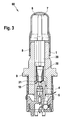
- a conventional solenoid valve in particular for a hydraulic unit, which is used for example in an anti-lock braking system (ABS) or a traction control system (ASR system) or an electronic stability program system (ESP system), is shown in FIG.
- the conventional normally open solenoid valve 60 comprises, in addition to a magnet assembly (not shown), a valve cartridge which comprises a capsule 6, a valve insert 1, a plunger 20 with a sealing cap 21, a return spring 30 and an armature 7.
- the capsule 6 and the valve core 1 of the valve cartridge are joined together by pressing and by a sealing weld 8, the valve cartridge is hydraulically sealed from the atmosphere.
- valve core 1 receives the pressure forces occurring in the hydraulic system and forwards them via a caulking flange 9 to a caulking region (not shown) on a fluid block.
- valve core 1 receives the so-called valve body 4, which comprises a valve seat 10, in which the sealing dome 21 of the plunger 20 sealingly dips to implement the sealing function of the solenoid valve 60.
- the plunger 20 and the return spring 30 are guided in the valve core 1, wherein the plunger 20 is guided in a tappet guide and the return spring 30 is radially guided and centered at one end on the plunger 20 and at the other end rests axially guided on the valve body 4.
- the flow path of the fluid through the solenoid valve is shown schematically by an arrow chain 5.
- the installation location of the return spring 30 is usually in the mainly flow-through space, that is arranged in the region of the flow 5 of the operating medium.
- the spring force of the return spring 30 acts in the region of the flow forces, which act on the turns of the return spring 30 due to the flow.
- the solenoid valve according to the invention with the features of independent claim 1 has the advantage that outside a flow path in a bore of the valve core a support bush is arranged, which receives the return spring, supports and radially leads from the outside. Due to the local separation can be greatly reduced interactions between the return spring and the flow in an advantageous manner, whereby the behavior of the valve is easier to understand and predictable.
- the return spring is radially guided and centered in the valve core by the arrangement in the support bushing from the outside, so that it can be advantageously prevented that the return spring due to force effects, such. Transverse forces, which act on the turns of the return spring, laterally breaks out, or lifts off from a support or the turns of the return spring relative to each other in motion or are set in vibration.
- the support bushing is coupled to the power transmission via a positive connection and / or a frictional connection with the valve core.
- the support bush is inserted into the bore of the valve core and is supported for example by means of positive engagement via a collar on an upper end face of the valve core.
- the support bush can be pressed by means of adhesion into the bore of the valve core, whereby the power transmission between the support bush and the valve core is further improved.
- the support sleeve according to the invention allows the return spring in Advantageously, can be removed from the mainly flowed space and most of the other involved and proven components of the solenoid valve can be adopted unchanged.
- the plunger is adapted to the use of the support bushing.
- the support sleeve comprises means, preferably slots or interruptions, for a volume balance with an armature space.
- the support bush is designed for example as a plastic injection molded part.
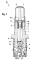
- an exemplary embodiment of a solenoid valve 40 according to the invention analogous to the conventional solenoid valve 60 according to FIG. 3, comprises a valve assembly, not shown, which comprises a capsule 6, a valve insert 1, a plunger 2 with a sealing cap 2.1, a return spring 3 and an anchor 7.
- the capsule 6 and the valve core 1 of the valve cartridge are joined together by pressing and hydraulically sealed by a sealing weld 8 against the atmosphere.
- the valve core 1 receives the pressure forces occurring in the hydraulic system and forwards them via a caulking flange 9 to a caulking region (not shown) on a fluid block.
- valve core 1 receives the so-called valve body 4, which comprises a valve seat 10, in which the sealing cap 2.1 of the plunger 2 is sealingly immersed in order to implement the sealing function of the solenoid valve 40.
- valve body 4 which comprises a valve seat 10, in which the sealing cap 2.1 of the plunger 2 is sealingly immersed in order to implement the sealing function of the solenoid valve 40.
- the flow path of the fluid through the solenoid valve 40 is shown schematically by an arrow chain 5.
- the plunger 2 is movably guided in the valve insert 1 with the sealing dome 2.1.
- the plunger 2 is movable against the spring force of the return spring 3, which is received outside of the flow path 5 of a support bushing 41, supported and radially guided from the outside.
- the support bushing 41 is designed as a plastic injection-molded part and arranged in a bore 1.1 of the valve core 1.
- the support bushing 41 is inserted into the bore 1.1 of the valve core 1 and is supported by positive engagement 42 via a collar on an upper end face 1.2 of the valve core 1 from.
- the support bushing 41 comprises not shown means, preferably slots or interruptions, for a volume balance with an armature space.
- the valve insert 1 receives the valve body 4, which comprises a valve seat 10, in which the sealing dome 2.1 'of the plunger 2' is sealingly immersed in order to implement the sealing function of the solenoid valve 50.
- the flow path of the fluid through the solenoid valve 50 is shown schematically by an arrow chain 5.
- the movably guided in the valve insert 1 plunger 2 'with sealing cap 2.1' is movable against the spring force of the return spring 3, which is taken outside of the flow path 5 of a support bushing 51, supported and guided radially from the outside.
- the support bushing 51 according to FIG. 2 is designed analogously to the support bushing 41 according to FIG. 1 as a plastic injection-molded part and arranged in the bore 1.1 of the valve core 1. In the illustrated embodiment, the support bushing 51 is pressed by means of frictional connection 52 in the bore 1.1 of the valve core 1. Also, the support bush 51 includes means not shown, preferably slots or interruptions, for a volume balance with an armature space.
- the described embodiments of the invention separate the return spring locally from the flow, which can be greatly reduced interactions in an advantageous manner. This allows the behavior of the valve to become easier to understand and predictable.
- the return spring is radially guided and centered in the valve core by the arrangement in the support bushing from the outside, so that it can be advantageously prevented that the return spring due to force effects, such. Transverse forces, which act on the turns of the return spring, laterally breaks out, or lifts off from a support or the turns of the return spring relative to each other in motion or are set in vibration.
Landscapes
- Engineering & Computer Science (AREA)
- Physics & Mathematics (AREA)
- General Engineering & Computer Science (AREA)
- Mechanical Engineering (AREA)
- Electromagnetism (AREA)
- Fluid Mechanics (AREA)
- Transportation (AREA)
- Magnetically Actuated Valves (AREA)
Abstract
Description
Die Erfindung geht aus von einem Magnetventil nach der Gattung des unabhängigen Patentanspruchs 1.The invention relates to a solenoid valve according to the preamble of
Ein herkömmliches Magnetventil, insbesondere für ein Hydraulikaggregat, welches beispielsweise in einem Antiblockiersystem (ABS) oder einem Antriebsschlupfregelsystem (ASR-System) oder einem elektronischen Stabilitätsprogrammsystem (ESP-System) eingesetzt wird, ist in Figur 3 dargestellt. Wie aus Figur 3 ersichtlich ist, umfasst das herkömmliche stromlos offene Magnetventil 60 neben einer nicht dargestellten Magnetbaugruppe eine Ventilpatrone, welche eine Kapsel 6, einen Ventileinsatz 1, einen Stößel 20 mit einer Dichtkalotte 21, eine Rückstellfeder 30 und einen Anker 7 umfasst. Bei der Herstellung des Magnetventils 60 werden die Kapsel 6 und der Ventileinsatz 1 der Ventilpatrone durch Pressen aufeinander gefügt und durch eine Dichtschweißung 8 wird die Ventilpatrone hydraulisch gegenüber der Atmosphäre abgedichtet. Zusätzlich nimmt der Ventileinsatz 1 die im hydraulischen System auftretenden Druckkräfte auf und leitet diese über einen Verstemmflansch 9 an einen nicht dargestellten Verstemmbereich auf einem Fluidblock weiter. Zudem nimmt der Ventileinsatz 1 den so genannten Ventilkörper 4 auf, welcher einen Ventilsitz 10 umfasst, in welchen der die Dichtkalotte 21 des Stößels 20 dichtend eintaucht, um die Dichtfunktion des Magnetventils 60 umzusetzen. Wie weiter aus Figur 3 ersichtlich ist, werden der Stößel 20 und die Rückstellfeder 30 im Ventileinsatz 1 geführt, wobei der Stößel 20 in einer Stößelführung geführt ist und die Rückstellfeder 30 an einem Ende auf dem Stößel 20 radial geführt und zentriert ist und am anderen Ende auf dem Ventilkörper 4 axial geführt aufliegt. Der Strömungsweg des Fluids durch das Magnetventil ist schematisch durch eine Pfeilkette 5 dargestellt. Wegen der einfachen Montage ist der Einbauort der Rückstellfeder 30 meist im hauptsächlich durchströmten Raum, d.h. im Bereich der Durchströmung 5 des Betriebsmediums angeordnet. Somit wirkt die Federkraft der Rückstellfeder 30 im Bereich der Strömungskräfte, welche aufgrund der Strömung auf die Windungen der Rückstellfeder 30 wirken.A conventional solenoid valve, in particular for a hydraulic unit, which is used for example in an anti-lock braking system (ABS) or a traction control system (ASR system) or an electronic stability program system (ESP system), is shown in FIG. As can be seen from FIG. 3, the conventional normally
Dadurch kann es zu einer unerwünschten Beeinflussung des Federverhaltens durch die Strömung kommen. Diese Einflüsse können z.B. Strömungs- und Umlenkkräfte an den Federwindungen, veränderliche Strömung an veränderlichen Windungsabständen usw. sein. Diese Einflüsse sind unbekannt, veränderlich und schwer zu berechnen. So kann es beispielsweise zum Abheben der Rückstellfeder 30 von ihrer Auflage am Ventilkörper 4 kommen, was mit einer entsprechenden (Kraft-)Wirkung auf den Ventilstößel 20 und einer unerwünschter Beeinflussung der Ventilfunktion verbunden sein kann. Des Weiteren kann die ungeführte Rückstellfeder 30 seitlich ausgelenkt oder versetzt werden, so dass es zu Berührungen und damit zu Reibkräften zwischen dem Ventileinsatz 1 und dem Stößel 20 kommen kann. Durch die erzeugten Reibkräfte kann das Ventilverhalten negativ beeinflusst werden und der Stößel 20 kann durch die evtl. gratbehafteten Federenden beschädigt werden.This can lead to an undesirable influence of the spring behavior by the flow. These influences can be e.g. Flow and deflection forces on the spring coils, variable flow at variable winding distances, etc. be. These influences are unknown, changeable and difficult to calculate. Thus, for example, to lift off the
Das erfindungsgemäße Magnetventil mit den Merkmalen des unabhängigen Patentanspruchs 1 hat demgegenüber den Vorteil, dass außerhalb eines Strömungswegs in einer Bohrung des Ventileinsatzes eine Abstützbuchse angeordnet ist, welche die Rückstellfeder aufnimmt, abstützt und von außen radial führt. Durch die örtliche Trennung können in vorteilhafter Weise Wechselwirkungen zwischen der Rückstellfeder und der Strömung stark verringert werden, wodurch das Verhalten des Ventils einfacher verständlich und vorhersehbar wird. Zudem wird die Rückstellfeder durch die Anordnung in der Abstützbuchse von außen radial im Ventileinsatz geführt und zentriert, so dass in vorteilhafter Weise verhindert werden kann, dass die Rückstellfeder aufgrund von Kraftwirkungen, wie z.B. Querkräften, welche auf die Windungen der Rückstellfeder wirken, seitlich ausbricht, oder von einer Auflage abhebt bzw. die Windungen der Rückstellfeder relativ zueinander in Bewegung bzw. in Schwingungen versetzt werden.The solenoid valve according to the invention with the features of
Durch die in den abhängigen Ansprüchen aufgeführten Maßnahmen und Weiterbildungen sind vorteilhafte Verbesserungen des im unabhängigen Patentanspruch angegebenen Magnetventils möglich.The measures and refinements recited in the dependent claims advantageous improvements of the independent claim solenoid valve are possible.
Besonders vorteilhaft ist, dass die Abstützbuchse zur Kraftübertragung über einen Formschluss und/oder einen Kraftschluss mit dem Ventileinsatz gekoppelt ist. So ist die Abstützbuchse in die Bohrung des Ventileinsatzes eingeführt und stützt sich beispielsweise mittels Formschluss über einen Bund auf einer oberen Stirnfläche des Ventileinsatzes ab. Zusätzlich oder alternativ kann die Abstützbuchse mittels Kraftschluss in die Bohrung des Ventileinsatzes eingepresst werden, wodurch die Kraftübertragung zwischen der Abstützbuchse und dem Ventileinsatz weiter verbessert wird. Die erfindungsgemäße Abstützbuchse ermöglicht, dass die Rückstellfeder in vorteilhafter Weise aus dem hauptsächlich durchströmten Raum entfernt werden kann und die meisten der anderen beteiligten und bewährten Komponenten des Magnetventils unverändert übernommen werden können. Im Wesentlichen wird der Stößel an die Verwendung der Abstützbuchse angepasst.It is particularly advantageous that the support bushing is coupled to the power transmission via a positive connection and / or a frictional connection with the valve core. Thus, the support bush is inserted into the bore of the valve core and is supported for example by means of positive engagement via a collar on an upper end face of the valve core. Additionally or alternatively, the support bush can be pressed by means of adhesion into the bore of the valve core, whereby the power transmission between the support bush and the valve core is further improved. The support sleeve according to the invention allows the return spring in Advantageously, can be removed from the mainly flowed space and most of the other involved and proven components of the solenoid valve can be adopted unchanged. Essentially, the plunger is adapted to the use of the support bushing.
In Ausgestaltung des erfindungsgemäßen Magnetventils umfasst die Abstützbuchse Mittel, vorzugsweise Schlitze oder Unterbrechungen, für einen Volumenausgleich mit einem Ankerraum. Die Abstützbuchse ist beispielsweise als Kunststoffspritzteil ausgeführt.In an embodiment of the solenoid valve according to the invention, the support sleeve comprises means, preferably slots or interruptions, for a volume balance with an armature space. The support bush is designed for example as a plastic injection molded part.
Vorteilhafte, nachfolgend beschriebene Ausführungsformen der Erfindung sowie das zu deren besserem Verständnis oben erläuterte, herkömmliche Ausführungsbeispiel sind in den Zeichnungen dargestellt. Es zeigen:
Figur 1- eine schematische Schnittdarstellung eines Ausführungsbeispiels eines erfindungsgemäßen Magnetventils,
Figur 2- eine schematische Schnittdarstellung eines weiteren Ausführungsbeispiels eines erfindungsgemäßen Magnetventils, und
Figur 3- eine schematische Schnittdarstellung eines herkömmlichen Magnetventils.
- FIG. 1
- a schematic sectional view of an embodiment of a solenoid valve according to the invention,
- FIG. 2
- a schematic sectional view of another embodiment of a solenoid valve according to the invention, and
- FIG. 3
- a schematic sectional view of a conventional solenoid valve.
Wie aus Figur 1 ersichtlich ist, umfasst ein Ausführungsbeispiel eines erfindungsgemäßen Magnetventils 40 analog zum herkömmlichen Magnetventil 60 gemäß Figur 3 neben einer nicht dargestellten Magnetbaugruppe eine Ventilpatrone, welche eine Kapsel 6, einen Ventileinsatz 1, einen Stößel 2 mit einer Dichtkalotte 2.1, eine Rückstellfeder 3 und einen Anker 7 umfasst. Die Kapsel 6 und der Ventileinsatz 1 der Ventilpatrone werden durch Pressen aufeinander gefügt und durch eine Dichtschweißung 8 hydraulisch gegenüber der Atmosphäre abgedichtet. Zusätzlich nimmt der Ventileinsatz 1 die im hydraulischen System auftretenden Druckkräfte auf und leitet diese über einen Verstemmflansch 9 an einen nicht dargestellten Verstemmbereich auf einem Fluidblock weiter. Zudem nimmt der Ventileinsatz 1 den so genannten Ventilkörper 4 auf, welcher einen Ventilsitz 10 umfasst, in welchen die Dichtkalotte 2.1 des Stößels 2 dichtend eintaucht, um die Dichtfunktion des Magnetventils 40 umzusetzen. Der Strömungsweg des Fluids durch das Magnetventil 40 ist schematisch durch eine Pfeilkette 5 dargestellt.As can be seen from FIG. 1, an exemplary embodiment of a
Wie weiter aus Figur 1 ersichtlich ist, ist der Stößel 2 mit der Dichtkalotte 2.1 beweglich im Ventileinsatz 1 geführt. Der Stößel 2 ist gegen die Federkraft der Rückstellfeder 3 bewegbar, welche außerhalb des Strömungswegs 5 von einer Abstützbuchse 41 aufgenommen, abgestützt und von außen radial geführt wird. Die Abstützbuchse 41 ist als Kunststoffspritzteil ausgeführt und in einer Bohrung 1.1 des Ventileinsatzes 1 angeordnet. Im dargestellten Ausführungsbeispiel ist die Abstützbuchse 41 in die Bohrung 1.1 des Ventileinsatzes 1 eingeführt und stützt sich mittels Formschluss 42 über einen Bund auf einer oberen Stirnfläche 1.2 des Ventileinsatzes 1 ab. Zudem umfasst die Abstützbuchse 41 nicht dargestellte Mittel, vorzugsweise Schlitze oder Unterbrechungen, für einen Volumenausgleich mit einem Ankerraum.As can be seen further from FIG. 1, the
Wie aus Figur 2 ersichtlich ist, umfasst ein anderes Ausführungsbeispiel eines erfindungsgemäßen Magnetventils 50 analog zum erfindungsgemäßen Magnetventil 40 gemäß Figur 1 neben einer nicht dargestellten Magnetbaugruppe eine Ventilpatrone, welche eine Kapsel 6, einen Ventileinsatz 1, einen Stößel 2' mit einer Dichtkalotte 2.1', eine Rückstellfeder 3 und einen Anker 7 umfasst. Der Ventileinsatz 1 nimmt den Ventilkörper 4 auf, welcher einen Ventilsitz 10 umfasst, in welchen die Dichtkalotte 2.1' des Stößels 2' dichtend eintaucht, um die Dichtfunktion des Magnetventils 50 umzusetzen. Der Strömungsweg des Fluids durch das Magnetventil 50 ist schematisch durch eine Pfeilkette 5 dargestellt. Der beweglich im Ventileinsatz 1 geführte Stößel 2' mit Dichtkalotte 2.1' ist gegen die Federkraft der Rückstellfeder 3 bewegbar, welche außerhalb des Strömungswegs 5 von einer Abstützbuchse 51 aufgenommen, abgestützt und von außen radial geführt wird. Die Abstützbuchse 51 gemäß Figur 2 ist analog zur Abstützbuchse 41 gemäße Figur 1 als Kunststoffspritzteil ausgeführt und in der Bohrung 1.1 des Ventileinsatzes 1 angeordnet. Im dargestellten Ausführungsbeispiel ist die Abstützbuchse 51 mittels Kraftschluss 52 in die Bohrung 1.1 des Ventileinsatzes 1 eingepresst. Auch die Abstützbuchse 51 umfasst nicht dargestellte Mittel, vorzugsweise Schlitze oder Unterbrechungen, für einen Volumenausgleich mit einem Ankerraum.As can be seen from FIG. 2, another embodiment of a
Die beschriebenen erfindungsgemäßen Ausführungsformen trennen die Rückstellfeder örtlich von der Strömung, wodurch in vorteilhafter Weise Wechselwirkungen stark verringert werden können. Dies ermöglicht, dass das Verhalten des Ventils einfacher verständlich und vorhersehbar wird. Zudem wird die Rückstellfeder durch die Anordnung in der Abstützbuchse von außen radial im Ventileinsatz geführt und zentriert, so dass in vorteilhafter Weise verhindert werden kann, dass die Rückstellfeder aufgrund von Kraftwirkungen, wie z.B. Querkräften, welche auf die Windungen der Rückstellfeder wirken, seitlich ausbricht, oder von einer Auflage abhebt bzw. die Windungen der Rückstellfeder relativ zueinander in Bewegung bzw. in Schwingungen versetzt werden.The described embodiments of the invention separate the return spring locally from the flow, which can be greatly reduced interactions in an advantageous manner. This allows the behavior of the valve to become easier to understand and predictable. In addition, the return spring is radially guided and centered in the valve core by the arrangement in the support bushing from the outside, so that it can be advantageously prevented that the return spring due to force effects, such. Transverse forces, which act on the turns of the return spring, laterally breaks out, or lifts off from a support or the turns of the return spring relative to each other in motion or are set in vibration.
Claims (6)
Applications Claiming Priority (1)
| Application Number | Priority Date | Filing Date | Title |
|---|---|---|---|
| DE102006002638A DE102006002638A1 (en) | 2006-01-19 | 2006-01-19 | magnetic valve |
Publications (2)
| Publication Number | Publication Date |
|---|---|
| EP1810902A2 true EP1810902A2 (en) | 2007-07-25 |
| EP1810902A3 EP1810902A3 (en) | 2009-11-11 |
Family
ID=37898268
Family Applications (1)
| Application Number | Title | Priority Date | Filing Date |
|---|---|---|---|
| EP07100021A Withdrawn EP1810902A3 (en) | 2006-01-19 | 2007-01-02 | Solenoid valve |
Country Status (3)
| Country | Link |
|---|---|
| US (1) | US20070164244A1 (en) |
| EP (1) | EP1810902A3 (en) |
| DE (1) | DE102006002638A1 (en) |
Cited By (3)
| Publication number | Priority date | Publication date | Assignee | Title |
|---|---|---|---|---|
| WO2009059844A1 (en) * | 2007-11-08 | 2009-05-14 | Robert Bosch Gmbh | Valve cartridge for a solenoid valve, and associated solenoid valve |
| WO2011079980A1 (en) * | 2009-12-28 | 2011-07-07 | Robert Bosch Gmbh | Solenoid valve |
| US8623254B2 (en) | 2008-01-21 | 2014-01-07 | Robert Bosch Gmbh | Method and device for producing a magnetic field sensor |
Families Citing this family (15)
| Publication number | Priority date | Publication date | Assignee | Title |
|---|---|---|---|---|
| DE102007053134A1 (en) * | 2007-11-08 | 2009-05-14 | Robert Bosch Gmbh | Valve cartridge for a solenoid valve and associated solenoid valve |
| DE102008042731A1 (en) | 2008-10-10 | 2010-04-15 | Robert Bosch Gmbh | magnetic valve |
| DE102010062262A1 (en) * | 2010-12-01 | 2012-06-06 | Zf Friedrichshafen Ag | Actuator for an adjustable damping valve device |
| DE102011005487A1 (en) | 2011-03-14 | 2012-09-20 | Robert Bosch Gmbh | Valve device, in particular outlet valve of a high-pressure fuel pump of an internal combustion engine |
| DE102015109077A1 (en) * | 2015-06-09 | 2016-12-15 | Kendrion (Villingen) Gmbh | Flow controlled seat valve |
| JP7423169B2 (en) | 2019-04-03 | 2024-01-29 | イーグル工業株式会社 | capacity control valve |
| US12072035B2 (en) * | 2019-04-03 | 2024-08-27 | Eagle Industry Co., Ltd. | Capacity control valve |
| EP3951170B1 (en) | 2019-04-03 | 2025-02-19 | Eagle Industry Co., Ltd. | Capacity control valve |
| EP3951174B1 (en) | 2019-04-03 | 2025-03-05 | Eagle Industry Co., Ltd. | Capacity control valve |
| US12031531B2 (en) | 2019-04-24 | 2024-07-09 | Eagle Industry Co., Ltd. | Capacity control valve |
| JP7451064B2 (en) | 2019-04-24 | 2024-03-18 | イーグル工業株式会社 | capacity control valve |
| EP4141302B1 (en) | 2020-04-22 | 2025-10-01 | Eagle Industry Co., Ltd. | Capacity control valve |
| DE102020206644A1 (en) | 2020-05-27 | 2021-12-02 | Continental Teves Ag & Co. Ohg | Electromagnetic valve, in particular for slip-regulated motor vehicle brake systems |
| DE102021202928A1 (en) | 2021-03-25 | 2022-09-29 | Continental Teves Ag & Co. Ohg | Electromagnetic valve, in particular for slip-controlled motor vehicle brake systems |
| DE102022205221A1 (en) | 2022-05-25 | 2023-11-30 | Continental Automotive Technologies GmbH | Electromagnetic valve for a motor vehicle brake system with residual air gap adjustment |
Family Cites Families (27)
| Publication number | Priority date | Publication date | Assignee | Title |
|---|---|---|---|---|
| US771417A (en) * | 1904-04-16 | 1904-10-04 | Burrows Mfg Company | Steam-controlling device. |
| US4538645A (en) * | 1983-08-16 | 1985-09-03 | Ambac Industries, Inc. | Control valve assembly |
| DE3934771C1 (en) * | 1989-10-18 | 1991-03-28 | Lucas Industries P.L.C., Birmingham, West Midlands, Gb | |
| US5251655A (en) * | 1992-07-06 | 1993-10-12 | Wilshire Partners | Flow control valves for post-mix beverage dispensers |
| JP2838626B2 (en) * | 1992-09-09 | 1998-12-16 | 日清紡績株式会社 | Solenoid valve device |
| US5299592A (en) * | 1993-01-08 | 1994-04-05 | Eaton Corporation | High pressure relief system |
| DE4427905A1 (en) * | 1994-08-06 | 1996-02-08 | Teves Gmbh Alfred | Valve device, in particular for hydraulic brake systems with blocking and / or traction control |
| DE19504246A1 (en) * | 1995-02-09 | 1996-08-14 | Teves Gmbh Alfred | Solenoid valve with pressure limiting function, especially for hydraulic motor vehicle brake systems with slip control and / or automatic brake intervention for driving dynamics control |
| DE19700979A1 (en) * | 1997-01-14 | 1998-07-16 | Teves Gmbh Alfred | magnetic valve |
| JPH10244344A (en) * | 1997-02-28 | 1998-09-14 | Unisia Jecs Corp | Molding equipment for cup-shaped socket members |
| JP3518294B2 (en) * | 1997-08-08 | 2004-04-12 | トヨタ自動車株式会社 | Solenoid driven valve |
| DE19802464A1 (en) * | 1998-01-23 | 1999-07-29 | Bosch Gmbh Robert | Magnetically operated hydraulic valve for automotive use |
| WO1999044872A1 (en) * | 1998-03-03 | 1999-09-10 | Continental Teves Ag & Co. Ohg | Electromagnetic valve |
| JP2002510021A (en) * | 1998-03-31 | 2002-04-02 | コンチネンタル・テベス・アーゲー・ウント・コンパニー・オーハーゲー | Solenoid valve |
| DE19849210A1 (en) * | 1998-10-26 | 2000-04-27 | Bosch Gmbh Robert | Fuel injection valve for internal combustion engine fuel injection system has armature movable between two stops, damping spring arranged between second stop and armature |
| US6299130B1 (en) * | 1999-10-14 | 2001-10-09 | Siemens Canada Limited | EEGR valve with flexible bearing |
| KR100723859B1 (en) * | 1999-11-16 | 2007-05-31 | 콘티넨탈 테베스 아게 운트 코. 오하게 | Electromagnet valve |
| US6390129B2 (en) * | 1999-12-15 | 2002-05-21 | Jansen's Aircraft Systems Controls, Inc. | Proportional solenoid-operated fluid metering device |
| US6390444B1 (en) * | 2000-01-14 | 2002-05-21 | Delphi Technologies, Inc. | Two-stage parallel spring solenoid valve |
| GB0005825D0 (en) * | 2000-03-11 | 2000-05-03 | Archfact Ltd | Compressor spring locator |
| JP2001303915A (en) * | 2000-04-18 | 2001-10-31 | Nissan Motor Co Ltd | Valve train for internal combustion engine |
| US6386220B1 (en) * | 2000-05-22 | 2002-05-14 | Eaton Corporation | Solenoid operated pressure control valve |
| DE10109411A1 (en) * | 2001-02-28 | 2002-09-05 | Bosch Gmbh Robert | Fuel injector |
| JP3857128B2 (en) * | 2001-12-21 | 2006-12-13 | 三菱電機株式会社 | Flow control valve |
| DE102004030424A1 (en) * | 2004-06-24 | 2006-01-19 | Robert Bosch Gmbh | valve device |
| DE102004030425A1 (en) * | 2004-06-24 | 2006-01-19 | Robert Bosch Gmbh | valve device |
| DE102005044672A1 (en) * | 2005-09-19 | 2007-03-22 | Robert Bosch Gmbh | magnetic valve |
-
2006
- 2006-01-19 DE DE102006002638A patent/DE102006002638A1/en not_active Withdrawn
-
2007
- 2007-01-02 EP EP07100021A patent/EP1810902A3/en not_active Withdrawn
- 2007-01-17 US US11/653,985 patent/US20070164244A1/en not_active Abandoned
Non-Patent Citations (1)
| Title |
|---|
| None |
Cited By (7)
| Publication number | Priority date | Publication date | Assignee | Title |
|---|---|---|---|---|
| WO2009059844A1 (en) * | 2007-11-08 | 2009-05-14 | Robert Bosch Gmbh | Valve cartridge for a solenoid valve, and associated solenoid valve |
| US8424840B2 (en) | 2007-11-08 | 2013-04-23 | Robert Bosch Gmbh | Valve cartridge for a solenoid valve, and associated solenoid valve |
| US8623254B2 (en) | 2008-01-21 | 2014-01-07 | Robert Bosch Gmbh | Method and device for producing a magnetic field sensor |
| WO2011079980A1 (en) * | 2009-12-28 | 2011-07-07 | Robert Bosch Gmbh | Solenoid valve |
| CN102686463A (en) * | 2009-12-28 | 2012-09-19 | 罗伯特·博世有限公司 | Solenoid valve |
| US9074701B2 (en) | 2009-12-28 | 2015-07-07 | Robert Bosch Gmbh | Solenoid valve |
| CN102686463B (en) * | 2009-12-28 | 2015-09-02 | 罗伯特·博世有限公司 | Electromagnetic valve |
Also Published As
| Publication number | Publication date |
|---|---|
| US20070164244A1 (en) | 2007-07-19 |
| EP1810902A3 (en) | 2009-11-11 |
| DE102006002638A1 (en) | 2007-07-26 |
Similar Documents
| Publication | Publication Date | Title |
|---|---|---|
| EP1810902A2 (en) | Solenoid valve | |
| EP2091797B1 (en) | Solenoid valve | |
| EP1928714B1 (en) | Magnetic valve | |
| DE102007007784B4 (en) | magnetic valve | |
| EP2176576A1 (en) | Solenoid valve | |
| EP2114740B1 (en) | Solenoid valve | |
| WO2008058802A1 (en) | Solenoid valve | |
| DE102007053300A1 (en) | magnetic valve | |
| DE102015218263A1 (en) | magnetic valve | |
| EP2170665B1 (en) | Solenoid valve | |
| WO2008151867A1 (en) | Solenoid valve | |
| EP1816047A2 (en) | Solenoid valve | |
| WO2008151904A1 (en) | Solenoid valve | |
| DE102012213761A1 (en) | Valve body for a control valve and corresponding solenoid valve | |
| DE102006052629B4 (en) | magnetic valve | |
| EP1911999A1 (en) | Valve body and corresponding magnetic valve | |
| EP1981745A1 (en) | Solenoid valve | |
| DE10332348A1 (en) | Fuel injector | |
| DE19815778A1 (en) | Shut-off valve with pressure limiting function, in particular for slip-controlled hydraulic brake systems in motor vehicles | |
| DE102004056892A1 (en) | Electromagnetically actuated valve, in particular in a brake system of a motor vehicle | |
| EP1813490B1 (en) | Solenoid valve | |
| EP2338750B1 (en) | Magnetic valve and driver assistance device | |
| EP1810903B1 (en) | Solenoid valve | |
| DE202005013233U1 (en) | Magnetic valve system for fluid engineering application, has expanding end which holds pilot valve operated by mobile core, in one system operation, where body is fastened to piston of pilot valve | |
| DE102006057023B4 (en) | Solenoid valve and associated brake system |
Legal Events
| Date | Code | Title | Description |
|---|---|---|---|
| PUAI | Public reference made under article 153(3) epc to a published international application that has entered the european phase |
Free format text: ORIGINAL CODE: 0009012 |
|
| AK | Designated contracting states |
Kind code of ref document: A2 Designated state(s): AT BE BG CH CY CZ DE DK EE ES FI FR GB GR HU IE IS IT LI LT LU LV MC NL PL PT RO SE SI SK TR |
|
| AX | Request for extension of the european patent |
Extension state: AL BA HR MK YU |
|
| PUAL | Search report despatched |
Free format text: ORIGINAL CODE: 0009013 |
|
| AK | Designated contracting states |
Kind code of ref document: A3 Designated state(s): AT BE BG CH CY CZ DE DK EE ES FI FR GB GR HU IE IS IT LI LT LU LV MC NL PL PT RO SE SI SK TR |
|
| AX | Request for extension of the european patent |
Extension state: AL BA HR MK RS |
|
| AKX | Designation fees paid | ||
| STAA | Information on the status of an ep patent application or granted ep patent |
Free format text: STATUS: THE APPLICATION IS DEEMED TO BE WITHDRAWN |
|
| 18D | Application deemed to be withdrawn |
Effective date: 20101112 |
|
| REG | Reference to a national code |
Ref country code: DE Ref legal event code: 8566 |