EP2170665B1 - Solenoid valve - Google Patents
Solenoid valve Download PDFInfo
- Publication number
- EP2170665B1 EP2170665B1 EP08760750A EP08760750A EP2170665B1 EP 2170665 B1 EP2170665 B1 EP 2170665B1 EP 08760750 A EP08760750 A EP 08760750A EP 08760750 A EP08760750 A EP 08760750A EP 2170665 B1 EP2170665 B1 EP 2170665B1
- Authority
- EP
- European Patent Office
- Prior art keywords
- valve
- sealing
- solenoid valve
- valve body
- structural element
- Prior art date
- Legal status (The legal status is an assumption and is not a legal conclusion. Google has not performed a legal analysis and makes no representation as to the accuracy of the status listed.)
- Expired - Fee Related
Links
- 238000007789 sealing Methods 0.000 claims description 60
- 229910000831 Steel Inorganic materials 0.000 claims description 3
- 239000002184 metal Substances 0.000 claims description 3
- 239000010959 steel Substances 0.000 claims description 3
- 230000009467 reduction Effects 0.000 claims description 2
- 230000003578 releasing effect Effects 0.000 claims description 2
- 230000002035 prolonged effect Effects 0.000 claims 2
- 230000008602 contraction Effects 0.000 claims 1
- 238000004804 winding Methods 0.000 description 5
- 239000012530 fluid Substances 0.000 description 4
- 230000004907 flux Effects 0.000 description 3
- 230000015572 biosynthetic process Effects 0.000 description 2
- 239000002775 capsule Substances 0.000 description 2
- 230000000694 effects Effects 0.000 description 2
- 238000004519 manufacturing process Methods 0.000 description 2
- 238000003825 pressing Methods 0.000 description 2
- 230000008901 benefit Effects 0.000 description 1
- 230000001419 dependent effect Effects 0.000 description 1
- 238000009434 installation Methods 0.000 description 1
- 239000007787 solid Substances 0.000 description 1
Images


Classifications
-
- B—PERFORMING OPERATIONS; TRANSPORTING
- B60—VEHICLES IN GENERAL
- B60T—VEHICLE BRAKE CONTROL SYSTEMS OR PARTS THEREOF; BRAKE CONTROL SYSTEMS OR PARTS THEREOF, IN GENERAL; ARRANGEMENT OF BRAKING ELEMENTS ON VEHICLES IN GENERAL; PORTABLE DEVICES FOR PREVENTING UNWANTED MOVEMENT OF VEHICLES; VEHICLE MODIFICATIONS TO FACILITATE COOLING OF BRAKES
- B60T8/00—Arrangements for adjusting wheel-braking force to meet varying vehicular or ground-surface conditions, e.g. limiting or varying distribution of braking force
- B60T8/32—Arrangements for adjusting wheel-braking force to meet varying vehicular or ground-surface conditions, e.g. limiting or varying distribution of braking force responsive to a speed condition, e.g. acceleration or deceleration
- B60T8/34—Arrangements for adjusting wheel-braking force to meet varying vehicular or ground-surface conditions, e.g. limiting or varying distribution of braking force responsive to a speed condition, e.g. acceleration or deceleration having a fluid pressure regulator responsive to a speed condition
- B60T8/36—Arrangements for adjusting wheel-braking force to meet varying vehicular or ground-surface conditions, e.g. limiting or varying distribution of braking force responsive to a speed condition, e.g. acceleration or deceleration having a fluid pressure regulator responsive to a speed condition including a pilot valve responding to an electromagnetic force
- B60T8/3615—Electromagnetic valves specially adapted for anti-lock brake and traction control systems
- B60T8/363—Electromagnetic valves specially adapted for anti-lock brake and traction control systems in hydraulic systems
-
- F—MECHANICAL ENGINEERING; LIGHTING; HEATING; WEAPONS; BLASTING
- F16—ENGINEERING ELEMENTS AND UNITS; GENERAL MEASURES FOR PRODUCING AND MAINTAINING EFFECTIVE FUNCTIONING OF MACHINES OR INSTALLATIONS; THERMAL INSULATION IN GENERAL
- F16K—VALVES; TAPS; COCKS; ACTUATING-FLOATS; DEVICES FOR VENTING OR AERATING
- F16K31/00—Actuating devices; Operating means; Releasing devices
- F16K31/02—Actuating devices; Operating means; Releasing devices electric; magnetic
- F16K31/06—Actuating devices; Operating means; Releasing devices electric; magnetic using a magnet, e.g. diaphragm valves, cutting off by means of a liquid
- F16K31/0644—One-way valve
- F16K31/0655—Lift valves
Definitions
- the invention relates to a solenoid valve according to the preamble of independent claim 1.
- a conventional solenoid valve, in particular for a hydraulic unit, which is used for example in an anti-lock braking system (ABS) or a traction control system (ASR system) or an electronic stability program system (ESP system) is in FIG. 1 shown.
- the conventional solenoid valve 1 which is designed for example as a normally open control valve, a magnetic assembly 2 for generating a magnetic flux comprising a housing shell 2.1, a winding support 2.2, a coil winding 2.3 and a cover 2.4, and a valve cartridge 5, the a capsule 5.1, a connected to the capsule via a sealing seal valve insert 9, an armature 6 with a designed as a ram first closing element 7 and a return spring 8 includes.
- the magnet assembly 2 generates a magnetic force which moves the longitudinally movable armature 6 against the force of the return spring 8 against the valve core 9 with the first closing element 7 designed as a plunger.
- the wound on the winding support 2.2 coil winding 2.3 forms an electrical coil, which is controlled via electrical connections 2.5.
- the armature 6 is counter to the force of the return spring eighth moved against the valve core 9.
- valve core 9 accommodates the so-called valve body 10, which comprises a main valve seat 10.1, in which the first closing element 7 designed as a plunger sealingly dips over a main sealing element 7.1 designed as a sealing dome in order to implement the sealing function of the solenoid valve 1.
- the conventional solenoid valve 1 comprises an eccentrically arranged check valve 4, which performs a directional flow function.
- the check valve 4 of the conventional solenoid valve 1 comprises a movable sealing element, arranged in a valve member 14 check valve seat and a Hubbegrenzungung or plant, which is here formed by a flat filter to limit the maximum stroke of the movable sealing element.
- the eccentrically positioned to the valve main axis check valve 4 has a ball-hollow cone shape in the rule.
- the designed as a plastic insert valve member 14 forms the valve body and is used in addition to sealing to a surrounding fluid block, for sealing the valve body 10 and for receiving a ring filter and the flat filter.
- valve member 14 is inserted via a dome 13 in an inner bore 14.1 of the valve body 10 and seals there pressure-supported at a sealing point 12 from.
- the valve body 10 is pressed into the valve insert 9, wherein the main sealing seat 10.1 is arranged at the top of the valve body 10 and the pressing diameter to the valve insert 9 is lower.
- the valve member 14 is supported axially on the valve core 9 with a surface 11 from.
- Fig. 2 shows an alternative embodiment in which the valve body 10 'is designed as a sleeve and in the valve insert 9' is pressed.
- the valve body 10 ' comprises a main valve seat 10.1', in which the first closing element 7 'designed as a plunger sealingly dips over a main sealing element 7.1' designed as a sealing dome in order to implement the sealing function of the solenoid valve 1.
- the illustrated designed as a plastic insert valve component 14 ' comprises an eccentrically arranged check valve 4', which performs a directional flow function.
- the valve component 14 ' forms the valve body and serves in addition to the seal to a surrounding fluid block, for sealing the valve body 10' and for receiving a ring filter and a flat filter.
- the valve component 14 ' is also inserted via a dome 13' in an inner bore 14.1 'of the valve body 10' and seals there pressure-supported at a sealing point 12 'from.
- the valve body 10 ' is pressed into the valve insert 9', the main sealing seat 10.1 'is arranged at the top of the valve body 10' and the pressing diameter to the valve core 9 'is lower.
- the valve member 14 ' is axially supported on the valve core 9' with a surface 11 'from.
- the dome 13, 13 'of the valve member 14, 14' protrudes into the valve body bore 14.1, 14.1 'for sealing, the dome 13, 13' as a relatively thin part on the rather massive volume of the valve assembly 14, 14 'addition.
- the dome 13, 13 ' quite delicate by the very small dimensions and thus designed little robust in terms of strength. This is problematic in the sealing in the valve body 10, 10 'at the positions 12 and 12', and the sealing function must be ensured with relatively great effort.
- the publication JP 2005 132347 A discloses, for example, a solenoid valve having a magnet assembly and a valve cartridge including a valve core, a closure member movably guided within the valve core, and a valve body which is press-fitted into the valve core.
- a main valve has a main seal member connected to the closing member and a valve body arranged in the main valve seat, wherein a magnetic force generated by the magnetic assembly moves the closing element in the direction of the valve body, whereby the main sealing member is sealingly immersed in the main valve seat.
- the valve body is designed as a sleeve, the open end of which is pressed into the valve core, wherein the main valve seat is arranged with a through hole inside a hood-shaped end of the valve body sleeve.
- the publication WO 99/42348 A1 discloses a solenoid valve for a slip-controlled hydraulic vehicle brake system.
- the disclosed solenoid valve includes a seal on a valve seat continuation with sealing lips, wherein the valve continuation is not disposed on a valve body sleeve.
- the solenoid valve according to the invention with the features of independent claim 1 has the advantage that a sleeve designed as a valve body is pressed with an open end in a valve core, wherein a main valve seat with a through hole inside a hood-shaped end of the valve body sleeve is arranged.
- the valve body sleeve is designed extended at the hood-shaped end by a tubular continuation, so that the seal can be produced with a valve member via a sealing lip on the outside of the tubular continuation sealing.
- the new design of the seal between the valve member and the valve body enurbant advantageously a more robust design and a secure sealing function.
- valve body which is preferably designed as a robust metal component, in particular as a steel component.
- valve member can be made uniform. The higher robustness leads advantageously to a lower hedging effort, and the more uniform design leads in particular in plastic parts to simpler manufacturing processes with simple tools and in turn increases the robustness of the component.
- the sealing lip is pressed by means of a corresponding design of a valve disposed in the first annular element by the pressure difference and / or flow direction of the operating medium pressure-assisted sealingly pressed against the tubular continuation.
- the degree of pressure support can be set, for example, over a difference in length between a sealing area of the sealing lip on the tubular continuation and a depth of a first annular groove arranged in the valve element. About the difference in length, the ratio of a seal-enhancing surface to a sealing release acting surface can be adjusted.
- the sealing lip of the valve member can be extended down and below the tubular continuation having a constriction whose diameter can be set to set a desired throttle effect.
- the sealing lip of the valve member is deformed by the seal on the continuation of the valve body. So that this deformation has no or only a reduced influence on the roundness of an eccentrically arranged non-return valve seat, the check valve seat can be decoupled from the sealing lip by suitable decoupling means.
- the decoupling can be implemented, for example, by deliberately reducing the rigidity of the valve component.
- the rigidity of the valve component can be reduced for example by introducing at least one circumferential second annular groove.
- the at least one circumferential second annular groove can be locally stiffened by radial ribs.
- valve body 15 is designed as a sleeve, which in contrast to the prior art according to Fig. 2 is inverted in a valve insert 9 ', ie an upper end 15.2 of the valve body sleeve 15 arranged in the drawing is pressed into the valve insert 9', wherein a main valve seat 15.1 with a passage opening is arranged inside on a hood-shaped end 15.3 of the valve body sleeve 15 , which is arranged in the drawing below.
- valve body sleeve 15 is extended at the hood-shaped end 15.3 extended by a tubular extension 16, so that a required axial overlap for sealing between the valve body sleeve 15 and a valve member 18, 18 'is produced, which forms the valve body.
- a sealing lip 19, 19 'of the valve component 18, 18' bears against the tubular continuation 16 of the valve body sleeve 15 at a sealing region 20, 20 'on the outside in a sealing manner.
- the valve member 18, 18 ' is supported axially on the valve insert 9' with a surface 22, 22 'from.
- the valve body sleeve 15 is designed with the tubular continuation as a metal part, preferably as a steel part, and the valve member 18, 18 'is designed as a plastic part.
- the closing element 7 ' is in each case moved by a magnetic force generated by a magnetic assembly, not shown, in the direction of the valve body 15, whereby the main sealing element 7.1' sealingly in the main valve seat 15.1 is immersed, so that a main fluid flow, which presses from below against the running, for example, as a sealing dome main sealing element 7.1 ', can be adjusted.
- a design as a normally open solenoid valve holds a return spring, the main valve seat 15.1 open in the de-energized state.
- the magnetic assembly not shown, which generates the magnetic force and the magnetic flux in order to move the closing element 7 'when energized against the valve body 15, and the upper portion of the solenoid valve according to the invention can analogously to the in Fig. 1 shown solenoid valve 1 executed with the magnet assembly 2 are.
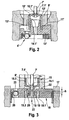
- Fig. 3 It can also be seen that the sealing lip 19 is pressed sealingly against the tubular continuation 16 by means of a corresponding design of a first annular groove 19.1 arranged in the valve element 18 by the pressure difference and / or flow direction of the operating medium, see directional arrows 27.
- the degree of pressure support can be adjusted via a length difference h between the sealing region 20 of the sealing lip 19 on the tubular continuation 16 and a depth of the first annular groove 19.1 arranged in the valve element 18. This means that over the difference in length h, the ratio of a seal-enhancing surface to a sealing-releasing surface of the sealing lip 19 can be adjusted, where h> 0 applies.
- the sealing lip 19 'of the valve member 18' extends extended downwards and has below the tubular continuation 16 a constriction 23, the diameter of which can be set to set a desired throttle effect.
- the rigidity of the valve member 18 ' may, as shown Fig. 4 can be seen, for example, reduced by introducing at least one circumferential, non-solid executed portion, which is exemplified here as a circumferential second annular groove 24, wherein the second annular groove 24 is shown in dashed lines.
- the circumferential second annular groove 24 can be locally stiffened if necessary by radial ribs, not shown.
- the solenoid valve according to the invention enables a robust and uniform design of the valve component, which forms the lower portion of the solenoid valve, whereby the sealing function between the valve body and the Ventilbaubauelement can be ensured with relatively little effort.
- the valve member can be made by the more uniform design by simpler manufacturing processes with simpler tools.
Description
Die Erfindung betrifft ein Magnetventil nach der Gattung des unabhängigen Patentanspruchs 1.The invention relates to a solenoid valve according to the preamble of
Ein herkömmliches Magnetventil, insbesondere für ein Hydraulikaggregat, welches beispielsweise in einem Antiblockiersystem (ABS) oder einem Antriebsschlupfregelsystem (ASR-System) oder einem elektronischen Stabilitätsprogrammsystem (ESP-System) eingesetzt wird, ist in
Zudem nimmt der Ventileinsatz 9 den so genannten Ventilkörper 10 auf, der einen Hauptventilsitz 10.1 umfasst, in welchen das als Stößel ausgeführte erste Schließelement 7 über ein als Dichtkalotte ausgeführtes Hauptdichtelement 7.1 dichtend eintaucht, um die Dichtfunktion des Magnetventils 1 umzusetzen. Wie weiter aus
Das Ventilbauelement 14 wird über einen Dom 13 in eine Innenbohrung 14.1 des Ventilkörpers 10 eingeschoben und dichtet dort druckunterstützt an einer Dichtstelle 12 ab. Der Ventilkörper 10 ist in den Ventileinsatz 9 eingepresst, wobei der Hauptdichtsitz 10.1 oben am Ventilkörper 10 angeordnet ist und der Pressdurchmesser zum Ventileinsatz 9 tiefer liegt. Zudem stützt sich das Ventilbauelement 14 axial auf dem Ventileinsatz 9 mit einer Fläche 11 ab.The
Da bei beiden herkömmlichen Ausführungsbeispielen gemäß
Die Offenlegungsschrift
Die Offenlegungsschrift
Das erfindungsgemäße Magnetventil mit den Merkmalen des unabhängigen Patentanspruchs 1 hat demgegenüber den Vorteil, dass ein als Hülse ausgeführter Ventilkörper mit einem offenen Ende in einen Ventileinsatz eingepresst ist, wobei ein Hauptventilsitz mit einer Durchgangsöffnung innen an einem haubenförmigen Ende der Ventilkörperhülse angeordnet ist. Zudem ist die Ventilkörperhülse am haubenförmigen Ende durch eine rohrförmige Fortsetzung verlängert ausgeführt, so dass die Abdichtung mit einen Ventilbauelement über eine an der rohrförmigen Fortsetzung außen dichtend anliegenden Dichtlippe herstellbar ist. Die neue Formgebung der Abdichtung zwischen dem Ventilbauelement und dem Ventilkörper enmöglicht in vorteilhafter Weise eine robustere Ausführung und eine sichere Dichtfunktion. Die zur Abdichtung und Einsetzung notwendige axiale Überdeckung von Ventilkörper und Ventilbauelement wird durch die Verlängerung des Ventilkörpers erreicht, der vorzugsweise als robustes Metallbauteil, insbesondere als Stahlbauteil ausgeführt ist. Zudem kann das Ventilbauelement gleichförmiger ausgeführt werden. Die höhere Robustheit führt in vorteilhafter Weise zu einem geringeren Absicherungsaufwand, und die gleichförmigere Gestaltung führt insbesondere bei Kunststoffteilen zu einfacheren Herstellprozessen mit einfachen Werkzeugen und erhöht wiederum die Robustheit des Bauteils.The solenoid valve according to the invention with the features of
Durch die in den abhängigen Ansprüchen aufgeführten Maßnahmen und Weiterbildungen sind vorteilhafte Verbesserungen des im unabhängigen Patentanspruch 1 angegebenen Magnetventils möglich.The measures and refinements recited in the dependent claims advantageous improvements of the
Besonders vorteilhaft ist, dass die Dichtlippe mittels einer entsprechenden Gestaltung einer im Ventilbauelement angeordneten ersten Ringnut durch die Druckdifferenz und/oder Strömungsrichtung des Betriebsmediums druckunterstützt dichtend gegen die rohrförmige Fortsetzung gepresst wird. Der Grad der Druckunterstützung kann beispielsweise über einen Längenunterschied zwischen einem Dichtbereich der Dichtlippe an der rohrförmigen Fortsetzung und einer Tiefe einer im Ventilbauelement angeordneten ersten Ringnut eingestellt werden. Über den Längenunterschied kann das Verhältnis einer dichtungsverstärkend wirkenden Fläche zu einer dichtungslösend wirkenden Fläche eingestellt werden.It is particularly advantageous that the sealing lip is pressed by means of a corresponding design of a valve disposed in the first annular element by the pressure difference and / or flow direction of the operating medium pressure-assisted sealingly pressed against the tubular continuation. The degree of pressure support can be set, for example, over a difference in length between a sealing area of the sealing lip on the tubular continuation and a depth of a first annular groove arranged in the valve element. About the difference in length, the ratio of a seal-enhancing surface to a sealing release acting surface can be adjusted.
In Ausgestaltung des erfindungsgemäßen Magnetventils kann die Dichtlippe des Ventilbauelements nach unten verlängert werden und unterhalb der rohrförmigen Fortsetzung eine Verengung aufweisen, deren Durchmesser zur Einstellung einer gewünschten Drosselwirkung vorgegeben werden kann. Dies ermöglicht in vorteilhafter Weise eine einfache Variantenbildung, um das Magnetventil in Abhängigkeit von den Systemerfordernissen mit unterschiedlichen Drosselgrößen realisieren zu können.In an embodiment of the solenoid valve according to the invention, the sealing lip of the valve member can be extended down and below the tubular continuation having a constriction whose diameter can be set to set a desired throttle effect. This advantageously allows a simple variant formation in order to be able to realize the solenoid valve as a function of the system requirements with different throttle variables.
Die Dichtlippe des Ventilbauelements wird durch die Abdichtung auf der Fortsetzung des Ventilkörpers verformt. Damit diese Verformung keinen oder nur einen verminderten Einfluss auf die Rundheit eines exzentrisch angeordneten Rückschlagventilsitzes hat, kann der Rückschlagventilsitz durch geeignete Entkopplungsmittel von der Dichtlippe entkoppelt werden. Die Entkoppelung kann beispielsweise durch eine bewusst herbeigeführte Reduzierung der Steifigkeit des Ventilbauelements umgesetzt werden. Die Steifigkeit des Ventilbauelements kann beispielsweise durch Einführung von mindestens einer umlaufenden zweiten Ringnut reduziert werden. Die mindestens eine umlaufende zweite Ringnut kann durch Radialrippen örtlich versteift werden.The sealing lip of the valve member is deformed by the seal on the continuation of the valve body. So that this deformation has no or only a reduced influence on the roundness of an eccentrically arranged non-return valve seat, the check valve seat can be decoupled from the sealing lip by suitable decoupling means. The decoupling can be implemented, for example, by deliberately reducing the rigidity of the valve component. The rigidity of the valve component can be reduced for example by introducing at least one circumferential second annular groove. The at least one circumferential second annular groove can be locally stiffened by radial ribs.
Vorteilhafte, nachfolgend beschriebene Ausführungsformen der Erfindung sowie die zu deren besserem Verständnis oben erläuterten, herkömmlichen Ausführungsbeispiele sind in den Zeichnungen dargestellt. In den Zeichnungen bezeichnen gleiche Bezugszeichen Komponenten bzw. Elemente, die gleiche bzw. analoge Funktionen ausführen.Advantageous embodiments of the invention described below, as well as those explained above for better understanding thereof, are shown in the drawings. In the drawings, like reference numerals designate components that perform the same or analog functions.
-
Fig. 1 zeigt eine schematische Schnittdarstellung eines herkömmlichen Magnetventils.Fig. 1 shows a schematic sectional view of a conventional solenoid valve. -
Fig. 2 zeigt eine schematische Schnittdarstellung eines unteren Bereichs eines herkömmlichen Magnetventils.Fig. 2 shows a schematic sectional view of a lower portion of a conventional solenoid valve. -
Fig. 3 zeigt eine schematische Schnittdarstellung einer ersten Ausführungsform eines unteren Bereichs eines erfindungsgemäßen Magnetventils.Fig. 3 shows a schematic sectional view of a first embodiment of a lower portion of a solenoid valve according to the invention. -
Fig. 4 zeigt eine schematische Schnittdarstellung einer zweiten Ausführungsform eines unteren Bereichs eines erfindungsgemäßen Magnetventils.Fig. 4 shows a schematic sectional view of a second embodiment of a lower portion of a solenoid valve according to the invention.
Wie aus
Bei den Ausführungsformen gemäß
Wie aus
Im Unterschied zur ersten Ausführungsform gemäß
Bei allen erfindungsgemäßen Ausführungsformen ist auf eine strömungsgünstige Gestaltung des Strömungseinlasses zu achten. Zudem bleibt die Abdichtung des Ventilbauelements 18, 18' zum Fluidblock 17 im Vergleich zum Stand der Technik jeweils unverändert. Während des Magnetventilbetriebs wird die Dichtlippe 19, 19' des Ventilbauelements 18, 18' durch die Abdichtung auf der Fortsetzung 16 der Ventilkörperhülse 15 verformt. Damit diese Verformung keinen oder nur einen minimalen Einfluss auf die Rundheit eines exzentrisch zur Hauptventilachse angeordneten Rückschlagventilsitzes 25, 25' aufweist, der mit einem korrespondierenden Dichtelement 26, 26' zusammenwirkt, kann durch eine bewusst herbeigeführte Verringerung der Steifigkeit des Ventilbauelements 18, 18' eine Entkoppelung umgesetzt werden.In all the embodiments according to the invention, attention must be paid to a streamlined design of the flow inlet. In addition, the sealing of the
Die Steifigkeit des Ventilbauelements 18' kann, wie aus
Das erfindungsgemäße Magnetventil ermöglicht eine robuste und gleichförmige Gestaltung des Ventilbauelements, das den unteren Bereich des Magnetventils bildet, wodurch die Dichtfunktion zwischen dem Ventilkörper und dem Ventilbaubauelement mit einem relativ geringen Aufwand sichergestellt werden kann. Zudem kann das Ventilbauelement durch die gleichförmigere Gestaltung durch einfachere Herstellprozesse mit einfacheren Werkzeugen hergestellt werden.The solenoid valve according to the invention enables a robust and uniform design of the valve component, which forms the lower portion of the solenoid valve, whereby the sealing function between the valve body and the Ventilbaubauelement can be ensured with relatively little effort. In addition, the valve member can be made by the more uniform design by simpler manufacturing processes with simpler tools.
Claims (9)
- Solenoid valve, with a magnetic subassembly (2) and with a valve cartridge (5) which comprises a valve insert (9'), a closing element (7') guided movably within the valve insert (9') and a valve body (15) which is pressed into the valve insert (9'), a main valve having a main sealing element (7.1') connected to the closing element (7') and a main valve seat (15.1) arranged in the valve body (15), a magnetic force generated by the magnetic subassembly moving the closing element (7') in the direction of the valve body (15), with the result that the main sealing element (7.1') penetrates sealingly into the main valve seat (15.1), the valve body (15) being designed as a sleeve, the open end (15.2) of which is pressed into the valve insert (9'), and the main valve seat (15.1) being arranged with a through orifice on the inside at a hood-shaped end (15.3) of the valve body sleeve (15), characterized in that the valve body sleeve (15) is designed to be prolonged at the hood-shaped end (15.3) by a tubular extension (16), so that sealing-off with respect to a valve structural element (18, 18') forming a valve lower part is effected via a sealing lip (19, 19') of the valve structural element (18, 18'), the said sealing lip bearing sealingly on the outside against the tubular extension (16).
- Solenoid valve according to Claim 1, characterized in that the sealing lip (19, 19') is pressed sealingly against the tubular extension (16) by means of a corresponding configuration of a first annular groove (19.1, 19.1') arranged in the valve structural element (18, 18') and with the assistance of pressure caused by the pressure difference and/or the direction of flow of the operating medium.
- Solenoid valve according to Claim 2, characterized in that the degree of pressure assistance can be set via a length difference (h) between a sealing region (20, 20') of the sealing lip (19, 19') on the tubular extension (16) and a depth of the first annular groove (19.1, 19.1') arranged in the valve structural element (18, 18'), the ratio of an area exerting a sealing-reinforcing action to an area exerting a sealing-releasing action being capable of being set via the length difference (h).
- Solenoid valve according to one of Claims 1 to 3, characterized in that the valve body (15) is produced as a metal part, preferably as a steel part, and the valve structural element (18, 18') as a plastic part.
- Solenoid valve according to one of Claims 1 to 4, characterized in that the sealing lip (19') of the valve structural element (18') is prolonged downwards and below the tubular extension (16) has a contraction (23), the diameter of which can be stipulated for the purpose of setting a desired throttle action.
- Solenoid valve according to one of Claims 1 to 5, characterized by a non-return valve seat (25, 25') which is arranged eccentrically in the valve structural element (18, 18') and which is decoupled by suitable decoupling means (24) from the sealing lip (19, 19') which seals on the tubular extension (16).
- Solenoid valve according to Claim 6, characterized in that decoupling is implemented by a deliberately induced reduction in the rigidity of the valve structural element (18').
- Solenoid valve according to Claim 6 or 7, characterized in that the rigidity of the valve structural element (18') is reduced by the introduction of at least one continuous second annular groove (24).
- Solenoid valve according to Claim 8, characterized in that the at least one continuous second annular groove (24) is stiffened locally by means of radial ribs.
Applications Claiming Priority (2)
| Application Number | Priority Date | Filing Date | Title |
|---|---|---|---|
| DE102007028516A DE102007028516A1 (en) | 2007-06-21 | 2007-06-21 | magnetic valve |
| PCT/EP2008/057189 WO2008155256A1 (en) | 2007-06-21 | 2008-06-10 | Solenoid valve |
Publications (2)
| Publication Number | Publication Date |
|---|---|
| EP2170665A1 EP2170665A1 (en) | 2010-04-07 |
| EP2170665B1 true EP2170665B1 (en) | 2012-08-29 |
Family
ID=39711801
Family Applications (1)
| Application Number | Title | Priority Date | Filing Date |
|---|---|---|---|
| EP08760750A Expired - Fee Related EP2170665B1 (en) | 2007-06-21 | 2008-06-10 | Solenoid valve |
Country Status (6)
| Country | Link |
|---|---|
| US (1) | US20100200790A1 (en) |
| EP (1) | EP2170665B1 (en) |
| JP (1) | JP4914521B2 (en) |
| CN (1) | CN101687495B (en) |
| DE (1) | DE102007028516A1 (en) |
| WO (1) | WO2008155256A1 (en) |
Families Citing this family (9)
| Publication number | Priority date | Publication date | Assignee | Title |
|---|---|---|---|---|
| DE102009026853A1 (en) * | 2009-06-09 | 2010-12-16 | Robert Bosch Gmbh | Valve cartridge for a solenoid valve and associated solenoid valve |
| DE102010002284A1 (en) * | 2010-02-24 | 2011-08-25 | Continental Teves AG & Co. OHG, 60488 | Valve arrangement, particularly for slip-controlled motor vehicle braking system, has hydraulically controlled non-return valve in non-return valve housing, where valve closure unit is arranged in tubular housing body |
| DE102010026549A1 (en) * | 2010-07-08 | 2012-01-12 | Magna Steyr Fahrzeugtechnik Ag & Co. Kg | Electromagnetic valve for a pressure vessel |
| DE102010038505A1 (en) * | 2010-07-28 | 2012-02-02 | Continental Teves Ag & Co. Ohg | Valve arrangement for slippage-regular motor car brake assembly, has sleeve portion fixed in pressure medium passage by closing member to open or close pressure medium passage onto sleeve portion that extends from valve seat body |
| DE102010062818A1 (en) * | 2010-12-10 | 2012-06-14 | Continental Teves Ag & Co. Ohg | Valve arrangement, particularly for slip-controlled motor vehicle brake systems, has hydraulically controlled check valve in check valve housing, and electromagnetically controlled valve closing element arranged in tubular housing body |
| DE102011078314A1 (en) * | 2011-06-29 | 2013-01-03 | Robert Bosch Gmbh | magnetic valve |
| DE102012007766A1 (en) * | 2012-04-20 | 2013-10-24 | Bürkert Werke GmbH | Process and manufacture of valves, valves and valve series |
| SE538631C2 (en) * | 2015-04-14 | 2016-10-04 | Staccato Tech Ab | Valve Seat |
| CN110382314B (en) * | 2017-02-17 | 2021-10-01 | 日信工业株式会社 | Electric component assembly and vehicle brake hydraulic pressure control device |
Family Cites Families (22)
| Publication number | Priority date | Publication date | Assignee | Title |
|---|---|---|---|---|
| US831742A (en) * | 1905-06-19 | 1906-09-25 | Henry D Pownall | Valve. |
| NL8403825A (en) * | 1984-12-17 | 1986-07-16 | Nefit Nv | BALL VALVE COMPLETELY MANUFACTURED FROM PLASTIC. |
| ES2032655T5 (en) * | 1988-08-18 | 1996-10-01 | Eaton Sa Monaco | ELECTRICALLY OPERATED FLUID VALVE. |
| DE19531010B4 (en) * | 1995-08-23 | 2004-04-29 | Robert Bosch Gmbh | Solenoid valve, in particular for a slip-controlled, hydraulic brake system for motor vehicles |
| DE19604315A1 (en) * | 1996-02-07 | 1997-08-14 | Bosch Gmbh Robert | Electromagnetically operated valve, in particular for hydraulic brake systems in motor vehicles |
| DE19635693A1 (en) * | 1996-09-03 | 1998-03-05 | Bosch Gmbh Robert | Solenoid valve for a slip-controlled, hydraulic vehicle brake system |
| DE19635691A1 (en) * | 1996-09-03 | 1998-03-05 | Bosch Gmbh Robert | Solenoid valve for a slip-controlled, hydraulic vehicle brake system |
| DE19653832A1 (en) * | 1996-12-21 | 1998-06-25 | Bosch Gmbh Robert | Valve with combined valve seat body and spray orifice plate |
| DE19807130A1 (en) * | 1998-02-20 | 1999-08-26 | Bosch Gmbh Robert | Magnet valve for insertion in accommodation hole of hydraulic block of slip-regulated hydraulic vehicle brake installation |
| DE19843762A1 (en) * | 1998-09-24 | 2000-03-30 | Bosch Gmbh Robert | Solenoid valve, in particular for a slip-controlled, hydraulic vehicle brake system |
| US6364430B1 (en) * | 1998-11-13 | 2002-04-02 | Mando Machinery Corporation | Solenoid valve for anti-lock brake system |
| US6644623B1 (en) * | 1999-06-23 | 2003-11-11 | Continental Teves Ag & Co. Ohg | Electromagnetic valve |
| DE19936711A1 (en) * | 1999-06-23 | 2001-01-11 | Continental Teves Ag & Co Ohg | Solenoid valve, especially for hydraulic brake systems with slip control |
| DE19955886A1 (en) * | 1999-11-20 | 2001-05-23 | Bosch Gmbh Robert | Solenoid valve with a check valve |
| DE10038091B4 (en) * | 2000-08-04 | 2009-01-15 | Robert Bosch Gmbh | Solenoid valve, in particular for a slip-controlled, hydraulic vehicle brake system |
| JP2002347597A (en) * | 2001-05-28 | 2002-12-04 | Bosch Automotive Systems Corp | Solenoid valve and fluid pressure unit for vehicle equipped with the solenoid valve |
| US6530528B2 (en) * | 2001-07-27 | 2003-03-11 | Parker-Hannifin Corporation | Refrigerant expansion valve having electrically operated inlet shutoff with improved armature dampening |
| JP3630304B2 (en) * | 2001-10-15 | 2005-03-16 | 株式会社ボッシュオートモーティブシステム | FUEL LIQUID FLOW RATE CONTROL VALVE AND FUEL INJECTION SYSTEM FOR INTERNAL COMBUSTION ENGINE HAVING THE FUEL LIQUID FLOW RATE CONTROL VALVE |
| EP1636518A2 (en) * | 2002-12-13 | 2006-03-22 | Continental Teves AG & Co. oHG | Electromagnetic valve |
| JP2005132347A (en) * | 2003-10-10 | 2005-05-26 | Advics:Kk | Braking fluid control device |
| JP4487845B2 (en) * | 2005-05-02 | 2010-06-23 | 株式会社デンソー | solenoid valve |
| DE102005044672A1 (en) * | 2005-09-19 | 2007-03-22 | Robert Bosch Gmbh | magnetic valve |
-
2007
- 2007-06-21 DE DE102007028516A patent/DE102007028516A1/en not_active Withdrawn
-
2008
- 2008-06-10 JP JP2010512636A patent/JP4914521B2/en not_active Expired - Fee Related
- 2008-06-10 CN CN200880020543.2A patent/CN101687495B/en not_active Expired - Fee Related
- 2008-06-10 WO PCT/EP2008/057189 patent/WO2008155256A1/en active Application Filing
- 2008-06-10 EP EP08760750A patent/EP2170665B1/en not_active Expired - Fee Related
- 2008-06-10 US US12/665,611 patent/US20100200790A1/en not_active Abandoned
Also Published As
| Publication number | Publication date |
|---|---|
| EP2170665A1 (en) | 2010-04-07 |
| CN101687495B (en) | 2013-02-20 |
| JP4914521B2 (en) | 2012-04-11 |
| DE102007028516A1 (en) | 2008-12-24 |
| JP2010530511A (en) | 2010-09-09 |
| WO2008155256A1 (en) | 2008-12-24 |
| CN101687495A (en) | 2010-03-31 |
| US20100200790A1 (en) | 2010-08-12 |
Similar Documents
| Publication | Publication Date | Title |
|---|---|---|
| EP2170665B1 (en) | Solenoid valve | |
| EP2219913B1 (en) | Valve cartridge for a solenoid valve, and associated solenoid valve | |
| EP2091797B1 (en) | Solenoid valve | |
| EP2219914B1 (en) | Solenoid valve | |
| DE102006003491B4 (en) | magnetic valve | |
| EP2114740B1 (en) | Solenoid valve | |
| DE102007007784B4 (en) | magnetic valve | |
| DE102006054185A1 (en) | magnetic valve | |
| DE102004030428A1 (en) | valve device | |
| DE102006055833A1 (en) | Solenoid valve i.e. currentless open control valve, for e.g. fluid assembly, has closing element, and another closing element implemented as plate in which seat and channel are integrated, where closing directions of elements are opposite | |
| WO2008151904A1 (en) | Solenoid valve | |
| EP2219912A1 (en) | Valve cartridge for a solenoid valve, and associated solenoid valve | |
| WO2008151867A1 (en) | Solenoid valve | |
| DE102015218263A1 (en) | magnetic valve | |
| DE102006052629B4 (en) | magnetic valve | |
| DE102015203733A1 (en) | Valve arrangement and associated valve cartridge and solenoid valve | |
| EP1817216B1 (en) | Electromagnetically actuated valve, in particular in a motor vehicle braking system | |
| DE102019216715A1 (en) | Two-stage solenoid valve | |
| DE102011086313B4 (en) | magnetic valve | |
| WO2018162184A1 (en) | Valve assembly for a solenoid valve, and corresponding solenoid valve | |
| DE102012209729A1 (en) | magnetic valve | |
| EP1911999A1 (en) | Valve body and corresponding magnetic valve | |
| DE102012213761A1 (en) | Valve body for a control valve and corresponding solenoid valve | |
| WO2010142509A1 (en) | Valve cartridge for a magnet valve, and magnet valve comprising such a cartridge | |
| DE102005044674B4 (en) | Solenoid valve, in particular for a hydraulic power unit |
Legal Events
| Date | Code | Title | Description |
|---|---|---|---|
| PUAI | Public reference made under article 153(3) epc to a published international application that has entered the european phase |
Free format text: ORIGINAL CODE: 0009012 |
|
| 17P | Request for examination filed |
Effective date: 20100121 |
|
| AK | Designated contracting states |
Kind code of ref document: A1 Designated state(s): DE ES FR GB |
|
| AX | Request for extension of the european patent |
Extension state: AL BA MK RS |
|
| DAX | Request for extension of the european patent (deleted) | ||
| 17Q | First examination report despatched |
Effective date: 20101126 |
|
| GRAP | Despatch of communication of intention to grant a patent |
Free format text: ORIGINAL CODE: EPIDOSNIGR1 |
|
| GRAS | Grant fee paid |
Free format text: ORIGINAL CODE: EPIDOSNIGR3 |
|
| GRAA | (expected) grant |
Free format text: ORIGINAL CODE: 0009210 |
|
| AK | Designated contracting states |
Kind code of ref document: B1 Designated state(s): DE ES FR GB |
|
| REG | Reference to a national code |
Ref country code: GB Ref legal event code: FG4D Free format text: NOT ENGLISH |
|
| REG | Reference to a national code |
Ref country code: DE Ref legal event code: R096 Ref document number: 502008008064 Country of ref document: DE Effective date: 20121025 |
|
| PG25 | Lapsed in a contracting state [announced via postgrant information from national office to epo] |
Ref country code: ES Free format text: LAPSE BECAUSE OF FAILURE TO SUBMIT A TRANSLATION OF THE DESCRIPTION OR TO PAY THE FEE WITHIN THE PRESCRIBED TIME-LIMIT Effective date: 20121210 |
|
| PLBE | No opposition filed within time limit |
Free format text: ORIGINAL CODE: 0009261 |
|
| STAA | Information on the status of an ep patent application or granted ep patent |
Free format text: STATUS: NO OPPOSITION FILED WITHIN TIME LIMIT |
|
| 26N | No opposition filed |
Effective date: 20130530 |
|
| PGFP | Annual fee paid to national office [announced via postgrant information from national office to epo] |
Ref country code: FR Payment date: 20130703 Year of fee payment: 6 |
|
| REG | Reference to a national code |
Ref country code: DE Ref legal event code: R097 Ref document number: 502008008064 Country of ref document: DE Effective date: 20130530 |
|
| GBPC | Gb: european patent ceased through non-payment of renewal fee |
Effective date: 20130610 |
|
| PG25 | Lapsed in a contracting state [announced via postgrant information from national office to epo] |
Ref country code: GB Free format text: LAPSE BECAUSE OF NON-PAYMENT OF DUE FEES Effective date: 20130610 |
|
| REG | Reference to a national code |
Ref country code: FR Ref legal event code: ST Effective date: 20150227 |
|
| PG25 | Lapsed in a contracting state [announced via postgrant information from national office to epo] |
Ref country code: FR Free format text: LAPSE BECAUSE OF NON-PAYMENT OF DUE FEES Effective date: 20140630 |
|
| REG | Reference to a national code |
Ref country code: DE Ref legal event code: R084 Ref document number: 502008008064 Country of ref document: DE |
|
| PGFP | Annual fee paid to national office [announced via postgrant information from national office to epo] |
Ref country code: DE Payment date: 20220822 Year of fee payment: 15 |
|
| REG | Reference to a national code |
Ref country code: DE Ref legal event code: R119 Ref document number: 502008008064 Country of ref document: DE |