EP2170665B1 - Électrovanne - Google Patents
Électrovanne Download PDFInfo
- Publication number
- EP2170665B1 EP2170665B1 EP08760750A EP08760750A EP2170665B1 EP 2170665 B1 EP2170665 B1 EP 2170665B1 EP 08760750 A EP08760750 A EP 08760750A EP 08760750 A EP08760750 A EP 08760750A EP 2170665 B1 EP2170665 B1 EP 2170665B1
- Authority
- EP
- European Patent Office
- Prior art keywords
- valve
- sealing
- solenoid valve
- valve body
- structural element
- Prior art date
- Legal status (The legal status is an assumption and is not a legal conclusion. Google has not performed a legal analysis and makes no representation as to the accuracy of the status listed.)
- Expired - Fee Related
Links
- 238000007789 sealing Methods 0.000 claims description 60
- 229910000831 Steel Inorganic materials 0.000 claims description 3
- 239000002184 metal Substances 0.000 claims description 3
- 239000010959 steel Substances 0.000 claims description 3
- 230000009467 reduction Effects 0.000 claims description 2
- 230000003578 releasing effect Effects 0.000 claims description 2
- 230000002035 prolonged effect Effects 0.000 claims 2
- 230000008602 contraction Effects 0.000 claims 1
- 238000004804 winding Methods 0.000 description 5
- 239000012530 fluid Substances 0.000 description 4
- 230000004907 flux Effects 0.000 description 3
- 230000015572 biosynthetic process Effects 0.000 description 2
- 239000002775 capsule Substances 0.000 description 2
- 230000000694 effects Effects 0.000 description 2
- 238000004519 manufacturing process Methods 0.000 description 2
- 238000003825 pressing Methods 0.000 description 2
- 230000008901 benefit Effects 0.000 description 1
- 230000001419 dependent effect Effects 0.000 description 1
- 238000009434 installation Methods 0.000 description 1
- 239000007787 solid Substances 0.000 description 1
Images


Classifications
-
- B—PERFORMING OPERATIONS; TRANSPORTING
- B60—VEHICLES IN GENERAL
- B60T—VEHICLE BRAKE CONTROL SYSTEMS OR PARTS THEREOF; BRAKE CONTROL SYSTEMS OR PARTS THEREOF, IN GENERAL; ARRANGEMENT OF BRAKING ELEMENTS ON VEHICLES IN GENERAL; PORTABLE DEVICES FOR PREVENTING UNWANTED MOVEMENT OF VEHICLES; VEHICLE MODIFICATIONS TO FACILITATE COOLING OF BRAKES
- B60T8/00—Arrangements for adjusting wheel-braking force to meet varying vehicular or ground-surface conditions, e.g. limiting or varying distribution of braking force
- B60T8/32—Arrangements for adjusting wheel-braking force to meet varying vehicular or ground-surface conditions, e.g. limiting or varying distribution of braking force responsive to a speed condition, e.g. acceleration or deceleration
- B60T8/34—Arrangements for adjusting wheel-braking force to meet varying vehicular or ground-surface conditions, e.g. limiting or varying distribution of braking force responsive to a speed condition, e.g. acceleration or deceleration having a fluid pressure regulator responsive to a speed condition
- B60T8/36—Arrangements for adjusting wheel-braking force to meet varying vehicular or ground-surface conditions, e.g. limiting or varying distribution of braking force responsive to a speed condition, e.g. acceleration or deceleration having a fluid pressure regulator responsive to a speed condition including a pilot valve responding to an electromagnetic force
- B60T8/3615—Electromagnetic valves specially adapted for anti-lock brake and traction control systems
- B60T8/363—Electromagnetic valves specially adapted for anti-lock brake and traction control systems in hydraulic systems
-
- F—MECHANICAL ENGINEERING; LIGHTING; HEATING; WEAPONS; BLASTING
- F16—ENGINEERING ELEMENTS AND UNITS; GENERAL MEASURES FOR PRODUCING AND MAINTAINING EFFECTIVE FUNCTIONING OF MACHINES OR INSTALLATIONS; THERMAL INSULATION IN GENERAL
- F16K—VALVES; TAPS; COCKS; ACTUATING-FLOATS; DEVICES FOR VENTING OR AERATING
- F16K31/00—Actuating devices; Operating means; Releasing devices
- F16K31/02—Actuating devices; Operating means; Releasing devices electric; magnetic
- F16K31/06—Actuating devices; Operating means; Releasing devices electric; magnetic using a magnet, e.g. diaphragm valves, cutting off by means of a liquid
- F16K31/0644—One-way valve
- F16K31/0655—Lift valves
Definitions
- the invention relates to a solenoid valve according to the preamble of independent claim 1.
- a conventional solenoid valve, in particular for a hydraulic unit, which is used for example in an anti-lock braking system (ABS) or a traction control system (ASR system) or an electronic stability program system (ESP system) is in FIG. 1 shown.
- the conventional solenoid valve 1 which is designed for example as a normally open control valve, a magnetic assembly 2 for generating a magnetic flux comprising a housing shell 2.1, a winding support 2.2, a coil winding 2.3 and a cover 2.4, and a valve cartridge 5, the a capsule 5.1, a connected to the capsule via a sealing seal valve insert 9, an armature 6 with a designed as a ram first closing element 7 and a return spring 8 includes.
- the magnet assembly 2 generates a magnetic force which moves the longitudinally movable armature 6 against the force of the return spring 8 against the valve core 9 with the first closing element 7 designed as a plunger.
- the wound on the winding support 2.2 coil winding 2.3 forms an electrical coil, which is controlled via electrical connections 2.5.
- the armature 6 is counter to the force of the return spring eighth moved against the valve core 9.
- valve core 9 accommodates the so-called valve body 10, which comprises a main valve seat 10.1, in which the first closing element 7 designed as a plunger sealingly dips over a main sealing element 7.1 designed as a sealing dome in order to implement the sealing function of the solenoid valve 1.
- the conventional solenoid valve 1 comprises an eccentrically arranged check valve 4, which performs a directional flow function.
- the check valve 4 of the conventional solenoid valve 1 comprises a movable sealing element, arranged in a valve member 14 check valve seat and a Hubbegrenzungung or plant, which is here formed by a flat filter to limit the maximum stroke of the movable sealing element.
- the eccentrically positioned to the valve main axis check valve 4 has a ball-hollow cone shape in the rule.
- the designed as a plastic insert valve member 14 forms the valve body and is used in addition to sealing to a surrounding fluid block, for sealing the valve body 10 and for receiving a ring filter and the flat filter.
- valve member 14 is inserted via a dome 13 in an inner bore 14.1 of the valve body 10 and seals there pressure-supported at a sealing point 12 from.
- the valve body 10 is pressed into the valve insert 9, wherein the main sealing seat 10.1 is arranged at the top of the valve body 10 and the pressing diameter to the valve insert 9 is lower.
- the valve member 14 is supported axially on the valve core 9 with a surface 11 from.
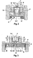
- Fig. 2 shows an alternative embodiment in which the valve body 10 'is designed as a sleeve and in the valve insert 9' is pressed.
- the valve body 10 ' comprises a main valve seat 10.1', in which the first closing element 7 'designed as a plunger sealingly dips over a main sealing element 7.1' designed as a sealing dome in order to implement the sealing function of the solenoid valve 1.
- the illustrated designed as a plastic insert valve component 14 ' comprises an eccentrically arranged check valve 4', which performs a directional flow function.
- the valve component 14 ' forms the valve body and serves in addition to the seal to a surrounding fluid block, for sealing the valve body 10' and for receiving a ring filter and a flat filter.
- the valve component 14 ' is also inserted via a dome 13' in an inner bore 14.1 'of the valve body 10' and seals there pressure-supported at a sealing point 12 'from.
- the valve body 10 ' is pressed into the valve insert 9', the main sealing seat 10.1 'is arranged at the top of the valve body 10' and the pressing diameter to the valve core 9 'is lower.
- the valve member 14 ' is axially supported on the valve core 9' with a surface 11 'from.
- the dome 13, 13 'of the valve member 14, 14' protrudes into the valve body bore 14.1, 14.1 'for sealing, the dome 13, 13' as a relatively thin part on the rather massive volume of the valve assembly 14, 14 'addition.
- the dome 13, 13 ' quite delicate by the very small dimensions and thus designed little robust in terms of strength. This is problematic in the sealing in the valve body 10, 10 'at the positions 12 and 12', and the sealing function must be ensured with relatively great effort.
- the publication JP 2005 132347 A discloses, for example, a solenoid valve having a magnet assembly and a valve cartridge including a valve core, a closure member movably guided within the valve core, and a valve body which is press-fitted into the valve core.
- a main valve has a main seal member connected to the closing member and a valve body arranged in the main valve seat, wherein a magnetic force generated by the magnetic assembly moves the closing element in the direction of the valve body, whereby the main sealing member is sealingly immersed in the main valve seat.
- the valve body is designed as a sleeve, the open end of which is pressed into the valve core, wherein the main valve seat is arranged with a through hole inside a hood-shaped end of the valve body sleeve.
- the publication WO 99/42348 A1 discloses a solenoid valve for a slip-controlled hydraulic vehicle brake system.
- the disclosed solenoid valve includes a seal on a valve seat continuation with sealing lips, wherein the valve continuation is not disposed on a valve body sleeve.
- the solenoid valve according to the invention with the features of independent claim 1 has the advantage that a sleeve designed as a valve body is pressed with an open end in a valve core, wherein a main valve seat with a through hole inside a hood-shaped end of the valve body sleeve is arranged.
- the valve body sleeve is designed extended at the hood-shaped end by a tubular continuation, so that the seal can be produced with a valve member via a sealing lip on the outside of the tubular continuation sealing.
- the new design of the seal between the valve member and the valve body enurbant advantageously a more robust design and a secure sealing function.
- valve body which is preferably designed as a robust metal component, in particular as a steel component.
- valve member can be made uniform. The higher robustness leads advantageously to a lower hedging effort, and the more uniform design leads in particular in plastic parts to simpler manufacturing processes with simple tools and in turn increases the robustness of the component.
- the sealing lip is pressed by means of a corresponding design of a valve disposed in the first annular element by the pressure difference and / or flow direction of the operating medium pressure-assisted sealingly pressed against the tubular continuation.
- the degree of pressure support can be set, for example, over a difference in length between a sealing area of the sealing lip on the tubular continuation and a depth of a first annular groove arranged in the valve element. About the difference in length, the ratio of a seal-enhancing surface to a sealing release acting surface can be adjusted.
- the sealing lip of the valve member can be extended down and below the tubular continuation having a constriction whose diameter can be set to set a desired throttle effect.
- the sealing lip of the valve member is deformed by the seal on the continuation of the valve body. So that this deformation has no or only a reduced influence on the roundness of an eccentrically arranged non-return valve seat, the check valve seat can be decoupled from the sealing lip by suitable decoupling means.
- the decoupling can be implemented, for example, by deliberately reducing the rigidity of the valve component.
- the rigidity of the valve component can be reduced for example by introducing at least one circumferential second annular groove.
- the at least one circumferential second annular groove can be locally stiffened by radial ribs.
- valve body 15 is designed as a sleeve, which in contrast to the prior art according to Fig. 2 is inverted in a valve insert 9 ', ie an upper end 15.2 of the valve body sleeve 15 arranged in the drawing is pressed into the valve insert 9', wherein a main valve seat 15.1 with a passage opening is arranged inside on a hood-shaped end 15.3 of the valve body sleeve 15 , which is arranged in the drawing below.
- valve body sleeve 15 is extended at the hood-shaped end 15.3 extended by a tubular extension 16, so that a required axial overlap for sealing between the valve body sleeve 15 and a valve member 18, 18 'is produced, which forms the valve body.
- a sealing lip 19, 19 'of the valve component 18, 18' bears against the tubular continuation 16 of the valve body sleeve 15 at a sealing region 20, 20 'on the outside in a sealing manner.
- the valve member 18, 18 ' is supported axially on the valve insert 9' with a surface 22, 22 'from.
- the valve body sleeve 15 is designed with the tubular continuation as a metal part, preferably as a steel part, and the valve member 18, 18 'is designed as a plastic part.
- the closing element 7 ' is in each case moved by a magnetic force generated by a magnetic assembly, not shown, in the direction of the valve body 15, whereby the main sealing element 7.1' sealingly in the main valve seat 15.1 is immersed, so that a main fluid flow, which presses from below against the running, for example, as a sealing dome main sealing element 7.1 ', can be adjusted.
- a design as a normally open solenoid valve holds a return spring, the main valve seat 15.1 open in the de-energized state.
- the magnetic assembly not shown, which generates the magnetic force and the magnetic flux in order to move the closing element 7 'when energized against the valve body 15, and the upper portion of the solenoid valve according to the invention can analogously to the in Fig. 1 shown solenoid valve 1 executed with the magnet assembly 2 are.
- Fig. 3 It can also be seen that the sealing lip 19 is pressed sealingly against the tubular continuation 16 by means of a corresponding design of a first annular groove 19.1 arranged in the valve element 18 by the pressure difference and / or flow direction of the operating medium, see directional arrows 27.
- the degree of pressure support can be adjusted via a length difference h between the sealing region 20 of the sealing lip 19 on the tubular continuation 16 and a depth of the first annular groove 19.1 arranged in the valve element 18. This means that over the difference in length h, the ratio of a seal-enhancing surface to a sealing-releasing surface of the sealing lip 19 can be adjusted, where h> 0 applies.
- the sealing lip 19 'of the valve member 18' extends extended downwards and has below the tubular continuation 16 a constriction 23, the diameter of which can be set to set a desired throttle effect.
- the rigidity of the valve member 18 ' may, as shown Fig. 4 can be seen, for example, reduced by introducing at least one circumferential, non-solid executed portion, which is exemplified here as a circumferential second annular groove 24, wherein the second annular groove 24 is shown in dashed lines.
- the circumferential second annular groove 24 can be locally stiffened if necessary by radial ribs, not shown.
- the solenoid valve according to the invention enables a robust and uniform design of the valve component, which forms the lower portion of the solenoid valve, whereby the sealing function between the valve body and the Ventilbaubauelement can be ensured with relatively little effort.
- the valve member can be made by the more uniform design by simpler manufacturing processes with simpler tools.
Claims (9)
- Électrovanne comprenant un module magnétique (2) et une cartouche d'électrovanne (5) qui comprend un insert d'électrovanne (9'), un élément de fermeture (7') guidé de manière mobile à l'intérieur de l'insert d'électrovanne (9') et un corps de soupape (15) qui est enfoncé dans l'insert d'électrovanne (9'), une soupape principale comprenant un élément d'étanchéité principal (7.1') relié à l'élément de fermeture (7') et un siège de soupape principale (15.1) disposé dans le corps de soupape (15), une force magnétique produite par le module magnétique déplaçant l'élément de fermeture (7') en direction du corps de soupape (15), de sorte que l'élément d'étanchéité principal (7.1') plonge hermétiquement dans le siège de soupape principale (15.1), le corps de soupape (15) étant réalisé sous forme de douille dont l'extrémité ouverte (15.2) est enfoncée dans l'insert d'électrovanne (9'), et le siège de soupape principale (15.1) doté d'une ouverture traversante étant disposé à l'intérieur à une extrémité (15.3) en forme de coiffe de la douille de corps de soupape (15), caractérisée en ce que la douille de corps de soupape (15) est réalisée de manière prolongée à l'extrémité (15.3) en forme de coiffe par une extension tubulaire (16), de manière à réaliser l'étanchéité par rapport à un élément structural d'électrovanne (18, 18'), qui forme une partie inférieure d'électrovanne, par l'intermédiaire d'une lèvre d'étanchéité (19, 19') de l'élément structural d'électrovanne (18, 18') s'appliquant hermétiquement à l'extérieur contre l'extension tubulaire (16).
- Électrovanne selon la revendication 1, caractérisée en ce que la lèvre d'étanchéité (19, 19'), grâce à une configuration correspondante d'une première rainure annulaire (19.1, 19.1') disposée dans l'élément structural d'électrovanne (18, 18'), est pressée hermétiquement contre l'extension tubulaire (16) de manière assistée par la pression grâce à la différence de pression et/ou la direction d'écoulement du fluide de travail.
- Électrovanne selon la revendication 2, caractérisée en ce que le degré de l'assistance par pression peut être réglé au moyen d'une différence de longueur (h) entre une région d'étanchéité (20, 20') de la lèvre d'étanchéité (19, 19') contre l'extension tubulaire (16) et une profondeur de la première rainure annulaire (19.1, 19.1') disposée dans l'élément structural d'électrovanne (18, 18'), le rapport d'une surface agissant de manière à renforcer l'étanchéité à une surface agissant de manière à supprimer l'étanchéité pouvant être réglé au moyen de la différence de longueur (h).
- Électrovanne selon l'une quelconque des revendications 1 à 3, caractérisée en ce que le corps de soupape (15) est réalisé sous forme de pièce métallique, de préférence sous forme de pièce en acier, et l'élément structural d'électrovanne (18, 18') est réalisé sous forme de pièce en plastique.
- Électrovanne selon l'une quelconque des revendications 1 à 4, caractérisée en ce que la lèvre d'étanchéité (19') de l'élément structural d'électrovanne (18') est prolongée vers le bas et comporte, en dessous de l'extension tubulaire (16), un étranglement (23) dont le diamètre peut être prédéfini en vue du réglage d'un effet d'étranglement souhaité.
- Électrovanne selon l'une quelconque des revendications 1 à 5, caractérisée par un siège de soupape anti-retour (25, 25') qui est disposé de manière excentrée dans l'élément structural d'électrovanne (18, 18') et qui est désaccouplé, par des moyens de désaccouplage (24) appropriés, de la lèvre d'étanchéité (19, 19') assurant l'étanchéité sur l'extension tubulaire (16).
- Électrovanne selon la revendication 6, caractérisée en ce que le désaccouplage est réalisé par une réduction, provoquée intentionnellement, de la rigidité de l'élément structural d'électrovanne (18').
- Électrovanne selon la revendication 6 ou 7, caractérisée en ce que la rigidité de l'élément structural d'électrovanne (18') est réduite par l'introduction d'au moins une deuxième rainure annulaire périphérique (24).
- Électrovanne selon la revendication 8, caractérisée en ce que l'au moins une deuxième rainure annulaire périphérique (24) est rigidifiée localement par des nervures radiales.
Applications Claiming Priority (2)
| Application Number | Priority Date | Filing Date | Title |
|---|---|---|---|
| DE102007028516A DE102007028516A1 (de) | 2007-06-21 | 2007-06-21 | Magnetventil |
| PCT/EP2008/057189 WO2008155256A1 (fr) | 2007-06-21 | 2008-06-10 | Électrovalve |
Publications (2)
| Publication Number | Publication Date |
|---|---|
| EP2170665A1 EP2170665A1 (fr) | 2010-04-07 |
| EP2170665B1 true EP2170665B1 (fr) | 2012-08-29 |
Family
ID=39711801
Family Applications (1)
| Application Number | Title | Priority Date | Filing Date |
|---|---|---|---|
| EP08760750A Expired - Fee Related EP2170665B1 (fr) | 2007-06-21 | 2008-06-10 | Électrovanne |
Country Status (6)
| Country | Link |
|---|---|
| US (1) | US20100200790A1 (fr) |
| EP (1) | EP2170665B1 (fr) |
| JP (1) | JP4914521B2 (fr) |
| CN (1) | CN101687495B (fr) |
| DE (1) | DE102007028516A1 (fr) |
| WO (1) | WO2008155256A1 (fr) |
Families Citing this family (9)
| Publication number | Priority date | Publication date | Assignee | Title |
|---|---|---|---|---|
| DE102009026853A1 (de) * | 2009-06-09 | 2010-12-16 | Robert Bosch Gmbh | Ventilpatrone für ein Magnetventil und zugehöriges Magnetventil |
| DE102010002284A1 (de) * | 2010-02-24 | 2011-08-25 | Continental Teves AG & Co. OHG, 60488 | Ventilanordnung, insbesondere für schlupfgeregelte Kraftfahrzeug-Bremsanlagen |
| DE102010026549A1 (de) * | 2010-07-08 | 2012-01-12 | Magna Steyr Fahrzeugtechnik Ag & Co. Kg | Elektromagnetisches Ventil für einen Druckbehälter |
| DE102010038505A1 (de) * | 2010-07-28 | 2012-02-02 | Continental Teves Ag & Co. Ohg | Ventilanordnung, insbesondere für schlupfgeregelte Kraftfahrzeug-Bremsanlagen |
| DE102010062818A1 (de) * | 2010-12-10 | 2012-06-14 | Continental Teves Ag & Co. Ohg | Ventilanordnung, insbesondere für schlupfgeregelte Kraftfahrzeug-Bremsanlagen |
| DE102011078314A1 (de) * | 2011-06-29 | 2013-01-03 | Robert Bosch Gmbh | Magnetventil |
| DE102012007766A1 (de) * | 2012-04-20 | 2013-10-24 | Bürkert Werke GmbH | Verfahren und Herstellung von Ventilen, Ventile sowie Ventilserie |
| SE538631C2 (sv) * | 2015-04-14 | 2016-10-04 | Staccato Tech Ab | Valve Seat |
| WO2018151266A1 (fr) * | 2017-02-17 | 2018-08-23 | 日信工業株式会社 | Ensemble de composants électriques et dispositif de commande de pression de liquide de frein pour véhicule |
Family Cites Families (22)
| Publication number | Priority date | Publication date | Assignee | Title |
|---|---|---|---|---|
| US831742A (en) * | 1905-06-19 | 1906-09-25 | Henry D Pownall | Valve. |
| NL8403825A (nl) * | 1984-12-17 | 1986-07-16 | Nefit Nv | Kogelafsluiter die geheel is vervaardigd uit kunststof. |
| DE68901829T4 (de) * | 1988-08-18 | 1997-02-13 | Eaton Sa Monaco | Elektrisch betätigtes Fluidventil. |
| DE19531010B4 (de) * | 1995-08-23 | 2004-04-29 | Robert Bosch Gmbh | Magnetventil, insbesondere für eine schlupfgeregelte, hydraulische Bremsanlage für Kraftfahrzeuge |
| DE19604315A1 (de) * | 1996-02-07 | 1997-08-14 | Bosch Gmbh Robert | Elektromagnetisch betätigtes Ventil, insbesondere für hydraulische Bremsanlagen von Kraftfahrzeugen |
| DE19635691A1 (de) * | 1996-09-03 | 1998-03-05 | Bosch Gmbh Robert | Magnetventil für eine schlupfgeregelte, hydraulische Fahrzeugbremsanlage |
| DE19635693A1 (de) * | 1996-09-03 | 1998-03-05 | Bosch Gmbh Robert | Magnetventil für eine schlupfgeregelte, hydraulische Fahrzeugbremsanlage |
| DE19653832A1 (de) * | 1996-12-21 | 1998-06-25 | Bosch Gmbh Robert | Ventil mit kombiniertem Ventilsitzkörper und Spritzlochscheibe |
| DE19807130A1 (de) * | 1998-02-20 | 1999-08-26 | Bosch Gmbh Robert | Magnetventil für eine schlupfgeregelte, hydraulische Fahrzeugbremsanlage |
| DE19843762A1 (de) * | 1998-09-24 | 2000-03-30 | Bosch Gmbh Robert | Magnetventil, insbesondere für eine schlupfgeregelte, hydraulische Fahrzeugbremsanlage |
| US6364430B1 (en) * | 1998-11-13 | 2002-04-02 | Mando Machinery Corporation | Solenoid valve for anti-lock brake system |
| DE19936711A1 (de) * | 1999-06-23 | 2001-01-11 | Continental Teves Ag & Co Ohg | Elektromagnetventil, insbesondere für hyraulische Bremsanlagen mit Schlupfregelung |
| EP1194322B1 (fr) * | 1999-06-23 | 2005-06-08 | Continental Teves AG & Co. oHG | Soupape electromagnetique, notamment pour systemes de freinage hydrauliques a antiblocage |
| DE19955886A1 (de) * | 1999-11-20 | 2001-05-23 | Bosch Gmbh Robert | Magnetventil mit einem Rückschlagventil |
| DE10038091B4 (de) * | 2000-08-04 | 2009-01-15 | Robert Bosch Gmbh | Magnetventil, insbesondere für eine schlupfgeregelte, hydraulische Fahrzeugbremsanlage |
| JP2002347597A (ja) * | 2001-05-28 | 2002-12-04 | Bosch Automotive Systems Corp | 電磁弁、及び該電磁弁を備えた車両用液圧ユニット |
| US6530528B2 (en) * | 2001-07-27 | 2003-03-11 | Parker-Hannifin Corporation | Refrigerant expansion valve having electrically operated inlet shutoff with improved armature dampening |
| JP3630304B2 (ja) * | 2001-10-15 | 2005-03-16 | 株式会社ボッシュオートモーティブシステム | 燃料液流量調節弁、及び該燃料液流量調節弁を備えた内燃機関の燃料噴射システム |
| JP2006516703A (ja) * | 2002-12-13 | 2006-07-06 | コンチネンタル・テベス・アーゲー・ウント・コンパニー・オーハーゲー | 電磁弁 |
| JP2005132347A (ja) | 2003-10-10 | 2005-05-26 | Advics:Kk | ブレーキ用流体制御装置 |
| JP4487845B2 (ja) * | 2005-05-02 | 2010-06-23 | 株式会社デンソー | 電磁弁 |
| DE102005044672A1 (de) * | 2005-09-19 | 2007-03-22 | Robert Bosch Gmbh | Magnetventil |
-
2007
- 2007-06-21 DE DE102007028516A patent/DE102007028516A1/de not_active Withdrawn
-
2008
- 2008-06-10 CN CN200880020543.2A patent/CN101687495B/zh not_active Expired - Fee Related
- 2008-06-10 US US12/665,611 patent/US20100200790A1/en not_active Abandoned
- 2008-06-10 JP JP2010512636A patent/JP4914521B2/ja not_active Expired - Fee Related
- 2008-06-10 EP EP08760750A patent/EP2170665B1/fr not_active Expired - Fee Related
- 2008-06-10 WO PCT/EP2008/057189 patent/WO2008155256A1/fr active Application Filing
Also Published As
| Publication number | Publication date |
|---|---|
| US20100200790A1 (en) | 2010-08-12 |
| JP2010530511A (ja) | 2010-09-09 |
| CN101687495B (zh) | 2013-02-20 |
| WO2008155256A1 (fr) | 2008-12-24 |
| DE102007028516A1 (de) | 2008-12-24 |
| JP4914521B2 (ja) | 2012-04-11 |
| EP2170665A1 (fr) | 2010-04-07 |
| CN101687495A (zh) | 2010-03-31 |
Similar Documents
| Publication | Publication Date | Title |
|---|---|---|
| EP2170665B1 (fr) | Électrovanne | |
| EP2219913B1 (fr) | Cartouche pour électrovanne et électrovanne correspondante | |
| EP2091797B1 (fr) | Électrovanne | |
| EP2219914B1 (fr) | Électrovanne | |
| DE102006003491B4 (de) | Magnetventil | |
| EP2114740B1 (fr) | Soupape magnétique | |
| DE102007007784B4 (de) | Magnetventil | |
| DE102006054185A1 (de) | Magnetventil | |
| DE102004030428A1 (de) | Ventilvorrichtung | |
| DE102006055833A1 (de) | Magnetventil | |
| WO2008151904A1 (fr) | Électrovanne | |
| EP2219912A1 (fr) | Cartouche pour une électrovanne et électrovanne correspondante | |
| WO2008151867A1 (fr) | Électrovanne | |
| DE102015218263A1 (de) | Magnetventil | |
| DE102006052629B4 (de) | Magnetventil | |
| DE102015203733A1 (de) | Ventilanordnung und zugehörige Ventilpatrone sowie Magnetventil | |
| EP1817216B1 (fr) | Soupape a actionnement electromagnetique, en particulier dans un systeme de freinage d'un vehicule a moteur | |
| DE102019216715A1 (de) | Zweistufiges Magnetventil | |
| DE102011086313B4 (de) | Magnetventil | |
| WO2018162184A1 (fr) | Ensemble vanne pour une électrovanne et électrovanne correspondante | |
| DE102012209729A1 (de) | Magnetventil | |
| EP1911999A1 (fr) | Corps de soupape et soupape magnétique correspondante | |
| DE102012213761A1 (de) | Ventilkörper für ein Stellventil und korrespondierendes Magnetventil | |
| WO2010142509A1 (fr) | Cartouche pour électrovanne et électrovanne dotée d'une telle cartouche | |
| DE102004030424A1 (de) | Ventilvorrichtung |
Legal Events
| Date | Code | Title | Description |
|---|---|---|---|
| PUAI | Public reference made under article 153(3) epc to a published international application that has entered the european phase |
Free format text: ORIGINAL CODE: 0009012 |
|
| 17P | Request for examination filed |
Effective date: 20100121 |
|
| AK | Designated contracting states |
Kind code of ref document: A1 Designated state(s): DE ES FR GB |
|
| AX | Request for extension of the european patent |
Extension state: AL BA MK RS |
|
| DAX | Request for extension of the european patent (deleted) | ||
| 17Q | First examination report despatched |
Effective date: 20101126 |
|
| GRAP | Despatch of communication of intention to grant a patent |
Free format text: ORIGINAL CODE: EPIDOSNIGR1 |
|
| GRAS | Grant fee paid |
Free format text: ORIGINAL CODE: EPIDOSNIGR3 |
|
| GRAA | (expected) grant |
Free format text: ORIGINAL CODE: 0009210 |
|
| AK | Designated contracting states |
Kind code of ref document: B1 Designated state(s): DE ES FR GB |
|
| REG | Reference to a national code |
Ref country code: GB Ref legal event code: FG4D Free format text: NOT ENGLISH |
|
| REG | Reference to a national code |
Ref country code: DE Ref legal event code: R096 Ref document number: 502008008064 Country of ref document: DE Effective date: 20121025 |
|
| PG25 | Lapsed in a contracting state [announced via postgrant information from national office to epo] |
Ref country code: ES Free format text: LAPSE BECAUSE OF FAILURE TO SUBMIT A TRANSLATION OF THE DESCRIPTION OR TO PAY THE FEE WITHIN THE PRESCRIBED TIME-LIMIT Effective date: 20121210 |
|
| PLBE | No opposition filed within time limit |
Free format text: ORIGINAL CODE: 0009261 |
|
| STAA | Information on the status of an ep patent application or granted ep patent |
Free format text: STATUS: NO OPPOSITION FILED WITHIN TIME LIMIT |
|
| 26N | No opposition filed |
Effective date: 20130530 |
|
| PGFP | Annual fee paid to national office [announced via postgrant information from national office to epo] |
Ref country code: FR Payment date: 20130703 Year of fee payment: 6 |
|
| REG | Reference to a national code |
Ref country code: DE Ref legal event code: R097 Ref document number: 502008008064 Country of ref document: DE Effective date: 20130530 |
|
| GBPC | Gb: european patent ceased through non-payment of renewal fee |
Effective date: 20130610 |
|
| PG25 | Lapsed in a contracting state [announced via postgrant information from national office to epo] |
Ref country code: GB Free format text: LAPSE BECAUSE OF NON-PAYMENT OF DUE FEES Effective date: 20130610 |
|
| REG | Reference to a national code |
Ref country code: FR Ref legal event code: ST Effective date: 20150227 |
|
| PG25 | Lapsed in a contracting state [announced via postgrant information from national office to epo] |
Ref country code: FR Free format text: LAPSE BECAUSE OF NON-PAYMENT OF DUE FEES Effective date: 20140630 |
|
| REG | Reference to a national code |
Ref country code: DE Ref legal event code: R084 Ref document number: 502008008064 Country of ref document: DE |
|
| PGFP | Annual fee paid to national office [announced via postgrant information from national office to epo] |
Ref country code: DE Payment date: 20220822 Year of fee payment: 15 |
|
| REG | Reference to a national code |
Ref country code: DE Ref legal event code: R119 Ref document number: 502008008064 Country of ref document: DE |