EP1810268B1 - Werbevitrine - Google Patents
Werbevitrine Download PDFInfo
- Publication number
- EP1810268B1 EP1810268B1 EP05803312A EP05803312A EP1810268B1 EP 1810268 B1 EP1810268 B1 EP 1810268B1 EP 05803312 A EP05803312 A EP 05803312A EP 05803312 A EP05803312 A EP 05803312A EP 1810268 B1 EP1810268 B1 EP 1810268B1
- Authority
- EP
- European Patent Office
- Prior art keywords
- frame
- display case
- advertising display
- case according
- light
- Prior art date
- Legal status (The legal status is an assumption and is not a legal conclusion. Google has not performed a legal analysis and makes no representation as to the accuracy of the status listed.)
- Not-in-force
Links
Images


Classifications
-
- G—PHYSICS
- G09—EDUCATION; CRYPTOGRAPHY; DISPLAY; ADVERTISING; SEALS
- G09F—DISPLAYING; ADVERTISING; SIGNS; LABELS OR NAME-PLATES; SEALS
- G09F13/00—Illuminated signs; Luminous advertising
- G09F13/04—Signs, boards or panels, illuminated from behind the insignia
- G09F13/14—Arrangements of reflectors therein
Definitions
- the invention relates to a display case with a frame-like housing, at least one formed on a translucent support advertising space and at least one light source disposed inside the housing, and by means of the advertising space on its back is illuminated, wherein in the interior of the housing substantially strip-shaped Reflectors are arranged with which the light emanating from the light source can be directed to the back of the advertising space.
- Such a display case is used in particular on public streets and squares use and makes it possible to install on one or more billboards advertising billboard or other visual advertising element in an exchangeable manner.
- a display case of the type mentioned is usually lit by the backlit advertising space, i. inside the housing, a plurality of light sources are arranged, with which the advertising space and thus the advertising billboard located thereon can be illuminated from the back.
- the light source in the middle of the housing, as for example in the DE-A-30 33 462 is shown.
- the light source In order to avoid excessive illumination of the center of the billboard, the light source must be provided with covers that act as auxiliary optics. This auxiliary optics must be mounted and aligned exactly, whereby the assembly is expensive.
- the substrate or the advertising surface has a diffuse, e.g. a diffuser is assigned, the brightness differences occurring on the billboard can indeed reduce some, but remain particularly at the edge of the billboard still poorly lit areas.
- the invention has for its object to procure a display case of the type mentioned, in the simple and cost-effective manner a uniformly illuminated advertising space can be achieved.
- the arranged inside the housing reflectors form a circumferential, preferably closed frame which limits at least one frame field, wherein the light source or the light sources are arranged in the interior of the frame field.
- the frame is substantially planar and lies in the plane of the frame-like housing.
- the frame formed from the reflectors may be formed in its dimensions to the dimensions of the housing, that it is arranged on or near the inner wall of the housing.
- the reflectors forming the frame have convex reflector surfaces on their side facing the center of the frame field. In this way, it is ensured that the light reflected at the reflectors preferably illuminates the edge regions of the advertising surface, thereby avoiding the formation of darkened zones in these edge regions.
- the absorption losses occurring inside the housing can be substantially reduced, so that with a relatively small number of light sources a uniform light distribution on the advertising space is ensured with relatively low energy consumption.
- the reflectors the light can be distributed within the display case in a suitable manner on the advertising surfaces, wherein the carrier or the advertising surface is preferably associated with a scattering disc in the case of the advertising display case according to the invention.
- the mounting of the frame formed by the reflectors is facilitated if the frame is formed in a further development of the invention as a prefabricated, intrinsically stable assembly, which only has to be used and fixed in the housing of the advertising display case.
- the strip-shaped reflectors forming the frame preferably have, at least on their side facing the center of the frame field or the light source, a continuously curved, convex cross-section which may be substantially semicircular in shape, with convex reflector surface facing the center of the frame field.
- the strip-shaped reflectors may have a polygon cross-section and in particular a substantially triangular cross-section, the base of the triangular shape facing the outer housing and the apex of the triangular shape facing the center of the frame. In this way, reflector surfaces extending obliquely to the center plane of the frame and thus of the advertising display case are formed, which deflect the light effectively onto the advertising surfaces.
- the reflective surfaces of the strip-shaped reflectors may direct the light either directionally or non-directionally, i. diffusely reflected.
- the outer circumferential frame is subdivided in a further development of the invention by rod-shaped reflector webs into a plurality of frame fields, wherein in each frame field at least one light source is arranged.
- the frame fields are preferably the same size and each receive a tubular light source, in particular a fluorescent tube, wherein the tubular light sources are parallel to each other. In this way, each light source is surrounded by its own sub-frame, so that by the respective light source emitted light can be effectively reflected and deflected in the desired direction.
- the rod-shaped reflector webs have, for example, a substantially diamond-shaped or rectangular cross-section, wherein in each case one corner of the diamond or rectangular shape faces the associated light source.
- the rod-shaped reflectors may have a circular or elliptical, convex cross-section. In an elliptical cross-sectional shape of the reflector webs, this should be aligned so that the longer major axis of the ellipse lies substantially in the frame plane and facing the associated light source.
- the light source or the fluorescent tube is surrounded by a distance from a light control sleeve.
- the light control sleeve has distributed over its circumference areas of different light transmission.
- the light control sleeve is arranged so that the light emanating from the light source and directed directly to the carrier or to the advertising light light is attenuated by the light control sleeve.
- most of the light emitted by the light source initially runs substantially in or near the center plane of the frame and is then directed onto the carrier or the advertising surface via the reflectors. Only a part of the light emitted by the light source is directed as a result of the light control sleeve directly to the carrier or the advertising space. In this way, an approximately uniform light distribution on the advertising space can be achieved.
- Fig. 1 has a display case 10, an outer frame-like housing 11, in which a reflector frame 12 is inserted, as in Fig. 2 is shown.
- the reflector frame 12 has two parallel spaced, vertical, strip-shaped reflectors 13 and 14, which are connected at their upper and lower ends via a respective horizontal strip-shaped reflector 15 and 16 respectively.
- the four strip-shaped reflectors 13, 14, 15 and 16 thus form a closed planar, rectangular frame which forms and surrounds a rectangular frame field 22.
- three fluorescent tubes 19 are arranged, each extending vertically between the reflectors 15 and 16 and are arranged parallel to each other in mutual lateral distance.
- the fluorescent tubes 19 are connected in a manner not shown to a voltage source.
- the reflectors 13, 14, 15 and 16 forming the outer frame each have a substantially semicircular cross section, the rectilinear base of the semicircular shape facing the outer housing 11 and a convexly curved reflector surface 13a, 14a, 15a, 16a facing the center of the Frame 12 has.
- a translucent lens 20 is disposed in the housing 11, on the outside of an advertising space 21 for attaching a billboard, etc. is formed.
- the light emitted by the fluorescent tubes 19 partially hits directly on the lenses 20 and penetrates them at least partially.
- the light emitted by the fluorescent tubes 19 falls on the reflector surfaces 13a, 14a, 15a and 16a of the outer frame forming reflectors 13, 14, 15 and 16, where the light is deflected and also directed to the lenses 20.
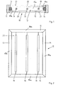
- FIGS. 3 and 4 show a second embodiment of the advertising showcase, which also has the features of the first embodiment.
- the reflector frame 12 by means of two rod-shaped reflector webs 17 and 18, which are parallel to the vertical reflectors 13 and 14 and at a distance therefrom, divided into three approximately equal frame sizes 22, 23 and 24.
- a fluorescent tube 19 is centrally located, wherein the fluorescent tubes 19 are parallel to each other.
- the reflector webs 17 and 18 have a slightly elliptical cross-section, which is aligned so that each of the longer major axis of the ellipse shape to the adjacent Fluorescent tube 19 has. As shown, the ellipse shape may have a point of discontinuity or kink in the end points of the longer major axis, so that the reflector bars 17, 18 each have side edges that are sent to the associated fluorescent tubes 19.
- the exposed convex reflector surfaces 17a and 18a of the reflector webs 17 and 18 may each be designed to be reflective or diffuse reflective.
- Fig. 5 shows a development of the embodiment according to Fig. 3
- this can also in a similar way as a development of the embodiment according to Fig. 1 be used.
- the fluorescent tubes 19 may be spaced apart by a light control sleeve 25, as shown in FIG Fig. 5 is shown by way of example.
- the light control sleeve 25 is characterized in that it has distributed over its circumference areas B of different light transmission.
- the areas B of the light control sleeve 25 facing the lenses 20 allow the light emitted by the fluorescent tube disposed within the light tube 25 to pass only partially through and thus strike the lenses 20 directly.
- the greater part of the light occurs laterally, ie substantially in the center plane of the reflector frame 12 from the light control sleeve 25 and then strikes the reflector surfaces of the reflectors 13, 14, 15 and 16 or the central reflector webs 17 and 18 and only after reflection In this way, the fluorescent tubes 19 are not visible from a viewer of the display case from the outside and it can be the impression of a uniformly illuminated billboards reach.
Description
- Die Erfindung betrifft eine Werbevitrine mit einem Rahmenartigen Gehäuse, zumindest einer auf einem lichtdurchlässigen Träger ausgebildeten Werbefläche und zumindest einer Lichtquelle, die im Inneren des Gehäuses angeordnet, ist und mittels der die Werbefläche auf ihrer Rückseite beleuchtbar ist, wobei im Inneren des Gehäuses im Wesentlichen leistenförmige Reflektoren angeordnet sind, mit denen das von der Lichtquelle ausgehende Licht auf die Rückseite der Werbefläche richtbar ist.
- Eine derartige Werbevitrine findet insbesondere auf öffentlichen Strassen und Plätzen Verwendung und ermöglicht es, auf einer oder mehreren Werbeflächen ein Werbeplakat oder ein sonstiges bildliches Werbeelement in auswechselbarer Weise anzubringen. Um auch bei Dunkelheit die Aufmerksamkeit von Personen zu erregen, ist eine Werbevitrine der genannten Art üblicherweise beleuchtet, indem die Werbefläche hinterleuchtet ist, d.h. im Inneren des Gehäuses sind mehrere Lichtquellen angeordnet, mit denen die Werbeflächen und somit das darauf befindliche Werbeplakat von der Rückseite angestrahlt werden kann.
- Aus ästhetischen Gründen ist es erwünscht, die Werbefläche möglichst gleichmäßig und möglichst hell zu beleuchten. Aus diesem Grunde ist es bekannt, mehrere Lichtquellen in der Werbevitrine zu verwenden. Da bei Verwendung einer Vielzahl von herkömmliche Glühlampen Probleme bezüglich einer übermäßigen Wärmeentwicklung auftreten können und da der lichttechnische Wirkungsgrad derartiger Glühlampen relativ gering ist, werden in der Regel mehrere Leuchtstoffröhren verwendet, die parallel zueinander auf Abstand angeordnet werden.
- Aus der
DE-B-195 28 925 und derGB-A-2 404 485 - Statt die Leuchtstoffröhren in den seitlichen Rahmenteilen des Gehäuses zu verstecken, ist es auch bekannt, die Lichtquelle in der Mitte des Gehäuses anzuordnen, wie es beispielsweise in der
DE-A-30 33 462 gezeigt ist. Um eine übermäßige Beleuchtung der Mitte des Werbeplakates zu vermeiden, muss die Lichtquelle mit Abdeckungen versehen werden, die als Hilfsoptik wirken. Diese Hilfsoptik muss exakt montiert und ausgerichtet werden, wodurch die Montage aufwendig ist. - Wenn dem Träger bzw. der Werbefläche ein Diffuses, z.B. eine Streuscheibe, zugeordnet wird, lassen sich die auf der Werbefläche auftretenden Helligkeitsunterschiede zwar etwas verringern, jedoch verbleiben insbesondere am Rand der Werbefläche weiterhin schwach ausgeleuchtete Bereiche.
- Der Erfindung liegt die Aufgabe zugrunde, eine Werbevitrine der genannten Art zu beschaffen, bei der in einfacher und kostengünstiger Weise eine gleichmäßig ausgeleuchtete Werbefläche erreicht werden kann.
- Diese Aufgabe wird bei einer Werbefläche der genannten Art mit den kennzeichnenden Merkmalen des Anspruchs 1 gelöst. Dabei ist vorgesehen, dass die im Inneren des Gehäuses angeordneten Reflektoren, von denen zumindest einige im Wesentlichen leistenförmig ausgebildet sind, einen umlaufenden, vorzugsweise geschlossenen Rahmen bilden, der zumindest ein Rahmenfeld begrenzt, wobei die Lichtquelle oder die Lichtquellen im Inneren des Rahmenfeldes angeordnet sind. Der Rahmen ist im Wesentlichen eben ausgebildet und liegt in der Ebene des rahmenartigen Gehäuses. Dabei kann der aus den Reflektoren gebildete Rahmen in seinen Abmessungen so an die Abmessungen des Gehäuses ausgebildet sein, dass er auf oder nahe der Innenwandung des Gehäuses angeordnet ist. Die den Rahmen bildenden Reflektoren besitzen auf ihrer zur Mitte des Rahmenfeldes weisenden Seite konvexe Reflektorflächen. Auf diese Weise ist gewährleistet, dass das an den Reflektoren reflektierte Licht vorzugsweise die Randbereiche der Werbefläche beleuchtet, wodurch vermieden ist, dass sich in diesen Randbereiche abgedunkelte Zonen bilden.
- Es hat sich gezeigt, dass mittels der Reflektoren die im Inneren des Gehäuses auftretenden Absorptionsverluste wesentlich verringert werden können, so dass mit einer relativ geringen Anzahl von Lichtquellen eine gleichmäßig Lichtverteilung auf der Werbefläche bei gleichzeitig relativ geringem Energieverbrauch gewährleistet ist. Mittels der Reflektoren lässt sich das Licht innerhalb der Vitrine in geeigneter Weise auf der Werbeflächen verteilern, wobei auch bei der erfindungsgemäßen Werbevitrine dem Träger bzw. der Werbefläche vorzugweise eine Streuscheibe zugeordnet ist.
- Die Montage des von den Reflektoren gebildeten Rahmens ist erleichtert, wenn der Rahmen in Weiterbildung der Erfindung als eine vorgefertigte, eigenstabile Baugruppe ausgebildet ist, die lediglich in das Gehäuses der Werbevitrine eingesetzt und festgelegt werden muss.
- Die den Rahmen bildenden leistenförmigen Reflektoren besitzen vorzugsweise zumindest auf ihrer der Mitte des Rahmenfeldes bzw. der Lichtquelle zugewandten Seite einen stetig gekrümmten, konvexen Querschnitt, der im Wesentlichen halbkreisförmig ausgebildet sein kann, wobei sie konvexe Reflektorfläche zur Mitte des Rahmenfeldes weist. Alternativ können die leistenförmigen Reflektoren einen PolygonQuerschnitt und insbesondere einen im Wesentlichen dreieckigen Querschnitt besitzen, wobei die Basis der Dreiecksform dem äußeren Gehäuse zugewandt ist und die Spitze der Dreiecksform zur Mitte des Rahmens weist. Auf diese Weise sind schräg zur Mittelebene des Rahmens und somit der Werbevitrine verlaufende Reflektorflächen gebildet, die das Licht wirkungsvoll auf die Werbeflächen umlenken.
- Die reflektierenden Oberflächen der leistenförmigen Reflektoren können das Licht entweder gerichtete oder ungerichtet, d.h. diffus reflektierten.
- Der äußere umlaufende Rahmen ist in Weiterbildung der Erfindung durch stabförmige Reflektorstege in mehrere Rahmenfelder unterteilt, wobei in jedem Rahmenfeld zumindest eine Lichtquelle angeordnet ist. Die Rahmenfelder sind vorzugsweise gleich groß und nehmen jeweils eine röhrenförmige Lichtquelle, insbesondere eine Leuchtstoffröhre auf, wobei die röhrenförmigen Lichtquellen parallel zueinander verlaufen. Auf diese Weise ist jede Lichtquelle von einem eigenen Teil-Rahmen umgeben, so dass das von der jeweiligen Lichtquelle abgegebene Licht wirkungsvoll reflektiert und in die gewünschte Richtung umgelenkt werden kann.
- Die stabförmigen Reflektorstege besitzen beispielsweise einen im Wesentlichen rautenförmigen oder rechteckigen Querschnitt, wobei jeweils eine Ecke der Rauten- bzw. Rechteckform der zugeordneten Lichtquelle zugewandt ist. Alternativ können die stabförmigen Reflektoren einen kreis- oder ellipsenförmigen, konvexen Querschnitt besitzen. Bei einer ellipsenförmigen Querschnittsform der Reflektorstege sollte diese so ausgerichtet sein, dass die längere Hauptachse der Ellipse im Wesentlichen in der Rahmenebene liegt und zu der zugeordneten Lichtquelle weist.
- In Weiterbildung der Erfindung kann vorgegehen, dass die Lichtquelle bzw. die Leuchtstoffröhre mit Abstand von einer Lichtsteuerhülse umgeben ist. Die Lichtsteuerhülse besitzt über ihren Umfang verteilte Bereiche unterschiedlicher Lichtdurchlässigkeit. Dabei ist die Lichtsteuerhülse so angeordnet, dass das von der Lichtquelle ausgehende und direkt zum Träger bzw. zur Werbefläche gerichtete Licht durch die Lichtsteuerhülse stärker gedämpft ist. Dies führt dazu, dass ein Großteil von der Lichtquelle ausgehenden Leichtes zunächst im Wesentlichen in oder nahe der Mittelebene des Rahmens verläuft und dann über die Reflektoren auf den Träger bzw. die Werbefläche gerichtet wird. Nur ein Teil des von der Lichtquelle ausgehenden Lichtes wird infolge der Lichtsteuerhülse direkt den Träger bzw. die Werbefläche gerichtet. Auf diese Weise lässt sich eine annähernd einheitliche Lichtverteilung auf der Werbefläche erreichen.
- Weitere Einzelheiten und Merkmale der Erfindung sind aus der folgenden Beschreibung eines Ausführungsbeispiels unter Bezugnahme auf die Zeichnung ersichtlich. Es zeigen:
- Figur 1
- einen schematischen Schnitt durch eine erste Ausführungsform einer erfindungsgemäßen Werbevitrine,
- Figur 2
- eine Seitenansicht des Reflektorrahmens der Werbevitrine gemäß
Fig. 1 , - Figur 3
- einen schematischen Schnitt durch eine zweite Ausführungsform einer erfindungsgemäßen Werbevitrine,
- Figur 4
- eine Seitenansicht des Reflektorrahmens der Werbevitrine gemäß
Fig. 3 und - Figur 5
- eine Weiterbildung der Werbevitrine gemäß
Fig. 3 . - Gemäß
Fig. 1 besitzt eine Werbevitrine 10 ein äußeres rahmenartiges Gehäuse 11, in das ein Reflektorrahmens 12 eingesetzt ist, wie er inFig. 2 dargestellt ist. Der Reflektorrahmen 12 besitzt zwei parallel auf Abstand angeordnete, vertikale, leistenförmige Reflektoren 13 und 14, die an ihrem oberen und ihrem unteren Ende über jeweils einen horizontalen leistenförmigen Reflektor 15 bzw. 16 verbunden sind. Die vier leistenförmigen Reflektoren 13, 14, 15 und 16 bilden somit einen geschlossenen ebenen, rechteckigen Rahmen, der ein rechteckiges Rahmenfeld 22 bildet und umgibt. In dem Rahmenfeld 22 sind drei Leuchtstoffröhren 19 angeordnet, die sich jeweils vertikal zwischen den Reflektoren 15 und 16 erstrecken und parallel zueinander in gegenseitigem seitlichem Abstand angeordnet sind. Die Leuchtstoffröhren 19 sind in nicht dargestellter Weise an eine Spannungsquelle angeschlossen. - Wie
Fig. 1 zeigt, besitzen die den äußeren Rahmen bildenden Reflektoren 13, 14, 15 und 16 jeweils einen im Wesentlichen halbkreisförmigen Querschnitt, wobei die geradlinige Basis der Halbkreisform dem äußeren Gehäuse 11 zugewandt ist und eine konvex gekrümmt Reflektorfläche 13a, 14a, 15a, 16a zur Mitte des Rahmens 12 weist. - Auf beiden Seiten des Rahmens 12 ist in dem Gehäuse 11 jeweils eine lichtdurchlässige Streuscheibe 20 angeordnet, auf deren Außenseite eine Werbefläche 21 zur Anbringung eines Werbeplakats etc. gebildet ist.
- Das von den Leuchtstoffröhren 19 abgegebene Licht trifft teilweise direkt auf die Streuscheiben 20 und durchdringt diese zumindest teilweise. Darüber hinaus fällt das von den Leuchtstoffröhren 19 abgegebene Licht auf die Reflektorflächen 13a, 14a, 15a und 16a der den äußeren Rahmen bildenden Reflektoren 13, 14, 15 und 16, an denen das Licht umgelenkt und ebenfalls auf die Streuscheiben 20 gerichtete wird.
- Die
Figuren 3 und 4 zeigen eine zweite Ausführungsform der Werbevitrine, die ebenfalls die Merkmale der ersten Ausführungsform aufweist. Zusätzlich ist der Reflektorrahmen 12 mittels zweier stabförmiger Reflektorstege 17 und 18, die parallel zu den vertikalen Reflektoren 13 und 14 und auf Abstand zu diesen verlaufen, in drei etwa gleichgroße Rahmenfelder 22, 23 und 24 unterteilt. In jedem Rahmenfeld 22, 23 und 24 ist jeweils mittig eine Leuchtstoffröhre 19 angeordnet, wobei die Leuchtstoffröhren 19 parallel zueinander verlaufen. - Die Reflektorstege 17 und 18 besitzen einen leicht ellipsenförmigen Querschnitt, der so ausgerichtet ist, dass jeweils die längere Hauptachse der Ellipsenform zu der benachbarten Leuchtstoffröhre 19 weist. Wie dargestellt ist, kann die Ellipsenform in den Endpunkten der längeren Hauptachse eine Unstetigkeitsstelle bzw. einen Knick aufweisen, so dass die Reflektorstege 17, 18 jeweils Seitenkanten besitzen, die den zugeordneten Leuchtstoffröhren 19 zugesandt sind. Die freiliegenden konvexen Reflektorflächen 17a und 18a der Reflektorstege 17 und 18 können jeweils spiegelnd oder diffus reflektierend ausgebildet sein.
-
Fig. 5 zeigt eine Weiterbildung der Ausgestaltung gemäßFig. 3 , jedoch kann diese auch in gleichartiger Weise als Weiterbildung der Ausgestaltung gemäßFig. 1 verwendet werden. Um zu verhindern, dass ein übermäßig großer Anteil des von den Leuchtstoffröhren 19 abgegebenen Lichtes direkt auf die Streuscheiben 20 fällt, können die Leuchtstoffröhren 19 mit Abstand jeweils von einer Lichtsteuerhülse 25 umgeben sein, wie es inFig. 5 beispielhaft dargestellt ist. Die Lichtsteuerhülse 25 zeichnet sich dadurch aus, dass sie über ihren Umfang verteilte Bereiche B unterschiedlicher Lichtdurchlässigkeit besitzt. Die den Streuscheiben 20 zugewandten Bereiche B der Lichtsteuerhülse 25 lassen das von der innerhalb der Lichtst.euerhülse 25 angeordneten Leuchtstoffröhre abgegebene Licht nur teilweise hindurch und somit direkt auf die Streuscheiben 20 auftreffen. Der größere Teil des Lichts tritt seitlich, d.h. im Wesentlichen in der Mittelebene des Reflektorrahmens 12 aus der Lichtsteuerhülse 25 auf und trifft dann auf die Reflektorflächen der Reflektoren 13, 14, 15 und 16 bzw. der mittleren Reflektorstege 17 und 18 und gelangt erst nach Reflexion an diesen auf die Streuscheiben 20. Auf diese Weise sind die Leuchtstoffröhren 19 von einem Betrachter der Werbevitrine von der Außenseite nicht erkennbar und es lässt sich der Eindruck einer gleichmäßig ausgeleuchteten Werbeflächen erreichen.
Claims (14)
- Werbevitrine mit einem rahmenartigen Gehäuse (11), zumindest einer auf einem lichtdurchlässigen Träger (20) ausgebildeten Werbefläche (21) und zumindest einer Lichtquelle (19), die im Inneren des Gehäuses (11) angeordnet ist und mittels der die Werbefläche (21) auf ihrer Rückseite beleuchtbar ist, wobei im Inneren des Gehäuses (11) Reflektoren (13, 14, 15, 16) angeordnet sind, mit denen das von der Lichtquelle (19) ausgehende Licht auf die Rückseite der Werbeflächen (21) richtbar ist, dadurch gekennzeichnet, dass die Reflektoren (13, 14, 15, 16) einen umlaufenden Rahmen (12) bilden, der zumindest ein Rahmenfeld (22) begrenzt, dass die Lichtquelle (19) im Inneren des Rahmenfeldes (22) angeordnet ist und dass die den Rahmen (12) bildenden Reflektoren (13, 14, 15, 16) an ihrer zur Mitte des Rahmenfeldes (22) weisenden Seite konvexe Reflektorflächen (13a, 14a, 15a, 16a) besitzen.
- Werbevitrine nach Anspruch 1, dadurch gekennzeichnet, dass die den Rahmen (12) bildenden Reflektoren (13, 14, 15, 16) auf oder nahe der Innenwandung des Gehäuses (11) angeordnet sind.
- Werbevitrine, nach Anspruch 1 oder 2, dadurch gekennzeichnen, dass der Rahmen (12) eine vorgefertigte eigenstabile Baugruppe bildet .
- Werbevitrine nach einem der Ansprüche 1 bis 3, dadurch gekennzeichnet, dass die den Rahmen (12) bildenden Reflektoren (13, 14, 15, 16) einen im Wesentlichen halbkreisförmigen Querschnitt besitzen, wobei die geradlinige Basis der Halbkreisform dem äußeren Gehäuse (11) zugewandt ist und die konvexe Reflektorfläche zur Mitte des Rahmens (12) weist.
- Werbevitrine nach einem der Ansprüche 1 bis 3, dadurch gekennzeichnet, dass die den Rahmen (12) bildenden Reflektoren (13, 14, 15, 16) einen im Wesentlichen dreieckigen Querschnitt besitzen, wobei die Basis der Dreiecksform zudem äußeren Gehäuse (11) zugewandt ist und die Spitze der Dreieckform zur Mitte des Rahmens (12) weist.
- Werbevitrine nach einem der Ansprüche 1 bis 5, dadurch gekennzeichnet, dass der Rahmen (12) durch stabförmige Reflektorstege (17, 18) in mehrere Rahmenfelder (22, 23, 24) unterteilt ist und dass in jedem Rahmenfeld (22, 23, 24) zumindest eine Lichtquelle (19) angeordnet ist.
- Werbevitrine nach Anspruch 6, dadurch gekennzeichnet, dass die Reflektorstege (17, 18) einen im Wesentlichen ellipsenförmigen Querschnitt aufweisen.
- Werbevitrine nach Anspruch 7, dadurch gekennzeichnet, dass der ellipsenförmige Querschnitt der Reflektorstege (17, 18) so ausgerichtet ist, dass die längere Hauptachse der Ellipse im Wesentlichen in der Rahmensebene liegt und zu der benachbarten Lichtquelle weist.
- Werbevitrine nach Anspruch 6, dadurch gekennzeichnet, dass die Reflektorstege (17, 18) einen im Wesentlichen rautenförmigen Querschnitt besitzen.
- Werbevitrine nach einem der Ansprüche 1 bis 9, dadurch gekennzeichnet, dass die Lichtquellen (19) röhrenförmig ausgebildet und insbesondere von Leuchtstoffröhren gebildet sind.
- Werbevitrine nach Anspruch 10, dadurch gekennzeichnet, dass die röhrenförmigen Lichtquellen (19) parallel zueinander verlaufen.
- Werbevitrine nach einem der Ansprüche 1 bis 11, dadurch gekennzeichnet, dass der Träger (20) eine Streuscheibe aufweist.
- Werbevitrine nach einem der Ansprüche 1 bis 12, dadurch gekennzeichnet, dass die Lichtquelle (19) mit Abstand von einer Licht-Steuerhülse (25) umgeben ist, die über ihre Umfangsbereiche unterschiedlicher Lichtdurchlässigkeit aufweist.
- Werbevitrine nach Anspruch 13, dadurch gekennzeichnet, dass die Lichtsteuerhülse (25) so angeordnet ist, dass das von der Lichtquelle (19) ausgehende und direkt zum Träger (20) gerichtete Licht durch die Lichtsteuerscheibe (25) stärker gedämpft ist als das senkrecht dazu gerichtete Licht.
Applications Claiming Priority (2)
| Application Number | Priority Date | Filing Date | Title |
|---|---|---|---|
| DE102004053896A DE102004053896A1 (de) | 2004-11-09 | 2004-11-09 | Werbevitrine |
| PCT/EP2005/011744 WO2006050849A2 (de) | 2004-11-09 | 2005-11-03 | Werbevitrine |
Publications (2)
| Publication Number | Publication Date |
|---|---|
| EP1810268A2 EP1810268A2 (de) | 2007-07-25 |
| EP1810268B1 true EP1810268B1 (de) | 2009-04-29 |
Family
ID=36217202
Family Applications (1)
| Application Number | Title | Priority Date | Filing Date |
|---|---|---|---|
| EP05803312A Not-in-force EP1810268B1 (de) | 2004-11-09 | 2005-11-03 | Werbevitrine |
Country Status (4)
| Country | Link |
|---|---|
| EP (1) | EP1810268B1 (de) |
| AT (1) | ATE430356T1 (de) |
| DE (2) | DE102004053896A1 (de) |
| WO (1) | WO2006050849A2 (de) |
Families Citing this family (2)
| Publication number | Priority date | Publication date | Assignee | Title |
|---|---|---|---|---|
| DE102007037488A1 (de) * | 2007-08-08 | 2009-02-12 | Wall Aktiengesellschaft | Werbevitrine |
| DE202008014694U1 (de) * | 2008-11-05 | 2009-01-15 | Sign-Ware Gmbh & Co. Kg | Displayanordnung sowie Halteprofil dafür |
Family Cites Families (11)
| Publication number | Priority date | Publication date | Assignee | Title |
|---|---|---|---|---|
| DE3033462A1 (de) * | 1980-09-05 | 1982-04-29 | Achim Dipl.-Ing. Dr.-Ing. 1000 Berlin Willing | Beleuchtungsvorrichtung zur hinterleuchtung eines transparentes mit hoher gleichmaessigkeit |
| NL8902677A (nl) * | 1989-10-30 | 1991-05-16 | Janse Lichtreklame Bv | Lichtreklamesysteem met deflector. |
| GB9507725D0 (en) * | 1995-04-13 | 1995-05-31 | Spandex Plc | Illuminated displays |
| DE19528925B4 (de) * | 1995-08-05 | 2004-04-22 | SCHÜCO International KG | Plakatvitrine |
| DE29617657U1 (de) * | 1995-10-12 | 1996-12-05 | Burri Ag | Leuchtkasten für Plakate |
| DE19816988A1 (de) * | 1998-04-17 | 1999-10-21 | M & V Outdoor Schoening Kg | Rahmen einer kantenbeleuchteten Lichtverteilplatte |
| DE19934642A1 (de) * | 1999-07-23 | 2001-02-01 | Adams Ladenbau Heinz Peter Ada | Vorrichtung zum rückwärtigen Beleuchten eines großformatigen, von vorne direkt zu betrachtenden Bildträgers |
| DE20011723U1 (de) * | 2000-06-30 | 2000-11-30 | Berliner Verkehrsbetr E Bvg An | Anzeigevorrichtung für Informationen |
| DE20017314U1 (de) * | 2000-10-10 | 2002-02-21 | Schuetz Dental Gmbh | Vorrichtung zur Dosierung von fliessfähigen Stoffen |
| DE20311094U1 (de) * | 2003-07-18 | 2004-01-08 | Liao, Cheng-Chou | Skateboard mit Lichtverzierung |
| GB2404485A (en) * | 2003-07-26 | 2005-02-02 | Gregory Philip Lawton | Illuminated advertising poster display. |
-
2004
- 2004-11-09 DE DE102004053896A patent/DE102004053896A1/de not_active Withdrawn
-
2005
- 2005-11-03 WO PCT/EP2005/011744 patent/WO2006050849A2/de active Application Filing
- 2005-11-03 DE DE502005007205T patent/DE502005007205D1/de active Active
- 2005-11-03 EP EP05803312A patent/EP1810268B1/de not_active Not-in-force
- 2005-11-03 AT AT05803312T patent/ATE430356T1/de not_active IP Right Cessation
Also Published As
| Publication number | Publication date |
|---|---|
| WO2006050849A3 (de) | 2006-09-28 |
| ATE430356T1 (de) | 2009-05-15 |
| DE502005007205D1 (de) | 2009-06-10 |
| WO2006050849A2 (de) | 2006-05-18 |
| DE102004053896A1 (de) | 2006-05-11 |
| EP1810268A2 (de) | 2007-07-25 |
Similar Documents
| Publication | Publication Date | Title |
|---|---|---|
| DE102011085275B4 (de) | Optisches Element | |
| EP2281143B1 (de) | Leuchte mit getrennten leuchtmitteln für direktbeleuchtung und indirektbeleuchtung | |
| EP2478286B2 (de) | Led-leuchtenelement zur beleuchtung eines lichtkastens mit homogener lichtverteilung | |
| EP1839539A2 (de) | Regalbeleuchtungselement | |
| EP1378771A1 (de) | Innenraumleuchte | |
| DE102009011794B4 (de) | Beleuchtungsanordnung mit Tragprofil | |
| EP2207996A1 (de) | Led-lampe mit diffusor | |
| EP2122232A1 (de) | Beleuchtungseinrichtung | |
| EP2276969B1 (de) | Fahrzeugleuchte | |
| EP2201291B1 (de) | Beleuchtungskörper | |
| DE10041850A1 (de) | Anordnung von lichtabstrahlenden plattenförmigen Elementen | |
| EP3408584B1 (de) | Leuchte mit pyramidenförmiger oder kegelförmiger abdeckung | |
| EP1810268B1 (de) | Werbevitrine | |
| EP2245362B1 (de) | Beleuchtungseinrichtung | |
| EP3408587B1 (de) | Optisches system zum beeinflussen der lichtabgabe einer lichtquelle | |
| DE10011378B4 (de) | Hohllichtleiterleuchte mit indirekter Lichtabstrahlung | |
| EP2258978B1 (de) | Leuchte mit einer lichtdurchlässigen Scheibe | |
| DE102010037630A1 (de) | Leuchte | |
| DE102011000702A1 (de) | Rollfeldverkehrszeichen | |
| DE202013103401U1 (de) | Freiformoptik für LED-Straßenleuchten | |
| WO2011107479A1 (de) | Leuchte mit lichtausrichtungselementen | |
| DE10018499B4 (de) | Flachleuchte mit gleichmäßiger Abstrahlcharakteristik | |
| CH690247A5 (de) | Leuchtkörperaufbau. | |
| EP3329178B1 (de) | Lichtleiterelement | |
| DE3129038A1 (de) | Hinweisleuchte |
Legal Events
| Date | Code | Title | Description |
|---|---|---|---|
| PUAI | Public reference made under article 153(3) epc to a published international application that has entered the european phase |
Free format text: ORIGINAL CODE: 0009012 |
|
| 17P | Request for examination filed |
Effective date: 20070518 |
|
| AK | Designated contracting states |
Kind code of ref document: A2 Designated state(s): AT BE BG CH CY CZ DE DK EE ES FI FR GB GR HU IE IS IT LI LT LU LV MC NL PL PT RO SE SI SK TR |
|
| GRAP | Despatch of communication of intention to grant a patent |
Free format text: ORIGINAL CODE: EPIDOSNIGR1 |
|
| DAX | Request for extension of the european patent (deleted) | ||
| GRAS | Grant fee paid |
Free format text: ORIGINAL CODE: EPIDOSNIGR3 |
|
| GRAA | (expected) grant |
Free format text: ORIGINAL CODE: 0009210 |
|
| AK | Designated contracting states |
Kind code of ref document: B1 Designated state(s): AT BE BG CH CY CZ DE DK EE ES FI FR GB GR HU IE IS IT LI LT LU LV MC NL PL PT RO SE SI SK TR |
|
| REG | Reference to a national code |
Ref country code: GB Ref legal event code: FG4D Free format text: NOT ENGLISH |
|
| REG | Reference to a national code |
Ref country code: CH Ref legal event code: EP |
|
| REF | Corresponds to: |
Ref document number: 502005007205 Country of ref document: DE Date of ref document: 20090610 Kind code of ref document: P |
|
| REG | Reference to a national code |
Ref country code: IE Ref legal event code: FG4D |
|
| NLV1 | Nl: lapsed or annulled due to failure to fulfill the requirements of art. 29p and 29m of the patents act | ||
| PG25 | Lapsed in a contracting state [announced via postgrant information from national office to epo] |
Ref country code: ES Free format text: LAPSE BECAUSE OF FAILURE TO SUBMIT A TRANSLATION OF THE DESCRIPTION OR TO PAY THE FEE WITHIN THE PRESCRIBED TIME-LIMIT Effective date: 20090809 Ref country code: LT Free format text: LAPSE BECAUSE OF FAILURE TO SUBMIT A TRANSLATION OF THE DESCRIPTION OR TO PAY THE FEE WITHIN THE PRESCRIBED TIME-LIMIT Effective date: 20090429 Ref country code: FI Free format text: LAPSE BECAUSE OF FAILURE TO SUBMIT A TRANSLATION OF THE DESCRIPTION OR TO PAY THE FEE WITHIN THE PRESCRIBED TIME-LIMIT Effective date: 20090429 |
|
| PG25 | Lapsed in a contracting state [announced via postgrant information from national office to epo] |
Ref country code: LV Free format text: LAPSE BECAUSE OF FAILURE TO SUBMIT A TRANSLATION OF THE DESCRIPTION OR TO PAY THE FEE WITHIN THE PRESCRIBED TIME-LIMIT Effective date: 20090429 Ref country code: SE Free format text: LAPSE BECAUSE OF FAILURE TO SUBMIT A TRANSLATION OF THE DESCRIPTION OR TO PAY THE FEE WITHIN THE PRESCRIBED TIME-LIMIT Effective date: 20090729 Ref country code: SI Free format text: LAPSE BECAUSE OF FAILURE TO SUBMIT A TRANSLATION OF THE DESCRIPTION OR TO PAY THE FEE WITHIN THE PRESCRIBED TIME-LIMIT Effective date: 20090429 Ref country code: NL Free format text: LAPSE BECAUSE OF FAILURE TO SUBMIT A TRANSLATION OF THE DESCRIPTION OR TO PAY THE FEE WITHIN THE PRESCRIBED TIME-LIMIT Effective date: 20090429 Ref country code: PL Free format text: LAPSE BECAUSE OF FAILURE TO SUBMIT A TRANSLATION OF THE DESCRIPTION OR TO PAY THE FEE WITHIN THE PRESCRIBED TIME-LIMIT Effective date: 20090429 Ref country code: IS Free format text: LAPSE BECAUSE OF FAILURE TO SUBMIT A TRANSLATION OF THE DESCRIPTION OR TO PAY THE FEE WITHIN THE PRESCRIBED TIME-LIMIT Effective date: 20090829 |
|
| REG | Reference to a national code |
Ref country code: IE Ref legal event code: FD4D |
|
| PG25 | Lapsed in a contracting state [announced via postgrant information from national office to epo] |
Ref country code: RO Free format text: LAPSE BECAUSE OF FAILURE TO SUBMIT A TRANSLATION OF THE DESCRIPTION OR TO PAY THE FEE WITHIN THE PRESCRIBED TIME-LIMIT Effective date: 20090429 Ref country code: DK Free format text: LAPSE BECAUSE OF FAILURE TO SUBMIT A TRANSLATION OF THE DESCRIPTION OR TO PAY THE FEE WITHIN THE PRESCRIBED TIME-LIMIT Effective date: 20090429 Ref country code: EE Free format text: LAPSE BECAUSE OF FAILURE TO SUBMIT A TRANSLATION OF THE DESCRIPTION OR TO PAY THE FEE WITHIN THE PRESCRIBED TIME-LIMIT Effective date: 20090429 Ref country code: CZ Free format text: LAPSE BECAUSE OF FAILURE TO SUBMIT A TRANSLATION OF THE DESCRIPTION OR TO PAY THE FEE WITHIN THE PRESCRIBED TIME-LIMIT Effective date: 20090429 Ref country code: IE Free format text: LAPSE BECAUSE OF FAILURE TO SUBMIT A TRANSLATION OF THE DESCRIPTION OR TO PAY THE FEE WITHIN THE PRESCRIBED TIME-LIMIT Effective date: 20090429 |
|
| PG25 | Lapsed in a contracting state [announced via postgrant information from national office to epo] |
Ref country code: SK Free format text: LAPSE BECAUSE OF FAILURE TO SUBMIT A TRANSLATION OF THE DESCRIPTION OR TO PAY THE FEE WITHIN THE PRESCRIBED TIME-LIMIT Effective date: 20090429 |
|
| PLBE | No opposition filed within time limit |
Free format text: ORIGINAL CODE: 0009261 |
|
| STAA | Information on the status of an ep patent application or granted ep patent |
Free format text: STATUS: NO OPPOSITION FILED WITHIN TIME LIMIT |
|
| 26N | No opposition filed |
Effective date: 20100201 |
|
| BERE | Be: lapsed |
Owner name: WALL A.G. Effective date: 20091130 |
|
| REG | Reference to a national code |
Ref country code: HU Ref legal event code: AG4A Ref document number: E007274 Country of ref document: HU |
|
| PG25 | Lapsed in a contracting state [announced via postgrant information from national office to epo] |
Ref country code: MC Free format text: LAPSE BECAUSE OF NON-PAYMENT OF DUE FEES Effective date: 20091130 |
|
| REG | Reference to a national code |
Ref country code: CH Ref legal event code: PL |
|
| GBPC | Gb: european patent ceased through non-payment of renewal fee |
Effective date: 20091103 |
|
| REG | Reference to a national code |
Ref country code: FR Ref legal event code: ST Effective date: 20100730 |
|
| PG25 | Lapsed in a contracting state [announced via postgrant information from national office to epo] |
Ref country code: FR Free format text: LAPSE BECAUSE OF NON-PAYMENT OF DUE FEES Effective date: 20091130 Ref country code: CH Free format text: LAPSE BECAUSE OF NON-PAYMENT OF DUE FEES Effective date: 20091130 Ref country code: BE Free format text: LAPSE BECAUSE OF NON-PAYMENT OF DUE FEES Effective date: 20091130 Ref country code: GR Free format text: LAPSE BECAUSE OF FAILURE TO SUBMIT A TRANSLATION OF THE DESCRIPTION OR TO PAY THE FEE WITHIN THE PRESCRIBED TIME-LIMIT Effective date: 20090730 Ref country code: LI Free format text: LAPSE BECAUSE OF NON-PAYMENT OF DUE FEES Effective date: 20091130 |
|
| PG25 | Lapsed in a contracting state [announced via postgrant information from national office to epo] |
Ref country code: GB Free format text: LAPSE BECAUSE OF NON-PAYMENT OF DUE FEES Effective date: 20091103 |
|
| PG25 | Lapsed in a contracting state [announced via postgrant information from national office to epo] |
Ref country code: AT Free format text: LAPSE BECAUSE OF NON-PAYMENT OF DUE FEES Effective date: 20091103 |
|
| PGFP | Annual fee paid to national office [announced via postgrant information from national office to epo] |
Ref country code: BG Payment date: 20101018 Year of fee payment: 6 Ref country code: HU Payment date: 20101102 Year of fee payment: 6 |
|
| PG25 | Lapsed in a contracting state [announced via postgrant information from national office to epo] |
Ref country code: IT Free format text: LAPSE BECAUSE OF FAILURE TO SUBMIT A TRANSLATION OF THE DESCRIPTION OR TO PAY THE FEE WITHIN THE PRESCRIBED TIME-LIMIT Effective date: 20090429 |
|
| PG25 | Lapsed in a contracting state [announced via postgrant information from national office to epo] |
Ref country code: LU Free format text: LAPSE BECAUSE OF NON-PAYMENT OF DUE FEES Effective date: 20091103 |
|
| PG25 | Lapsed in a contracting state [announced via postgrant information from national office to epo] |
Ref country code: CY Free format text: LAPSE BECAUSE OF FAILURE TO SUBMIT A TRANSLATION OF THE DESCRIPTION OR TO PAY THE FEE WITHIN THE PRESCRIBED TIME-LIMIT Effective date: 20090429 |
|
| PG25 | Lapsed in a contracting state [announced via postgrant information from national office to epo] |
Ref country code: HU Free format text: LAPSE BECAUSE OF NON-PAYMENT OF DUE FEES Effective date: 20111104 |
|
| PG25 | Lapsed in a contracting state [announced via postgrant information from national office to epo] |
Ref country code: PT Free format text: LAPSE BECAUSE OF FAILURE TO SUBMIT A TRANSLATION OF THE DESCRIPTION OR TO PAY THE FEE WITHIN THE PRESCRIBED TIME-LIMIT Effective date: 20090929 |
|
| PG25 | Lapsed in a contracting state [announced via postgrant information from national office to epo] |
Ref country code: BG Free format text: LAPSE BECAUSE OF NON-PAYMENT OF DUE FEES Effective date: 20120630 |
|
| REG | Reference to a national code |
Ref country code: DE Ref legal event code: R082 Ref document number: 502005007205 Country of ref document: DE Representative=s name: BOEHMERT & BOEHMERT ANWALTSPARTNERSCHAFT MBB -, DE Ref country code: DE Ref legal event code: R081 Ref document number: 502005007205 Country of ref document: DE Owner name: WALL GMBH, DE Free format text: FORMER OWNER: WALL AKTIENGESELLSCHAFT, 10117 BERLIN, DE |
|
| PGFP | Annual fee paid to national office [announced via postgrant information from national office to epo] |
Ref country code: TR Payment date: 20160929 Year of fee payment: 12 |
|
| PGFP | Annual fee paid to national office [announced via postgrant information from national office to epo] |
Ref country code: DE Payment date: 20181129 Year of fee payment: 14 |
|
| REG | Reference to a national code |
Ref country code: DE Ref legal event code: R119 Ref document number: 502005007205 Country of ref document: DE |
|
| PG25 | Lapsed in a contracting state [announced via postgrant information from national office to epo] |
Ref country code: DE Free format text: LAPSE BECAUSE OF NON-PAYMENT OF DUE FEES Effective date: 20200603 |
|
| PG25 | Lapsed in a contracting state [announced via postgrant information from national office to epo] |
Ref country code: TR Free format text: LAPSE BECAUSE OF NON-PAYMENT OF DUE FEES Effective date: 20171103 |