EP1809775B1 - Vorrichtung zum kühlen von langen gegenständen - Google Patents
Vorrichtung zum kühlen von langen gegenständen Download PDFInfo
- Publication number
- EP1809775B1 EP1809775B1 EP05797187A EP05797187A EP1809775B1 EP 1809775 B1 EP1809775 B1 EP 1809775B1 EP 05797187 A EP05797187 A EP 05797187A EP 05797187 A EP05797187 A EP 05797187A EP 1809775 B1 EP1809775 B1 EP 1809775B1
- Authority
- EP
- European Patent Office
- Prior art keywords
- gas
- cooling
- diameter
- cladding tube
- nozzles
- Prior art date
- Legal status (The legal status is an assumption and is not a legal conclusion. Google has not performed a legal analysis and makes no representation as to the accuracy of the status listed.)
- Expired - Lifetime
Links
Images
Classifications
-
- C—CHEMISTRY; METALLURGY
- C21—METALLURGY OF IRON
- C21D—MODIFYING THE PHYSICAL STRUCTURE OF FERROUS METALS; GENERAL DEVICES FOR HEAT TREATMENT OF FERROUS OR NON-FERROUS METALS OR ALLOYS; MAKING METAL MALLEABLE, e.g. BY DECARBURISATION OR TEMPERING
- C21D1/00—General methods or devices for heat treatment, e.g. annealing, hardening, quenching or tempering
- C21D1/18—Hardening; Quenching with or without subsequent tempering
- C21D1/19—Hardening; Quenching with or without subsequent tempering by interrupted quenching
- C21D1/20—Isothermal quenching, e.g. bainitic hardening
-
- C—CHEMISTRY; METALLURGY
- C21—METALLURGY OF IRON
- C21D—MODIFYING THE PHYSICAL STRUCTURE OF FERROUS METALS; GENERAL DEVICES FOR HEAT TREATMENT OF FERROUS OR NON-FERROUS METALS OR ALLOYS; MAKING METAL MALLEABLE, e.g. BY DECARBURISATION OR TEMPERING
- C21D1/00—General methods or devices for heat treatment, e.g. annealing, hardening, quenching or tempering
- C21D1/18—Hardening; Quenching with or without subsequent tempering
- C21D1/19—Hardening; Quenching with or without subsequent tempering by interrupted quenching
-
- C—CHEMISTRY; METALLURGY
- C21—METALLURGY OF IRON
- C21D—MODIFYING THE PHYSICAL STRUCTURE OF FERROUS METALS; GENERAL DEVICES FOR HEAT TREATMENT OF FERROUS OR NON-FERROUS METALS OR ALLOYS; MAKING METAL MALLEABLE, e.g. BY DECARBURISATION OR TEMPERING
- C21D2211/00—Microstructure comprising significant phases
- C21D2211/002—Bainite
-
- C—CHEMISTRY; METALLURGY
- C21—METALLURGY OF IRON
- C21D—MODIFYING THE PHYSICAL STRUCTURE OF FERROUS METALS; GENERAL DEVICES FOR HEAT TREATMENT OF FERROUS OR NON-FERROUS METALS OR ALLOYS; MAKING METAL MALLEABLE, e.g. BY DECARBURISATION OR TEMPERING
- C21D9/00—Heat treatment, e.g. annealing, hardening, quenching or tempering, adapted for particular articles; Furnaces therefor
- C21D9/40—Heat treatment, e.g. annealing, hardening, quenching or tempering, adapted for particular articles; Furnaces therefor for rings; for bearing races
Definitions
- the invention relates to a device for cooling long objects according to the preamble of claim 1.
- the length expansion is substantially greater than the dimensions in the width and / or in height.
- rapid quenching is often required to suitably transform microstructures.
- the object of the invention is to propose a device with which long or endless objects can be gas-cooled reliably, quickly and economically. This object is achieved by a device with the features of claim 1. Embodiments of the invention are objects of dependent claims.
- the device according to the invention has two differently dimensioned chambers or regions, wherein in the first chamber (nozzle region) a plurality of nozzles are provided, which blow cold gas jets onto the object to be cooled.
- the second region (cladding tube) is a relatively long dusentransports cladding and enclosing the object to be cooled over a longer range.
- the gap formed between the object to be cooled and the inner wall of the cladding tube flows through the cold gas which has been sprayed from the nozzles towards the object and thus either further cools the article as the article moves or cools it in the direction of the gas when the direction of movement of the object is against the gas direction.
- the cross section of the cladding tube is adapted to the object to be cooled. If the object is round, the cladding tube is also cylindrical, rectangular in the case of rectangular bars. The cladding closely encloses the article so that the cooling gas is conducted close to the article.
- the invention may be located on one side of the nozzle portion, a sealing region which rests relatively close to the object to be cooled and prevents refrigerant gas escaping in this direction. This has the advantage that the cooling gas flows only in the preferred direction.
- the cladding tube has a smaller diameter than the nozzle area.
- N 2 , H 2 , helium or N 2 H 2 mixtures, N 2 -helium mixtures, H 2 -helium mixtures or thermal mixtures of N 2 , H 2 and helium are advantageous.
- the gases can be reused.
- the reuse and cooling of the gases in one heat exchanger is worthwhile for a further or several passes.
- less expensive gases such as N 2 or CO 2 can be dispensed with.
- the dimensions of the objects to be cooled can range from wires of about 1 mm in diameter to tubes of any diameter, that is from a few centimeters to a few meters in diameter.
- Starting temperatures may be in the range of 400 to 1400 ° C, the starting temperature being dependent on the alloy and quenching requirements.
- the gas pressures during spraying can be between 0 and 10 bar.
- the nozzles for discharging the gas jets are preferably oriented so as to blow in the radial direction on the object to be cooled, so that the entire circumference of the object is uniformly applied.
- the pressure within the spray nozzles is between 1 and 10 bar, preferably between 1 and 3 bar, e.g. at 2 bar, which then impact or impact velocities between 70 and 200 m / sec., Preferably between 100 and 180 m / s, can be achieved. However, speeds up to the speed of sound are also possible. For certain types of nozzles, the impact speeds may even be greater than the speed of sound.
- the preferred distance between the article to be cooled and the gas-carrying casing is chosen such that the gas velocity in the cladding tube gap is between one and ten meters per second (preferably between 3 and 6 m / s).
- the direction of the gas can run both with the product direction and against the product direction. If such a plant is connected to a heating furnace or to a device for casting, drawing or producing the metal, this object will always move in one direction.
- the gas may then flow parallel thereto or in the opposite direction. Preferably, the gas flow in the opposite direction, because then a more uniform cooling is achieved. If such an opposite river can not be reached, the river can also be in the direction of the product.
- the gap between the cooling jacket and the object should not be so small that a significant back pressure arises and prevents the gas from flowing off, so that a significant back pressure is created with respect to the gas flowing from the nozzles.
- the gas volume should be controlled so that the gas leaving the unit is not unduly hot.
- Turbulence generating units can be installed inside the pipe, which destroy the laminar flow, create turbulence and therefore lead to better cooling.
- the length of the cladding tube is chosen so that, together with the product speed, the intended final temperature of the product is achieved. This is possible due to greater length if a lower end temperature is desired.
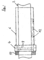
- the figure shows schematically the object 2 to be cooled, in this case a rod or a tube, within the cooling device according to the invention.
- the cooling device according to the invention comprises a nozzle region 2 and a cladding tube 6, which adjoins the nozzle region 4 in the nozzle region 4, the nozzles 8 are shown schematically.
- a sealing region 10 connects, which rests relatively close to the object 2 and prevents leakage of the gas to the left.
- swirling elements 12 which may also extend over the entire circumference of the cladding tube.
- the function is the following:
- the object 2 to be cooled moves either from left to right or from right to left through the device according to the invention.
- cold gas is blown through the nozzles 8 onto the object 2.
- the object 2 cools strongly in the nozzle area 4.
- the gas then flows through the gap between the article 2 and the cladding tube 6 to the right, where it further cools the article 2.
- Preferred dimensions are:
- the length of the cladding tube is 2 to 50, preferably 30 to 50 times as large as its diameter, so for example between 0.1 and 1 m.
- the gaps between the object 2 and the cladding tube 6 are between 5 and 20 mm.
- the nozzle diameters are for example 1.2 mm.
- the length of the nozzle area is a few centimeters to decimeters.
Landscapes
- Chemical & Material Sciences (AREA)
- Engineering & Computer Science (AREA)
- Physics & Mathematics (AREA)
- Thermal Sciences (AREA)
- Crystallography & Structural Chemistry (AREA)
- Mechanical Engineering (AREA)
- Materials Engineering (AREA)
- Metallurgy (AREA)
- Organic Chemistry (AREA)
- Heat Treatments In General, Especially Conveying And Cooling (AREA)
- Heat Treatment Of Strip Materials And Filament Materials (AREA)
Description
- Die Erfindung betrifft eine Vorrichtung zum Kühlen von langen Gegenständen nach dem Oberbegriff des Anspruchs 1. Unter langen Gegenständen werden Drähte, Rohre, Stäbe, Federstähle, Platten und ähnliche Gegenstände verstanden, deren Längesausdehnung wesentlich größer ist, als die Ausdehnungen in der Breite und/oder in der Höhe. Beim Herstellen (Gießen oder Ziehen) solcher "endloser" Gegenstände oder nach der Wärmebehandlung ist häufig ein schnelles Abkühlen (Quenchen) erforderlich, um Gefüge geeignet umzuwandeln.
- Aus dem Artikel: "An evaluation of multiple-jet impingement gas quenching of steel rings" von J. Ferrari, N. Lior, vom 19. Januar 2002 ist eine Vorrichtung bekannt, bei der Kugellager in ein Feld von Gasdüsen gebracht werden. Zum schnellen Abkühlen oder Quenchen der heißen Kugellager werden durch eine Vielzahl von Düsen Gasströme auf die Gegenstände geleitet, um diese schnell abzukühlen. Diese Vorrichtung eignet sich nur für relativ kompakte Gegenstände, die keine zu großen Ausdehnungen haben. Aus der Patentanmeldung
US 2002/0195753 ist eine Vorrichtung zum Kühlen von langen Cregenstanden bekannt. - Aufgabe der Erfindung ist es, eine Vorrichtung vorzuschlagen, mit der lange oder endlose Gegenstände zuverlässig, schnell und wirtschaftlich gasgekühlt werden können. Diese Aufgabe wird erfindungsgemäß gelöst von einer Vorrichtung mit den Merkmalen des Anspruchs 1. Ausgestaltungen der Erfindung sind Gegenstände von Unteransprüchen.
- Die erfindungsgemäße Vorrichtung weist zwei unterschiedlich dimensionierte Kammern oder Bereiche auf, wobei in der ersten Kammer (Düsenbereich) eine Vielzahl von Düsen vorgesehen sind, welche Kaltgasjets auf den zu kühlenden Gegenstand blasen. Der zweite Bereich (Hüllrohr) ist ein relativ lang es dusenfreies Hüllrohr und umschließt den zu kühlenden Gegenstand über einen längeren Bereich. Der sich zwischen dem zu kühlenden Gegenstand und der Innenwand des Hüllrohrs bildende Spalt wird vom Kaltgas durchströmt, welches aus den Düsen zum Gegenstand hin gesprüht wurde und kühlt so den Gegenstand entweder weiter ab, wenn sich der Gegenstand in Richtung des Gases bewegt oder kühlt ihn vor, wenn die Bewegungsrichtung des Gegenstandes gegen die Gasrichtung verläuft. Durch eine relativ enge Ausbildung des Spaltes zwischen der Kühlkammer und dem zu kühlenden Gegenstand kann ein relativ inniger Kontakt zwischen Gas und Gegenstand erreicht werden, so dass die Kühlwirkung des Gases relativ gut ausgenutzt wird. Der Querschnitt des Hüllrohres ist dem zu kühlenden Gegenstand angepasst. Ist der Gegenstand rund, ist auch das Hüllrohr zylindrisch, bei rechteckigen Stäben rechteckig. Das Hüllrohr umschließt den Gegenstand eng, so dass das Kühlgas nahe am Gegenstand geführt wird.
- In einer Ausführung der Erfindung kann an einer Seite des Düsenbereichs ein Dichtbereich liegen, der relativ eng an den zu kühlenden Gegenstand anliegt und verhindert, dass Kühlgas in diese Richtung entweicht. Dies hat den Vorteil, dass das Kühlgas nur in die bevorzugte Richtung fließt.
- In einer bevorzugten Ausführung hat das Hüllrohr einen kleineren Durchmesser als der Düsen-Bereich. Dadurch wird der Kontakt zwischen Gas und zu kühlendem Gegenstand noch inniger. Die Gasgeschwindigkeit wird durch den kleineren Spalt bei gleichem Druck größer und die Kühlwirkung verstärkt.
- Als Gase können alle bekannten technischen Gase eingesetzt werden. Vorteilhaft sind N2, H2, Helium oder N2H2-Mischungen, N2-Helium-Mischungen, H2-Helium-Mischungen oder Temärmischungen aus N2, H2 und Helium.
- Bevorzugt können die Gase wieder verwendet werden. Insbesondere bei Helium, Wasserstoff oder anderen teuren Gasen lohnt sich die Wiederverwendung und Abkühlung der Gase in einem Wärmetauscher für einen weiteren oder mehrere Durchläufe. Bei preiswerteren Gasen wie N2 oder CO2 kann darauf verzichtet werden.
- Die Dimensionen der zu kühlenden Gegenstände können von Drähten mit ca. 1 mm Durchmesser angefangen bis zu Röhren von beliebigen Durchmessern reichen, also von einigen Zentimetern bis zu einigen Metern im Durchmesser. Starttemperaturen können im Bereich von 400 bis 1400 °C liegen, wobei die Starttemperatur abhängig ist von der Legierung und den Erfordernissen beim Quenchen. Die Gasdrücke beim Einsprühen können zwischen 0 und 10 bar liegen.
- Die Düsen zum Abgeben der Gasjets sind bevorzugt so orientiert, dass sie in radialer Richtung auf den zu kühlenden Gegenstand blasen, so dass der gesamte Umfang des Gegenstands gleichmäßig beaufschlagt wird.
- Der Druck innerhalb der Aufsprühdüsen liegt zwischen 1 und 10 bar, bevorzugt zwischen 1 und 3 bar, z.B. bei 2 bar, wobei dann Aufstoß- oder Auftreff-Geschwindigkeiten zwischen 70 und 200 m/sec., bevorzugt zwischen 100 und 180 m/s, erreicht werden. Möglich sind allerdings auch Geschwindigkeiten bis zur Schallgeschwindigkeit. Für bestimmte Düsentypen können die Aufstoß-Geschwindigkeiten sogar größer als die Schallgeschwindigkeit sein.
- Der bevorzugte Abstand zwischen dem zu kühlenden Gegenstand und der gasführenden Hülle ist so gewählt, dass die Gasgeschwindigkeit im Hüllrohrspalt zwischen einem und zehn Metern pro Sekunde (bevorzugt zwischen 3 und 6 m/s) liegt.
- Die Richtung des Gases kann sowohl gleich mit der Produktrichtung als auch gegen die Produktrichtung verlaufen. Wenn eine solche Anlage an einen Wärmeofen oder an eine Einrichtung zum Gießen, Ziehen oder Erzeugen des Metalls angeschlossen ist, wird dieser Gegenstand sich stets in eine Richtung bewegen. Das Gas kann dann parallel dazu oder in Gegenrichtung fließen. Bevorzugt ist der Gasfluss in Gegenrichtung, weil dann eine gleichmäßigere Kühlung erreicht wird. Sollte so ein gegenläufiger Fluss nicht erreichbar sein, kann der Fluss auch in Produktrichtung erfolgen.
- Sollte die Länge der Kühlvorrichtung nicht ausreichen, um den Gegenstand ausreichend abzukühlen, können mehrere solcher Einheiten hintereinander geschaltet werden, um eine ausreichende Kühlkapazität zu erreichen.
- Andererseits sollte der Spalt zwischen dem Kühlmantel und dem Gegenstand nicht so klein sein, dass ein erheblicher Gegendruck entsteht und das Gas am Abfließen hindert, so dass ein bedeutender Gegendruck gegenüber den aus den Düsen fließenden Gas entsteht. Auf der anderen Seite sollte das Gasvolumen so kontrolliert sein, dass das Gas, welches die Einheit verlässt, nicht unzulässig heiß ist.
- Innerhalb des Rohres können turbulenzerzeugende Einheiten (Verwirbelungselemente) installiert werden, die den laminaren Fluss zerstören, Turbulenzen erzeugen und deshalb zu einer besseren Kühlung führen.
- Die Länge des Hüllrohres wird so gewählt, dass zusammen mit der Produktgeschwindigkeit die vorgesehene Endtemperatur des Produkts erreicht wird. Dies ist möglich durch größere Länge, wenn eine tiefere Endtemperatur gewünscht wird.
- Eine Ausführungsform der Erfindung wird anhand einer Figur näher erläutert. Die Figur zeigt schematisch den zu kühlenden Gegenstand 2, hier ein Stab oder ein Rohr, innerhalb der erfindungsgemäßen Kühleinrichtung. Die erfindungsgemäße Kühleinrichtung enthält einen Düsenbereich 2 und ein Hüllrohr 6, welches sich an den Düsenbereich 4 anschließt im Düsenbereich 4 sind die Düsen 8 schematisch eingezeichnet. Links vom Düsenbereich 4 schließt sich ein Dichtbereich 10 an, der relativ eng an dem Gegenstand 2 anliegt und ein Abströmen des Gases nach links verhindert. Unten sind Verwirbelungselemente 12 gezeigt, die sich auch über den ganzen Umfang des Hüllrohrs erstrecken können.
- Der zu kühlende Gegenstand 2 bewegt sich entweder von links nach rechts oder von rechts nach links durch die erfindungsgemäße Vorrichtung. Zum Kühlen wird kaltes Gas durch die Düsen 8 auf den Gegenstand 2 geblasen. Dadurch kühlt sich der Gegenstand 2 im Düsenbereich 4 stark ab. Das Gas fließt dann durch den Spalt zwischen dem Gegenstand 2 und dem Hüllrohr 6 nach rechts, wobei es den Gegenstand 2 weiter kühlt.
- Die Länge des Hüllrohrs ist 2 bis 50, bevorzugt 30 bis 50 mal so groß wie sein Durchmesser, liegt also zum Beispiel zwischen 0,1 und 1 m. Die Spalte zwischen dem Gegenstand 2 und dem Hüllrohr 6 liegen zwischen 5 und 20 mm. Die Düsendurchmesser liegen z.B. bei 1,2 mm. Die Länge des Düsenbereichs liegt bei einigen Zentimetern bis Dezimetern.
- Für einen guten Wärmeübertragungskoeffizienten sollte gelten:
d = 0,1 bis 0,2 x H bevorzugt: d = 0,18 H und t = 1 bis 1,5 x H bevorzugt: t = 1,3 H mit d = Jetdurchmesser in m
H = Abstand zum Gegenstand
t = Abstand der Düsenmitten voneinander
Claims (4)
- Vorrichtung zum Kühlen von langen Gegenständen (2) mit einem Düsenbereich (4), dessen Durchmesser größer ist als der Durchmesser des Gegenstands (2), der eine Vielzahl von Düsen (8) enthält, die ein Kühlgas auf den Gegenstand (2) blasen, gekennzeichnet durch ein düsenfreies Hüllrohr (6), dessen Durchmesser gleich oder kleiner als der Durchmesser des Düsenbereichs (4) ist.
- Vorrichtung nach Anspruch 1, dadurch gekennzeichnet, dass ein Dichtbereich (10) vorgesehen ist.
- Vorrichtung nach Anspruch 1, dadurch gekennzeichnet, dass das Hüllrohr (6) eine Länge von 0,1 bis 1 m hat.
- Vorrichtung nach einem der vorhergehenden Ansprüche, dadurch gekennzeichnet, dass das Kühlgas wieder verwendet wird.
Applications Claiming Priority (2)
| Application Number | Priority Date | Filing Date | Title |
|---|---|---|---|
| DE102004054627A DE102004054627A1 (de) | 2004-11-11 | 2004-11-11 | Vorrichtung zum Kühlen von langen Gegenständen |
| PCT/EP2005/011447 WO2006050814A2 (de) | 2004-11-11 | 2005-10-25 | Vorrichtung zum kühlen von langen gegenständen |
Publications (2)
| Publication Number | Publication Date |
|---|---|
| EP1809775A2 EP1809775A2 (de) | 2007-07-25 |
| EP1809775B1 true EP1809775B1 (de) | 2009-01-14 |
Family
ID=35355624
Family Applications (1)
| Application Number | Title | Priority Date | Filing Date |
|---|---|---|---|
| EP05797187A Expired - Lifetime EP1809775B1 (de) | 2004-11-11 | 2005-10-25 | Vorrichtung zum kühlen von langen gegenständen |
Country Status (7)
| Country | Link |
|---|---|
| US (1) | US7497984B2 (de) |
| EP (1) | EP1809775B1 (de) |
| AT (1) | ATE420979T1 (de) |
| BR (1) | BRPI0517300B1 (de) |
| DE (2) | DE102004054627A1 (de) |
| ES (1) | ES2321120T3 (de) |
| WO (1) | WO2006050814A2 (de) |
Families Citing this family (2)
| Publication number | Priority date | Publication date | Assignee | Title |
|---|---|---|---|---|
| US9290823B2 (en) | 2010-02-23 | 2016-03-22 | Air Products And Chemicals, Inc. | Method of metal processing using cryogenic cooling |
| EP2933342A1 (de) * | 2014-04-15 | 2015-10-21 | Böhler-Uddeholm Precision Strip GmbH | Verfahren und Vorrichtung zur Herstellung eines Bandstahls mit bainitischer Gefügestruktur |
Family Cites Families (5)
| Publication number | Priority date | Publication date | Assignee | Title |
|---|---|---|---|---|
| US3675908A (en) * | 1971-01-04 | 1972-07-11 | Ajax Magnethermic Corp | Quenching device |
| JPS5767134A (en) * | 1980-10-09 | 1982-04-23 | Nippon Steel Corp | Method and installation for continuous annealing method of cold-rolled steel strip |
| DE3234863C2 (de) * | 1982-09-21 | 1986-04-10 | Messer Griesheim Gmbh, 6000 Frankfurt | Verfahren und Vorrichtung zum Blankglühen von metallischen Werkstücken mit Stickstoff als Schutzgas |
| US6656413B2 (en) * | 2001-06-21 | 2003-12-02 | Can-Eng Furnaces Ltd | Method and apparatus for quenching metal workpieces |
| FR2844809B1 (fr) * | 2002-09-20 | 2007-06-29 | Air Liquide | Procede de refroidissement rapide de pieces par transfert convectif et radiatif |
-
2004
- 2004-11-11 DE DE102004054627A patent/DE102004054627A1/de not_active Withdrawn
-
2005
- 2005-10-25 AT AT05797187T patent/ATE420979T1/de not_active IP Right Cessation
- 2005-10-25 BR BRPI0517300-0A patent/BRPI0517300B1/pt not_active IP Right Cessation
- 2005-10-25 ES ES05797187T patent/ES2321120T3/es not_active Expired - Lifetime
- 2005-10-25 DE DE502005006494T patent/DE502005006494D1/de not_active Expired - Lifetime
- 2005-10-25 WO PCT/EP2005/011447 patent/WO2006050814A2/de not_active Ceased
- 2005-10-25 EP EP05797187A patent/EP1809775B1/de not_active Expired - Lifetime
-
2007
- 2007-05-10 US US11/801,455 patent/US7497984B2/en not_active Expired - Fee Related
Also Published As
| Publication number | Publication date |
|---|---|
| BRPI0517300A (pt) | 2008-10-07 |
| BRPI0517300B1 (pt) | 2014-11-04 |
| WO2006050814A2 (de) | 2006-05-18 |
| ATE420979T1 (de) | 2009-01-15 |
| WO2006050814A3 (de) | 2007-12-13 |
| DE102004054627A1 (de) | 2006-05-18 |
| US20070289678A1 (en) | 2007-12-20 |
| EP1809775A2 (de) | 2007-07-25 |
| ES2321120T3 (es) | 2009-06-02 |
| DE502005006494D1 (de) | 2009-03-05 |
| US7497984B2 (en) | 2009-03-03 |
Similar Documents
| Publication | Publication Date | Title |
|---|---|---|
| DE112009001647B4 (de) | Wärmebehandlungsvorrichtung | |
| DE112009004328B4 (de) | Wärmebehandlungsvorrichtung und wärmebehandlungsverfahren | |
| DE1946025A1 (de) | Einrichtung zum Abschrecken oder Abkuehlen von Kuehlgut,insbesondere von laenglichen Flachstahlteilen u.dgl. | |
| DE102016204420A1 (de) | Abschrecktanksystem und Verfahren zur Anwendung | |
| DE102009000201B4 (de) | Chargiergestell sowie Abschreckvorrichtung mit Chargiergestell | |
| EP2312255B1 (de) | Verfahren und Vorrichtung zur Reinigung von rauchgasbeaufschlagten Heizflächen eines Wärmetauschers in einer Verbrennungsanlage während des Betriebs derselben | |
| EP0857561A1 (de) | Verfahren und Vorrichtung zur Kühlung extrudierter Hohlprofile | |
| EP1809775A2 (de) | Vorrichtung zum kühlen von langen gegenständen | |
| DE69910690T2 (de) | Verfahren und Vorrichtung zum Härten von Glasscheiben | |
| DE112008000152B4 (de) | Ableitvorrichtung | |
| DE4310934C1 (de) | Verfahren zum Entfernen von kondensationsfähigen, verflüssigten Feststoffen aus einem Heißgasstrom und Vorrichtung zur Durchführung des Verfahrens | |
| DE19950016A1 (de) | CO2-Partikel-Düse | |
| EP0616646B1 (de) | Verfahren zur wärmebehandlung von metallischem gut | |
| DE1771291A1 (de) | Verfahren zur Anwendung von Gaseinlaessen zur Querdehnung und Stabilisierung von Glas waehrend dessen Fertigung nach dem Schwimmverfahren | |
| DE3935929C2 (de) | Vorrichtung zur Schnellkühlung von zylindrischem Halbzeug | |
| CH645866A5 (de) | Vorrichtung zur anreicherung und moeglichen reinigung von mineralischen saeuren, insbesondere von schwefelsaeure. | |
| DE10038782C1 (de) | Verfahren und Vorrichtung zum Abkühlen, insbesondere zum Abschrecken und Härten von metallischen Werkstücken | |
| DE102006012985A1 (de) | Verfahren und Vorrichtung zum schnellen Abkühlen von Werkstücken | |
| DE102012008804A1 (de) | Durchlauf-Wärmebehandlungsofen mit gesteigerter Kühlleistung seiner Kühlzone und Verfahren hierzu | |
| CH642607A5 (de) | Vorrichtung zur anreicherung von mineralischen saeuren, insbesondere von schwefelsaeure. | |
| DE19501422A1 (de) | Wasserkammer eines Wärmetauschers | |
| EP1457465A1 (de) | Verfahren und Vorrichtung zum Abschrecken von Glastafeln | |
| DE102011109534A1 (de) | Verfahren und Vorrichtung zur Kühlung von kontinuierlich durchlaufendem Material | |
| DE10357435B4 (de) | Vorrichtung zum Transportieren und Kühlen eines Metallstranges | |
| EP0692314B1 (de) | Verfahren und Vorrichtung zur Intensivierung des Kontaktes zwischen einem Walzband und einer Flüssigkeit |
Legal Events
| Date | Code | Title | Description |
|---|---|---|---|
| PUAI | Public reference made under article 153(3) epc to a published international application that has entered the european phase |
Free format text: ORIGINAL CODE: 0009012 |
|
| 17P | Request for examination filed |
Effective date: 20070322 |
|
| AK | Designated contracting states |
Kind code of ref document: A2 Designated state(s): AT BE BG CH CY CZ DE DK EE ES FI FR GB GR HU IE IS IT LI LT LU LV MC NL PL PT RO SE SI SK TR |
|
| AX | Request for extension of the european patent |
Extension state: AL BA HR MK YU |
|
| RAP1 | Party data changed (applicant data changed or rights of an application transferred) |
Owner name: LINDE AKTIENGESELLSCHAFT |
|
| R17D | Deferred search report published (corrected) |
Effective date: 20071213 |
|
| DAX | Request for extension of the european patent (deleted) | ||
| 17Q | First examination report despatched |
Effective date: 20080128 |
|
| GRAP | Despatch of communication of intention to grant a patent |
Free format text: ORIGINAL CODE: EPIDOSNIGR1 |
|
| GRAS | Grant fee paid |
Free format text: ORIGINAL CODE: EPIDOSNIGR3 |
|
| GRAA | (expected) grant |
Free format text: ORIGINAL CODE: 0009210 |
|
| AK | Designated contracting states |
Kind code of ref document: B1 Designated state(s): AT BE BG CH CY CZ DE DK EE ES FI FR GB GR HU IE IS IT LI LT LU LV MC NL PL PT RO SE SI SK TR |
|
| REG | Reference to a national code |
Ref country code: GB Ref legal event code: FG4D Free format text: NOT ENGLISH |
|
| REG | Reference to a national code |
Ref country code: CH Ref legal event code: EP |
|
| REG | Reference to a national code |
Ref country code: IE Ref legal event code: FG4D Free format text: LANGUAGE OF EP DOCUMENT: GERMAN |
|
| REF | Corresponds to: |
Ref document number: 502005006494 Country of ref document: DE Date of ref document: 20090305 Kind code of ref document: P |
|
| REG | Reference to a national code |
Ref country code: RO Ref legal event code: EPE |
|
| REG | Reference to a national code |
Ref country code: SE Ref legal event code: TRGR |
|
| PG25 | Lapsed in a contracting state [announced via postgrant information from national office to epo] |
Ref country code: NL Free format text: LAPSE BECAUSE OF FAILURE TO SUBMIT A TRANSLATION OF THE DESCRIPTION OR TO PAY THE FEE WITHIN THE PRESCRIBED TIME-LIMIT Effective date: 20090114 |
|
| REG | Reference to a national code |
Ref country code: ES Ref legal event code: FG2A Ref document number: 2321120 Country of ref document: ES Kind code of ref document: T3 |
|
| NLV1 | Nl: lapsed or annulled due to failure to fulfill the requirements of art. 29p and 29m of the patents act | ||
| PG25 | Lapsed in a contracting state [announced via postgrant information from national office to epo] |
Ref country code: SI Free format text: LAPSE BECAUSE OF FAILURE TO SUBMIT A TRANSLATION OF THE DESCRIPTION OR TO PAY THE FEE WITHIN THE PRESCRIBED TIME-LIMIT Effective date: 20090114 Ref country code: FI Free format text: LAPSE BECAUSE OF FAILURE TO SUBMIT A TRANSLATION OF THE DESCRIPTION OR TO PAY THE FEE WITHIN THE PRESCRIBED TIME-LIMIT Effective date: 20090114 Ref country code: LT Free format text: LAPSE BECAUSE OF FAILURE TO SUBMIT A TRANSLATION OF THE DESCRIPTION OR TO PAY THE FEE WITHIN THE PRESCRIBED TIME-LIMIT Effective date: 20090114 |
|
| REG | Reference to a national code |
Ref country code: IE Ref legal event code: FD4D |
|
| RAP2 | Party data changed (patent owner data changed or rights of a patent transferred) |
Owner name: LINDE AG |
|
| PG25 | Lapsed in a contracting state [announced via postgrant information from national office to epo] |
Ref country code: IS Free format text: LAPSE BECAUSE OF FAILURE TO SUBMIT A TRANSLATION OF THE DESCRIPTION OR TO PAY THE FEE WITHIN THE PRESCRIBED TIME-LIMIT Effective date: 20090514 Ref country code: LV Free format text: LAPSE BECAUSE OF FAILURE TO SUBMIT A TRANSLATION OF THE DESCRIPTION OR TO PAY THE FEE WITHIN THE PRESCRIBED TIME-LIMIT Effective date: 20090114 Ref country code: PL Free format text: LAPSE BECAUSE OF FAILURE TO SUBMIT A TRANSLATION OF THE DESCRIPTION OR TO PAY THE FEE WITHIN THE PRESCRIBED TIME-LIMIT Effective date: 20090114 |
|
| PG25 | Lapsed in a contracting state [announced via postgrant information from national office to epo] |
Ref country code: IE Free format text: LAPSE BECAUSE OF FAILURE TO SUBMIT A TRANSLATION OF THE DESCRIPTION OR TO PAY THE FEE WITHIN THE PRESCRIBED TIME-LIMIT Effective date: 20090114 Ref country code: DK Free format text: LAPSE BECAUSE OF FAILURE TO SUBMIT A TRANSLATION OF THE DESCRIPTION OR TO PAY THE FEE WITHIN THE PRESCRIBED TIME-LIMIT Effective date: 20090114 Ref country code: EE Free format text: LAPSE BECAUSE OF FAILURE TO SUBMIT A TRANSLATION OF THE DESCRIPTION OR TO PAY THE FEE WITHIN THE PRESCRIBED TIME-LIMIT Effective date: 20090114 |
|
| PLBE | No opposition filed within time limit |
Free format text: ORIGINAL CODE: 0009261 |
|
| STAA | Information on the status of an ep patent application or granted ep patent |
Free format text: STATUS: NO OPPOSITION FILED WITHIN TIME LIMIT |
|
| PG25 | Lapsed in a contracting state [announced via postgrant information from national office to epo] |
Ref country code: SK Free format text: LAPSE BECAUSE OF FAILURE TO SUBMIT A TRANSLATION OF THE DESCRIPTION OR TO PAY THE FEE WITHIN THE PRESCRIBED TIME-LIMIT Effective date: 20090114 |
|
| 26N | No opposition filed |
Effective date: 20091015 |
|
| PG25 | Lapsed in a contracting state [announced via postgrant information from national office to epo] |
Ref country code: BG Free format text: LAPSE BECAUSE OF FAILURE TO SUBMIT A TRANSLATION OF THE DESCRIPTION OR TO PAY THE FEE WITHIN THE PRESCRIBED TIME-LIMIT Effective date: 20090414 |
|
| BERE | Be: lapsed |
Owner name: LINDE A.G. Effective date: 20091031 |
|
| PG25 | Lapsed in a contracting state [announced via postgrant information from national office to epo] |
Ref country code: MC Free format text: LAPSE BECAUSE OF NON-PAYMENT OF DUE FEES Effective date: 20091031 |
|
| PG25 | Lapsed in a contracting state [announced via postgrant information from national office to epo] |
Ref country code: GR Free format text: LAPSE BECAUSE OF FAILURE TO SUBMIT A TRANSLATION OF THE DESCRIPTION OR TO PAY THE FEE WITHIN THE PRESCRIBED TIME-LIMIT Effective date: 20090415 Ref country code: BE Free format text: LAPSE BECAUSE OF NON-PAYMENT OF DUE FEES Effective date: 20091031 |
|
| PG25 | Lapsed in a contracting state [announced via postgrant information from national office to epo] |
Ref country code: GB Free format text: LAPSE BECAUSE OF NON-PAYMENT OF DUE FEES Effective date: 20091025 |
|
| PG25 | Lapsed in a contracting state [announced via postgrant information from national office to epo] |
Ref country code: AT Free format text: LAPSE BECAUSE OF NON-PAYMENT OF DUE FEES Effective date: 20091025 |
|
| PG25 | Lapsed in a contracting state [announced via postgrant information from national office to epo] |
Ref country code: IT Free format text: LAPSE BECAUSE OF FAILURE TO SUBMIT A TRANSLATION OF THE DESCRIPTION OR TO PAY THE FEE WITHIN THE PRESCRIBED TIME-LIMIT Effective date: 20090114 |
|
| PG25 | Lapsed in a contracting state [announced via postgrant information from national office to epo] |
Ref country code: LU Free format text: LAPSE BECAUSE OF NON-PAYMENT OF DUE FEES Effective date: 20091025 |
|
| PG25 | Lapsed in a contracting state [announced via postgrant information from national office to epo] |
Ref country code: HU Free format text: LAPSE BECAUSE OF FAILURE TO SUBMIT A TRANSLATION OF THE DESCRIPTION OR TO PAY THE FEE WITHIN THE PRESCRIBED TIME-LIMIT Effective date: 20090715 |
|
| PG25 | Lapsed in a contracting state [announced via postgrant information from national office to epo] |
Ref country code: TR Free format text: LAPSE BECAUSE OF FAILURE TO SUBMIT A TRANSLATION OF THE DESCRIPTION OR TO PAY THE FEE WITHIN THE PRESCRIBED TIME-LIMIT Effective date: 20090114 |
|
| PG25 | Lapsed in a contracting state [announced via postgrant information from national office to epo] |
Ref country code: CY Free format text: LAPSE BECAUSE OF FAILURE TO SUBMIT A TRANSLATION OF THE DESCRIPTION OR TO PAY THE FEE WITHIN THE PRESCRIBED TIME-LIMIT Effective date: 20090114 |
|
| PG25 | Lapsed in a contracting state [announced via postgrant information from national office to epo] |
Ref country code: PT Free format text: LAPSE BECAUSE OF FAILURE TO SUBMIT A TRANSLATION OF THE DESCRIPTION OR TO PAY THE FEE WITHIN THE PRESCRIBED TIME-LIMIT Effective date: 20090614 |
|
| PGFP | Annual fee paid to national office [announced via postgrant information from national office to epo] |
Ref country code: RO Payment date: 20120914 Year of fee payment: 8 |
|
| PGFP | Annual fee paid to national office [announced via postgrant information from national office to epo] |
Ref country code: CH Payment date: 20121012 Year of fee payment: 8 Ref country code: CZ Payment date: 20121011 Year of fee payment: 8 |
|
| REG | Reference to a national code |
Ref country code: CH Ref legal event code: PL |
|
| PG25 | Lapsed in a contracting state [announced via postgrant information from national office to epo] |
Ref country code: CH Free format text: LAPSE BECAUSE OF NON-PAYMENT OF DUE FEES Effective date: 20131031 Ref country code: LI Free format text: LAPSE BECAUSE OF NON-PAYMENT OF DUE FEES Effective date: 20131031 |
|
| PG25 | Lapsed in a contracting state [announced via postgrant information from national office to epo] |
Ref country code: RO Free format text: LAPSE BECAUSE OF NON-PAYMENT OF DUE FEES Effective date: 20131025 Ref country code: CZ Free format text: LAPSE BECAUSE OF NON-PAYMENT OF DUE FEES Effective date: 20131025 |
|
| REG | Reference to a national code |
Ref country code: FR Ref legal event code: PLFP Year of fee payment: 11 |
|
| PGFP | Annual fee paid to national office [announced via postgrant information from national office to epo] |
Ref country code: ES Payment date: 20150915 Year of fee payment: 11 |
|
| PGFP | Annual fee paid to national office [announced via postgrant information from national office to epo] |
Ref country code: FR Payment date: 20150908 Year of fee payment: 11 |
|
| PGFP | Annual fee paid to national office [announced via postgrant information from national office to epo] |
Ref country code: DE Payment date: 20151020 Year of fee payment: 11 |
|
| PGFP | Annual fee paid to national office [announced via postgrant information from national office to epo] |
Ref country code: SE Payment date: 20151013 Year of fee payment: 11 |
|
| REG | Reference to a national code |
Ref country code: DE Ref legal event code: R119 Ref document number: 502005006494 Country of ref document: DE |
|
| REG | Reference to a national code |
Ref country code: FR Ref legal event code: ST Effective date: 20170630 |
|
| PG25 | Lapsed in a contracting state [announced via postgrant information from national office to epo] |
Ref country code: DE Free format text: LAPSE BECAUSE OF NON-PAYMENT OF DUE FEES Effective date: 20170503 Ref country code: FR Free format text: LAPSE BECAUSE OF NON-PAYMENT OF DUE FEES Effective date: 20161102 |
|
| PG25 | Lapsed in a contracting state [announced via postgrant information from national office to epo] |
Ref country code: SE Free format text: LAPSE BECAUSE OF NON-PAYMENT OF DUE FEES Effective date: 20161026 |
|
| PG25 | Lapsed in a contracting state [announced via postgrant information from national office to epo] |
Ref country code: ES Free format text: LAPSE BECAUSE OF NON-PAYMENT OF DUE FEES Effective date: 20161026 |
|
| REG | Reference to a national code |
Ref country code: ES Ref legal event code: FD2A Effective date: 20181126 |