EP1808367B1 - Fahrradsteuerungsvorrichtung - Google Patents
Fahrradsteuerungsvorrichtung Download PDFInfo
- Publication number
- EP1808367B1 EP1808367B1 EP06022721A EP06022721A EP1808367B1 EP 1808367 B1 EP1808367 B1 EP 1808367B1 EP 06022721 A EP06022721 A EP 06022721A EP 06022721 A EP06022721 A EP 06022721A EP 1808367 B1 EP1808367 B1 EP 1808367B1
- Authority
- EP
- European Patent Office
- Prior art keywords
- handlebar
- base member
- control device
- free end
- electrical
- Prior art date
- Legal status (The legal status is an assumption and is not a legal conclusion. Google has not performed a legal analysis and makes no representation as to the accuracy of the status listed.)
- Active
Links
- 230000008878 coupling Effects 0.000 claims description 3
- 238000010168 coupling process Methods 0.000 claims description 3
- 238000005859 coupling reaction Methods 0.000 claims description 3
- 230000007935 neutral effect Effects 0.000 description 6
- 244000309464 bull Species 0.000 description 5
- 238000010276 construction Methods 0.000 description 3
- 210000003811 finger Anatomy 0.000 description 2
- 230000007246 mechanism Effects 0.000 description 2
- 230000002093 peripheral effect Effects 0.000 description 2
- XAGFODPZIPBFFR-UHFFFAOYSA-N aluminium Chemical compound [Al] XAGFODPZIPBFFR-UHFFFAOYSA-N 0.000 description 1
- 229910052782 aluminium Inorganic materials 0.000 description 1
- 230000002860 competitive effect Effects 0.000 description 1
- 239000004020 conductor Substances 0.000 description 1
- 230000009977 dual effect Effects 0.000 description 1
- 238000004519 manufacturing process Methods 0.000 description 1
- 239000000463 material Substances 0.000 description 1
- 230000004048 modification Effects 0.000 description 1
- 238000012986 modification Methods 0.000 description 1
- 239000012858 resilient material Substances 0.000 description 1
- 230000004044 response Effects 0.000 description 1
- 230000004043 responsiveness Effects 0.000 description 1
- 210000003813 thumb Anatomy 0.000 description 1
Images


Classifications
-
- B—PERFORMING OPERATIONS; TRANSPORTING
- B62—LAND VEHICLES FOR TRAVELLING OTHERWISE THAN ON RAILS
- B62K—CYCLES; CYCLE FRAMES; CYCLE STEERING DEVICES; RIDER-OPERATED TERMINAL CONTROLS SPECIALLY ADAPTED FOR CYCLES; CYCLE AXLE SUSPENSIONS; CYCLE SIDE-CARS, FORECARS, OR THE LIKE
- B62K23/00—Rider-operated controls specially adapted for cycles, i.e. means for initiating control operations, e.g. levers, grips
- B62K23/02—Rider-operated controls specially adapted for cycles, i.e. means for initiating control operations, e.g. levers, grips hand actuated
-
- B—PERFORMING OPERATIONS; TRANSPORTING
- B62—LAND VEHICLES FOR TRAVELLING OTHERWISE THAN ON RAILS
- B62K—CYCLES; CYCLE FRAMES; CYCLE STEERING DEVICES; RIDER-OPERATED TERMINAL CONTROLS SPECIALLY ADAPTED FOR CYCLES; CYCLE AXLE SUSPENSIONS; CYCLE SIDE-CARS, FORECARS, OR THE LIKE
- B62K21/00—Steering devices
- B62K21/12—Handlebars; Handlebar stems
- B62K21/125—Extensions; Auxiliary handlebars
-
- B—PERFORMING OPERATIONS; TRANSPORTING
- B62—LAND VEHICLES FOR TRAVELLING OTHERWISE THAN ON RAILS
- B62K—CYCLES; CYCLE FRAMES; CYCLE STEERING DEVICES; RIDER-OPERATED TERMINAL CONTROLS SPECIALLY ADAPTED FOR CYCLES; CYCLE AXLE SUSPENSIONS; CYCLE SIDE-CARS, FORECARS, OR THE LIKE
- B62K23/00—Rider-operated controls specially adapted for cycles, i.e. means for initiating control operations, e.g. levers, grips
- B62K23/02—Rider-operated controls specially adapted for cycles, i.e. means for initiating control operations, e.g. levers, grips hand actuated
- B62K23/06—Levers
-
- B—PERFORMING OPERATIONS; TRANSPORTING
- B62—LAND VEHICLES FOR TRAVELLING OTHERWISE THAN ON RAILS
- B62M—RIDER PROPULSION OF WHEELED VEHICLES OR SLEDGES; POWERED PROPULSION OF SLEDGES OR SINGLE-TRACK CYCLES; TRANSMISSIONS SPECIALLY ADAPTED FOR SUCH VEHICLES
- B62M25/00—Actuators for gearing speed-change mechanisms specially adapted for cycles
- B62M25/02—Actuators for gearing speed-change mechanisms specially adapted for cycles with mechanical transmitting systems, e.g. cables, levers
- B62M25/04—Actuators for gearing speed-change mechanisms specially adapted for cycles with mechanical transmitting systems, e.g. cables, levers hand actuated
-
- B—PERFORMING OPERATIONS; TRANSPORTING
- B62—LAND VEHICLES FOR TRAVELLING OTHERWISE THAN ON RAILS
- B62M—RIDER PROPULSION OF WHEELED VEHICLES OR SLEDGES; POWERED PROPULSION OF SLEDGES OR SINGLE-TRACK CYCLES; TRANSMISSIONS SPECIALLY ADAPTED FOR SUCH VEHICLES
- B62M25/00—Actuators for gearing speed-change mechanisms specially adapted for cycles
- B62M25/08—Actuators for gearing speed-change mechanisms specially adapted for cycles with electrical or fluid transmitting systems
-
- Y—GENERAL TAGGING OF NEW TECHNOLOGICAL DEVELOPMENTS; GENERAL TAGGING OF CROSS-SECTIONAL TECHNOLOGIES SPANNING OVER SEVERAL SECTIONS OF THE IPC; TECHNICAL SUBJECTS COVERED BY FORMER USPC CROSS-REFERENCE ART COLLECTIONS [XRACs] AND DIGESTS
- Y10—TECHNICAL SUBJECTS COVERED BY FORMER USPC
- Y10T—TECHNICAL SUBJECTS COVERED BY FORMER US CLASSIFICATION
- Y10T74/00—Machine element or mechanism
- Y10T74/20—Control lever and linkage systems
- Y10T74/20012—Multiple controlled elements
- Y10T74/20018—Transmission control
- Y10T74/2003—Electrical actuator
-
- Y—GENERAL TAGGING OF NEW TECHNOLOGICAL DEVELOPMENTS; GENERAL TAGGING OF CROSS-SECTIONAL TECHNOLOGIES SPANNING OVER SEVERAL SECTIONS OF THE IPC; TECHNICAL SUBJECTS COVERED BY FORMER USPC CROSS-REFERENCE ART COLLECTIONS [XRACs] AND DIGESTS
- Y10—TECHNICAL SUBJECTS COVERED BY FORMER USPC
- Y10T—TECHNICAL SUBJECTS COVERED BY FORMER US CLASSIFICATION
- Y10T74/00—Machine element or mechanism
- Y10T74/20—Control lever and linkage systems
- Y10T74/20396—Hand operated
- Y10T74/20402—Flexible transmitter [e.g., Bowden cable]
- Y10T74/2042—Flexible transmitter [e.g., Bowden cable] and hand operator
- Y10T74/20438—Single rotatable lever [e.g., for bicycle brake or derailleur]
Definitions
- This invention generally relates to a bicycle control device. More specifically, the present invention relates to a bicycle control device that includes both an electrical shift control switch and a brake lever, which are configured to be mounted to the free end of a bicycle handlebar in an integrated manner.
- Bicycling is becoming an increasingly more popular form of recreation as well as a means of transportation. Moreover, bicycling has become a very popular competitive sport for both amateurs and professionals. Whether the bicycle is used for recreation, transportation or competition, the bicycle industry is constantly improving the various components of the bicycle, especially the bicycle control devices for shifting and braking.
- the bicycle control device described in DE 100 55 922 A1 comprises a base member, configured to be mounted to a free end of the handlebar, a switch housing portion extending longitudinally from the handlebar mounting portion such that a center axis of the free end of the handlebar extends longitudinally through the switch housing portion when the base member is mounted to the free end of the handlebar, a shift control switch mounted to the switch housing portion of the base member, and a brake lever pivotally attached to the base member to be selectively moved relative to the base member between a rest position and a braking position.
- Document EP 0790176 describes a combined brake and shift control device, mounted around the handlebar by means of a clamp member.
- the brake lever is pivotally mounted to the base member to be selectively moved between a rest position and a braking position.
- Document DE 4420125 teaches a bicycle brake and shift control device, wherein the brake lever is pivotally attached to the base member. The device is mounted around the handlebar.
- Document EP 1582452 discloses a shit control device according to the preamble of claim 1 with a handlebar mounting portion configured to be fixedly mounted within a free end of the handlebar. While these control devices work well, they are not suited for all types of handlebars. In particular, when these control devices that include both a brake lever and an electrical switch are mounted to a free end of a handlebar, the brake lever and/or the electrical switch can be inconvenient to operate.
- One object of the present invention is to provide a bicycle control device having a brake lever and an electrical shift switch that can be mounted to the free end of a handlebar.
- One object of the present invention is to provide a bicycle control device having a brake lever and an electrical shift switch that allows the rider to operate both the brake lever and the electrical shift switch without difficulty.
- Still another object of the present invention is to provide a bicycle control device having a brake lever and an electrical shift switch that is relatively simple and inexpensive to manufacture and assemble.
- Yet still another object of the present invention is to provide a bicycle control device having a brake lever and an electrical shift switch that is relatively easy to attach at the end of the bicycle handlebar.
- a bicycle control device that basically comprises a base member, an electrical shift control switch and a brake lever.
- the base member includes a handlebar mounting portion configured to be fixedly mounted within a free end of a handlebar and an electrical switch housing portion extending longitudinally from the handlebar mounting portion such that a center axis of the free end of the handlebar extends longitudinally through the electrical switch housing portion when the base member is mounted to the free end of the handlebar.
- the electrical shift control switch is mounted to the electrical switch housing portion of the base member.
- the brake lever is pivotally attached to the base member to be selectively moved relative to the base member between a rest position and a braking position.
- the control device comprises electrical cord for electrically coupling the control device to a cycle computer.
- the upper end of brake lever has a brake cable attachment structure that is disposed between flanges and arranged such that a brake cable extends generally parallel to the center axis, wherein both the electrical cord and the brake cable extend along the lower side of the handlebar when the device is attached to the handlebar in an operable condition.
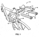
- Figure 1 is a partial front perspective view of a bicycle equipped with a pair of bicycle control (brake/shift) devices coupled to free ends of a bull horn handlebar and a pair of additional attachment bars with electrical shift control devices mounted to their free ends of the attachment bars in accordance with a preferred embodiment of the present invention
- FIG 2 is an enlarged side elevational view of one of the bicycle control (brake/shift) devices attached to one of the free ends of the bull horn handlebar illustrated in Figure 1 in accordance with the present invention
- Figure 3 is an enlarged side elevational view of one of the bicycle control (brake/shift) devices prior to attachment to one of the free ends of the bull horn handlebar illustrated in Figures 1 and 2 in accordance with the present invention;
- Figure 4 is a front end elevational view of one of the bicycle control (brake/shift) devices illustrated in Figures 1-3 in accordance with the present invention
- Figure 5 is a rear end elevational view of one of the bicycle control (brake/shift) devices illustrated in Figures 1-4 in accordance with the present invention
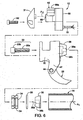
- FIG. 6 is an exploded side elevational view of one of the bicycle control (brake/shift) devices illustrated in Figures 1-5 in accordance with the present invention
- Figure 7 is a partially exploded longitudinal cross-sectional view of one of the bicycle control (brake/shift) devices illustrated in Figures 1-6 , prior to coupling bicycle control (brake/shift) device to the end portion of the handlebar;
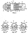
- Figure 8 is a longitudinal cross-sectional view of one of the bicycle control (brake/shift) devices illustrated in Figures 1-7 , after being coupled to the free end of the handlebar;
- Figure 9 is a simplified, partial transverse cross-sectional view of one of the bicycle control (brake/shift) devices illustrated in Figures 1-8 , with the operating member in the neutral position;
- Figure 10 is a simplified, partial transverse cross-sectional view of one of the bicycle control (brake/shift) devices illustrated in Figures 1-8 , with the operating member in first actuating position;
- Figure 11 is a simplified, partial transverse cross-sectional view of one of the bicycle control (brake/shift) devices illustrated in Figures 1-8 , with the operating member in a second actuating position; and
- Figure 12 is a partial front perspective view of the bicycle illustrated in Figure 1 , but equipped with the bicycle control (brake/shift) devices coupled to the additional attachment bars.
- a bicycle 10 is illustrated with a pair of electrical shift/brake control devices 12 coupled to free ends of a bull horn handlebar 14 in accordance with the present invention.
- the bull horn handlebar 14 is also equipped with a pair of additional attachment bars 16 with each of the free ends of the attachment bars 16 having an electrical shift control device 18 mounted thereto.
- the electrical shift/brake control devices 12 and the additional electrical shift control devices 18 form parts of a brake and shift control system of the bicycle 10 in accordance with the present invention.
- the electrical shift/brake control devices 12 can be coupled to free ends each of the free ends of the attachment bars 16 in accordance with the present invention.
- the electrical shift/brake control devices 12 are essentially identical in construction and operation.
- the electrical shift control devices 18 are also essentially identical in construction and operation to the electrical shift/brake control devices 12, except that the braking aspect of the electrical shift/brake control devices 12 as has been eliminated from the electrical shift control devices 18.
- One the electrical shift/brake control devices 12 and one of the electrical shift control devices 18 are operatively coupled to a rear derailleur (not shown) via a cycle computer (not shown), the other ones of the electrical shift/brake control devices 12 and the electrical shift control devices 18 are operatively coupled to a front derailleur (not shown) via the cycle computer (not shown).
- electrical cords 19 electrically couple the electrical shift/brake control devices 12 and the electrical shift control devices 18 to the cycle computer (not shown).
- one of the electrical shift/brake control devices 12 is preferably mechanically coupled directly to one of the braking devices 20 (only one shown in Figure 1 ) via a brake cable 22.
- each of the electrical shift/brake control devices 12 mainly includes a base member 24, an electrical shift control switch 26 and a brake lever 28.
- the base member 24 is mounted within one of the free ends of the handlebar 14 such that the electrical shift control switch 26 faces upwardly and the brake lever 28 extends downwardly and generally parallel to a main center longitudinal axis A 1 of the handlebar 14.
- the electrical cords 19 and the brake cables 22 extend along outer surfaces of handlebar 14 and/or the attachment bars 16, and are preferably covered by handlebar tape as seen in Figure 2 .
- the base member 24 basically has a main body member 30, a cap member 31 coupled to the main body member 30 by a pair of fasteners or screws 32, a fixing bolt 33, a plurality of expansion members 34 coupled together by an elastic ring member 35 and a fixing nut 36.
- the base member 24 is configured to house the electrical shift control switch 26 and pivotally support the brake lever 28.
- the main body member 30 has a stationary projection 38 that is sized to be received inside the free end of the handlebar 14.
- the base member 24 has a handlebar mounting portion that is formed by the fixing bolt 33, the expansion members 34, the elastic ring member 35, the fixing nut 36 and the stationary projection 38.
- these parts 33-38 of the handlebar mounting portion are configured and arranged to fixedly mount to the main body member 30 to the free end of the handlebar 14 as seen in Figure 8 .
- the main body member 30 has a hollow interior 40 for housing the electrical shift control switch 26 and a pair of flanges 42 for pivotally supporting the brake lever 28 via a pivot pin 44.
- the cord 19 and the cable 22 extend into the main body member 30 through openings 46 and 48, respectively, as best seen in Figure 5 .
- the hollow interior 40 of the main body member 30 constitutes an electrical switch housing portion of the base member 24, while the flanges 42 constitute a brake lever mounting portion of the base member 24.
- the brake lever 28 is pivotally attached to the flanges 42 of the base member 24 to be selectively moved relative to the base member 24 between a rest position and a braking position.
- the electrical switch housing portion and the brake lever mounting portion of the main body member 30 is integrally formed together as a one-piece, unitary member from a lightweight, rigid material such as cast aluminum.
- the electrical shift control switch 26 extends longitudinally from the handlebar mounting portion such that main center longitudinal axis A 1 of the free end of the handlebar 14 extends longitudinally through the electrical shift control switch 26.
- the electrical shift control switch 26 can be removed from the main body member 30 without detaching the main body member 30 from the handlebar 14.
- the handlebar mounting portion is basically an expandable unit that is slidable within the free end of the handlebar 14 in a first (unexpanded) configuration and non-slidable within the free end of the handlebar 14 in a second (expanded) configuration, as best seen in Figure 8 .
- the expansion members 34 and the elastic ring member 35 form an expansion structure of the expandable unit that is configured and arranged to be slidable within the free end of the handlebar 14 to fix the base member 24 is mounted to the free end of the handlebar 14.
- the elastic ring member 35 is a resilient element that engages the outer peripheral surfaces of the expansion members 34, which are arranged in a circular pattern.
- the expansion members 34 cooperate with the outer conical surfaces of the fixing nut 36 and the stationary projection 38 such that the expansion members 34 move in a radial direction when the fixing nut 36 is moved axially by the fixing bolt 33 to selectively retain and release the base member 24 within the free end of the handlebar 14.
- the fixing nut 36 acts as axially movable member that moves axially towards the stationary projection 38 in response to rotational movement of the fixing bolt 33 that is threaded into the fixing nut 36 to expand an outer diameter of outer peripheral surfaces of the expansion members 34 against the elastic force of the elastic ring member 35.
- the fixing bolt 33 is a fixing member that is preferably a conventional bolt having a threaded shaft 33a and an enlarged head 33b with a hexagonal bore.
- the fixing bolt 33 extends through a stepped bore 38a of the stationary projection 38.
- the fixing nut 36 is preferably a circular shaped member as viewed in an axial direction.
- the fixing nut 36 includes a threaded bore 36a and a wedge surface 36b.
- the threaded bore 36a threadedly receives the threaded shaft 33a such that rotation of the fixing member or bolt 33 axially moves the fixing nut 36.
- the wedge surface 36b is a frustoconical surface configured to cooperate with the expansion members 36.
- the expansion members 34 are preferably curved, arc-shaped members that are circumferentially arranged about a longitudinal axis of the fixing bolt 33 to move radially outwardly upon axially moving the fixing nut 36.
- the expandable unit includes three of the expansion members 34.
- Each of the expansion members 34 includes a pair of opposed, arc-shaped inclined surfaces 34a and 34b, and an outer groove 34c.
- the arc shaped inclined surfaces 34a of the expansion members 34 form a substantially frustoconically shaped wedge surface of the expansion structure, while arc shaped inclined surfaces 34b of the expansion members 34 form another substantially frustoconically shaped wedge surface of the expansion structure.
- the arc shaped inclined surfaces 34a contact the stationary projection 38, while the arc-shaped inclined surfaces 34b contact the wedge surface 36b of the fixing nut 36.
- the stationary projection 38 is preferable a circular shaped member as viewed axially with a wedge surface 38b.
- the wedge surface 38b is preferably a frustoconical surface substantially identical to the wedge surface 36b.
- the arc shaped inclined surfaces 34a of the expansion members 34 contact the wedge surface 38b of the stationary projection 38.
- the elastic ring member 35 is preferably a continuous annular O-ring that is constructed of a resilient material such as rubber.
- the elastic ring member 35 extends around the expansion members 34 to retain the expansion members 34 together with the fixing bolt 33 and the fixing nut 36. Specifically, the elastic ring member 35 is received in the grooves 34c of the expansion members 34 so the expansion members 34 do not become accidentally misplaced during assembly.
- the electrical shift control switch 26 is mounted to the base member 24 as mentioned above. Basically, the electrical shift control switch 26 is electrically coupled to the electrical cord 19 having one or more electrical conductors.
- the electrical shift control switch 26 basically includes a housing 60, an operating member 62 and an electrical contact assembly 64.
- the precise structure of the electrical shift control switch 26 is not important to the understanding of the present invention and can be construction in a variety of ways to carry out the present invention.
- the operating member 62 is configured and arranged to pivot about an operating axis A 2 that is parallel to the center axis A 1 of the free end of the handlebar 14 when the base member 24 is mounted to the free end of the handlebar 14.
- the operating member 62 is preferably moved relative to the base member 24 between a neutral position and a pair of actuating positions as seen in Figure 9-11 .
- the operating member 62 is disposed on an opposite side of the base member 24 from the brake lever 28.
- the operating member 62 has a curved operating surface with a curvature substantially corresponding to a curvature of the free end of the handlebar 14.
- the operating member 62 basically has an actuator 66, a pivot shaft 68 and a toggle member 70.
- the operating member 62 is pivotally coupled to the housing 60 and operatively coupled to the electrical contact assembly 64 to be selectively moved relative to the base member 24 (i.e., to first and second actuating positions from a neutral, rest position).
- the electrical contact assembly 64 is mounted within the housing 60 and is configured and arranged to be operated by the operating member 62.
- the electrical shift control switch 26 i.e., the operating member 62
- the first and second actuating positions ( Figures 10 and 11 ) are arranged on opposite sides of the neutral position ( Figure 9 ).
- the upshifting and downshifting positions of the operating member 62 could be reversed if needed and/or desired, depending on how the electrical cord 19 is connected.
- the actuator 66 is fixedly attached the outer end of the pivot shaft 68 by a set pin that contacts a flat portion of the outer end of the pivot shaft 68.
- the inner end of the pivot shaft 68 has the toggle member 70 fixedly coupled thereto.
- a biasing element (coil spring) 72 is positioned between the housing 60 and the toggle member 70 to normally bias the toggle member 70, and thus, the operating member 62 to the normal rest or neutral position.
- one end of the spring 72 is preferably received in an axial hole (not shown) of the housing 60, while the other end of the spring 72 is preferably received in an axial hole (not shown) of the toggle member 70.
- the axial holes (not shown) and the spring 72 are preferably arranged and configured to bias the operating member 62 to the neutral rest position from the first and second actuating positions.
- the actuator 66 basically includes a curved operating section 66a that is textured.
- the curved operating section 66a preferably includes a plurality of axially extending grooves to facilitate engagement with the rider's thumb, fingers or hand.
- the curved operating section 66a is a rider actuating section.
- the operating section 66a has an overall curvature substantially corresponding to the curvature of the free end F of the handlebar 14 relative to the rotational axis A 2 and the center axis A 1 .
- the brake lever 28 is pivotally attached to the base member 24 by the pivot pin 44 to be selectively moved relative to the base member 24 between a rest position and a braking position.
- the brake lever 28 is pivotally attached to the flanges 42 of the base member 24.
- the brake lever 28 is disposed on an opposite side of the base member 24 from the operating member 62.
- the upper end of the brake lever 28 has a cable attachment structure 74 that is disposed between the flanges 42 and arranged such that the brake cable 22 extends generally parallel to the center axis A 1 of the free end of the handlebar 14 from the cable attachment structure 74.
Landscapes
- Engineering & Computer Science (AREA)
- Mechanical Engineering (AREA)
- Chemical & Material Sciences (AREA)
- Combustion & Propulsion (AREA)
- Transportation (AREA)
- Steering Devices For Bicycles And Motorcycles (AREA)
- Mechanical Control Devices (AREA)
Claims (8)
- Fahrradsteuervorrichtung (12), umfassend:ein Basiselement (24), enthaltend einen Lenkstangenmontageabschnitt (33, 34, 35, 36, 38), konfiguriert um fest montiert zu werden innen an einem freien Ende einer Lenkstange (14), sowie ein elektrischen Schaltgehäuseabschnitt, sich in Längsrichtung erstreckend von dem Lenkstangenmontageabschnitt (33, 34, 35, 36, 38), derart, dass eine Mittelachse (A1) des freien Endes der Lenkstange (14) sich in Längsrichtung durch den elektrischen Schaltergehäuseabschnitt erstreckt, wenn das Basiselement (24) an dem freien Ende der Lenkstange (14) montiert ist;einen elektrischen Schaltsteuerschalter (26), montiert an den elektrischen Schaltgehäuseabschnitt des Basiselementes (24);eine elektrische Leitung (19) zum elektrischen Koppeln der Steuervorrichtung (12) an einen Fahrradcomputer,dadurch gekennzeichnet, dassdie Fahrradsteuervorrichtung einen Bremshebel (28) enthält, schwenkbar befestigt an dem Basiselement (24) um selektiv bewegt zu werden relativ zu dem Basiselement zwischen einer Ruheposition und einer Bremsposition wobei das obere Ende des Bremshebels (28) eine Bremskabelbefestigungsstruktur (74) enthält, angeordnet zwischen Flanschen und derart vorgesehen, dass sich ein Bremskabel (22) generell parallel zur Mittelachse (A1) erstreckt, wobei sowohl die elektrische Leitung (19) als auch das Bremskabel (22) sich entlang einer Außenfläche der Lenkstange an der unteren Seite der Lenkstange erstrecken, wenn die Vorrichtung an der Lenkstange operativ befestigt ist.
- Fahrradsteuervorrichtung (12) gemäß Anspruch 1, bei welcher der elektrische Schaltsteuerschalter (26) über ein Bedienelement (62) verfügt, welches an einer gegenüberliegenden Seite des Basiselementes (24) bezüglich des Bremshebels (28) angeordnet ist.
- Fahrradsteuervorrichtung gemäß Anspruch 1 oder 2, bei welcher der Lenkstangenmontageabschnitt (33, 34, 35, 36, 38) über eine expandierbare Einheit (34) verfügt, welche konfiguriert und vorgesehen ist um gleitfähig zu sein innerhalb des freien Endes der Lenkstange (14) zum Festlegen des Basiselementes (24) wenn an dem freien Ende der Lenkstange montiert.
- Fahrradsteuervorrichtung gemäß einem der Ansprüche 1 bis 3, bei welcher der elektrische Schaltsteuerschalter (26) über ein Bedienelement (62) verfügt, konfiguriert und vorgesehen zum Schwenken bezüglich einer operativen Achse (A2) welche parallel zur Mittelachse (A1) des freien Endes der Lenkstange (14) ist, wenn das Basiselement (24) an dem freien Ende der Lenkstange montiert ist.
- Fahrradsteuervorrichtung gemäß einem der Ansprüche 1 bis 4, bei welcher das Bedien- oder Betätigungs- oder operative Element (62) über eine gekrümmte Bedienfläche verfügt mit einer Krümmung, im Wesentlichen entsprechend einer Krümmung des freien Endes der Lenkstange (14).
- Fahrradsteuervorrichtung gemäß einem der Ansprüche 1 bis 5, bei welcher der Bremshebel (28) an einer gegenüberliegenden Seite des Basiselementes (24) bezüglich des Bedienelementes (62) angeordnet ist.
- Fahrradsteuervorrichtung gemäß einem der Ansprüche 1 bis 6, bei welcher der Bremshebel (28) schwenkbar befestigt ist an dem Lenkstangenmontageabschnitt (33, 34, 35, 36, 38) des Basiselementes (24) vermittels eines Paares an Flanschen (42).
- Fahrradsteuervorrichtung gemäß Anspruch 7, bei welcher der Bremshebel (28) über eine Kabelbefestigungsstruktur (74) verfügt, welche angeordnet ist zwischen den Flanschen (42) und derart vorgesehen ist, dass sich ein Bremskabel (22) generell parallel zu der Mittelachse (A1) des freien Endes der Lenkstange (14) von der Kabelbefestigungsstruktur (74) erstreckt.
Applications Claiming Priority (1)
| Application Number | Priority Date | Filing Date | Title |
|---|---|---|---|
| US11/331,015 US7565848B2 (en) | 2006-01-13 | 2006-01-13 | Bicycle control device |
Publications (3)
| Publication Number | Publication Date |
|---|---|
| EP1808367A2 EP1808367A2 (de) | 2007-07-18 |
| EP1808367A3 EP1808367A3 (de) | 2007-12-19 |
| EP1808367B1 true EP1808367B1 (de) | 2011-12-21 |
Family
ID=37983409
Family Applications (1)
| Application Number | Title | Priority Date | Filing Date |
|---|---|---|---|
| EP06022721A Active EP1808367B1 (de) | 2006-01-13 | 2006-10-31 | Fahrradsteuerungsvorrichtung |
Country Status (5)
| Country | Link |
|---|---|
| US (1) | US7565848B2 (de) |
| EP (1) | EP1808367B1 (de) |
| JP (1) | JP2007186191A (de) |
| CN (1) | CN100999244A (de) |
| TW (1) | TWI304035B (de) |
Families Citing this family (48)
| Publication number | Priority date | Publication date | Assignee | Title |
|---|---|---|---|---|
| US9446813B2 (en) * | 2006-03-23 | 2016-09-20 | Sram, Llc | Bicycle shifter |
| US8137223B2 (en) * | 2007-05-16 | 2012-03-20 | Shimano Inc. | Bicycle rear derailleur |
| JP4135161B2 (ja) * | 2007-07-14 | 2008-08-20 | 公二 宇野 | 自転車用ブレーキ操作装置 |
| CN101376416B (zh) * | 2007-08-30 | 2014-12-17 | 合成科技有限公司 | 休息把组件 |
| US8056439B2 (en) * | 2007-11-06 | 2011-11-15 | Shimano Inc. | Device to mount control lever to bicycle |
| US20090188340A1 (en) * | 2008-01-24 | 2009-07-30 | Shimano Inc. | Bicycle control device |
| US7908940B2 (en) * | 2008-03-24 | 2011-03-22 | Shimano Inc. | Bar end electric shifter |
| EP2432672A4 (de) * | 2009-05-19 | 2013-01-16 | Ev Ip Llc | Verfahren und vorrichtung zur verwendung elektrisch gesteuerter fahrzeuge |
| US8297143B2 (en) * | 2009-05-19 | 2012-10-30 | Shimano Inc. | Electrical bicycle shift control device |
| US9394031B2 (en) * | 2009-07-16 | 2016-07-19 | Shimano Inc. | Bar end electric shifter for bicycle |
| US8863912B2 (en) * | 2009-08-05 | 2014-10-21 | Shimano Inc. | Brake control apparatus and control lever therefor |
| EP2460716B1 (de) * | 2010-12-03 | 2014-05-07 | Campagnolo S.r.l. | Schalthebel und Betätigungsvorrichtung einer Fahrradgangschaltung des Lenkerendetyps |
| US10207772B2 (en) | 2011-01-28 | 2019-02-19 | Paha Designs, Llc | Gear transmission and derailleur system |
| US9033833B2 (en) | 2011-01-28 | 2015-05-19 | Paha Designs, Llc | Gear transmission and derailleur system |
| US9327792B2 (en) | 2011-01-28 | 2016-05-03 | Paha Designs, Llc | Gear transmission and derailleur system |
| US8453534B2 (en) * | 2011-03-24 | 2013-06-04 | Szu-Fang Tsai | Braking handlebar for bicycle |
| DE102011078480A1 (de) * | 2011-06-30 | 2013-01-03 | Gustav Magenwirth Gmbh & Co. Kg | Geber für ein hydraulisches Betätigungselement |
| EP2562070B1 (de) * | 2011-08-26 | 2015-02-18 | Campagnolo S.r.l. | Fahrradschaltvorrichtung am Lenkerende |
| US10239581B2 (en) * | 2011-08-26 | 2019-03-26 | Gevenalle, Inc | Bicycle brake and shift lever assembly |
| ES2536323T3 (es) * | 2012-04-23 | 2015-05-22 | Campagnolo S.R.L. | Dispositivo de accionamiento eléctrico de cuerno de manillar de un cambio de marchas de bicicleta |
| US9630677B2 (en) * | 2012-06-15 | 2017-04-25 | Sram, Llc | Brake control apparatus |
| US20140083826A1 (en) * | 2012-09-26 | 2014-03-27 | Lee H. Greenberg | Bicycle Bell Using Brake Lever |
| TW201427863A (zh) * | 2013-01-10 | 2014-07-16 | Ad Ii Engineering Inc | 電子變速控制裝置及使用該裝置之自行車握把 |
| CN103963916B (zh) * | 2013-01-24 | 2017-09-29 | 台湾微转股份有限公司 | 电子变速控制装置及使用该装置的自行车握把 |
| US9594393B2 (en) | 2013-01-31 | 2017-03-14 | Shimano Inc. | Bicycle operating device |
| ITMI20130193A1 (it) * | 2013-02-12 | 2014-08-13 | Campagnolo Srl | Metodo per controllare elettronicamente un cambio di bicicletta e cambio di bicicletta servoassistito elettronicamente |
| WO2015039127A1 (en) * | 2013-09-16 | 2015-03-19 | Recreation Systems, Inc. | Handle assembly and associated components for a cycle |
| US20150145230A1 (en) * | 2013-11-26 | 2015-05-28 | BikeStreet USA | Bicycle brake system |
| EP2921395B1 (de) * | 2014-03-18 | 2018-01-17 | Askoll Eva S.R.L. | Bremsbetätigungseinrichtung für elektrische Fahrräder |
| US9896150B2 (en) * | 2015-01-30 | 2018-02-20 | Shimano Inc. | Bicycle operating device |
| US10550858B2 (en) * | 2014-08-25 | 2020-02-04 | Shimano Inc. | Bicycle control device |
| US10189531B2 (en) | 2015-05-08 | 2019-01-29 | Shimano Inc. | Bicycle operating device |
| US9821884B2 (en) | 2015-05-29 | 2017-11-21 | Shimano Inc. | Bicycle operating device |
| US10279867B2 (en) | 2015-05-29 | 2019-05-07 | Shimano Inc. | Bicycle operating device |
| JP2018001883A (ja) * | 2016-06-28 | 2018-01-11 | 株式会社シマノ | 自転車用バーエンド |
| US20180057093A1 (en) * | 2016-08-24 | 2018-03-01 | Todd N. Lenig | Handlebar mounted tool system and method of use |
| US10384741B2 (en) * | 2016-09-30 | 2019-08-20 | Shimano Inc. | Bicycle hydraulic operating device |
| US10167041B2 (en) * | 2016-11-01 | 2019-01-01 | Shimano Inc. | Bicycle operating device |
| US10882580B2 (en) * | 2016-11-01 | 2021-01-05 | Shimano Inc. | Bicycle component mounting device |
| US10583890B2 (en) * | 2017-02-21 | 2020-03-10 | Shimano Inc. | Bar-end device assembly for tube member of bicycle |
| US10093383B1 (en) | 2017-03-23 | 2018-10-09 | Shimano Inc. | Bicycle operating device |
| CN110914143A (zh) * | 2017-06-23 | 2020-03-24 | 优步技术公司 | 电动助力自行车 |
| USD844928S1 (en) * | 2017-07-25 | 2019-04-02 | Cambro Manufacturing Company | Dish caddy adjusting lever |
| US10759495B2 (en) * | 2018-01-12 | 2020-09-01 | Tien Hsin Industries Co., Ltd. | Integrated control device and integrated handlebar for bicycle |
| JP6968742B2 (ja) * | 2018-03-30 | 2021-11-17 | 株式会社シマノ | 制御装置およびコンポーネントシステム |
| US10569717B2 (en) * | 2018-05-31 | 2020-02-25 | Annex Products Pty. Ltd. | Mount for handheld electronic devices |
| CN111762278B (zh) * | 2019-03-28 | 2021-12-28 | 台湾微转股份有限公司 | 电动自行车操作装置 |
| NO345470B1 (en) | 2019-07-08 | 2021-02-15 | Bikefinder As | Device for fixing equipment to an end of the inner surface of a tube |
Family Cites Families (27)
| Publication number | Priority date | Publication date | Assignee | Title |
|---|---|---|---|---|
| US4143557A (en) | 1977-04-18 | 1979-03-13 | Sanyo Electric Co., Ltd | Control system for use in a multiple speed transmission system |
| JPS56129388U (de) * | 1980-03-03 | 1981-10-01 | ||
| JPS56132192U (de) * | 1980-03-10 | 1981-10-07 | ||
| US4548092A (en) * | 1983-02-10 | 1985-10-22 | Strong Jr Samuel Z | Bicycle gear shift unit |
| JPS62161097U (de) * | 1986-03-31 | 1987-10-13 | ||
| US4900291B1 (en) | 1988-01-06 | 2000-04-25 | Sram Corp | Bicycle gear shifting method and apparatus |
| FR2687977B1 (fr) | 1992-02-27 | 1994-04-22 | Bg Innovation | Dispositifs permettant les changements de vitesses sur bicyclettes. |
| IT1261090B (it) | 1993-07-08 | 1996-05-08 | Antonio Romano | Gruppo di cambio di velocita' motorizzato per biciclette. |
| DE4420125C2 (de) | 1993-07-29 | 1996-01-25 | Fichtel & Sachs Ag | Drehgriffschalter für Fahrräder |
| JP3470820B2 (ja) | 1993-10-06 | 2003-11-25 | 株式会社シマノ | 自転車用変速装置 |
| JPH0826174A (ja) * | 1994-07-15 | 1996-01-30 | Yamaha Motor Co Ltd | 自転車の多段変速装置 |
| DE29507555U1 (de) | 1995-05-05 | 1995-07-13 | Chia, Tung-Chung, Ching Shui, Taichung | Einrichtung für Bremsenbetätigung und Gangwechsel für ein Fahrrad |
| US5775168A (en) | 1996-02-14 | 1998-07-07 | Shimano, Inc. | Combined brake and shifting device |
| US5768945A (en) | 1996-02-14 | 1998-06-23 | Shimano, Inc. | Extension handle for a bicycle shifting device |
| US5678455A (en) | 1996-02-15 | 1997-10-21 | Shimano, Inc. | Bar-end shifting device |
| JP3279203B2 (ja) * | 1996-11-19 | 2002-04-30 | 株式会社シマノ | 自転車用ブレーキレバー及びバーエンド |
| JP3128116B2 (ja) | 1996-12-19 | 2001-01-29 | 株式会社シマノ | 自転車用切換スイッチ |
| JP3474080B2 (ja) | 1997-05-16 | 2003-12-08 | 株式会社シマノ | 自転車用スイッチ |
| US5950498A (en) * | 1997-08-07 | 1999-09-14 | Gossett; J. Cary | Handle storage apparatus and method |
| US6038923A (en) | 1998-05-27 | 2000-03-21 | Giant Manufacturing Co., Ltd. | Hand-operated accelerator device for an electric-powered bicycle |
| DE19837163C1 (de) * | 1998-08-17 | 2000-03-16 | Deere & Co | Handbedienungshebel |
| DE10055922A1 (de) | 2000-11-10 | 2002-05-23 | Sram De Gmbh | Kombinierte Schalt- und Bremsvorrichtung |
| US6546827B2 (en) | 2001-03-28 | 2003-04-15 | Shimano Inc. | Bicycle handlebar |
| US6698307B2 (en) | 2001-10-23 | 2004-03-02 | Sram Corporation | Electronic shifter for a bicycle |
| US7228756B2 (en) | 2003-11-25 | 2007-06-12 | Shimano Inc. | Bicycle control device |
| US6991081B2 (en) | 2003-11-26 | 2006-01-31 | Shimano Inc. | Shift and break control device |
| US7350436B2 (en) | 2004-03-29 | 2008-04-01 | Shimano, Inc. | Electrical bicycle shift control device |
-
2006
- 2006-01-13 US US11/331,015 patent/US7565848B2/en active Active
- 2006-08-15 TW TW095129932A patent/TWI304035B/zh active
- 2006-10-31 EP EP06022721A patent/EP1808367B1/de active Active
- 2006-12-04 JP JP2006327414A patent/JP2007186191A/ja active Pending
-
2007
- 2007-01-12 CN CNA2007100021991A patent/CN100999244A/zh active Pending
Also Published As
| Publication number | Publication date |
|---|---|
| CN100999244A (zh) | 2007-07-18 |
| US20070175290A1 (en) | 2007-08-02 |
| US7565848B2 (en) | 2009-07-28 |
| JP2007186191A (ja) | 2007-07-26 |
| TWI304035B (en) | 2008-12-11 |
| TW200726693A (en) | 2007-07-16 |
| EP1808367A2 (de) | 2007-07-18 |
| EP1808367A3 (de) | 2007-12-19 |
Similar Documents
| Publication | Publication Date | Title |
|---|---|---|
| EP1808367B1 (de) | Fahrradsteuerungsvorrichtung | |
| US7908940B2 (en) | Bar end electric shifter | |
| US7350436B2 (en) | Electrical bicycle shift control device | |
| JP4122012B2 (ja) | 自転車用電気シフト制御装置 | |
| EP2275338B1 (de) | Elektroschalter am Stangenende für Fahrräder | |
| EP2196385B1 (de) | Fahrradbetätigungsvorrichtung | |
| US7942250B2 (en) | Bicycle hydraulic brake device | |
| US8777788B2 (en) | Bicycle component positioning device | |
| EP1816062B1 (de) | Steuerungseinrichtung für eine Fahrradgangschaltung | |
| US10189531B2 (en) | Bicycle operating device | |
| US10137957B2 (en) | Bicycle operating device | |
| EP1935770B1 (de) | Montagestruktur für Fahrradteile |
Legal Events
| Date | Code | Title | Description |
|---|---|---|---|
| PUAI | Public reference made under article 153(3) epc to a published international application that has entered the european phase |
Free format text: ORIGINAL CODE: 0009012 |
|
| AK | Designated contracting states |
Kind code of ref document: A2 Designated state(s): AT BE BG CH CY CZ DE DK EE ES FI FR GB GR HU IE IS IT LI LT LU LV MC NL PL PT RO SE SI SK TR |
|
| AX | Request for extension of the european patent |
Extension state: AL BA HR MK YU |
|
| PUAL | Search report despatched |
Free format text: ORIGINAL CODE: 0009013 |
|
| AK | Designated contracting states |
Kind code of ref document: A3 Designated state(s): AT BE BG CH CY CZ DE DK EE ES FI FR GB GR HU IE IS IT LI LT LU LV MC NL PL PT RO SE SI SK TR |
|
| AX | Request for extension of the european patent |
Extension state: AL BA HR MK YU |
|
| 17P | Request for examination filed |
Effective date: 20080222 |
|
| AKX | Designation fees paid |
Designated state(s): DE FR IT NL |
|
| 17Q | First examination report despatched |
Effective date: 20081113 |
|
| GRAP | Despatch of communication of intention to grant a patent |
Free format text: ORIGINAL CODE: EPIDOSNIGR1 |
|
| GRAS | Grant fee paid |
Free format text: ORIGINAL CODE: EPIDOSNIGR3 |
|
| GRAA | (expected) grant |
Free format text: ORIGINAL CODE: 0009210 |
|
| AK | Designated contracting states |
Kind code of ref document: B1 Designated state(s): DE FR IT NL |
|
| REG | Reference to a national code |
Ref country code: DE Ref legal event code: R096 Ref document number: 602006026468 Country of ref document: DE Effective date: 20120322 |
|
| REG | Reference to a national code |
Ref country code: NL Ref legal event code: T3 |
|
| PLBE | No opposition filed within time limit |
Free format text: ORIGINAL CODE: 0009261 |
|
| STAA | Information on the status of an ep patent application or granted ep patent |
Free format text: STATUS: NO OPPOSITION FILED WITHIN TIME LIMIT |
|
| 26N | No opposition filed |
Effective date: 20120924 |
|
| REG | Reference to a national code |
Ref country code: DE Ref legal event code: R097 Ref document number: 602006026468 Country of ref document: DE Effective date: 20120924 |
|
| PGFP | Annual fee paid to national office [announced via postgrant information from national office to epo] |
Ref country code: IT Payment date: 20121024 Year of fee payment: 7 |
|
| PGFP | Annual fee paid to national office [announced via postgrant information from national office to epo] |
Ref country code: NL Payment date: 20121018 Year of fee payment: 7 |
|
| REG | Reference to a national code |
Ref country code: NL Ref legal event code: V1 Effective date: 20140501 |
|
| PG25 | Lapsed in a contracting state [announced via postgrant information from national office to epo] |
Ref country code: IT Free format text: LAPSE BECAUSE OF NON-PAYMENT OF DUE FEES Effective date: 20131031 Ref country code: NL Free format text: LAPSE BECAUSE OF NON-PAYMENT OF DUE FEES Effective date: 20140501 |
|
| PGFP | Annual fee paid to national office [announced via postgrant information from national office to epo] |
Ref country code: FR Payment date: 20141008 Year of fee payment: 9 |
|
| REG | Reference to a national code |
Ref country code: FR Ref legal event code: ST Effective date: 20160630 |
|
| PG25 | Lapsed in a contracting state [announced via postgrant information from national office to epo] |
Ref country code: FR Free format text: LAPSE BECAUSE OF NON-PAYMENT OF DUE FEES Effective date: 20151102 |
|
| REG | Reference to a national code |
Ref country code: DE Ref legal event code: R082 Ref document number: 602006026468 Country of ref document: DE Representative=s name: SONNENBERG HARRISON PARTNERSCHAFT MBB, DE Ref country code: DE Ref legal event code: R082 Ref document number: 602006026468 Country of ref document: DE Representative=s name: SONNENBERG HARRISON PARTNERSCHAFT MBB PATENT- , DE |
|
| P01 | Opt-out of the competence of the unified patent court (upc) registered |
Effective date: 20230421 |
|
| PGFP | Annual fee paid to national office [announced via postgrant information from national office to epo] |
Ref country code: DE Payment date: 20230906 Year of fee payment: 18 |