EP2196385B1 - Fahrradbetätigungsvorrichtung - Google Patents
Fahrradbetätigungsvorrichtung Download PDFInfo
- Publication number
- EP2196385B1 EP2196385B1 EP09009721A EP09009721A EP2196385B1 EP 2196385 B1 EP2196385 B1 EP 2196385B1 EP 09009721 A EP09009721 A EP 09009721A EP 09009721 A EP09009721 A EP 09009721A EP 2196385 B1 EP2196385 B1 EP 2196385B1
- Authority
- EP
- European Patent Office
- Prior art keywords
- operating unit
- attachment portion
- band part
- clamp portion
- connecting member
- Prior art date
- Legal status (The legal status is an assumption and is not a legal conclusion. Google has not performed a legal analysis and makes no representation as to the accuracy of the status listed.)
- Revoked
Links
- 238000004804 winding Methods 0.000 description 5
- 239000000463 material Substances 0.000 description 4
- 230000008878 coupling Effects 0.000 description 2
- 238000010168 coupling process Methods 0.000 description 2
- 238000005859 coupling reaction Methods 0.000 description 2
- 239000002184 metal Substances 0.000 description 2
- 230000002860 competitive effect Effects 0.000 description 1
- 230000009977 dual effect Effects 0.000 description 1
- 239000012530 fluid Substances 0.000 description 1
- 230000004048 modification Effects 0.000 description 1
- 238000012986 modification Methods 0.000 description 1
Images


Classifications
-
- B—PERFORMING OPERATIONS; TRANSPORTING
- B62—LAND VEHICLES FOR TRAVELLING OTHERWISE THAN ON RAILS
- B62M—RIDER PROPULSION OF WHEELED VEHICLES OR SLEDGES; POWERED PROPULSION OF SLEDGES OR SINGLE-TRACK CYCLES; TRANSMISSIONS SPECIALLY ADAPTED FOR SUCH VEHICLES
- B62M25/00—Actuators for gearing speed-change mechanisms specially adapted for cycles
- B62M25/02—Actuators for gearing speed-change mechanisms specially adapted for cycles with mechanical transmitting systems, e.g. cables, levers
- B62M25/04—Actuators for gearing speed-change mechanisms specially adapted for cycles with mechanical transmitting systems, e.g. cables, levers hand actuated
-
- B—PERFORMING OPERATIONS; TRANSPORTING
- B60—VEHICLES IN GENERAL
- B60T—VEHICLE BRAKE CONTROL SYSTEMS OR PARTS THEREOF; BRAKE CONTROL SYSTEMS OR PARTS THEREOF, IN GENERAL; ARRANGEMENT OF BRAKING ELEMENTS ON VEHICLES IN GENERAL; PORTABLE DEVICES FOR PREVENTING UNWANTED MOVEMENT OF VEHICLES; VEHICLE MODIFICATIONS TO FACILITATE COOLING OF BRAKES
- B60T7/00—Brake-action initiating means
- B60T7/02—Brake-action initiating means for personal initiation
- B60T7/08—Brake-action initiating means for personal initiation hand actuated
- B60T7/10—Disposition of hand control
- B60T7/102—Disposition of hand control by means of a tilting lever
-
- B—PERFORMING OPERATIONS; TRANSPORTING
- B62—LAND VEHICLES FOR TRAVELLING OTHERWISE THAN ON RAILS
- B62K—CYCLES; CYCLE FRAMES; CYCLE STEERING DEVICES; RIDER-OPERATED TERMINAL CONTROLS SPECIALLY ADAPTED FOR CYCLES; CYCLE AXLE SUSPENSIONS; CYCLE SIDE-CARS, FORECARS, OR THE LIKE
- B62K23/00—Rider-operated controls specially adapted for cycles, i.e. means for initiating control operations, e.g. levers, grips
- B62K23/02—Rider-operated controls specially adapted for cycles, i.e. means for initiating control operations, e.g. levers, grips hand actuated
- B62K23/06—Levers
-
- G—PHYSICS
- G05—CONTROLLING; REGULATING
- G05G—CONTROL DEVICES OR SYSTEMS INSOFAR AS CHARACTERISED BY MECHANICAL FEATURES ONLY
- G05G11/00—Manually-actuated control mechanisms provided with two or more controlling members co-operating with one single controlled member
-
- Y—GENERAL TAGGING OF NEW TECHNOLOGICAL DEVELOPMENTS; GENERAL TAGGING OF CROSS-SECTIONAL TECHNOLOGIES SPANNING OVER SEVERAL SECTIONS OF THE IPC; TECHNICAL SUBJECTS COVERED BY FORMER USPC CROSS-REFERENCE ART COLLECTIONS [XRACs] AND DIGESTS
- Y10—TECHNICAL SUBJECTS COVERED BY FORMER USPC
- Y10T—TECHNICAL SUBJECTS COVERED BY FORMER US CLASSIFICATION
- Y10T74/00—Machine element or mechanism
- Y10T74/20—Control lever and linkage systems
- Y10T74/20207—Multiple controlling elements for single controlled element
- Y10T74/20256—Steering and controls assemblies
- Y10T74/20268—Reciprocating control elements
- Y10T74/2028—Handle bar type
- Y10T74/20287—Flexible control element
-
- Y—GENERAL TAGGING OF NEW TECHNOLOGICAL DEVELOPMENTS; GENERAL TAGGING OF CROSS-SECTIONAL TECHNOLOGIES SPANNING OVER SEVERAL SECTIONS OF THE IPC; TECHNICAL SUBJECTS COVERED BY FORMER USPC CROSS-REFERENCE ART COLLECTIONS [XRACs] AND DIGESTS
- Y10—TECHNICAL SUBJECTS COVERED BY FORMER USPC
- Y10T—TECHNICAL SUBJECTS COVERED BY FORMER US CLASSIFICATION
- Y10T74/00—Machine element or mechanism
- Y10T74/20—Control lever and linkage systems
- Y10T74/20396—Hand operated
- Y10T74/20402—Flexible transmitter [e.g., Bowden cable]
- Y10T74/2042—Flexible transmitter [e.g., Bowden cable] and hand operator
- Y10T74/20438—Single rotatable lever [e.g., for bicycle brake or derailleur]
-
- Y—GENERAL TAGGING OF NEW TECHNOLOGICAL DEVELOPMENTS; GENERAL TAGGING OF CROSS-SECTIONAL TECHNOLOGIES SPANNING OVER SEVERAL SECTIONS OF THE IPC; TECHNICAL SUBJECTS COVERED BY FORMER USPC CROSS-REFERENCE ART COLLECTIONS [XRACs] AND DIGESTS
- Y10—TECHNICAL SUBJECTS COVERED BY FORMER USPC
- Y10T—TECHNICAL SUBJECTS COVERED BY FORMER US CLASSIFICATION
- Y10T74/00—Machine element or mechanism
- Y10T74/20—Control lever and linkage systems
- Y10T74/20576—Elements
- Y10T74/20732—Handles
- Y10T74/2078—Handle bars
- Y10T74/20822—Attachments and accessories
Definitions
- This invention generally relates to a bicycle operating unit connector. More specifically, the present invention relates to a bicycle operating unit connector that connects a first operating unit to a second operating unit in an adjustable manner.
- Bicycling is becoming an increasingly more popular form of recreation as well as a means of transportation. Moreover, bicycling has become a very popular competitive sport for both amateurs and professionals. Whether the bicycle is used for recreation, transportation or competition, the bicycle industry is constantly improving the various components of the bicycle.
- Bicycles are typically provided with a pair of brake levers for operating brake devices that apply braking forces to stop rotation of the wheels.
- These brake levers are typically mounted on the handlebar by a bracket having band clamp, with one being located adjacent each of the grips of the handlebar.
- a shifter or shift operating device is often mounted adjacent each of the brake levers.
- the shift operating device is made to shift the gears by operating an operating member in the form of a lever, for example.
- a conventional shift operating device has a bracket mounted on a handlebar, and a main shifter body mounted on the mounting bracket. In conventional practice, in cases in which a shift operating device is provided separately from a brake lever, normally, the shift operating device is attached to the handlebar inside the bracket of the brake lever. If the shift operating device is attached to the handlebar within the brake lever, then the shifter may be difficult to operate, depending on the shape(s) of the operating member(s) of the shift operating device.
- the brake lever and the shift operating device are integrated together as a single unit.
- the brake lever and the shift operating device are fixed relative to each other (See, for example, U.S Patent No. 5,701,786 , assigned to Shimano Inc).
- combination brake/shift operating devices have been proposed in which the main shifter body is capable of moving in relation to the bracket (i.e., the attachment part) of the brake lever, such that the position of the main shifter body can be varied in an axial direction of the handlebar (See, for example, U.S Patent No. 4,974,469).
- the Japanese Patent Application JP 63 315390 which represents the closest prior art according to the preamble of claim 1 and 13, discloses a bicycle operating device in which a braking lever and a shifting lever are integrated into a single unit.
- the braking lever includes a clamp portion for attaching the lever to the handlebar.
- a connector is provided such that the linear position of the shifting lever can be adjusted with respect to the axial direction of the handlebar.
- the connector also has a portion integrally formed as one piece with a band part of the clamp portion of the braking lever.
- One object of the present invention is to provide a bicycle operating unit connector that connects a first operating unit to a second operating unit in an adjustable manner.
- a bicycle operating device and a bicycle operating unit connector are provided as defined in claims 1 and 13, respectively.
- the bicycle operating unit connector comprises a first attachment portion and a second attachment portion.
- the first attachment portion includes a curved mounting surface with an opening that is detachably attached to an outwardly facing surface of a band part of a clamp portion of a brake operating unit by an adjustable connection for changing a relative position of the connector with respect to the clamp portion of the brake operating unit.
- the second attachment portion extends from the first attachment portion.
- the second attachment portion includes a hole that is configured to be detachably attached to a shift operating unit.
- the bicycle operating device comprises a first operating unit, a second operating unit and a connecting member.
- the first operating unit includes a clamp portion and a first operating member.
- the second operating unit includes a housing and a second operating member.
- the connecting member includes a first attachment portion and a second attachment portion, with the first attachment portion being detachably attached to an outwardly facing surface of the clamp portion by an adjustable connection that is adjustable to change a relative position of the connecting member with respect to the clamp portion.
- the second attachment portion is detachably attached to the second operating unit.
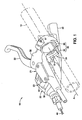
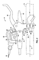
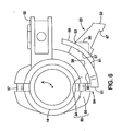
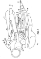
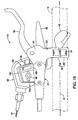
- a bicycle operating device 10 is illustrated in accordance with a first embodiment.
- the bicycle operating device 10 is configured and arranged to be mounted on an end of a handlebar 14.
- the bicycle operating device 10 is provided with a first operating unit 21, a second operating unit 22 and a connecting member 23 that adjustably mounts the second operating unit 22 on the first operating unit 21, as discussed below.
- the first operating unit 21 is a hydraulic brake operating unit
- the second operating unit 22 is a cable operated shift operating unit.
- the first operating unit 21 can be a cable operated brake operating unit or any other type of brake operating unit, as needed and/or desired.
- the second operating unit 22 can be any type of shift operating unit, as needed and/or desired.
- the first and second operating units 21 and 22 will not be discussed and/or illustrated, except to the extent that they are configured to carry other the present invention.
- the first operating unit 21 includes a clamp portion 30, a bracket portion 32 and a lever or first operating member 33.
- the lever 33 is pivotally mounted to the bracket portion 32. Operation of the lever 33 causes an increase in fluid pressure to operate a brake device (not shown) in a conventional manner.
- the clamp portion 30 has a first band part 34 and a second band part 35. The first and second band parts 34 and 35 are connected together by a pair of threaded fasteners or screws 36 and 37. The screw 36 is also used to secure the connecting member 23 to the first band part 34 of the clamp portion 30.
- the first band part 34 is integrally formed with the bracket portion 32.
- the first band part 34 has a non-threaded hole 34a for receiving the screw 36 and a threaded hole 34b for threadedly receiving the screw 37.
- the second band part 35 has a threaded hole 35a for threadedly receiving the screw 36 and a non-threaded hole 35b for receiving the screw 37.
- the first and second band parts 34 and 35 move towards each other to squeeze the handlebar 14.
- the first and second band parts 34 and 35 fixedly secure the first and second operating units 21 and 22 to the handlebar 14.
- a center axis A of the handlebar 14 becomes coincident with a center axis of the clamp portion 30.
- the center axis A as shown in the drawings refers to both the center axis of the handlebar 14 and the center axis of the clamp portion 30.
- the first band part 34 of the clamp portion 30 has an outwardly facing surface 38.
- the outwardly facing surface 38 of the first band part 34 of the clamp portion 30 is convexly curved about the center axis A or an axis that is parallel to the center axis A.
- the outwardly facing surface 38 of the first band part 34 of the clamp portion 30 can be convexly curved about an axis that is non-parallel to the center axis A.
- the outwardly facing surface 38 of the first band part 34 cooperates with the connecting member 23 to provide for adjustment of the connecting member 23 in an angular direction with respect to the clamp portion 30.
- the connecting member 23 can be secured in a plurality of angular orientations (e.g., two of the angular orientations are best seen in Figures 6 and 9 ).
- the second operating unit 22 includes a housing 40, a cable winding unit 41 disposed inside the housing 40 and a pair of operating member 42 and 43 extending out of the housing 40.
- the operating member 42 and 43 are used to operate the cable winding unit 41 to pull and release an inner wire 44 that is attached to a wire takeup member of the cable winding unit 41.
- Shifters are well known in the bicycle field, and it will be apparent from this disclosure that the second operating unit 22 can be any type of shifter unit (e.g., a one lever shifter, a two lever shifter, etc.).
- the cable winding unit 41 can be any type of shifting unit.
- the cable winding unit 41 will not be described and/or illustrated in detail herein.
- the housing 40 has an upper surface with a protruding rib 45 that acts as a positioning member or an anti-rotation member.
- the connecting member 23 is attached to the housing 40 by a threaded fastener or screw 46 that engages a threaded hole of the second operating unit 22.
- the protruding rib 45 engages the connecting member 23 to prevent relative rotation of the second operating unit 22 with respect to the connecting member 23 about the axis of the screw 46.
- the connecting member 23 is an attachment member (adapter) for attaching the second operating (shift lever) unit 22 to the first operating (brake lever) unit 21.
- This connecting member 23 can provide an adjustment function of the second operating (shift lever) unit 22 with respect to the first operating (brake lever) unit 21 in two different directions. In this embodiment, one direction is in parallel with handlebar, and the other direction is around the brake band, but the present invention is not limited to these two specific directions.
- the connecting member 23 is configured and arranged to change a relative position of the second operating unit 22 with respect to the first operating unit 21 or the handlebar 14.
- the relative position of the second operating unit 22 with respect to the first operating unit 21 or the handlebar 14 can be changed both in a linear direction and an angular direction with respect to the center axis A of the handlebar 14 and the clamp portion 30.
- the linear location and the angular orientation of the second operating unit 22 are both independently adjustable with respect to the center axis A of the handlebar 14 where the first operating unit 21 is fixed to the handlebar 14.
- linear direction with respect to a center axis does not require the linear direction to be parallel with respect to the center axis, but rather the linear direction can include both an angular component of movement and a linear component of movement with respect to the center axis as some other component of movement.
- angular direction relative to a center axis does not require the angular direction to concentric with the center axis, but rather the angular direction can include movement that are not concentric with the center axis.
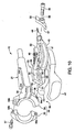
- the connecting member 23 is preferably a one-piece, unitary member that is constructed of a hard rigid material such a rigid metal or a rigid plastic material.
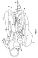
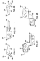
- the connecting member 23 basically includes a first attachment portion 51, a second attachment portion 52 and an intermediate portion 53 interconnecting the first and second attachment portions 51 and 52.
- the first attachment portion 51 is detachably attached to the outwardly facing surface 38 of the first band part 34 of the clamp portion 30 by an adjustable connection 54 that is adjustable to change a relative position of the connecting member 23 with respect to the clamp portion 30.
- the second attachment portion 52 is detachably attached to the second operating unit 22 by the fastener or screw 46.
- the adjustable connection 54 between the first attachment portion 51 of the connecting member 23 and the first band part 34 of the clamp portion 30 provides relative movement of the connecting member 23 with respect to the clamp portion 30 in both the linear direction and the angular direction with respect to the center axis A of the band part (e.g., the first band part 34 and the second band part 35) of the clamp portion 30.
- the adjustable connection 54 is formed by the fastener or screw 36, the threaded hole 35b of the second band part 35, the outwardly facing surface 38 of the first band part 34.
- the first attachment portion 51 is configured to be detachably attached to the outwardly facing surface 38 of the first band part 34 of the clamp portion 30 by the fastener or screw 36.
- a washer 56 is provided between the head of the screw 36 and the first attachment portion 51.
- the washer 56 has a concaved engagement surface 57 that contacts the first attachment portion 51 and a hole 58 for receiving the screw 36.
- the first attachment portion 51 includes a curved mounting surface 60, a curved engagement surface 61 and an adjustment opening 62 that extends between the curved mounting surface 60 and the curved engagement surface 61.
- the curved mounting surface 60 engages or mates with the outwardly facing surface 38 of the first band part 34 of the clamp portion 30 such that the outwardly facing surface 38 and the curved mounting surface 60 cooperate together to form at least part of the adjustable connection 54.
- the curved engagement surface 61 engages or mates with the concaved engagement surface 57 of the washer 56.
- the adjustment opening 62 and the fastener or screw 36 are dimensioned with the fastener or screw 36 having its shaft disposed in the adjustment opening 62 when the connecting member 23 is fastened to the band part (i.e., the first and second band parts 34 and 35) of the clamp portion 30.
- the dimension of the adjustment opening 62 with respect to the dimension (i.e., the diameter or width) of the shaft of the screw 36 disposed in the adjustment opening 62 determines the range of adjustment of the connecting member 23 with respect to the band part (i.e., the first and second band parts 34 and 35) of the clamp portion 30.
- the hole 34a non-threadedly receives a portion of the shaft of the fastener or screw 36 therethrough, while the hole 35a threadedly receives a threaded portion of the shaft of the fastener or screw 36 therein.
- the connecting member 23 can be adjusted by the surfaces 60 and 61 sliding between the surfaces 38 and 57 such that the fastener or screw 36, the adjustment opening 62 and the threaded hole 35b cooperate together to further form at least part of the adjustable connection 54.
- the adjustment opening 62 is a generally rectangular opening that has a width and a length that is larger than a diameter of the screw 36 that extends through the adjustment opening 62 so that the position of the connecting member 23 can be independently adjusted with respect to the first band part 34 of the clamp portion 30 in both the linear direction and the angular direction as mentioned above. In this way, the relative position of the second operating unit 22 with respect to the first operating unit 21 or the handlebar 14 can be changed both in the linear direction and the angular direction with respect to the center axis A of the handlebar 14 and the clamp portion 30.
- the second attachment portion 52 extends transversely from the first attachment portion 51 via the intermediate portion 53.
- the second attachment portion 52 is configured to be detachably attached to the second operating unit 22 by the fastener or screw 46.
- the second attachment portion 52 includes a circular mounting hole 66 that receives the screw 46 to fixedly secure the second attachment portion 52 to the second operating unit 22.
- the lower surface of the second attachment portion 52 has a recess 67 that receives the protruding rib 45 of the housing 40 of the second operating unit 22 to prevent relative rotation therebetween.
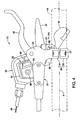
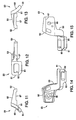
- a bicycle operating device 110 in accordance with a second embodiment will now be explained.
- the bicycle operating device 110 uses a modified connecting member 123.
- the parts of the second embodiment that are identical to the parts of the first embodiment will be given the same reference numerals as the parts of the first embodiment.
- the descriptions of the parts of the second embodiment that are identical to the parts of the first embodiment may be omitted for the sake of brevity.
- the connecting member 123 is configured and arranged to change a relative position of the second operating unit 22 with respect to the first operating unit 21 or the handlebar 14 in both the linear direction and the angular direction with respect to the center axis A of the handlebar 14 and the clamp portion 30.
- the connecting member 123 is preferably a one-piece, unitary member that is constructed of a hard rigid material such a rigid metal or a rigid plastic material.
- the connecting member 123 basically includes a first attachment portion 151, a second attachment portion 152 and an intermediate portion 153 interconnecting the first and second attachment portions 151 and 152.
- the first attachment portion 151 is detachably attached to the outwardly facing surface 38 of the first band part 34 of the clamp portion 30 to change a relative position of the second operating unit 22 with respect to the clamp portion 30.
- the second attachment portion 152 is detachably attached to the second operating unit 22 by the fastener or screw 46.
- the first attachment portion 151 is configured to be detachably attached to the outwardly facing surface 38 of the first band part 34 of the clamp portion 30 by the fastener or screw 36.
- the washer 56 is provided between the head of the screw 36 and the first attachment portion 151.
- the first attachment portion 151 includes a curved mounting surface 160, a curved engagement surface 161 and an adjustment opening 162 that extends between the curved mounting surface 160 and the curved engagement surface 161.
- the adjustment opening 162 is an elongated slot that is arranged to provide adjustment of the second operating unit 22 in the angular direction with respect to the center axis A.
- the connecting member 123 When the connecting member 123 is attached to the clamp portion 30 by the screw 36, the curved mounting surface 160 engages or mates with the outwardly facing surface 38 of the first band part 34 of the clamp portion 30 such that the outwardly facing surface 38 and the curved mounting surface 160 cooperate together.
- the curved engagement surface 161 engages or mates with the concaved engagement surface 157 of the washer 156.
- the second attachment portion 152 extends transversely from the first attachment portion 151 via the intermediate portion 153.
- the second attachment portion 152 is configured to be detachably attached to the second operating unit 22 by the fastener or screw 46.
- the second attachment portion 152 includes an elongated mounting hole 166 that receives the screw 46 to fixedly secure the second attachment portion 52 to the second operating unit 22.
- the lower surface of the second attachment portion 152 has a recess 167 that receives the protruding rib 45 of the housing 40 of the second operating unit 22 to prevent relative rotation therebetween.
- the elongated mounting hole 166 is arranged for adjusting the position of the second operating unit 22 in the linear direction with respect to the center axis A.
- the elongated mounting hole 166 is a slot that is arranged in a linear direction parallel to the center axis A.
- the elongated mounting hole or slot 166 is transversely arranged with respect to the adjustment opening or slot 162.
Landscapes
- Engineering & Computer Science (AREA)
- Mechanical Engineering (AREA)
- Transportation (AREA)
- Physics & Mathematics (AREA)
- General Physics & Mathematics (AREA)
- Automation & Control Theory (AREA)
- Chemical & Material Sciences (AREA)
- Combustion & Propulsion (AREA)
- Steering Devices For Bicycles And Motorcycles (AREA)
- Mechanical Control Devices (AREA)
- Control Of Throttle Valves Provided In The Intake System Or In The Exhaust System (AREA)
- Automatic Cycles, And Cycles In General (AREA)
Claims (15)
- Fahrradbedienungsvorrichtung, aufweisend:eine erste Bedienungseinheit (21) mit einem Schellenabschnitt (30) zum Befestigen der Fahrradbedienungsvorrichtung an einem Fahrrad und mit einem ersten Bedienungselement (33);eine zweite Bedienungseinheit (22) mit einem Gehäuse (40) und einem zweiten Bedienungselement (42); undein Verbindungselement (23) mit einem ersten Befestigungsabschnitt (51) und einem zweiten Befestigungsabschnitt (52),wobei der erste Befestigungsabschnitt (51) über eine Verbindung (54) an einem Bandteil (34) des Schellenabschnittes (30) der ersten Bedienungseinheit (21) befestigt ist undwobei der zweite Befestigungsabschnitt (52) lösbar an der zweiten Bedienungseinheit (22) so befestigt ist, dass die Position der zweiten Bedienungseinheit (22) in linearer Richtung in Bezug auf eine Mittelachse (A) des Bandteils (34) des Schellenabschnittes (30) eingestellt werden kann,dadurch gekennzeichnet, dass der erste Befestigungsabschnitt (51) lösbar an einer nach außen zeigenden Oberfläche (38) auf einem Bandteil (34) des Schellenabschnittes (30) der ersten Bedienungseinheit (21) befestigt ist unddie Verbindung (54) eine einstellbare Verbindung zum Ändern einer relativen Position des Verbindungselementes (23) in Bezug auf die Mittelachse (A) des Bandteils (34) des Schellenabschnittes (30) ist.
- Fahrradbedienungsvorrichtung nach Anspruch 1, wobei die erste Bedienungseinheit (21) eine Bremsbedienungseinheit ist und die zweite Bedienungseinheit (22) eine Schaltbedienungseinheit ist.
- Fahrradbedienungsvorrichtung nach Anspruch 1 oder 2, wobei die einstellbare Verbindung (54) zwischen dem ersten Befestigungsabschnitt (51) des Verbindungselementes (23) und dem Bandteil (34) des Schellenabschnittes (30) eine relative Verschiebung des Verbindungselementes (23) in Bezug auf den Schellenabschnitt (30) in einer linearen Richtung parallel zur Mittelachse (A) des Bandteils (34) des Schellenabschnittes (30) bereitstellt.
- Fahrradbedienungsvorrichtung nach einem der Ansprüche 1 bis 3, wobei der erste Befestigungsabschnitt (51) des Verbindungselementes (23) eine Öffnung (62) aufweist, wobei ein Befestigungselement (36) mit einem Schaft in der Öffnung (62) angeordnet ist, und das Bandteil (34) des Schellenabschnittes (30) ein Loch (34a) aufweist, das den Schaft des Befestigungselementes (36) so aufnimmt, dass das Befestigungselement (36), die Öffnung (62) und das Loch (34a) zusammenwirken, um wenigstens einen Teil der einstellbaren Verbindung (54) auszubilden.
- Fahrradbedienungsvorrichtung nach einem der Ansprüche 1 bis 4, wobei die einstellbare Verbindung (54) zwischen dem ersten Befestigungsabschnitt (51) des Verbindungselementes (23) und dem Bandteil (34) des Schellenabschnittes (30) eine relative Verschiebung des Verbindungselementes (23) in Bezug auf den Schellenabschnitt (30) in einer Winkelrichtung um die Mittelachse (A) des Bandteils (34) des Schellenabschnittes (30) bereitstellt.
- Fahrradbedienungsvorrichtung nach einem der Ansprüche 1 bis 5, wobei die nach außen zeigende Oberfläche (38) des Bandteils (34) des Schellenabschnittes (30) gekrümmt ist und der erste Befestigungsabschnitt (51) des Verbindungselementes (23) eine gekrümmte Montageoberfläche (60) hat, die mit der nach außen zeigenden Oberfläche (38) des Bandteils (34) des Schellenabschnittes (30) so zusammenpasst, dass die nach außen zeigende Oberfläche (38) und die gekrümmte Montageoberfläche (60) zusammenwirken, um wenigstens einen Teil der einstellbaren Verbindung (54) auszubilden.
- Fahrradbedienungsvorrichtung nach Anspruch 6, wobei der erste Befestigungsabschnitt (51) des Verbindungselementes (23) eine Öffnung (62) in der gekrümmten Montageoberfläche (60) aufweist, wobei ein Befestigungselement (36) mit einem Schaft in der Öffnung (62) angeordnet ist, und wobei das Bandteil (34) des Schellenabschnittes (30) ein Loch (34a) aufweist, das den Schaft des Befestigungselementes (36) so aufnimmt, dass das Befestigungselement (36), die Öffnung (62) und das Loch (34a) zusammenwirken, um wenigstens einen Teil der einstellbaren Verbindung (54) auszubilden.
- Fahrradbedienungsvorrichtung nach Anspruch 7, wobei die Öffnung (62) und das Befestigungselement (36) der einstellbaren Verbindung (54) so ausgeführt sind, dass sie eine relative Verschiebung des Verbindungselementes (23) in Bezug auf den Schellenabschnitt (30) in einer linearen Richtung parallel zur Mittelachse (A) und/oder in einer Winkelrichtung um die Mittelachse (A) des Bandteils (34) des Schellenabschnittes (30) bereitstellen.
- Fahrradbedienungsvorrichtung nach einem der Ansprüche 1 bis 8, wobei der zweite Befestigungsabschnitt (52) des Verbindungselementes (23) einen in einer linearen Richtung parallel zur Mittelachse (A) des Bandteils (34) des Schellenabschnittes (30) angeordneten Schlitz (166) zur Einstellung der Position der zweiten Bedienungseinheit (22) in der linearen Richtung aufweist, wobei ein Befestigungselement (46) mit einem Schaft in dem Schlitz (166) angeordnet und lösbar an der zweiten Bedienungseinheit (22) befestigt ist.
- Fahrradbedienungsvorrichtung nach einem der Ansprüche 1 bis 8, wobei der zweite Befestigungsabschnitt (52) des Verbindungselementes (23) zwei in einer linearen Richtung parallel zur Mittelachse (A) des Bandteils (34) des Schellenabschnittes (30) angeordnete, getrennte Löcher zur Einstellung der Position der zweiten Bedienungseinheit (22) in der linearen Richtung aufweist, wobei der zweite Befestigungsabschnitt (52) über ein Befestigungselement (46) lösbar an der zweiten Bedienungseinheit (22) befestigt ist.
- Fahrradbedienungsvorrichtung nach einem der Ansprüche 1 bis 9, wobei das Gehäuse (40) der zweiten Bedienungseinheit (22) eine vorstehende Rippe (45) zum Eingriff in den zweiten Befestigungsabschnitt (52) besitzt, um eine relative Drehung zwischen der zweiten Bedienungseinheit (22) und dem zweiten Befestigungsabschnitt (52) zu verhindern.
- Fahrradbedienungsvorrichtung nach einem der Ansprüche 1 bis 10, wobei die einstellbare Verbindung (54) ein Befestigungselement (36) aufweist, das den ersten Befestigungsabschnitt (51) des Verbindungselementes (23) an dem Bandteil (34, 35) des Schellenabschnittes (30) befestigt, und das Befestigungselement (36) ferner so eingerichtet ist, dass es das Bandteil (34, 35) spannt.
- Fahrradbedienungseinheit-Verbindungseinrichtung, aufweisend:einen ersten Befestigungsabschnitt (151), der über eine Verbindung (54) an einem Bandteil (34) eines Schellenabschnittes (30) einer Bremsbedienungseinheit (21) befestigt ist, undeinen zweiten Befestigungsabschnitt (152), der sich von dem ersten Befestigungsabschnitt (151) erstreckt, wobei der zweite Befestigungsabschnitt (152) ein Loch (166) aufweist, das so zur lösbaren Befestigung des zweiten Befestigungsabschnittes (152) an einer Schaltbedienungseinheit (22) eingerichtet ist, dass die Position der Schaltbedienungseinheit (22) in linearer Richtung in Bezug auf eine Mittelachse (A) des Bandteils (34) des Schellenabschnittes (30) eingestellt werden kann,dadurch gekennzeichnet, dass der erste Befestigungsabschnitt (151) eine gekrümmte Montageoberfläche (160) mit einer Öffnung (162) aufweist, die zur lösbaren Befestigung des ersten Befestigungsabschnittes (151) an einer nach außen zeigenden Oberfläche (38) des Bandteils (34) des Schellenabschnittes (30) der Bremsbedienungseinheit (21) eingerichtet ist, unddie Verbindung (54) eine einstellbare Verbindung zum Ändern der relativen Position der Verbindungseinrichtung (123) in Bezug auf die Mittelachse (A) des Bandteils (34) des Schellenabschnittes (30) der Bremsbedienungseinheit (21) ist.
- Fahrradbedienungseinheit-Verbindungseinrichtung nach Anspruch 13, wobei die Öffnung ein erster Langschlitz (162) ist und das Loch ein zweiter Langschlitz (166) ist, wobei die Langschlitze (162, 166) quer zueinander angeordnet sind.
- Fahrradbedienungseinheit-Verbindungseinrichtung nach Anspruch 13, wobei die Öffnung ein erster Langschlitz (162) ist und das Loch zwei in linearer Richtung bezüglich der Mittelachse (A) angeordnete, getrennte Löcher sind.
Applications Claiming Priority (1)
| Application Number | Priority Date | Filing Date | Title |
|---|---|---|---|
| US12/330,786 US8201476B2 (en) | 2008-12-09 | 2008-12-09 | Bicycle operating device |
Publications (2)
| Publication Number | Publication Date |
|---|---|
| EP2196385A1 EP2196385A1 (de) | 2010-06-16 |
| EP2196385B1 true EP2196385B1 (de) | 2011-09-21 |
Family
ID=41087406
Family Applications (1)
| Application Number | Title | Priority Date | Filing Date |
|---|---|---|---|
| EP09009721A Revoked EP2196385B1 (de) | 2008-12-09 | 2009-07-28 | Fahrradbetätigungsvorrichtung |
Country Status (6)
| Country | Link |
|---|---|
| US (3) | US8201476B2 (de) |
| EP (1) | EP2196385B1 (de) |
| CN (1) | CN101746466B (de) |
| AT (1) | ATE525277T1 (de) |
| DE (2) | DE102009017488B4 (de) |
| TW (1) | TWI368589B (de) |
Families Citing this family (61)
| Publication number | Priority date | Publication date | Assignee | Title |
|---|---|---|---|---|
| US10047817B2 (en) | 2009-01-07 | 2018-08-14 | Fox Factory, Inc. | Method and apparatus for an adjustable damper |
| US9033122B2 (en) | 2009-01-07 | 2015-05-19 | Fox Factory, Inc. | Method and apparatus for an adjustable damper |
| US11306798B2 (en) | 2008-05-09 | 2022-04-19 | Fox Factory, Inc. | Position sensitive suspension damping with an active valve |
| US9452654B2 (en) | 2009-01-07 | 2016-09-27 | Fox Factory, Inc. | Method and apparatus for an adjustable damper |
| US8627932B2 (en) | 2009-01-07 | 2014-01-14 | Fox Factory, Inc. | Bypass for a suspension damper |
| US20100170760A1 (en) | 2009-01-07 | 2010-07-08 | John Marking | Remotely Operated Bypass for a Suspension Damper |
| US10060499B2 (en) | 2009-01-07 | 2018-08-28 | Fox Factory, Inc. | Method and apparatus for an adjustable damper |
| US8393446B2 (en) | 2008-08-25 | 2013-03-12 | David M Haugen | Methods and apparatus for suspension lock out and signal generation |
| US9140325B2 (en) | 2009-03-19 | 2015-09-22 | Fox Factory, Inc. | Methods and apparatus for selective spring pre-load adjustment |
| EP3216495B1 (de) | 2008-11-25 | 2019-04-24 | Fox Factory, Inc. | Verfahren und vorrichtung für virtuellen wettbewerb |
| US12491961B2 (en) | 2008-11-25 | 2025-12-09 | Fox Factory, Inc. | Seat post |
| US9422018B2 (en) | 2008-11-25 | 2016-08-23 | Fox Factory, Inc. | Seat post |
| US10036443B2 (en) | 2009-03-19 | 2018-07-31 | Fox Factory, Inc. | Methods and apparatus for suspension adjustment |
| US8201476B2 (en) * | 2008-12-09 | 2012-06-19 | Shimano Inc. | Bicycle operating device |
| US12122205B2 (en) | 2009-01-07 | 2024-10-22 | Fox Factory, Inc. | Active valve for an internal bypass |
| US11299233B2 (en) | 2009-01-07 | 2022-04-12 | Fox Factory, Inc. | Method and apparatus for an adjustable damper |
| US9038791B2 (en) | 2009-01-07 | 2015-05-26 | Fox Factory, Inc. | Compression isolator for a suspension damper |
| US8936139B2 (en) | 2009-03-19 | 2015-01-20 | Fox Factory, Inc. | Methods and apparatus for suspension adjustment |
| US8375825B2 (en) * | 2009-10-08 | 2013-02-19 | Shimano Inc. | Bicycle operating device |
| EP2312180B1 (de) | 2009-10-13 | 2019-09-18 | Fox Factory, Inc. | Vorrichtung zur Steuerung eines hydraulischen Dämpfers |
| US8672106B2 (en) | 2009-10-13 | 2014-03-18 | Fox Factory, Inc. | Self-regulating suspension |
| US10697514B2 (en) | 2010-01-20 | 2020-06-30 | Fox Factory, Inc. | Remotely operated bypass for a suspension damper |
| US8061667B2 (en) | 2010-04-16 | 2011-11-22 | Sram, Llc | Mounting device for bicycle control components |
| EP3778358B1 (de) * | 2010-07-02 | 2023-04-12 | Fox Factory, Inc. | Einstellbare sattelstütze mit positiver verriegelung |
| EP3636953B1 (de) | 2011-05-31 | 2023-09-27 | Fox Factory, Inc. | Vorrichtung zur positionsempfindlichen und/oder einstellbaren aufhängungsdämpfung |
| EP3567272B1 (de) | 2011-09-12 | 2021-05-26 | Fox Factory, Inc. | Verfahren und vorrichtung zur aufhängungseinstellung |
| US9440703B2 (en) * | 2011-12-19 | 2016-09-13 | Shimano Inc. | Clamp assembly for fixing handlebar grip |
| US11279199B2 (en) | 2012-01-25 | 2022-03-22 | Fox Factory, Inc. | Suspension damper with by-pass valves |
| US20130220066A1 (en) * | 2012-02-23 | 2013-08-29 | Yao-Ching Huang | Bike auxiliary handle connection device |
| US10330171B2 (en) | 2012-05-10 | 2019-06-25 | Fox Factory, Inc. | Method and apparatus for an adjustable damper |
| US9550544B2 (en) * | 2012-07-26 | 2017-01-24 | Shimano Inc. | Bicycle handlebar clamp assembly |
| JP2014196060A (ja) * | 2013-03-29 | 2014-10-16 | 株式会社シマノ | 操作装置 |
| US9731787B2 (en) | 2013-06-28 | 2017-08-15 | Shimano Inc. | Bicycle operating device mounting assembly |
| US9511815B2 (en) * | 2013-06-28 | 2016-12-06 | Shimano Inc. | Bicycle operating device mounting assembly |
| US9651070B2 (en) * | 2013-10-03 | 2017-05-16 | Shimano Inc. | Bicycle clamp structure and bicycle operating device |
| TWI603884B (zh) * | 2013-10-03 | 2017-11-01 | 島野股份有限公司 | 自行車操作裝置 |
| US9174697B2 (en) * | 2013-10-07 | 2015-11-03 | Shimano Inc. | Bicycle operating device |
| US9381971B2 (en) | 2013-11-08 | 2016-07-05 | Shimano Inc. | Operating device for a bicycle |
| US9849932B2 (en) * | 2014-04-29 | 2017-12-26 | Shimano Inc. | Bicycle component operating apparatus |
| USD785517S1 (en) * | 2016-03-30 | 2017-05-02 | Raymund Gobert | Boot lock |
| US10737546B2 (en) | 2016-04-08 | 2020-08-11 | Fox Factory, Inc. | Electronic compression and rebound control |
| US9783258B1 (en) * | 2016-07-18 | 2017-10-10 | David Ott | Motorcycle clutch holding device |
| US10310544B2 (en) | 2016-07-18 | 2019-06-04 | David Ott | Motorcycle clutch holding device |
| US10183721B2 (en) * | 2016-08-10 | 2019-01-22 | Shimano Components (Malaysia) Sdn. Bhd. | Bicycle control device |
| JP2018052356A (ja) * | 2016-09-29 | 2018-04-05 | 株式会社シマノ | 自転車操作装置 |
| JP2018052357A (ja) | 2016-09-29 | 2018-04-05 | 株式会社シマノ | 自転車操作装置 |
| US10358180B2 (en) | 2017-01-05 | 2019-07-23 | Sram, Llc | Adjustable seatpost |
| US10410173B2 (en) * | 2017-04-03 | 2019-09-10 | Shimano Inc. | Bicycle component operating device |
| US10532788B2 (en) * | 2017-04-28 | 2020-01-14 | Shimano Inc. | Bicycle operating device |
| US10473143B2 (en) * | 2017-08-27 | 2019-11-12 | Wolf Tooth Components, LLC | Control device |
| JP7037902B2 (ja) * | 2017-09-29 | 2022-03-17 | 株式会社シマノ | 自転車用操作装置 |
| DE102017222940A1 (de) * | 2017-12-15 | 2019-06-19 | Shimano Inc. | Betätigungsvorrichtungsbaueinheit und Betätigungsvorrichtung |
| US10870463B2 (en) * | 2018-08-27 | 2020-12-22 | Shimano Inc. | Hydraulic operating device |
| US11518468B2 (en) * | 2020-02-10 | 2022-12-06 | Sdg Components Inc. | Seat dropper remote device |
| DE102020206284A1 (de) | 2020-05-19 | 2021-11-25 | Shimano Inc. | Klemmenbaugruppe |
| DE102020206730A1 (de) | 2020-05-28 | 2021-12-02 | Shimano Inc. | Komponenten-baugruppe für ein menschlich angetriebenes fahrzeug |
| CN113928463B (zh) * | 2020-07-13 | 2023-05-12 | 株式会社岛野 | 环扣 |
| US20220212748A1 (en) * | 2021-01-05 | 2022-07-07 | PNW Components LLC | Bicycle cockpit lever |
| US11787491B2 (en) | 2021-01-29 | 2023-10-17 | Wolf Tooth Components, LLC | Control device |
| US12134440B2 (en) | 2022-12-14 | 2024-11-05 | Shimano Inc. | Operating device for human-powered vehicle |
| USD1084938S1 (en) * | 2023-11-02 | 2025-07-22 | Hsin-Tech (Shenzhen) Co., Ltd. | Hydraulic disc brake lever |
Family Cites Families (25)
| Publication number | Priority date | Publication date | Assignee | Title |
|---|---|---|---|---|
| JPS5528624Y2 (de) | 1977-07-29 | 1980-07-08 | ||
| JPH0711030Y2 (ja) * | 1987-04-22 | 1995-03-15 | 島野工業株式会社 | 自転車用操作装置 |
| JPS63312291A (ja) | 1987-06-11 | 1988-12-20 | マエダ工業株式会社 | 自転車用ブレ−キレバ−装置 |
| JPS63315390A (ja) | 1987-06-17 | 1988-12-23 | マエダ工業株式会社 | 自転車用ブレ−キレバ−装置 |
| JPH01134591U (de) | 1988-03-10 | 1989-09-13 | ||
| JPH0451113Y2 (de) | 1988-04-21 | 1992-12-02 | ||
| IT1219357B (it) * | 1988-06-06 | 1990-05-11 | Campagnolo Spa | Sopporto per leva di comando freno e per leva di comando del cambio di biciclette e simili |
| JP2606246Y2 (ja) * | 1993-06-17 | 2000-10-10 | 株式会社シマノ | 自転車用変速操作装置 |
| USD392233S (en) * | 1996-02-05 | 1998-03-17 | Shimano, Inc. | Combined gear shifter and brake lever for bicycles |
| US6305237B1 (en) * | 1998-02-27 | 2001-10-23 | Shimano, Inc. | Bicycle shift control device for controlling a gas actuated shifting device |
| JP2000225974A (ja) | 1999-02-09 | 2000-08-15 | Maruzen Denki Sangyo Kk | 自転車用ヘッドライトの取付け装置 |
| IT1306651B1 (it) | 1999-04-23 | 2001-10-02 | Vassilli Societa Resp Limitata | Dispositivo di registrazione per sedute. |
| US6820710B2 (en) * | 2001-09-12 | 2004-11-23 | Bryan W. Fechner | Motorcycle cruise control system with brake release |
| TWM263295U (en) * | 2004-06-08 | 2005-05-01 | Horizon Garrison Peter Meng | Combination structure of acceleration handle of bicycle |
| US7882763B2 (en) * | 2004-07-23 | 2011-02-08 | Shimano, Inc. | Shift control device for a bicycle transmission |
| DE102004037741C5 (de) * | 2004-08-04 | 2019-07-11 | Sram Deutschland Gmbh | Triggerschalter zur Betätigung eines Getriebes an einem Fahrrad |
| US7124873B2 (en) * | 2004-10-25 | 2006-10-24 | Shimano Inc. | Shift and brake control device |
| DE202006008605U1 (de) * | 2005-12-01 | 2006-10-26 | Shimano Inc., Sakai | Eine Fahrradgangschalteinheit |
| USD533124S1 (en) * | 2005-12-16 | 2006-12-05 | Shimano Inc. | Bicycle shifter |
| US20070151395A1 (en) * | 2005-12-29 | 2007-07-05 | Barnett Robert L | Hot start lever mount |
| US20070193388A1 (en) * | 2006-02-03 | 2007-08-23 | Shimano Inc. | Bicycle shift control device |
| US8042427B2 (en) * | 2006-02-16 | 2011-10-25 | Shimano Inc. | Bicycle shifter |
| US8028601B2 (en) * | 2007-02-26 | 2011-10-04 | Shimano Inc. | Bicycle shift operating device |
| US8201476B2 (en) * | 2008-12-09 | 2012-06-19 | Shimano Inc. | Bicycle operating device |
| US8061667B2 (en) * | 2010-04-16 | 2011-11-22 | Sram, Llc | Mounting device for bicycle control components |
-
2008
- 2008-12-09 US US12/330,786 patent/US8201476B2/en active Active
-
2009
- 2009-04-10 TW TW098112097A patent/TWI368589B/zh active
- 2009-04-15 DE DE102009017488A patent/DE102009017488B4/de active Active
- 2009-05-25 CN CN2009101417590A patent/CN101746466B/zh active Active
- 2009-07-28 EP EP09009721A patent/EP2196385B1/de not_active Revoked
- 2009-07-28 AT AT09009721T patent/ATE525277T1/de not_active IP Right Cessation
- 2009-07-30 DE DE202009010327U patent/DE202009010327U1/de not_active Expired - Lifetime
-
2010
- 2010-11-30 US US12/956,850 patent/US8413543B2/en active Active
-
2011
- 2011-04-18 US US13/088,769 patent/US8695454B2/en active Active
Also Published As
| Publication number | Publication date |
|---|---|
| DE202009010327U1 (de) | 2009-10-08 |
| TW201022080A (en) | 2010-06-16 |
| US20100139442A1 (en) | 2010-06-10 |
| EP2196385A1 (de) | 2010-06-16 |
| CN101746466B (zh) | 2012-07-11 |
| CN101746466A (zh) | 2010-06-23 |
| US8413543B2 (en) | 2013-04-09 |
| DE102009017488B4 (de) | 2013-09-12 |
| US8201476B2 (en) | 2012-06-19 |
| DE102009017488A1 (de) | 2010-06-17 |
| US20110070017A1 (en) | 2011-03-24 |
| US8695454B2 (en) | 2014-04-15 |
| ATE525277T1 (de) | 2011-10-15 |
| TWI368589B (en) | 2012-07-21 |
| US20110192249A1 (en) | 2011-08-11 |
Similar Documents
| Publication | Publication Date | Title |
|---|---|---|
| EP2196385B1 (de) | Fahrradbetätigungsvorrichtung | |
| US8375825B2 (en) | Bicycle operating device | |
| US9598139B2 (en) | Bicycle operating device | |
| US7942250B2 (en) | Bicycle hydraulic brake device | |
| US8042427B2 (en) | Bicycle shifter | |
| US9120522B1 (en) | Bicycle hydraulic operating device and bicycle hydraulic device assembly | |
| US7081058B2 (en) | Bicycle front derailleur | |
| EP1040992B1 (de) | Vordere Gangschaltung für Fahrrad | |
| US8549956B2 (en) | Bicycle control device | |
| US9156524B2 (en) | Derailleur | |
| US20040127314A1 (en) | Top pull type front derailleur | |
| US9248885B2 (en) | Derailleur | |
| US20150096403A1 (en) | Bicycle clamp structure and bicycle operating device | |
| US7722486B2 (en) | Top/bottom pull bicycle front derailleur | |
| US10137957B2 (en) | Bicycle operating device | |
| US20160327070A1 (en) | Bicycle operating device | |
| US9637195B2 (en) | Bicycle operating device | |
| US20160121967A1 (en) | Bicycle derailleur | |
| US10071787B2 (en) | Bicycle hydraulic device | |
| US20180093738A1 (en) | Bicycle hydraulic operating device | |
| US20180093737A1 (en) | Bicycle hydraulic operating device |
Legal Events
| Date | Code | Title | Description |
|---|---|---|---|
| PUAI | Public reference made under article 153(3) epc to a published international application that has entered the european phase |
Free format text: ORIGINAL CODE: 0009012 |
|
| 17P | Request for examination filed |
Effective date: 20091022 |
|
| AK | Designated contracting states |
Kind code of ref document: A1 Designated state(s): AT BE BG CH CY CZ DE DK EE ES FI FR GB GR HR HU IE IS IT LI LT LU LV MC MK MT NL NO PL PT RO SE SI SK SM TR |
|
| AX | Request for extension of the european patent |
Extension state: AL BA RS |
|
| GRAP | Despatch of communication of intention to grant a patent |
Free format text: ORIGINAL CODE: EPIDOSNIGR1 |
|
| GRAS | Grant fee paid |
Free format text: ORIGINAL CODE: EPIDOSNIGR3 |
|
| GRAA | (expected) grant |
Free format text: ORIGINAL CODE: 0009210 |
|
| AK | Designated contracting states |
Kind code of ref document: B1 Designated state(s): AT BE BG CH CY CZ DE DK EE ES FI FR GB GR HR HU IE IS IT LI LT LU LV MC MK MT NL NO PL PT RO SE SI SK SM TR |
|
| REG | Reference to a national code |
Ref country code: GB Ref legal event code: FG4D |
|
| REG | Reference to a national code |
Ref country code: CH Ref legal event code: EP |
|
| REG | Reference to a national code |
Ref country code: IE Ref legal event code: FG4D |
|
| REG | Reference to a national code |
Ref country code: DE Ref legal event code: R096 Ref document number: 602009002623 Country of ref document: DE Effective date: 20111215 |
|
| REG | Reference to a national code |
Ref country code: NL Ref legal event code: VDEP Effective date: 20110921 |
|
| PG25 | Lapsed in a contracting state [announced via postgrant information from national office to epo] |
Ref country code: SE Free format text: LAPSE BECAUSE OF FAILURE TO SUBMIT A TRANSLATION OF THE DESCRIPTION OR TO PAY THE FEE WITHIN THE PRESCRIBED TIME-LIMIT Effective date: 20110921 Ref country code: NO Free format text: LAPSE BECAUSE OF FAILURE TO SUBMIT A TRANSLATION OF THE DESCRIPTION OR TO PAY THE FEE WITHIN THE PRESCRIBED TIME-LIMIT Effective date: 20111221 Ref country code: HR Free format text: LAPSE BECAUSE OF FAILURE TO SUBMIT A TRANSLATION OF THE DESCRIPTION OR TO PAY THE FEE WITHIN THE PRESCRIBED TIME-LIMIT Effective date: 20110921 Ref country code: LT Free format text: LAPSE BECAUSE OF FAILURE TO SUBMIT A TRANSLATION OF THE DESCRIPTION OR TO PAY THE FEE WITHIN THE PRESCRIBED TIME-LIMIT Effective date: 20110921 Ref country code: FI Free format text: LAPSE BECAUSE OF FAILURE TO SUBMIT A TRANSLATION OF THE DESCRIPTION OR TO PAY THE FEE WITHIN THE PRESCRIBED TIME-LIMIT Effective date: 20110921 |
|
| LTIE | Lt: invalidation of european patent or patent extension |
Effective date: 20110921 |
|
| PG25 | Lapsed in a contracting state [announced via postgrant information from national office to epo] |
Ref country code: GR Free format text: LAPSE BECAUSE OF FAILURE TO SUBMIT A TRANSLATION OF THE DESCRIPTION OR TO PAY THE FEE WITHIN THE PRESCRIBED TIME-LIMIT Effective date: 20111222 Ref country code: CY Free format text: LAPSE BECAUSE OF FAILURE TO SUBMIT A TRANSLATION OF THE DESCRIPTION OR TO PAY THE FEE WITHIN THE PRESCRIBED TIME-LIMIT Effective date: 20110921 Ref country code: LV Free format text: LAPSE BECAUSE OF FAILURE TO SUBMIT A TRANSLATION OF THE DESCRIPTION OR TO PAY THE FEE WITHIN THE PRESCRIBED TIME-LIMIT Effective date: 20110921 Ref country code: SI Free format text: LAPSE BECAUSE OF FAILURE TO SUBMIT A TRANSLATION OF THE DESCRIPTION OR TO PAY THE FEE WITHIN THE PRESCRIBED TIME-LIMIT Effective date: 20110921 Ref country code: AT Free format text: LAPSE BECAUSE OF FAILURE TO SUBMIT A TRANSLATION OF THE DESCRIPTION OR TO PAY THE FEE WITHIN THE PRESCRIBED TIME-LIMIT Effective date: 20110921 |
|
| REG | Reference to a national code |
Ref country code: AT Ref legal event code: MK05 Ref document number: 525277 Country of ref document: AT Kind code of ref document: T Effective date: 20110921 |
|
| PG25 | Lapsed in a contracting state [announced via postgrant information from national office to epo] |
Ref country code: BE Free format text: LAPSE BECAUSE OF FAILURE TO SUBMIT A TRANSLATION OF THE DESCRIPTION OR TO PAY THE FEE WITHIN THE PRESCRIBED TIME-LIMIT Effective date: 20110921 |
|
| PG25 | Lapsed in a contracting state [announced via postgrant information from national office to epo] |
Ref country code: CZ Free format text: LAPSE BECAUSE OF FAILURE TO SUBMIT A TRANSLATION OF THE DESCRIPTION OR TO PAY THE FEE WITHIN THE PRESCRIBED TIME-LIMIT Effective date: 20110921 Ref country code: IS Free format text: LAPSE BECAUSE OF FAILURE TO SUBMIT A TRANSLATION OF THE DESCRIPTION OR TO PAY THE FEE WITHIN THE PRESCRIBED TIME-LIMIT Effective date: 20120121 Ref country code: SK Free format text: LAPSE BECAUSE OF FAILURE TO SUBMIT A TRANSLATION OF THE DESCRIPTION OR TO PAY THE FEE WITHIN THE PRESCRIBED TIME-LIMIT Effective date: 20110921 |
|
| PG25 | Lapsed in a contracting state [announced via postgrant information from national office to epo] |
Ref country code: RO Free format text: LAPSE BECAUSE OF FAILURE TO SUBMIT A TRANSLATION OF THE DESCRIPTION OR TO PAY THE FEE WITHIN THE PRESCRIBED TIME-LIMIT Effective date: 20110921 Ref country code: EE Free format text: LAPSE BECAUSE OF FAILURE TO SUBMIT A TRANSLATION OF THE DESCRIPTION OR TO PAY THE FEE WITHIN THE PRESCRIBED TIME-LIMIT Effective date: 20110921 Ref country code: PT Free format text: LAPSE BECAUSE OF FAILURE TO SUBMIT A TRANSLATION OF THE DESCRIPTION OR TO PAY THE FEE WITHIN THE PRESCRIBED TIME-LIMIT Effective date: 20120123 Ref country code: PL Free format text: LAPSE BECAUSE OF FAILURE TO SUBMIT A TRANSLATION OF THE DESCRIPTION OR TO PAY THE FEE WITHIN THE PRESCRIBED TIME-LIMIT Effective date: 20110921 Ref country code: NL Free format text: LAPSE BECAUSE OF FAILURE TO SUBMIT A TRANSLATION OF THE DESCRIPTION OR TO PAY THE FEE WITHIN THE PRESCRIBED TIME-LIMIT Effective date: 20110921 |
|
| PLBI | Opposition filed |
Free format text: ORIGINAL CODE: 0009260 |
|
| PLAX | Notice of opposition and request to file observation + time limit sent |
Free format text: ORIGINAL CODE: EPIDOSNOBS2 |
|
| PG25 | Lapsed in a contracting state [announced via postgrant information from national office to epo] |
Ref country code: DK Free format text: LAPSE BECAUSE OF FAILURE TO SUBMIT A TRANSLATION OF THE DESCRIPTION OR TO PAY THE FEE WITHIN THE PRESCRIBED TIME-LIMIT Effective date: 20110921 |
|
| 26 | Opposition filed |
Opponent name: SRAM DEUTSCHLAND GMBH Effective date: 20120620 |
|
| REG | Reference to a national code |
Ref country code: DE Ref legal event code: R026 Ref document number: 602009002623 Country of ref document: DE Effective date: 20120620 |
|
| PLAF | Information modified related to communication of a notice of opposition and request to file observations + time limit |
Free format text: ORIGINAL CODE: EPIDOSCOBS2 |
|
| PLBB | Reply of patent proprietor to notice(s) of opposition received |
Free format text: ORIGINAL CODE: EPIDOSNOBS3 |
|
| PG25 | Lapsed in a contracting state [announced via postgrant information from national office to epo] |
Ref country code: MC Free format text: LAPSE BECAUSE OF NON-PAYMENT OF DUE FEES Effective date: 20120731 Ref country code: MK Free format text: LAPSE BECAUSE OF FAILURE TO SUBMIT A TRANSLATION OF THE DESCRIPTION OR TO PAY THE FEE WITHIN THE PRESCRIBED TIME-LIMIT Effective date: 20110921 |
|
| PG25 | Lapsed in a contracting state [announced via postgrant information from national office to epo] |
Ref country code: ES Free format text: LAPSE BECAUSE OF FAILURE TO SUBMIT A TRANSLATION OF THE DESCRIPTION OR TO PAY THE FEE WITHIN THE PRESCRIBED TIME-LIMIT Effective date: 20120101 |
|
| REG | Reference to a national code |
Ref country code: IE Ref legal event code: MM4A |
|
| PG25 | Lapsed in a contracting state [announced via postgrant information from national office to epo] |
Ref country code: BG Free format text: LAPSE BECAUSE OF FAILURE TO SUBMIT A TRANSLATION OF THE DESCRIPTION OR TO PAY THE FEE WITHIN THE PRESCRIBED TIME-LIMIT Effective date: 20111221 |
|
| PG25 | Lapsed in a contracting state [announced via postgrant information from national office to epo] |
Ref country code: IE Free format text: LAPSE BECAUSE OF NON-PAYMENT OF DUE FEES Effective date: 20120728 Ref country code: MT Free format text: LAPSE BECAUSE OF FAILURE TO SUBMIT A TRANSLATION OF THE DESCRIPTION OR TO PAY THE FEE WITHIN THE PRESCRIBED TIME-LIMIT Effective date: 20110921 |
|
| PGFP | Annual fee paid to national office [announced via postgrant information from national office to epo] |
Ref country code: DE Payment date: 20130724 Year of fee payment: 5 |
|
| PGFP | Annual fee paid to national office [announced via postgrant information from national office to epo] |
Ref country code: FR Payment date: 20130724 Year of fee payment: 5 |
|
| RDAF | Communication despatched that patent is revoked |
Free format text: ORIGINAL CODE: EPIDOSNREV1 |
|
| REG | Reference to a national code |
Ref country code: DE Ref legal event code: R103 Ref document number: 602009002623 Country of ref document: DE Ref country code: DE Ref legal event code: R064 Ref document number: 602009002623 Country of ref document: DE |
|
| REG | Reference to a national code |
Ref country code: CH Ref legal event code: PL |
|
| RDAG | Patent revoked |
Free format text: ORIGINAL CODE: 0009271 |
|
| STAA | Information on the status of an ep patent application or granted ep patent |
Free format text: STATUS: PATENT REVOKED |
|
| GBPC | Gb: european patent ceased through non-payment of renewal fee |
Effective date: 20130728 |
|
| 27W | Patent revoked |
Effective date: 20131209 |
|
| PG25 | Lapsed in a contracting state [announced via postgrant information from national office to epo] |
Ref country code: LI Free format text: LAPSE BECAUSE OF NON-PAYMENT OF DUE FEES Effective date: 20110921 Ref country code: TR Free format text: LAPSE BECAUSE OF FAILURE TO SUBMIT A TRANSLATION OF THE DESCRIPTION OR TO PAY THE FEE WITHIN THE PRESCRIBED TIME-LIMIT Effective date: 20110921 Ref country code: GB Free format text: LAPSE BECAUSE OF NON-PAYMENT OF DUE FEES Effective date: 20130728 Ref country code: CH Free format text: LAPSE BECAUSE OF NON-PAYMENT OF DUE FEES Effective date: 20110921 |
|
| REG | Reference to a national code |
Ref country code: DE Ref legal event code: R107 Ref document number: 602009002623 Country of ref document: DE Effective date: 20140528 |
|
| PGFP | Annual fee paid to national office [announced via postgrant information from national office to epo] |
Ref country code: IT Payment date: 20140716 Year of fee payment: 6 |