EP1040992B1 - Vordere Gangschaltung für Fahrrad - Google Patents
Vordere Gangschaltung für Fahrrad Download PDFInfo
- Publication number
- EP1040992B1 EP1040992B1 EP00105295A EP00105295A EP1040992B1 EP 1040992 B1 EP1040992 B1 EP 1040992B1 EP 00105295 A EP00105295 A EP 00105295A EP 00105295 A EP00105295 A EP 00105295A EP 1040992 B1 EP1040992 B1 EP 1040992B1
- Authority
- EP
- European Patent Office
- Prior art keywords
- front derailleur
- cable
- link
- bicycle according
- bicycle
- Prior art date
- Legal status (The legal status is an assumption and is not a legal conclusion. Google has not performed a legal analysis and makes no representation as to the accuracy of the status listed.)
- Expired - Lifetime
Links
Images


Classifications
-
- B—PERFORMING OPERATIONS; TRANSPORTING
- B62—LAND VEHICLES FOR TRAVELLING OTHERWISE THAN ON RAILS
- B62M—RIDER PROPULSION OF WHEELED VEHICLES OR SLEDGES; POWERED PROPULSION OF SLEDGES OR SINGLE-TRACK CYCLES; TRANSMISSIONS SPECIALLY ADAPTED FOR SUCH VEHICLES
- B62M9/00—Transmissions characterised by use of an endless chain, belt, or the like
- B62M9/04—Transmissions characterised by use of an endless chain, belt, or the like of changeable ratio
- B62M9/06—Transmissions characterised by use of an endless chain, belt, or the like of changeable ratio using a single chain, belt, or the like
- B62M9/10—Transmissions characterised by use of an endless chain, belt, or the like of changeable ratio using a single chain, belt, or the like involving different-sized wheels, e.g. rear sprocket chain wheels selectively engaged by the chain, belt, or the like
- B62M9/12—Transmissions characterised by use of an endless chain, belt, or the like of changeable ratio using a single chain, belt, or the like involving different-sized wheels, e.g. rear sprocket chain wheels selectively engaged by the chain, belt, or the like the chain, belt, or the like being laterally shiftable, e.g. using a rear derailleur
- B62M9/131—Front derailleurs
- B62M9/137—Mounting or guiding of cables
-
- B—PERFORMING OPERATIONS; TRANSPORTING
- B62—LAND VEHICLES FOR TRAVELLING OTHERWISE THAN ON RAILS
- B62M—RIDER PROPULSION OF WHEELED VEHICLES OR SLEDGES; POWERED PROPULSION OF SLEDGES OR SINGLE-TRACK CYCLES; TRANSMISSIONS SPECIALLY ADAPTED FOR SUCH VEHICLES
- B62M9/00—Transmissions characterised by use of an endless chain, belt, or the like
- B62M9/04—Transmissions characterised by use of an endless chain, belt, or the like of changeable ratio
- B62M9/06—Transmissions characterised by use of an endless chain, belt, or the like of changeable ratio using a single chain, belt, or the like
- B62M9/10—Transmissions characterised by use of an endless chain, belt, or the like of changeable ratio using a single chain, belt, or the like involving different-sized wheels, e.g. rear sprocket chain wheels selectively engaged by the chain, belt, or the like
- B62M9/12—Transmissions characterised by use of an endless chain, belt, or the like of changeable ratio using a single chain, belt, or the like involving different-sized wheels, e.g. rear sprocket chain wheels selectively engaged by the chain, belt, or the like the chain, belt, or the like being laterally shiftable, e.g. using a rear derailleur
- B62M9/131—Front derailleurs
- B62M9/134—Mechanisms for shifting laterally
- B62M9/1342—Mechanisms for shifting laterally characterised by the linkage mechanisms
Definitions
- This invention generally relates to a front derailleur for a bicycle. More specifically, the present invention relates a front derailleur for a bicycle that can be used with many different shapes of bicycle frames.
- Bicycling is becoming an increasingly more popular form of recreation as well as a means of transportation. Moreover, bicycling has become a very popular competitive sport for both amateurs and professionals. Whether the bicycle is used for recreation, transportation or competition, the bicycle industry is constantly improving the various components of the bicycle.
- One part of the bicycle that has been extensively redesigned is the frame of the bicycle.
- each bicycle manufacturer may have several different frame designs. Accordingly, most bicycle components can not work on all bicycle frames. This requires the bicycle component manufacturers to produce a different bicycle component for different frame designs.
- most bicycle frames have cable guides (cable housing stoppers) that are welded on the frame tubes at various locations for guiding brake cables and shift cables to their respective components. Depending upon the placement of these cable guides, the configuration of the brake or derailleur may need to be changed.
- a front derailleur that is mounted onto the bicycle frame adjacent to the front sprockets.
- a front derailleur includes a fixed member nonmovably secured to a bicycle frame, and a movable section supported to be movable relative to the fixed member.
- the fixed member is a tubular clamping member that is secured to the seat tube.
- the fixed member is sometimes coupled to the bottom bracket.
- the movable section has a chain guide with a pair of cage plates for contacting and moving a chain between the front sprockets.
- the movable section is movable relative to the fixed member by pulling a shift control cable.
- the movable section and fixed member usually are interconnected through pivotal links.
- the control cable is connected to one of the pivotal links to apply a torque thereto, thereby causing the links to move the movable section.
- the control cable is fixedly coupled to the link in such a position that an operating force is applied to the control cable. This force on the cable is converted into a link swinging torque.
- the cable attachment member of the front derailleur may needed to be configured differently for different types of frames.
- some manufacturers have the front shift cable directed to the top of the front derailleur, while other manufacturers have the front shift cable directed to the bottom of the front derailleur. If the front shift cable is directed to the top of the front derailleur, then cable guides are welded along the top tube and the seat tube. If the front shift cable is directed to the bottom of the front derailleur, then cable guides are welded along the down tube.
- One object of the present invention is to provide a front derailleur for a bicycle that can be used with many different shapes of bicycle frames.
- Another object of the present invention is to provide a front derailleur for a bicycle that has a detachable cable guide adapter such that the front derailleur can be used with an upwardly pulled cable or a downwardly pulled cable.
- a front derailleur for a bicycle as in claim 1, comprising a fixed member, a chain guide and a linkage assembly.
- the fixed member is adapted to be coupled to a portion of the bicycle.
- the chain guide has a chain receiving slot to shift a chain of the bicycle in a transverse direction.
- the linkage assembly is coupled between the fixed member and the chain guide to move the chain guide between a retracted position and an extended position.
- the linkage assembly includes a biasing member and a first link. The biasing member urges the chain guide to one of the retracted and extended positions.
- the first link is pivotally coupled relative to the fixed member.
- the first link has a cable attachment member coupled to the first link, and a detachable cable guide adapter removably coupled to the first link.
- the cable attachment member is adapted to couple a shift cable thereto.
- the detachable cable guide adapter has a cable receiving surface that is configured and located to guide the shift cable upwardly therefrom.
- a bicycle 10 is illustrated with a front derailleur 12 fixedly coupled to its seat post portion 14 of its frame.
- the front derailleur 12 is operated by shifting unit 16 via a shift cable 18 to move chain 20 between sprockets 21.
- Front derailleur 12 has a detachable cable guide adapter 22 in accordance with the present invention, which is designed to accommodate a wide variety of bicycles.
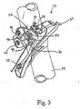
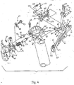
- front derailleur 12 can be used with shift cable 18 coming from above the front derailleur 12 by using cable guide adapter 22 ( Figure 2), or with shift cable 18 coming from below the front derailleur 12 ( Figure 3).
- the cable 18 can be coupled to front derailleur 12 such that its inner wire is either pulled upwardly or downwardly from front derailleur 12 by shifting unit 16.
- forward, rearward, upward, above, downward, below and transverse refer to those directions of a bicycle in its normal riding position, which front derailleur 12 is attached. Accordingly, these terms, as utilized to describe the front derailleur 12 in the claims, should be interpreted relative to bicycle 10 in its normal riding position.
- front derailleur 12 is illustrated as being fixedly coupled to seat post portion 14 of the bicycle frame, it will be apparent to those skilled in the art from this disclosure that front derailleur 12 can be coupled to other parts of the bicycle such as the bottom bracket as needed and/or desired.
- cable guide adapter 22 is preferably a C-shaped member having a pair of flanges 23 with a mounting hole 24 formed in each flange 23. Mounting holes 24 receive the threaded ends of a pair of screws or fasteners 25 therethrough for attachment to front derailleur 12.
- the edge of cable guide adapter 22 is provided with a retaining groove or recess 26 that receives the inner wire of shift cable 18 therein. Groove 26 is formed at a position to receive the inner wire of cable 18 extends from front derailleur 12.
- Cable guide adapter 22 is utilized on front derailleur 12 when it is desirable to have the shift cable 18 located above the front derailleur 12. Accordingly, cable guide adapter 22 guides the inner wire of the shift cable 18 around the edge of cable guide adapter 22 and then upwardly to the point where cable 18 is coupled to the bicycle frame.
- Two resilient retainers or hooks 27 and 28 are provided adjacent to retaining groove 26 such that the inner wire of shift cable 18 does not accidentally pop out of retaining groove 26.
- retainers 27 and 28 are substantially identical to each other, except that they are mirror images of each other.
- retainers 27 and 28 are formed integrally with the main body of cable guide adapter 22 as a one-piece, unitary member. Retainers 27 and 28 are located on opposite sides of groove 26. Retainers 27 and 28 each include an inwardly extending projection formed by an inwardly tapered surface 29 and an inner abutment surface 31 that are formed to overlie retaining groove 26. Retainers 27 and 28 are located opposite each other across groove 26, with both tapered surfaces 29 facing each other. Abutment surfaces 31 form a gap that is slightly smaller than the diameter of the inner wire of cable 18 to prevent cable 18 from popping out of groove 26 accidentally.
- front derailleur 12 includes a fixed or tubular clamping member 30, a chain guide 32 and a linkage assembly 34 coupled between fixed member 30 and chain guide 32.
- fixed member 30 is located beneath chain guide 32 and linkage assembly 34 such that chain guide 32 moves from a retracted (low gear) position to an extended (high gear) position.
- Linkage assembly 34 is preferably designed such that biasing member (torsion spring) 35 normally biases chain guide 32 in a transverse direction towards the frame of bicycle 10. In other words, when chain guide 32 is closest to the frame of bicycle 10, chain guide 3 2 holds chain 20 over the sprocket 21 that is closest to seat post portion 14.
- shifting unit 16 When linkage assembly 34 holds chain guide 32 in its extended position, chain guide 32 is located over the outermost sprocket 21, i.e., the furthest sprocket 21 from seat post portion 14. These movements of chain guide 32 and linkage assembly 34 are controlled by shifting unit 16. Specifically, when the rider squeezes the lever of shifting unit 16, this pulls shift cable 18 to move chain guide 32 between its extended position and its retracted position via linkage assembly 34. Shifting unit 16 can be a variety of types of shifting units. Therefore, the precise structure of shifting unit 16 will not be discussed or illustrated in detail herein.
- Fixed member 30 is preferably clamped directly to the seat post portion 14.
- Fixed member 30 basically includes a first C-shaped clamping portion 36, a second C-shaped clamping portion 38, a pivot pin 40 and a fastener 42.
- First and second clamping portions 36 and 38 are constructed of a rigid material to secure front derailleur 12 to seat post portion 14 of bicycle 10.
- clamping portions 36 and 38 are constructed of metal.
- clamping portions 36 and 38 could be constructed of other materials such as a hard rigid plastic material.
- the clamping portions 36 and 38 are constructed by utilizing other manufacturing techniques such as casting and/or machining.
- clamping portions 36 and 38 can also be constructed of sheet metal that is bent to the desired shape.
- First ends of clamping portions 36 and 38 are pivotally coupled together by pivot pin 40, which extends in a substantially vertical direction relative to bicycle 10.
- the other ends of clamping portions 36 and 38 are releasably connected together via fastener 42.
- Fastener 42 is preferably a screw or bolt that is threaded into a threaded hole of first clamping portion 36.
- fasterier 42 can be utilized in conjunction with a nut, or the like.
- first clamping portion 36 includes portions of linkage assembly 34.
- portions of linkage assembly 34 are integrally formed with first clamping portion 36, as explained below.
- the clamping portion 36 has a pair of substantially parallel mounting flanges 50 and 52 that extend in substantially vertical directions.
- Mounting flanges 50 and 52 each have a pivot hole 53 and 54 that receives pivot pins 55a and 55b for mounting a portion of linkage assembly 34 thereto, as explained below.
- Mounting flange 50 also has a second pivot hole 56 for receiving pivot pin 57 therein to couple another portion of linkage assembly 34 thereto.
- flange 50 forms one of the links (third link) of linkage assembly 34. Accordingly, flange 50 is a non-movable link.
- chain guide 32 is preferably constructed of a hard rigid material.
- chain guide 32 is preferably constructed of metal such as a rigid sheet metal that is bent to the desired shape.
- Chain guide 32 has a chain receiving slot 60 formed by a pair of vertical shift plates 61 and 62 that are adapted to engage chain 20 for moving chain 20 in a direction transverse to bicycle 10.
- Shift plates 61 and 62 are connected together by plates 63 and 64.
- Plate 63 is integrally formed between shift plates 61 and 62.
- Plate 64 has one end that is integrally formed with shift plate 62 and another end that is detachably coupled to shift plate 61 via screw 65.
- Chain guide 32 also has a pair of mounting flanges 66 and 67 extending in a substantially vertical direction from shift plate 61 for coupling linkage assembly 34 thereto.
- Mounting flange 66 forms one of the links of linkage assembly 34. More specifically, mounting flange 66 has a substantially horizontal section 68 and a substantially vertical section 69. Vertical section 69 has a stepped surface.
- Horizontal section 68 has a pair of threaded holes 70 and 71 for receiving adjustment screws 72 and 73 thereto.
- Adjustment screw 72 is a low position adjustment screw, while adjustment screw 73 is a high position adjustment screw. Adjustment screws 72 and 73 engage a portion of linkage assembly 34 as discussed below for controlling the range of movement of chain guide 32. In other words, by individually adjusting the axial extension of adjustment screws 72 and 73 relative to horizontal section 68, the retracted (low gear) position and the extended (high gear) position of chain guide 32 are adjusted independently of each other.
- top cover 74 is provided to overlie mounting flanges 66 and 67.
- Top cover 74 is preferably a non-metallic or plastic member that has a pair of bores 75 and 76.
- the bores 75 and 76 are initially formed with diameters that are slightly smaller than the thread diameters of adjustment screws 72 and 73. Accordingly, when adjustment screws 72 and 73 are threaded through bores 75 and 76, the non-metallic material is cut or tapped to form internal threads. This creates a friction fit between top cover 74 and adjustment screws 72 and 73. Accordingly, adjustment screws 72 and 73 will typically not move in an axial direction due to vibrations because of this frictional force between top cover 74 and adjustment screws 72 and 73, unless the screws 72 and 73 are manually adjusted by a person.
- Mounting flange 66 forms one of the links of the linkage assembly 34.
- Mounting flange 66 has a pair of pivot holes 77 and 78 for pivotally mounting a pair of links of linkage assembly 34 thereto, as discussed below.
- Mounting flange 67 has a pivot hole 79 that is aligned with pivot hole 78 of vertical section 69 for pivotally coupling a link of linkage assembly 34 therebetween.
- Linkage assembly 34 is preferably a four-bar linkage assembly having a first link 81, a second link (vertical section) 69, a third link (mounting flange) 50 and a fourth link 82.
- First link 81 has its pivot points lying on a line which is substantially parallel to a line that passes through the pivot points of fourth link 82.
- second link (vertical section) 69 has its pivot points lying on a line which is substantially parallel to a line passing through the pivot points of third link (mounting flange) 50.
- First link 81 has a cable attachment member 84 coupled thereto and cable guide adapter 22 detachably coupled thereto.
- First link 81 is pivotally coupled at one end to second link or vertical section 69 by pivot pin 86.
- the other end of first link 81 is pivotally coupled to third link or flange 50 of fixed member 30 via pivot pin 57.
- first link 81 has pivot holes 88 and 89 for receiving pivot pins 86 and 57 therein.
- First link 81 is preferably secured on pivot pins 86 and 57 by snap-on retaining washers 90. More specifically, pivot pins 86 and 57 each have a groove 92. for receiving retaining washers 90.
- these retaining washers 90 are E-shaped retaining clips that are snapped into retaining grooves 92.
- Cable attachment member 84 has a wire clamp 94 for attaching the inner wire of cable 18 thereto.
- First link 81 also has a groove 96 adjacent to wire clamp 94, such that the inner wire of cable 18 extends from wire clamp 94 along groove 96.
- wire clamp 94 is coupled to first link 81 via bolt 97.
- Fourth link 82 is pivotally mounted to second link or vertical section 69 of chain guide 32 via pivot pins 108 and 109. Specifically, pivot pins 108 and 109 are received in pivot holes 78 and 79 of flanges 66 and 67. The other end of fourth link 82 is pivotally mounted via pivot pins 55a and 55b on mounting flanges 50 and 52. Pivot pins 55a and 108 are snapped into a retaining clip 113.
- fourth link 82 is provided with a fan-shaped member 105 that engages adjustment screws 72 and 73 for limiting movement of chain guide 32 between its retracted position and its extended position. More specifically, fan member 105 is provided with a low stopping surface 106 and a high stopping surface 107 as best seen in Figures 5 and 6. Low stopping surface 106 is designed to engage the free end of low adjustment screw 72, while high stopping surface 107 is positioned to engage the high adjustment screw 73. Since this is a relatively conventional adjustment mechanism that is well known in the prior art, this adjustment mechanism will not be discussed or illustrated in detail herein.
- Biasing member 35 is preferably a torsion spring having its coiled portion positioned around pivot pin 57 therein. Biasing member 35 has a first end engaging a projection (not shown) on first link 81, and a second end engaging a projection 37 on mounting flange 50 of fixed member 30 for normally biasing chain guide 32 from its extended position to its retracted position. In other words, biasing member or torsion spring 35 is normally placed under tension to urge the cable guide 32 from its extended position to its retracted position. Of course, movement of chain guide 32 is controlled by shifting unit 16 moving cable 18 in a relatively conventional manner.
- pivot pin 57 is riveted in hole 56 of second link or flange 50, and has cable attachment member detachably coupled to the other end via one of the retaining washers 90.
- FIG. 6 a cable guide adapter 22a in accordance with a second embodiment of the present invention is illustrated.
- This embodiment of cable guide adapter 22a is similar to cable guide adapter 22 of the prior embodiment, discussed above, except that the retainers 27a and 28a of this embodiment have been modified.
- retainers 27a and 28a are longitudinally spaced apart from each other along groove 26a to form a gap therebetween.
- Retainers 27a and 28a each have inwardly extending projections formed by a tapered surface 29a and an abutment surface 31a. Abutment surfaces 31a are formed to overlie groove 26a in opposite directions to prevent cable 18 from popping out of groove 26a accidentally.
- FIG. 7 a cable guide adapter 22b in accordance with a third embodiment of the present invention is illustrated.
- This embodiment of cable guide adapter 22b is similar to cable guide adapter 22 of the prior embodiment, discussed above, except that the retainers 27b and 28b of this embodiment have been modified.
- retainers 27b have an inwardly extending projection having a tapered surface 29b, abutment surface 31b, and an inner surface 32b, which tapers away from retainer 28b as inner surface 32b approaches groove 26b.
- Retainer 28b has an inwardly extending projection having an outer surface 33b, which tapers from its free end toward retainer 27b as outer surface 33b approaches groove 26b.
- Inner surface 32b and outer surface 33b are substantially parallel.
- FIG. 8 a cable guide adapter 22c in accordance with a fourth embodiment of the present invention is illustrated.
- This embodiment of cable guide adapter 22c is similar to cable guide adapters in prior embodiments, discussed above, except that the retainers 27c and 28c of this embodiment have been modified.
- retainer 27c is formed integrally with cable guide adapter 22c as a one-piece, unitary member, whereas retainer 28c is a resilient member with one end fixedly coupled to cable guide adapter 22c by a fastener 35c.
- Retainer 27c has an inwardly extending projection formed by a tapered surface 29c and abutment surface 31c.
- Retainer 28c is preferably a sheet metal member having an inwardly extending projection formed by a bent surface 33c. Abutment surface 31c and the free end of bent surface 33c form a gap that is smaller than the diameter of the inner wire of cable 18 to prevent cable 18 from popping out of groove 26c accidentally.
Landscapes
- Engineering & Computer Science (AREA)
- Chemical & Material Sciences (AREA)
- Combustion & Propulsion (AREA)
- Transportation (AREA)
- Mechanical Engineering (AREA)
- Flexible Shafts (AREA)
- Transmissions By Endless Flexible Members (AREA)
- Gear-Shifting Mechanisms (AREA)
- Motorcycle And Bicycle Frame (AREA)
Claims (18)
- Vorderer Umwerfer für ein Fahrrad, aufweisend:ein feststehendes Element (30), das ausgebildet ist, um mit einem Abschnitt des Fahrrades (10) verbunden zu werden;eine Kettenführung (32); undeine Gelenkgetriebebaugruppe (34), die zwischen dem feststehenden Element (30) und der Kettenführung (32) angelenkt ist, um die Kettenführung (32) zwischen einer zurückgezogenen Position und einer ausgefahrenen Position zu bewegen, wobei die Gelenkgetriebebaugruppe (34) beinhaltet:ein Vorspannelement (35) und ein erstes Getriebeglied (81), das relativ zu dem feststehenden Element (30) schwenkbar angelenkt ist, wobei das erste Getriebeglied ein mit diesem verbundenes Kabelbefestigungselement (84), das ein Schaltkabel (18) mit diesem verbindet, und einen abnehmbaren Kabelführungsadapter (22; 22a; 22b; 22c) aufweist, der eine Kabelaufnahmefläche aufweist, die konfiguriert und angeordnet ist, um das Schaltkabel (18) von diesem nach oben zu führen,
dadurch gekennzeichnet, dass der Kabelführungsadapter (22; 22a; 22b; 22c) eine Rückhalteeinrichtung (27, 28; 27a, 28a; 27b, 28b; 27c, 28c) beinhaltet, um das Schaltkabel (18) auf der Kabelaufnahmefläche des Kabelführungsadapters zurückzuhalten. - Vorderer Umwerfer für ein Fahrrad gemäß Anspruch 1, bei dem
die Kabelaufnahmefläche eine Nut (26; 26a; 26b; 26c) zur Führung des Schaltkabels (18) beinhaltet. - Vorderer Umwerfer für ein Fahrrad nach Anspruch 2, bei dem
die Rückhalteeinrichtung (27, 28; 27a, 28a; 27b, 28b; 27c, 28c) so ausgebildet ist, dass sie zumindest teilweise über der Nut (26; 26a; 26b; 26c) zu liegen kommt. - Vorderer Umwerfer für ein Fahrrad nach Anspruch 2 oder 3, bei dem
die Rückhalteeinrichtung erste und zweite Vorsprünge (27, 28; 27a, 28a; 27b, 28b; 27c, 28c) beinhaltet. - Vorderer Umwerfer für ein Fahrrad nach Anspruch 4, bei dem
die ersten und zweiten Vorsprünge (27, 28; 27a, 28a; 27b, 28b; 27c, 28c) auf entgegengesetzten Seiten der Nut (26; 26a; 26b; 26c) ausgebildet sind. - Vorderer Umwerfer für ein Fahrrad nach Anspruch 4 oder 5, bei dem
die ersten und zweiten Vorsprünge (27, 28; 27a, 28a; 27b, 28b) integral mit dem Kabelführungsadapter (22; 22a; 22b) als einstückiges unitäres Teil des Kabelführungsadapters (22; 22a; 22b) ausgebildet sind. - Vorderer Umwerfer für ein Fahrrad nach einem der Ansprüche 4 bis 6, bei dem
die ersten und zweiten Vorsprünge (27, 28; 27b, 28b; 27c, 28c) einander gegenüberliegend ausgebildet sind. - Vorderer Umwerfer für ein Fahrrad nach einem der Ansprüche 4 bis 6, bei dem
die ersten und zweiten Vorsprünge (27a, 28a) in Längsrichtung mit Abstand zueinander entlang der Nut (26a) angeordnet sind, um einen Spalt zwischen sich zu bilden. - Vorderer Umwerfer für ein Fahrrad nach einem der Ansprüche 4 bis 7, bei dem
der erste Vorsprung (27b) eine Innenfläche (32b) beinhaltet, die sich in Richtung von dem zweiten Vorsprung (28b) weg verjüngt, und zwar im Verlauf der Annäherung der Innenfläche (32b) an die Nut (26b), und
der zweite Vorsprung (28b) eine Außenfläche (33b) beinhaltet, die sich ausgehend von ihrem freien Ende in Richtung zum ersten Vorsprung (27b) hin verjüngt, und zwar im Verlauf der Annäherung der Außenfläche (32b) an die Nut (26b), wobei die Innen- und Außenflächen (32b, 33b) im Wesentlichen parallel sind. - Vorderer Umwerfer für ein Fahrrad nach einem der Ansprüche 4 oder 5, bei dem
der erste Vorsprung (27c) integral mit dem Kabelführungsadapter (22c) als einstückiges unitäres Teil des Kabelführungsadapters (22c) ausgebildet ist, und
der zweite Vorsprung (28c) ein elastisches Element ist, dessen eines Ende mit dem Kabelführungsadapter (22c) durch ein Befestigungselement (35c) fest verbunden ist. - Vorderer Umwerfer für ein Fahrrad nach einem der vorhergehenden Ansprüche, bei dem
der Kabelführungsadapter (22) eine Befestigungseinrichtung (24, 25) beinhaltet, um den Kabelführungsadapter mit dieser lösbar zu verbinden. - Vorderer Umwerfer für ein Fahrrad nach Anspruch 11, bei dem
die Befestigungseinrichtung mindestens eine Befestigungseinrichtung (25) beinhaltet, die den Kabelführungsadapter (22) am ersten Getriebeglied (81) abnehmbar befestigt. - Vorderer Umwerfer für ein Fahrrad nach einem der vorhergehenden Ansprüche, bei dem
die Kettenführung (32) sich oberhalb des feststehenden Elementes (30) befindet, wenn sie am Fahrrad (10) montiert ist. - Vorderer Umwerfer für ein Fahrrad nach einem der vorhergehenden Ansprüche, bei dem
das Vorspannelement eine Torsionsfeder (35) ist, die mit dem ersten Getriebeglied (81) in Eingriff ist. - Vorderer Umwerfer für ein Fahrrad nach einem der vorhergehenden Ansprüche, bei dem
die Gelenkgetriebebaugruppe (34) ein Viergelenkgetriebe bildet, dessen zweites Getriebeglied (69) durch die Kettenführung (32) gebildet ist, dessen drittes Getriebeglied (50) durch das feststehende Element (30) gebildet ist und dessen viertes Getriebeglied (82) zwischen dem zweiten (69) und dem dritten Getriebeglied (50) schwenkbar angelenkt ist. - Vorderer Umwerfer für ein Fahrrad nach einem der Ansprüche 1 bis 14, bei dem
die Gelenkgetriebebaugruppe (34) weiter ein zweites Getriebeglied (69) beinhaltet, das mit der Kettenführung (32) starr verbunden ist, um sich zusammen mit dieser zu bewegen. - Vorderer Umwerfer für ein Fahrrad nach Anspruch 16, bei dem
das erste Getriebeglied (81) durch einen ersten Schwenkstift (57) an einem durch das feststehende Element (30) gebildeten dritten Getriebeglied (50) schwenkbar angelenkt ist und an dem zweiten Getriebeglied (69) der Kettenführung (32) schwenkbar angelenkt ist, und
das Vorspannelement (35) ein erstes Ende aufweist, das mit dem ersten Getriebeglied (81) in Eingriff ist, und ein zweites Ende, das mit dem feststehenden Element (30) in Eingriff ist. - Vorderer Umwerfer für ein Fahrrad nach Anspruch 17, bei dem
die Gelenkgetriebebaugruppe (34) ein viertes Getriebeglied (82) beinhaltet, das an einem ersten Ende am zweiten Getriebeglied (69) schwenkbar angelenkt ist und an einem zweiten Ende am dritten Getriebeglied (50) des feststehenden Elementes (30) schwenkbar angelenkt ist.
Applications Claiming Priority (2)
| Application Number | Priority Date | Filing Date | Title |
|---|---|---|---|
| US09/280,084 US6099425A (en) | 1999-03-29 | 1999-03-29 | Front derailleur for a bicycle |
| US280084 | 1999-03-29 |
Publications (3)
| Publication Number | Publication Date |
|---|---|
| EP1040992A2 EP1040992A2 (de) | 2000-10-04 |
| EP1040992A3 EP1040992A3 (de) | 2002-01-09 |
| EP1040992B1 true EP1040992B1 (de) | 2006-02-22 |
Family
ID=23071591
Family Applications (1)
| Application Number | Title | Priority Date | Filing Date |
|---|---|---|---|
| EP00105295A Expired - Lifetime EP1040992B1 (de) | 1999-03-29 | 2000-03-14 | Vordere Gangschaltung für Fahrrad |
Country Status (6)
| Country | Link |
|---|---|
| US (1) | US6099425A (de) |
| EP (1) | EP1040992B1 (de) |
| JP (1) | JP3556147B2 (de) |
| CN (1) | CN1142874C (de) |
| DE (1) | DE60026088T2 (de) |
| TW (1) | TW547431U (de) |
Families Citing this family (31)
| Publication number | Priority date | Publication date | Assignee | Title |
|---|---|---|---|---|
| US6726587B2 (en) * | 2001-10-19 | 2004-04-27 | Shimano, Inc. | Adjustable bicycle derailleur |
| US6923740B2 (en) * | 2001-11-26 | 2005-08-02 | Shimano Inc. | Front derailleur for a bicycle |
| US7014584B2 (en) * | 2002-12-27 | 2006-03-21 | Shimano Inc. | Top pull type front derailleur |
| US6902503B2 (en) * | 2003-02-27 | 2005-06-07 | Shimano Inc. | Bicycle derailleur |
| JP2005186764A (ja) * | 2003-12-25 | 2005-07-14 | Shimano Inc | 自転車用フロントディレイラ |
| DE102004037740A1 (de) * | 2004-08-04 | 2006-03-16 | Sram Deutschland Gmbh | Flexibler Schelleneinsatz |
| US7438657B2 (en) * | 2005-05-27 | 2008-10-21 | Shimano Inc. | Bicycle front derailleur |
| DE102005050988A1 (de) * | 2005-10-25 | 2007-06-14 | Sram Deutschland Gmbh | Kettenumwerfer |
| US7722486B2 (en) * | 2005-12-14 | 2010-05-25 | Shimano Inc. | Top/bottom pull bicycle front derailleur |
| US7867118B2 (en) * | 2006-06-15 | 2011-01-11 | Shimano Inc. | Bicycle front derailleur |
| US7914407B2 (en) * | 2007-05-29 | 2011-03-29 | Shimano Inc. | Bicycle front derailleur assembly |
| US8337343B2 (en) * | 2010-03-06 | 2012-12-25 | Chang Hui Lin | Front derailleur of bicycle |
| DE102010011391A1 (de) | 2010-03-12 | 2011-09-15 | Sram Deutschland Gmbh | Seilzugbetätigungseinrichtung für Fahrrad-Kettenwerfer |
| US9033833B2 (en) | 2011-01-28 | 2015-05-19 | Paha Designs, Llc | Gear transmission and derailleur system |
| US9327792B2 (en) | 2011-01-28 | 2016-05-03 | Paha Designs, Llc | Gear transmission and derailleur system |
| US10207772B2 (en) | 2011-01-28 | 2019-02-19 | Paha Designs, Llc | Gear transmission and derailleur system |
| US8932162B2 (en) * | 2013-05-21 | 2015-01-13 | Shimano Inc. | Bicycle front derailleur |
| US9156524B2 (en) * | 2013-09-30 | 2015-10-13 | Shimano Inc. | Derailleur |
| US9216794B2 (en) * | 2013-05-23 | 2015-12-22 | Shimano Inc. | Front derailleur |
| US9248885B2 (en) * | 2013-09-30 | 2016-02-02 | Shimano Inc. | Derailleur |
| US9457871B2 (en) * | 2014-09-08 | 2016-10-04 | Shimano Inc. | Bicycle front derailleur |
| US9434448B2 (en) * | 2014-10-31 | 2016-09-06 | Shimano Inc. | Bicycle derailleur |
| US9616970B2 (en) * | 2015-07-03 | 2017-04-11 | Shimano Inc. | Bicycle derailleur |
| US9873482B2 (en) * | 2015-10-09 | 2018-01-23 | Shimano Inc. | Bicycle front derailleur |
| US10086905B2 (en) * | 2016-03-22 | 2018-10-02 | Shimano Inc. | Bicycle front derailleur with mounting bracket |
| US10252773B2 (en) * | 2016-04-05 | 2019-04-09 | Shimano Inc. | Bicycle front derailleur |
| US10407128B2 (en) * | 2016-09-30 | 2019-09-10 | Shimano Inc. | Bicycle derailleur |
| US10131404B2 (en) * | 2017-02-09 | 2018-11-20 | Shimano Inc. | Bicycle front derailleur |
| IT201700015324A1 (it) * | 2017-02-13 | 2018-08-13 | Campagnolo Srl | Deragliatore anteriore per bicicletta |
| TWI789225B (zh) * | 2022-01-27 | 2023-01-01 | 台灣微轉股份有限公司 | 自行車前撥鏈器 |
| TWI830413B (zh) * | 2022-09-30 | 2024-01-21 | 台灣微轉股份有限公司 | 自行車前撥鏈器 |
Family Cites Families (3)
| Publication number | Priority date | Publication date | Assignee | Title |
|---|---|---|---|---|
| DE69423175T2 (de) * | 1993-11-12 | 2000-09-14 | Shimano Kk | Vorderer Umwerfer für ein Fahrrad |
| US5779581A (en) * | 1996-06-19 | 1998-07-14 | Shimano, Inc. | Top pull front derailleur |
| DE19703933B4 (de) * | 1997-02-04 | 2008-01-03 | Sram Deutschland Gmbh | Kettenumlegeeinrichtung für Fahrräder |
-
1999
- 1999-03-29 US US09/280,084 patent/US6099425A/en not_active Expired - Lifetime
-
2000
- 2000-01-11 TW TW091215688U patent/TW547431U/zh not_active IP Right Cessation
- 2000-01-14 CN CNB001010824A patent/CN1142874C/zh not_active Expired - Fee Related
- 2000-03-14 DE DE60026088T patent/DE60026088T2/de not_active Expired - Lifetime
- 2000-03-14 EP EP00105295A patent/EP1040992B1/de not_active Expired - Lifetime
- 2000-03-22 JP JP2000079587A patent/JP3556147B2/ja not_active Expired - Fee Related
Also Published As
| Publication number | Publication date |
|---|---|
| US6099425A (en) | 2000-08-08 |
| EP1040992A3 (de) | 2002-01-09 |
| CN1268461A (zh) | 2000-10-04 |
| DE60026088D1 (de) | 2006-04-27 |
| JP2000280971A (ja) | 2000-10-10 |
| JP3556147B2 (ja) | 2004-08-18 |
| DE60026088T2 (de) | 2006-08-10 |
| CN1142874C (zh) | 2004-03-24 |
| EP1040992A2 (de) | 2000-10-04 |
| TW547431U (en) | 2003-08-11 |
Similar Documents
| Publication | Publication Date | Title |
|---|---|---|
| EP1040992B1 (de) | Vordere Gangschaltung für Fahrrad | |
| EP1040991B1 (de) | Bandförmiger Adapter für vordere Gangschaltung | |
| EP1031504B1 (de) | Vorderer Umwerfer für ein Fahrrad | |
| US6962544B2 (en) | Front derailleur for a bicycle | |
| EP1433696B2 (de) | Vorderer Umwerfer | |
| EP2196385B1 (de) | Fahrradbetätigungsvorrichtung | |
| EP1447317B1 (de) | Vorderer Umwerfer für ein Fahrrad | |
| EP1798143B3 (de) | Vorderer Umwerfer für ein Fahrrad | |
| US7438657B2 (en) | Bicycle front derailleur | |
| US8485924B2 (en) | Bicycle chain guide | |
| EP1790563A2 (de) | Vorderer Umwerfer mit Winkeleinstellvorrichtung für ein Fahrrad | |
| US20080004142A1 (en) | Bicycle front derailleur | |
| EP1640260A2 (de) | Befestigungsanordnung für einen vorderen Gangumwerfer |
Legal Events
| Date | Code | Title | Description |
|---|---|---|---|
| PUAI | Public reference made under article 153(3) epc to a published international application that has entered the european phase |
Free format text: ORIGINAL CODE: 0009012 |
|
| AK | Designated contracting states |
Kind code of ref document: A2 Designated state(s): AT BE CH CY DE DK ES FI FR GB GR IE IT LI LU MC NL PT SE Kind code of ref document: A2 Designated state(s): DE FR IE IT NL |
|
| AX | Request for extension of the european patent |
Free format text: AL;LT;LV;MK;RO;SI |
|
| PUAL | Search report despatched |
Free format text: ORIGINAL CODE: 0009013 |
|
| AK | Designated contracting states |
Kind code of ref document: A3 Designated state(s): AT BE CH CY DE DK ES FI FR GB GR IE IT LI LU MC NL PT SE |
|
| AX | Request for extension of the european patent |
Free format text: AL;LT;LV;MK;RO;SI |
|
| 17P | Request for examination filed |
Effective date: 20020212 |
|
| AKX | Designation fees paid |
Free format text: DE FR IE IT NL |
|
| 17Q | First examination report despatched |
Effective date: 20040729 |
|
| GRAP | Despatch of communication of intention to grant a patent |
Free format text: ORIGINAL CODE: EPIDOSNIGR1 |
|
| GRAS | Grant fee paid |
Free format text: ORIGINAL CODE: EPIDOSNIGR3 |
|
| GRAA | (expected) grant |
Free format text: ORIGINAL CODE: 0009210 |
|
| AK | Designated contracting states |
Kind code of ref document: B1 Designated state(s): DE FR IE IT NL |
|
| PG25 | Lapsed in a contracting state [announced via postgrant information from national office to epo] |
Ref country code: IE Free format text: LAPSE BECAUSE OF NON-PAYMENT OF DUE FEES Effective date: 20060314 |
|
| PGFP | Annual fee paid to national office [announced via postgrant information from national office to epo] |
Ref country code: FR Payment date: 20060322 Year of fee payment: 7 |
|
| REG | Reference to a national code |
Ref country code: IE Ref legal event code: FG4D |
|
| PGFP | Annual fee paid to national office [announced via postgrant information from national office to epo] |
Ref country code: IT Payment date: 20060331 Year of fee payment: 7 |
|
| REF | Corresponds to: |
Ref document number: 60026088 Country of ref document: DE Date of ref document: 20060427 Kind code of ref document: P |
|
| RAP2 | Party data changed (patent owner data changed or rights of a patent transferred) |
Owner name: SHIMANO INC. |
|
| NLT2 | Nl: modifications (of names), taken from the european patent patent bulletin |
Owner name: SHIMANO INC. Effective date: 20060802 |
|
| ET | Fr: translation filed | ||
| PLBE | No opposition filed within time limit |
Free format text: ORIGINAL CODE: 0009261 |
|
| STAA | Information on the status of an ep patent application or granted ep patent |
Free format text: STATUS: NO OPPOSITION FILED WITHIN TIME LIMIT |
|
| 26N | No opposition filed |
Effective date: 20061123 |
|
| PGFP | Annual fee paid to national office [announced via postgrant information from national office to epo] |
Ref country code: NL Payment date: 20070315 Year of fee payment: 8 |
|
| REG | Reference to a national code |
Ref country code: FR Ref legal event code: ST Effective date: 20071130 |
|
| PG25 | Lapsed in a contracting state [announced via postgrant information from national office to epo] |
Ref country code: FR Free format text: LAPSE BECAUSE OF NON-PAYMENT OF DUE FEES Effective date: 20070402 |
|
| PG25 | Lapsed in a contracting state [announced via postgrant information from national office to epo] |
Ref country code: NL Free format text: LAPSE BECAUSE OF NON-PAYMENT OF DUE FEES Effective date: 20081001 |
|
| NLV4 | Nl: lapsed or anulled due to non-payment of the annual fee |
Effective date: 20081001 |
|
| PG25 | Lapsed in a contracting state [announced via postgrant information from national office to epo] |
Ref country code: IT Free format text: LAPSE BECAUSE OF NON-PAYMENT OF DUE FEES Effective date: 20070314 |
|
| PGFP | Annual fee paid to national office [announced via postgrant information from national office to epo] |
Ref country code: DE Payment date: 20160308 Year of fee payment: 17 |
|
| REG | Reference to a national code |
Ref country code: DE Ref legal event code: R119 Ref document number: 60026088 Country of ref document: DE |
|
| PG25 | Lapsed in a contracting state [announced via postgrant information from national office to epo] |
Ref country code: DE Free format text: LAPSE BECAUSE OF NON-PAYMENT OF DUE FEES Effective date: 20171003 |