EP1807687B1 - Kraftmesselement - Google Patents
Kraftmesselement Download PDFInfo
- Publication number
- EP1807687B1 EP1807687B1 EP04762352.5A EP04762352A EP1807687B1 EP 1807687 B1 EP1807687 B1 EP 1807687B1 EP 04762352 A EP04762352 A EP 04762352A EP 1807687 B1 EP1807687 B1 EP 1807687B1
- Authority
- EP
- European Patent Office
- Prior art keywords
- screw according
- screw
- bolt
- force
- divided
- Prior art date
- Legal status (The legal status is an assumption and is not a legal conclusion. Google has not performed a legal analysis and makes no representation as to the accuracy of the status listed.)
- Expired - Lifetime
Links
- 239000012528 membrane Substances 0.000 claims description 28
- 238000013461 design Methods 0.000 claims description 6
- 125000006850 spacer group Chemical group 0.000 claims description 4
- 239000010409 thin film Substances 0.000 claims description 4
- 229910000831 Steel Inorganic materials 0.000 claims description 3
- 238000009412 basement excavation Methods 0.000 claims description 3
- 238000005516 engineering process Methods 0.000 claims description 3
- 239000010959 steel Substances 0.000 claims description 3
- 230000005540 biological transmission Effects 0.000 claims 1
- 238000005259 measurement Methods 0.000 description 9
- 238000004519 manufacturing process Methods 0.000 description 7
- 239000000463 material Substances 0.000 description 5
- 238000000034 method Methods 0.000 description 5
- 230000008901 benefit Effects 0.000 description 4
- 230000001419 dependent effect Effects 0.000 description 4
- 230000009471 action Effects 0.000 description 2
- 238000001514 detection method Methods 0.000 description 2
- 238000011156 evaluation Methods 0.000 description 2
- 238000005304 joining Methods 0.000 description 2
- 238000003466 welding Methods 0.000 description 2
- 230000008859 change Effects 0.000 description 1
- 238000010276 construction Methods 0.000 description 1
- 230000007547 defect Effects 0.000 description 1
- 238000011161 development Methods 0.000 description 1
- 238000006073 displacement reaction Methods 0.000 description 1
- 238000009826 distribution Methods 0.000 description 1
- 238000009434 installation Methods 0.000 description 1
- 230000010354 integration Effects 0.000 description 1
- 230000002093 peripheral effect Effects 0.000 description 1
- 230000008569 process Effects 0.000 description 1
- 238000007789 sealing Methods 0.000 description 1
- 239000011343 solid material Substances 0.000 description 1
Images
Classifications
-
- G—PHYSICS
- G01—MEASURING; TESTING
- G01L—MEASURING FORCE, STRESS, TORQUE, WORK, MECHANICAL POWER, MECHANICAL EFFICIENCY, OR FLUID PRESSURE
- G01L1/00—Measuring force or stress, in general
- G01L1/20—Measuring force or stress, in general by measuring variations in ohmic resistance of solid materials or of electrically-conductive fluids; by making use of electrokinetic cells, i.e. liquid-containing cells wherein an electrical potential is produced or varied upon the application of stress
- G01L1/22—Measuring force or stress, in general by measuring variations in ohmic resistance of solid materials or of electrically-conductive fluids; by making use of electrokinetic cells, i.e. liquid-containing cells wherein an electrical potential is produced or varied upon the application of stress using resistance strain gauges
- G01L1/2206—Special supports with preselected places to mount the resistance strain gauges; Mounting of supports
- G01L1/2231—Special supports with preselected places to mount the resistance strain gauges; Mounting of supports the supports being disc- or ring-shaped, adapted for measuring a force along a single direction
- G01L1/2237—Special supports with preselected places to mount the resistance strain gauges; Mounting of supports the supports being disc- or ring-shaped, adapted for measuring a force along a single direction the direction being perpendicular to the central axis
-
- G—PHYSICS
- G01—MEASURING; TESTING
- G01L—MEASURING FORCE, STRESS, TORQUE, WORK, MECHANICAL POWER, MECHANICAL EFFICIENCY, OR FLUID PRESSURE
- G01L1/00—Measuring force or stress, in general
- G01L1/26—Auxiliary measures taken, or devices used, in connection with the measurement of force, e.g. for preventing influence of transverse components of force, for preventing overload
-
- G—PHYSICS
- G01—MEASURING; TESTING
- G01L—MEASURING FORCE, STRESS, TORQUE, WORK, MECHANICAL POWER, MECHANICAL EFFICIENCY, OR FLUID PRESSURE
- G01L5/00—Apparatus for, or methods of, measuring force, work, mechanical power, or torque, specially adapted for specific purposes
- G01L5/0004—Force transducers adapted for mounting in a bore of the force receiving structure
-
- G—PHYSICS
- G01—MEASURING; TESTING
- G01L—MEASURING FORCE, STRESS, TORQUE, WORK, MECHANICAL POWER, MECHANICAL EFFICIENCY, OR FLUID PRESSURE
- G01L5/00—Apparatus for, or methods of, measuring force, work, mechanical power, or torque, specially adapted for specific purposes
- G01L5/16—Apparatus for, or methods of, measuring force, work, mechanical power, or torque, specially adapted for specific purposes for measuring several components of force
- G01L5/161—Apparatus for, or methods of, measuring force, work, mechanical power, or torque, specially adapted for specific purposes for measuring several components of force using variations in ohmic resistance
- G01L5/162—Apparatus for, or methods of, measuring force, work, mechanical power, or torque, specially adapted for specific purposes for measuring several components of force using variations in ohmic resistance of piezoresistors
-
- G—PHYSICS
- G01—MEASURING; TESTING
- G01L—MEASURING FORCE, STRESS, TORQUE, WORK, MECHANICAL POWER, MECHANICAL EFFICIENCY, OR FLUID PRESSURE
- G01L5/00—Apparatus for, or methods of, measuring force, work, mechanical power, or torque, specially adapted for specific purposes
- G01L5/16—Apparatus for, or methods of, measuring force, work, mechanical power, or torque, specially adapted for specific purposes for measuring several components of force
- G01L5/161—Apparatus for, or methods of, measuring force, work, mechanical power, or torque, specially adapted for specific purposes for measuring several components of force using variations in ohmic resistance
- G01L5/1627—Apparatus for, or methods of, measuring force, work, mechanical power, or torque, specially adapted for specific purposes for measuring several components of force using variations in ohmic resistance of strain gauges
Definitions
- the invention is based on a screw as a force measuring element according to the preamble of the independent claim.
- the DE 199 60 186 A1 shows a Radialkraftier disturb with the features of the preamble of claim 1.
- WO 00/16054 A1 shows a motor vehicle seat with integrated occupancy detection.
- a sensor For occupancy detection with a sensor a vertical displacement between a top frame and a base of the vehicle seat measured.
- This measuring transducer consists of a bolt and a head, which contains an elastic element for force measurement.
- the force should be on the sleeve like this be applied, that the direction of force is perpendicular to the bolt.
- the force is applied at a different angle to the sleeve, in which case the screw according to the invention as a force measuring element measures substantially the force component perpendicular to the bolt, which causes the strain on the membrane substantially.
- the application or application of the strain-measuring sensors is particularly simple, since they are located in one plane. Thus, thin-film methods for applying the strain-measuring sensor technology can also be used.
- the strain-measuring sensor can consist of several strain-measuring elements.
- the screw according to the invention can be made in one piece. This allows a particularly simple production of the screw according to the invention.
- the screw can be rotationally symmetrical, with slight deviations from the rotational symmetry not influencing the function of the screw.
- the design of the screw as a force measuring element allows for particularly simple installation of the force measuring element in various applications, for example, to measure the force applied to a vehicle seat weight.
- the strain-measuring sensor has strain gauges, which are preferably connected in a Wheatstone bridge in order to allow an accurate measurement.
- the sensor system has piezoresistive elements in order to measure the elongation via the piezoresistive defect. These elements can be applied to the membrane of the force-sensing element in a thin-film process.
- the screw according to the invention in one piece, it is possible to connect the sleeve, bolt and diaphragm by joints.
- welding can be used as the joining technique.
- different materials for sleeve, diaphragm and bolt The manufacturing technology can thus be further simplified.
- the joints are easily accessible and thus allow easy connection of the components.
- the joints between the sleeve and the membrane and the membrane and the bolt can be offset from each other. This allows an even easier production of the screw according to the invention.
- the screw has an internal design of free spaces by an appropriate design of the bolt, the membrane and the sleeve to make the strain-intensive areas on the membrane even better and more sensitive. This allows a greater stroke in the strain as a function of the force and thus a better measurement of the force.
- the membrane element may be designed only annular, so as to be arranged only in the areas of high strain, which means a saving of material of the high-strength material.
- joints can also be designed annular, which means a particularly simple production of the screw according to the invention. In this case, then the annular membrane is used.
- a screw is proposed as a force measuring element, which allows a force and / or torque measurement with a special design.
- the Screw consists of simple geometric elements that are easy to manufacture and allow minimal space.
- strain-measuring sensors because the strain is measured with the force measuring element, ensures that only forces can be sensed primarily in one direction.
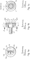
- FIG. 1a shows a front view of the screw. In the front view, only the membrane 3 with the applied strain-dependent resistors 14 and the connecting lines 15 and the electrical connections 16 can be seen.
- the strain-dependent resistors 14 are arranged on the one hand in a region 12a, which is under load application under load. On the other hand, they are arranged in a region 13a which is under compressive stress during load application.
- the region 12a is the tensile stress region, while the region 13a is the compressive stress region in the force action direction F shown.
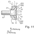
- FIG. 1b shows a side view in section of the screw according to the invention.
- the screw has a bolt which connects a threaded part 17 with the membrane 3.
- the membrane 3 has a larger diameter than the pin 2 and is connected in its outer regions with a sleeve 1, which is also rotationally symmetrical as the Membrane 3 and the bolt 2 and the threaded part 17 are.
- the membrane 3 has elevations 200 in the outer third, which then define the regions 4 which are subject to high expansion.
- the sleeve 1 here has a shoulder 19, on which the force F is applied perpendicular to the longitudinal direction of the bolt 2 and the threaded part 17.
- the force is applied via the shoulder 19 on the sleeve 1 with the force F. This creates a moment in the force measuring element. This moment acts between the sleeve 1 and the bolt 2 with the membrane 3 therebetween, which is wound by the torque introduction.
- strain or voltage measuring elements On the strongly expanding annular peripheral part of the membrane 4, strain or voltage measuring elements, for. As strain gauges, piezoresistive structures or thin film structures applied.
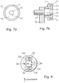
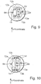
- FIG. 8 . 9 and 10 show variations of the arrangement of the strain gauges.
- the advantage of these arrangements is the change in the resistance of all four resistors. Two are in a tensioned area, the remaining two are in a stressed area.
- FIG. 8 shows strain-measuring elements, which are each arranged at the edge of the thin-walled membrane region.
- the resistors 14 in the region 12a, 13b are under tension when the load is applied in the negative Z direction.
- the resistors 14 in the region 12b, 13a are under compressive stress.
- the connections 84 lead to the measurement evaluation.
- the strain-dependent resistors 12a, 12b, 13a, 13b are connected in a Wheatstone bridge.
- FIG. 9 shows a further variation, which exploits only the area 12a and 13a.
- the resistors 14 so that a force in the negative z-direction causes a train voltage in the region 12a and a pressure voltage in 13a.
- a similar arrangement is also possible with the area 12b or 13b. This will be in FIG. 10 shown. Here are the resistors 14 so that a force in the negative z-direction causes a pressure in the region 12b and a train voltage in 13b.
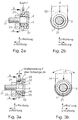
- FIG. 2 This will be in FIG. 2 shown. Same elements are here with the same reference numerals as in FIG. 1 designated.
- a fixed clamping 23 is shown, which can be done for example by screwing the threaded part 17 into a thread.
- FIG. 2a which also shows another side view in section of the force measuring element ( FIG. 2b ), a rocker 22 is shown, which serves to initiate the force.
- the force is introduced via the rocker 22 and the force is derived via the fixed clamping 23.
- the swingarm decouples the moments around the Y-axis of the screw.
- FIG. 3 again shows a side view of the screw in section in the image a, in which case the same parts are designated by the same reference numerals.
- a redesigned rocker 24 and sleeve 1 is used.
- the sleeve may have a clearance 31 to give the rocker 24 in the direction of rotation 32 the necessary clearance.
- the direction of rotation 32 in Figure 3a and 3b for torque decoupling in all spatial axes, for example, by sockets 25 on the rocker 24 allows.
- the socket may consist of two interlocking elements, each having a spherical surface 25 with, in FIG. 3a shown, the same center M and the same radius 30 have.
- the spherical surface of the rocker 24 points inwards (towards the center M), the spherical surface of the bearing 26 outwardly away from the center M. Both surfaces to each other can have a slight play to allow the rotational movement.
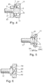
- FIG. 5 shows another side view in section. Now, the joints 11 and the joints 10 are no longer as in FIG. 4 in a plane, but offset each other.
- the offset 50 allows a better production of the screw according to the invention.
Landscapes
- Physics & Mathematics (AREA)
- General Physics & Mathematics (AREA)
- Force Measurement Appropriate To Specific Purposes (AREA)
- Measurement Of Force In General (AREA)
Applications Claiming Priority (1)
| Application Number | Priority Date | Filing Date | Title |
|---|---|---|---|
| PCT/DE2004/001454 WO2006005273A1 (de) | 2004-07-07 | 2004-07-07 | Kraftmesselement |
Publications (2)
| Publication Number | Publication Date |
|---|---|
| EP1807687A1 EP1807687A1 (de) | 2007-07-18 |
| EP1807687B1 true EP1807687B1 (de) | 2017-09-13 |
Family
ID=34958206
Family Applications (1)
| Application Number | Title | Priority Date | Filing Date |
|---|---|---|---|
| EP04762352.5A Expired - Lifetime EP1807687B1 (de) | 2004-07-07 | 2004-07-07 | Kraftmesselement |
Country Status (4)
| Country | Link |
|---|---|
| US (1) | US7819017B2 (enExample) |
| EP (1) | EP1807687B1 (enExample) |
| JP (1) | JP5248856B2 (enExample) |
| WO (1) | WO2006005273A1 (enExample) |
Families Citing this family (14)
| Publication number | Priority date | Publication date | Assignee | Title |
|---|---|---|---|---|
| JP5195451B2 (ja) * | 2008-04-15 | 2013-05-08 | 株式会社デンソー | 燃料噴射装置、それに用いられる蓄圧式燃料噴射装置システム |
| JP2013035525A (ja) * | 2011-08-10 | 2013-02-21 | Ts Tech Co Ltd | 荷重測定センサの取付構造 |
| US9038487B2 (en) | 2011-07-28 | 2015-05-26 | Ts Tech Co., Ltd. | Support structure for load measurement sensor |
| JP5960514B2 (ja) * | 2012-06-08 | 2016-08-02 | テイ・エス テック株式会社 | 荷重測定センサを取り付ける取付構造 |
| JP5815320B2 (ja) * | 2011-07-28 | 2015-11-17 | テイ・エス テック株式会社 | 荷重測定センサの取付構造 |
| JP2013035524A (ja) * | 2011-08-10 | 2013-02-21 | Ts Tech Co Ltd | 荷重測定センサの取付構造 |
| JP2013028269A (ja) * | 2011-07-28 | 2013-02-07 | Ts Tech Co Ltd | 荷重測定センサを取り付ける取付構造 |
| WO2013022063A1 (ja) * | 2011-08-10 | 2013-02-14 | テイ・エス テック株式会社 | 荷重測定センサの支持構造 |
| US8887585B2 (en) * | 2011-11-26 | 2014-11-18 | Tecsis Gmbh | Force-sensing device for measuring a traction-and/or pressure force load in structure |
| US8893557B2 (en) * | 2013-01-09 | 2014-11-25 | King Fahd University Of Petroleum And Minerals | Fastener tension monitoring system |
| US9297687B2 (en) * | 2013-05-17 | 2016-03-29 | Sensata Technologies, Inc. | Sense element having a stud fitted within the sense element |
| US9429485B1 (en) * | 2015-03-12 | 2016-08-30 | The United States Of America As Represented By The Secretary Of The Navy | Bolt shear force sensor |
| CN110133329B (zh) * | 2019-05-10 | 2021-10-01 | 江苏塔菲尔新能源科技股份有限公司 | 测试夹具 |
| EP4469769A2 (en) * | 2022-03-17 | 2024-12-04 | Sensata Technologies, Inc. | Brake pedal with force sensor and membranes |
Family Cites Families (22)
| Publication number | Priority date | Publication date | Assignee | Title |
|---|---|---|---|---|
| US3812758A (en) * | 1972-10-24 | 1974-05-28 | Kaman Aerospace Corp | Bolt head which measures and maintains preload |
| JPS5687195A (en) * | 1979-12-19 | 1981-07-15 | Hitachi Ltd | Differential pressure transmitter |
| JPS60239630A (ja) * | 1984-05-14 | 1985-11-28 | Yamato Scale Co Ltd | 計重機 |
| JPS61184930A (ja) | 1985-02-13 | 1986-08-18 | Nec Corp | 誤り訂正符号器 |
| JPS61184930U (enExample) * | 1985-05-08 | 1986-11-18 | ||
| JPH0439553Y2 (enExample) * | 1986-10-17 | 1992-09-16 | ||
| JPH01253622A (ja) * | 1988-04-01 | 1989-10-09 | Kyowa Electron Instr Co Ltd | ダイヤフラム型荷重変換器 |
| US4823606A (en) * | 1988-06-23 | 1989-04-25 | Carron & Company | Diaphragm transducer for sensing loading |
| JPH0387622A (ja) * | 1989-08-30 | 1991-04-12 | Nec Corp | 力覚センサ及びその製造方法 |
| US5094109A (en) * | 1990-12-06 | 1992-03-10 | Rosemount Inc. | Pressure transmitter with stress isolation depression |
| JP3275116B2 (ja) * | 1993-06-11 | 2002-04-15 | ニッタ株式会社 | 力・モーメントセンサー |
| JP3268128B2 (ja) * | 1994-06-21 | 2002-03-25 | 本田技研工業株式会社 | 荷重センサ |
| JP3616838B2 (ja) * | 1997-02-14 | 2005-02-02 | 丸宗工業株式会社 | ロードセル付軸受け |
| LU90287B1 (de) * | 1998-09-16 | 2000-03-17 | Iee Sarl | Kraftfahrzeugsitz mit integrierter Belegungserkennung |
| JP4423650B2 (ja) * | 1999-10-28 | 2010-03-03 | 丸宗工業株式会社 | 吊上げ装置における荷重検出装置及びこれに備えた吊上げ装置 |
| DE19960786A1 (de) | 1999-12-16 | 2001-06-21 | Schenck Process Gmbh | Radialkraftaufnehmer |
| DE10012983C2 (de) | 2000-03-16 | 2002-01-31 | Helmut Kulisch | Kraft-Momenten-Sensor |
| DE10023302C2 (de) * | 2000-05-15 | 2003-11-13 | Grieshaber Vega Kg | Piezoelektrisch erregbares Schwingelement |
| JP4108425B2 (ja) * | 2002-09-25 | 2008-06-25 | 株式会社共和電業 | 溶接型防水ひずみゲージおよびその製造方法 |
| US7021159B2 (en) * | 2002-09-30 | 2006-04-04 | The Gates Corporation | Transducer |
| US20070234811A1 (en) * | 2006-04-05 | 2007-10-11 | Vega Grieshaber Kg | Vibrating sensor |
| US7520174B2 (en) * | 2006-08-24 | 2009-04-21 | Ronald C. Clarke | Method and apparatus for indicating a load |
-
2004
- 2004-07-07 JP JP2007519601A patent/JP5248856B2/ja not_active Expired - Lifetime
- 2004-07-07 EP EP04762352.5A patent/EP1807687B1/de not_active Expired - Lifetime
- 2004-07-07 WO PCT/DE2004/001454 patent/WO2006005273A1/de not_active Ceased
- 2004-07-07 US US10/563,443 patent/US7819017B2/en not_active Expired - Fee Related
Also Published As
| Publication number | Publication date |
|---|---|
| US7819017B2 (en) | 2010-10-26 |
| JP2008505327A (ja) | 2008-02-21 |
| WO2006005273A1 (de) | 2006-01-19 |
| EP1807687A1 (de) | 2007-07-18 |
| JP5248856B2 (ja) | 2013-07-31 |
| US20080202225A1 (en) | 2008-08-28 |
Similar Documents
| Publication | Publication Date | Title |
|---|---|---|
| EP1807687B1 (de) | Kraftmesselement | |
| EP2395335B1 (de) | Drehmoment-Aufnehmer mit U-Profil-Steg | |
| DE102005027826B3 (de) | Kugelgelenk mit Sensoreinrichtung und Verfahren zur Verschleißmessung | |
| DE102016010551B3 (de) | Drehmomentsensor mit radialelastischer Momentübertragung | |
| EP2981796B1 (de) | Kraft-messvorrichtung | |
| DE102016010552B3 (de) | Drehmomentsensor mit Dichtungsmembran | |
| EP1590641B1 (de) | Messsensor mit vorspannvorrichtung | |
| EP3084379B1 (de) | Kraftsensor für handbetriebene oder pneumatische pressen | |
| DE102008010281B4 (de) | Sensoreinrichtung | |
| EP0987532B1 (de) | Messvorrichtung zur Bestimmung des Gesamtanzugsmoments, des Kopfreibungsmoments und der Vorspannkraft einer angezogenen Schraubverbindung | |
| DE102008058758A1 (de) | Kraftaufnehmer für mit einem Hydraulikzylinder betätigten Stützausleger | |
| DE19960786A1 (de) | Radialkraftaufnehmer | |
| DE102017211741B4 (de) | Kraftsensor | |
| EP1470398B1 (de) | Kraftaufnehmer | |
| EP1623199A1 (de) | Kraftmesselement | |
| DE10330090A1 (de) | Kraftmesselement | |
| DE102004033925A1 (de) | Drehmoment-Messaufnehmer | |
| DE202004009330U1 (de) | Drucksensor für abrasive Medien | |
| DE102014013042B4 (de) | Kraftmessvorrichtung | |
| DE102006017174B4 (de) | Kraftmesselement | |
| DE102016010546B3 (de) | Drehmomentsensor mit axialem Anschlagelement | |
| EP1839983B1 (de) | Vorrichtung zur Messung der Bremskraft eines Bremssystems eines Flugzeugs. | |
| DE102011101127A1 (de) | Messvorrichtung zur Ermittlung von Schnittkräften an gelenkig angebundenen Bauteilen | |
| DE102010029407A1 (de) | Kraftmessvorrichtung | |
| DE10333992B4 (de) | Kraftmesselement |
Legal Events
| Date | Code | Title | Description |
|---|---|---|---|
| PUAI | Public reference made under article 153(3) epc to a published international application that has entered the european phase |
Free format text: ORIGINAL CODE: 0009012 |
|
| 17P | Request for examination filed |
Effective date: 20070529 |
|
| AK | Designated contracting states |
Kind code of ref document: A1 Designated state(s): DE ES FR SE |
|
| DAX | Request for extension of the european patent (deleted) | ||
| RBV | Designated contracting states (corrected) |
Designated state(s): DE ES FR SE |
|
| 17Q | First examination report despatched |
Effective date: 20100722 |
|
| REG | Reference to a national code |
Ref country code: DE Ref legal event code: R079 Ref document number: 502004015586 Country of ref document: DE Free format text: PREVIOUS MAIN CLASS: G01L0001220000 Ipc: G01L0005000000 |
|
| GRAP | Despatch of communication of intention to grant a patent |
Free format text: ORIGINAL CODE: EPIDOSNIGR1 |
|
| RIC1 | Information provided on ipc code assigned before grant |
Ipc: G01L 1/26 20060101ALI20170110BHEP Ipc: G01L 5/16 20060101ALI20170110BHEP Ipc: G01L 1/22 20060101ALI20170110BHEP Ipc: G01L 5/00 20060101AFI20170110BHEP |
|
| INTG | Intention to grant announced |
Effective date: 20170202 |
|
| GRAS | Grant fee paid |
Free format text: ORIGINAL CODE: EPIDOSNIGR3 |
|
| GRAA | (expected) grant |
Free format text: ORIGINAL CODE: 0009210 |
|
| AK | Designated contracting states |
Kind code of ref document: B1 Designated state(s): DE ES FR SE |
|
| REG | Reference to a national code |
Ref country code: DE Ref legal event code: R096 Ref document number: 502004015586 Country of ref document: DE |
|
| PG25 | Lapsed in a contracting state [announced via postgrant information from national office to epo] |
Ref country code: SE Free format text: LAPSE BECAUSE OF FAILURE TO SUBMIT A TRANSLATION OF THE DESCRIPTION OR TO PAY THE FEE WITHIN THE PRESCRIBED TIME-LIMIT Effective date: 20170913 |
|
| PG25 | Lapsed in a contracting state [announced via postgrant information from national office to epo] |
Ref country code: ES Free format text: LAPSE BECAUSE OF FAILURE TO SUBMIT A TRANSLATION OF THE DESCRIPTION OR TO PAY THE FEE WITHIN THE PRESCRIBED TIME-LIMIT Effective date: 20170913 |
|
| REG | Reference to a national code |
Ref country code: DE Ref legal event code: R097 Ref document number: 502004015586 Country of ref document: DE |
|
| PLBE | No opposition filed within time limit |
Free format text: ORIGINAL CODE: 0009261 |
|
| STAA | Information on the status of an ep patent application or granted ep patent |
Free format text: STATUS: NO OPPOSITION FILED WITHIN TIME LIMIT |
|
| REG | Reference to a national code |
Ref country code: FR Ref legal event code: PLFP Year of fee payment: 15 |
|
| 26N | No opposition filed |
Effective date: 20180614 |
|
| PGFP | Annual fee paid to national office [announced via postgrant information from national office to epo] |
Ref country code: DE Payment date: 20190924 Year of fee payment: 16 |
|
| PGFP | Annual fee paid to national office [announced via postgrant information from national office to epo] |
Ref country code: FR Payment date: 20200727 Year of fee payment: 17 |
|
| REG | Reference to a national code |
Ref country code: DE Ref legal event code: R119 Ref document number: 502004015586 Country of ref document: DE |
|
| PG25 | Lapsed in a contracting state [announced via postgrant information from national office to epo] |
Ref country code: DE Free format text: LAPSE BECAUSE OF NON-PAYMENT OF DUE FEES Effective date: 20210202 |
|
| PG25 | Lapsed in a contracting state [announced via postgrant information from national office to epo] |
Ref country code: FR Free format text: LAPSE BECAUSE OF NON-PAYMENT OF DUE FEES Effective date: 20210731 |