US4823606A - Diaphragm transducer for sensing loading - Google Patents
Diaphragm transducer for sensing loading Download PDFInfo
- Publication number
- US4823606A US4823606A US07/210,723 US21072388A US4823606A US 4823606 A US4823606 A US 4823606A US 21072388 A US21072388 A US 21072388A US 4823606 A US4823606 A US 4823606A
- Authority
- US
- United States
- Prior art keywords
- diaphragm
- bolt
- transducer
- head
- stem
- Prior art date
- Legal status (The legal status is an assumption and is not a legal conclusion. Google has not performed a legal analysis and makes no representation as to the accuracy of the status listed.)
- Expired - Fee Related
Links
- 230000015572 biosynthetic process Effects 0.000 claims description 4
- 238000005755 formation reaction Methods 0.000 claims description 4
- 239000000853 adhesive Substances 0.000 claims description 3
- 230000001070 adhesive effect Effects 0.000 claims description 3
- 230000002093 peripheral effect Effects 0.000 claims 1
- 238000010276 construction Methods 0.000 abstract description 15
- 229910000831 Steel Inorganic materials 0.000 description 7
- 239000010959 steel Substances 0.000 description 7
- 229910052751 metal Inorganic materials 0.000 description 6
- 239000002184 metal Substances 0.000 description 6
- 230000006835 compression Effects 0.000 description 5
- 238000007906 compression Methods 0.000 description 5
- 229910052782 aluminium Inorganic materials 0.000 description 4
- XAGFODPZIPBFFR-UHFFFAOYSA-N aluminium Chemical group [Al] XAGFODPZIPBFFR-UHFFFAOYSA-N 0.000 description 4
- 238000003754 machining Methods 0.000 description 3
- 239000000203 mixture Substances 0.000 description 3
- 230000000712 assembly Effects 0.000 description 2
- 238000000429 assembly Methods 0.000 description 2
- 238000005259 measurement Methods 0.000 description 2
- 238000010079 rubber tapping Methods 0.000 description 2
- 229910000851 Alloy steel Inorganic materials 0.000 description 1
- 229910045601 alloy Inorganic materials 0.000 description 1
- 239000000956 alloy Substances 0.000 description 1
- 238000005452 bending Methods 0.000 description 1
- 238000001816 cooling Methods 0.000 description 1
- 238000005553 drilling Methods 0.000 description 1
- 239000012530 fluid Substances 0.000 description 1
- 238000010438 heat treatment Methods 0.000 description 1
- 238000004519 manufacturing process Methods 0.000 description 1
Images


Classifications
-
- G—PHYSICS
- G01—MEASURING; TESTING
- G01L—MEASURING FORCE, STRESS, TORQUE, WORK, MECHANICAL POWER, MECHANICAL EFFICIENCY, OR FLUID PRESSURE
- G01L5/00—Apparatus for, or methods of, measuring force, work, mechanical power, or torque, specially adapted for specific purposes
- G01L5/24—Apparatus for, or methods of, measuring force, work, mechanical power, or torque, specially adapted for specific purposes for determining value of torque or twisting moment for tightening a nut or other member which is similarly stressed
-
- F—MECHANICAL ENGINEERING; LIGHTING; HEATING; WEAPONS; BLASTING
- F16—ENGINEERING ELEMENTS AND UNITS; GENERAL MEASURES FOR PRODUCING AND MAINTAINING EFFECTIVE FUNCTIONING OF MACHINES OR INSTALLATIONS; THERMAL INSULATION IN GENERAL
- F16B—DEVICES FOR FASTENING OR SECURING CONSTRUCTIONAL ELEMENTS OR MACHINE PARTS TOGETHER, e.g. NAILS, BOLTS, CIRCLIPS, CLAMPS, CLIPS OR WEDGES; JOINTS OR JOINTING
- F16B31/00—Screwed connections specially modified in view of tensile load; Break-bolts
- F16B31/02—Screwed connections specially modified in view of tensile load; Break-bolts for indicating the attainment of a particular tensile load or limiting tensile load
- F16B31/025—Screwed connections specially modified in view of tensile load; Break-bolts for indicating the attainment of a particular tensile load or limiting tensile load with a gauge pin in a longitudinal bore in the body of the bolt
Definitions
- This invention relates to a diaphragm transducer for sensing loading by strain gauge measurement.
- U.S. Pat. Nos. 4,553,124 Malicki and 4,630,490 Malicki disclose strain gauge transducer assemblies for sensing loading such as of a bolt used to fasten two or more members to each other.
- the strain gauge transducer assembly disclosed by the No. 4,553,124 Malicki patent includes a counterbored bolt that receives a strain gauge transducer having a web portion that is operable to sense tensioning of the bolt shank.
- the strain gauge transducer assembly of the No. 4,630,490 Malicki patent discloses a strain gauge transducer assembly including a sensing member such as a bolt that receives a strain gauge transducer having a four-sided intermediate portion on which the strain gauges are mounted so as to sense compression applied to the bolt shank.
- each of these strain gauge transducer assemblies functions effectively to individually sense either tension or compression loading but is not capable of sensing both types of loading. Also, the construction of each strain gauge requires that the associated bolt be of at least a predetermined size so as to be capable of receiving the web or four-sided intermediate portion on which the strain gauges are mounted. This size limitation makes it difficult to sense loading of smaller bolts such as self-tapping metal screws for which it would be nevertheless desirable to be capable of sensing loading.
- Diaphragm type transducers have primarily been used in industry to measure fluid pressure. See, for example, U.S. Pat. Nos. 2,848,892 Hoffman; 3,161,844 Jardinl; 3,493,912 Tull et al. 4,267,725 Roth et al.
- One object of the present invention is to provide an improved transducer capable of sensing loading in relatively small bolts such as, for example, self tapping metal screws.
- Another object of the present invention is to provide an improved transducer that is capable of sensing both tension and compression loading of an associated bolt.
- a diaphragm transducer for sensing loading in accordance with the present invention includes a bolt having a head and a shank extending from the head.
- This bolt defines a transducer hole having a head portion located within the bolt head and a shank portion located within the bolt shank with the head portion of the bolt hole being larger than its shank portion.
- a transducer member of the diaphragm transducer is received within the bolt hole and includes a diaphragm fixedly mounted within the head portion of the bolt hole.
- This transducer member also includes a stem that extends from the diaphragm into the shank portion of the bolt hole and has a distal end fixedly secured to the bolt.
- At least one strain gauge on the diaphragm senses deflection thereof as the bolt is loaded in order to permit measurement of this loading.
- the diaphragm and the stem of the transducer member are integral with each other.
- This integral construction of the transducer member diaphragm and stem is preferably provided by machining of a single piece of metal of the same type as the bolt so as to have the same coefficient of thermal expansion such that heating and cooling does not produce diaphragm deflection.
- the bolt is steel, which is usually the case, the transducer member will be machined from steel with the integral construction.
- the bolt is aluminum
- the transducer member will likewise be machined from aluminum so as to have the same rate of thermal expansion as the bolt.
- the bolt includes a seat within the head portion of the bolt hole and also includes a retainer that clamps the diaphragm against the bolt seat.
- the periphery of the diaphragm preferably includes a rim that is clamped between the bolt seat and the retainer so as to restrain the periphery of the diaphragm in a manner that facilitates the reading of the diaphragm deflection.
- the retainer of the diaphragm transducer preferably comprises a locking ring having a press fit into the bolt head within the head portion of the bolt hole to cooperate with the bolt seat in clamping the diaphragm ring.
- a suitable adhesive may also be utilized to cooperate with the press fit in securing the locking ring to the bolt head within the head portion of the bolt hole.
- the preferred construction of the diaphragm transducer has the distal end of the stem of the transducer member provided with threads and also has the shank portion of the bolt hole provided with threads that receive the stem threads to secure the stem.
- the rim of the diaphragm includes formations for torquing the stem threads into the hole threads in order to provide the stem securement to the bolt.
- a plurality of the strain gauges are preferably mounted on the diaphragm inside the rim and are connected within a Wheatstone bridge to measure the extend of the diaphragm deflection which is representative of the bolt loading.
- the diaphragm has a round shape with a diameter D and a thickness T, and the stem has an effective length L. These dimensions D, T, and L are selected to provide a maximum diaphragm deflection of about 1/3 T when the bolt is loaded to its proof load.
- FIG. 1 is a sectional view taken through a bolt type diaphragm transducer constructed in accordance with the present invention
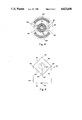
- FIG. 2 is a top end view taken along line 2--2 of FIG. 1 to illustrate a transducer member of the diaphragm transducer;
- FIG. 3 is a side view of the transducer member taken along the direction of line 3--3 in FIG. 2;
- FIG. 4 is a view taken in the same direction as FIG. 2 illustrating the placement of strain gauges mounted on a diaphragm of the transducer member;
- FIG. 5 is a view of a circuit that illustrates the manner in which the strain gauges of the diaphragm transducer are connected to measure loading.
- a diaphragm transducer for sensing loading in accordance with the present invention is indicated generally by 10 and includes a bolt 12 illustrated as connecting two members 14 and 16 with the loading of this connection being sensed by the transducer as is hereinafter more fully described.
- Bolt 12 has a head 18 and a shank 20 that extends from the head with a smaller size in accordance with the conventional construction of bolts.
- the bolt head 18 has a seat surface 22 that engages the one member 14 and the shank 20 has a threaded end 24 that is threaded into a threaded hole in the other member 16 in order to secure the connection between the members.
- a transducer hole 26 formed in the bolt 12 has a head portion 28 located within the bolt head 18 and a shank portion 30 located within the bolt shank 20.
- the head portion 28 of bolt hole 26 is larger than its shank portion 30, which may be provided by any type of drilling or other machining operation performed on a conventional bolt.
- Transducer 10 shown in FIG. 1 also includes a transducer member 32 received within the bolt hole 26 and having a diaphragm 34 fixedly mounted within the head portion 28 of the bolt hole as in hereinafter more fully described.
- the transducer member 32 also includes a stem 36 that extends from the diaphragm 34 into the shank portion 30 of the bolt hole 26 and has a distal end 38 fixedly secured to the bolt.
- at least one strain gauge on the diaphragm 34 senses deflection thereof as the bolt is loaded so as to thereby measure the loading of the bolt.
- the construction of the transducer 10 illustrated in FIG. 1 can be utilized to sense loading of smaller bolts than heretofore possible due to the manner in which the larger diaphragm 34 is located within the bolt head 18 and the smaller stem 36 is located within the smaller shank 20. Also, both tension and compression of the bolt 12 can be sensed due to the construction of the transducer 10 which restrains both the diaphragm 34 and the distal end 38 of the stem 36.
- the diaphragm transducer 10 has the diaphragm 34 and the stem 36 of the transducer member 32 integral with each other.
- This integral construction of the transducer member 32 is preferably provided by a machining operation from a single piece of metal which is of the same composition as the bolt 12 with which the transducer member 32 is utilized so as to have the same rate of thermal expansion such that no deflection of the diaphragm takes place along the axial direction of the bolt as the temperature changes.
- the transducer member 32 will also be machined from steel with its integral construction; it should be noted that steel alloys have generally the same rate of thermal expansion such that it is not necessary to manufacture the transducer member 32 from different types of steel when different compositions of steel bolts are utilized. Furthermore, if the bolt 12 is made from aluminum or another metal, the transducer member 32 is likewise machined from aluminum or the other metal in order to have the same composition and thus the same rate of thermal expansion.
- the bolt 12 is provided with a seat 40 located within the head portion 28 of the bolt hole 26 in a concentric relationship with the central axis of the bolt.
- a retainer 42 of the transducer clamps the diaphragm 34 against the bolt seat 40 to provide its fixed relationship within the head portion 28 of the bolt hole 26.
- the bolt hole 26 includes an undercut 44 of an annular shape that surrounds the stem 36 of the transducer member so as to provide space to permit the diaphragm to flex without being inhibited by the bolt during such flexing.
- the head portion 28 of bolt hole 26 includes an annular counterbore 46 that receives a connector 48 which has diaphragm strain gauge connections 49 for connecting the strain gauges used in the load sensing as is hereinafter more fully described.
- the diaphragm 34 has a periphery including a rim 50 that extends axially with respect to the axis of the stem 36 of transducer member 32 and preferably has an annular shape whose lower surface 52 (FIG. 3) seats against the bolt seat 40 shown in FIG. 1 and whose upper surface 54 (FIG. 3) is engaged by the retainer 42 shown in FIG. 1.
- This retainer 42 is preferably a locking ring having a press fit into the head portion 28 of bolt hole 26 to cooperate with the bolt seat 40 in clamping the diaphragm rim 50.
- Such clamping of the diaphragm rim 50 causes the diaphragm 34 to flex with an S-shaped curvature in a radial direction between the rim 50 and the center of the diaphragm 34 in a manner that facilitates the strain gauge reading of the diaphragm deflection upon bolt loading.
- a suitable adhesive 56 is also preferably utilized to cooperate with the press fit in securing the locking ring retainer 42 to the bolt head 18 within the head portion 28 of the bolt hole 26.
- the distal end 38 of the stem 36 of transducer member 32 includes threads 58 and, as shown in FIG. 1, the shank portion 30 of the bolt hole 26 includes an end 60 having threads 62 that receive the stem threads 58 in order to secure the stem 36 with respect to the bolt.
- the diaphragm rim 50 includes formations 64 for torquing the stem threads 58 into the bolt hole threads 62 shown in FIG. 1 to secure the stem end 38 and also seat the lower surface of the diaphragm rim 50 against the bolt seat 40.
- These rim formations 64 are preferably located at diametrically opposite locations as shown in FIG. 2 so as to permit the use of a screwdriver to provide the torquing that provides the threaded assembly of the transducer member 32 to the bolt.
- the transducer member 32 has a diaphragm diameter D, a diaphragm thickness T, and an effective stem length L that deflects upon loading.
- This effective stem length L includes the entire length L1 of the stem 36 between the diaphragm 34 and its threaded distal end 38 and a portion of the length L2 of the threaded distal end 38 of the stem. More specifically, the effective length L includes approximately 30% of the length L2 when the latter dimension is about twice the diameter of the threaded end 38. When the length L2 is less than twice the diameter of the threaded end 38, the effective length will be slightly greater than 30% of its length.
- the portion of the length L2 that is added to the stem length L1 to provide the effective length L is no greater than the 30% added when the length L2 is twice the diameter of the threaded end.
- the dimensions D, T, and L are selected to provide a maximum diaphragm deflection of about 1/3 T when the bolt 12 is loaded to its proof load which is the maximum tension load the bolt can withstand without incurring a permanent deformation.
- One preferred embodiment of the transducer 10 which has been found to function satisfactorily has a diaphragm diameter D of 0.2 inches, a diaphragm thickness T of 0.015 plus or minus 0.001 inches, a stem length L1 of 0.22 inches, a threaded end length L2 of 0.1 inches, and an effective stem length L of about 0.25 inches.
- the transducer member 32 of this preferred embodiment also has a rim wall thickness T1 of about 0.0225 to 0.0245 inches, a rim wall height H of about 0.07 inches, and a stem diameter D1 of about 0.045 to 0.055 inches as well as having its threaded end 38 provided with a 4-40 thread.
- the steel from which the transducer member 32 is machined is a 4130 alloy with a hardness of 34 on the Rockwell C scale.
- the diaphragm 34 is provided with four strain gauges 66, 68, 70, and 72.
- the two strain gauges 66 and 68 measure radial deformation adjacent the periphery of the diaphragm 34 where the radial deformation is the greatest, while the two strain gauges 70 and 72 measure circumferential deformation adjacent the center of the diaphragm where the circumferential deformation is the greatest. As shown in FIG.
- these strain gauges 66, 68, 60 and 72 are connected in a Wheatstone bridge 74 which has a soldered junction 76 connecting the strain gauges 66 and 70, a soldered junction 78 connecting the strain gauges 68 and 70, a soldered junction 80 connecting the strain gauges 66 and 72, and a soldered junction 82 connecting the strain gauges 68 and 72.
- a control circuit 84 includes a source of power 86 and a switch 88 for energizing the Wheatstone bridge 74.
- the Wheatstone bridge includes a meter 90 and switch 92 for use in reading the bridge output that reflects the loading of the bolt with compensation for temperature changes and for bending of the bolt shank.
- the soldered junctions 76, 78, 80, and 82 are connected by the connections 49 shown in FIG. 1 to the connector 48 which facilitates connection to instrumentation for reading the bolt loading.
Landscapes
- Engineering & Computer Science (AREA)
- General Engineering & Computer Science (AREA)
- Physics & Mathematics (AREA)
- General Physics & Mathematics (AREA)
- Mechanical Engineering (AREA)
- Measuring Fluid Pressure (AREA)
Abstract
Description
Claims (12)
Priority Applications (1)
| Application Number | Priority Date | Filing Date | Title |
|---|---|---|---|
| US07/210,723 US4823606A (en) | 1988-06-23 | 1988-06-23 | Diaphragm transducer for sensing loading |
Applications Claiming Priority (1)
| Application Number | Priority Date | Filing Date | Title |
|---|---|---|---|
| US07/210,723 US4823606A (en) | 1988-06-23 | 1988-06-23 | Diaphragm transducer for sensing loading |
Publications (1)
| Publication Number | Publication Date |
|---|---|
| US4823606A true US4823606A (en) | 1989-04-25 |
Family
ID=22784025
Family Applications (1)
| Application Number | Title | Priority Date | Filing Date |
|---|---|---|---|
| US07/210,723 Expired - Fee Related US4823606A (en) | 1988-06-23 | 1988-06-23 | Diaphragm transducer for sensing loading |
Country Status (1)
| Country | Link |
|---|---|
| US (1) | US4823606A (en) |
Cited By (33)
| Publication number | Priority date | Publication date | Assignee | Title |
|---|---|---|---|---|
| US5211061A (en) * | 1991-07-16 | 1993-05-18 | Goodwin Jerry J | Bolt clamping force sensor and clamping force validation method |
| EP0694772A1 (en) * | 1994-07-26 | 1996-01-31 | Smep (S.A.) | Fastener equipped with a device for the initial adjustment and surveillance a posteriori of the elongation |
| US5650576A (en) * | 1993-05-10 | 1997-07-22 | Vae Aktiengesellschaft | Device for measuring switching force |
| US5717143A (en) * | 1996-06-14 | 1998-02-10 | Electric Power Research Institute, Inc. | Apparatus for illustrating bolt preloads |
| US6044711A (en) * | 1997-01-10 | 2000-04-04 | Psi-Tronix, Inc. | Force sensing apparatus |
| US20030145657A1 (en) * | 2000-02-07 | 2003-08-07 | Paul Engler | Test device for determining the friction and prestress values of screwed connections |
| US20040208725A1 (en) * | 2001-08-24 | 2004-10-21 | Antonius Bader | Device with a screw plug and a range of devices |
| US6951137B2 (en) | 2001-07-02 | 2005-10-04 | Alliant Techsystems, Inc. | Method and apparatus for measuring bending in a pin member |
| US20060272141A1 (en) * | 2003-05-13 | 2006-12-07 | Dickory Rudduck | Assembly and disassembly method, system, and component |
| US20070007955A1 (en) * | 2005-06-22 | 2007-01-11 | Goldfine Neil J | Fastener and fitting based sensing methods |
| US20070017295A1 (en) * | 2005-07-19 | 2007-01-25 | Hiroyuki Ohta | Bolt with function of measuring strain |
| US20070039396A1 (en) * | 2005-08-22 | 2007-02-22 | Honeywell International Inc. | Torque sensor packaging systems and methods |
| US20080001015A1 (en) * | 2006-06-14 | 2008-01-03 | Ching-Fong Hsieh | Capstan |
| US20080047353A1 (en) * | 2006-08-24 | 2008-02-28 | Clark Ronald C | Method and apparatus for indicating a load |
| US20080126383A1 (en) * | 2006-09-11 | 2008-05-29 | Tetra Technologies, Inc. | System and method for predicting compatibility of fluids with metals |
| US20080202225A1 (en) * | 2004-07-07 | 2008-08-28 | Michael Munz | Dynamometer Element |
| US20080253858A1 (en) * | 2007-04-12 | 2008-10-16 | Chih-Ching Hsieh | Screwing device with function of twisting force measurement |
| US20080258720A1 (en) * | 2003-05-23 | 2008-10-23 | Jentek Sensors, Inc. | Hybrid wound/etched winding constructs for scanning and monitoring |
| US20090049930A1 (en) * | 2005-05-19 | 2009-02-26 | Takaaki Ogawa | Strain detector |
| US20090107260A1 (en) * | 2007-10-24 | 2009-04-30 | Thaddeus Schroeder | Magnetostrictive strain sensor with single piece sensor cavity |
| US7526964B2 (en) * | 2002-01-25 | 2009-05-05 | Jentek Sensors, Inc. | Applied and residual stress measurements using magnetic field sensors |
| US20090301383A1 (en) * | 2006-08-24 | 2009-12-10 | Clarke Ronald C | Indicating fastener loading |
| US20100077872A1 (en) * | 2008-10-01 | 2010-04-01 | Chih-Ching Hsieh | Fixing Element That Detects Deformations |
| US7994901B2 (en) | 2008-02-18 | 2011-08-09 | Tag Blue L.L.C. | Lug stud and lug nut monitoring system, method, and components therefor |
| DE202012100054U1 (en) | 2011-01-19 | 2012-04-25 | Kabo Tool Company | Screw with load sensor |
| US20120097490A1 (en) * | 2008-09-23 | 2012-04-26 | Robert Bosch Gmbh | Retaining Bolt |
| US20130180343A1 (en) * | 2011-11-26 | 2013-07-18 | Tecsis Gmbh | Force-sensing device for measuring a traction-and/or pressure force load in structure |
| US20140283624A1 (en) * | 2011-08-31 | 2014-09-25 | Fasteners Solutions Limited | Load-indicating device |
| US20150247521A1 (en) * | 2014-03-03 | 2015-09-03 | Kabo Tool Company | Dust proof structure for stress-sensible screw |
| WO2016015092A1 (en) * | 2014-07-30 | 2016-02-04 | Integrity Engineering Solutions Pty Ltd | Fasteners |
| CN109632006A (en) * | 2019-01-11 | 2019-04-16 | 重庆大学 | A kind of intelligent wireless bolt and on-line monitoring system |
| CN109738106A (en) * | 2019-01-11 | 2019-05-10 | 重庆大学 | A kind of intelligent wireless bolt that can detect bolt pretightening and bent screws state |
| TWI710714B (en) * | 2019-04-25 | 2020-11-21 | 倢通科技股份有限公司 | Bolt sensing structure |
Citations (8)
| Publication number | Priority date | Publication date | Assignee | Title |
|---|---|---|---|---|
| US2848892A (en) * | 1954-10-21 | 1958-08-26 | Hoffman Donald Bernard | Elevator load transducer |
| US2925576A (en) * | 1955-12-19 | 1960-02-16 | Sperry Rand Corp | Strain-sensitive electrical pick-up device |
| US3161844A (en) * | 1961-12-05 | 1964-12-15 | Fairchild Camera Instr Co | Semiconductor beam strain gauge |
| US3493912A (en) * | 1966-10-25 | 1970-02-03 | Ether Eng Ltd | Strain responsive transducer means of the diaphragm type |
| US4267725A (en) * | 1979-05-22 | 1981-05-19 | Roth Jac M | Arrangement for registering loads |
| US4429579A (en) * | 1981-10-26 | 1984-02-07 | Helm Instrument Co., Inc. | Tie rod tension sensor |
| US4553124A (en) * | 1983-09-16 | 1985-11-12 | Carron & Company | Strain gauge transducer assembly |
| US4630490A (en) * | 1985-07-12 | 1986-12-23 | Carron & Company | Compression strain gauge transducer assembly |
-
1988
- 1988-06-23 US US07/210,723 patent/US4823606A/en not_active Expired - Fee Related
Patent Citations (8)
| Publication number | Priority date | Publication date | Assignee | Title |
|---|---|---|---|---|
| US2848892A (en) * | 1954-10-21 | 1958-08-26 | Hoffman Donald Bernard | Elevator load transducer |
| US2925576A (en) * | 1955-12-19 | 1960-02-16 | Sperry Rand Corp | Strain-sensitive electrical pick-up device |
| US3161844A (en) * | 1961-12-05 | 1964-12-15 | Fairchild Camera Instr Co | Semiconductor beam strain gauge |
| US3493912A (en) * | 1966-10-25 | 1970-02-03 | Ether Eng Ltd | Strain responsive transducer means of the diaphragm type |
| US4267725A (en) * | 1979-05-22 | 1981-05-19 | Roth Jac M | Arrangement for registering loads |
| US4429579A (en) * | 1981-10-26 | 1984-02-07 | Helm Instrument Co., Inc. | Tie rod tension sensor |
| US4553124A (en) * | 1983-09-16 | 1985-11-12 | Carron & Company | Strain gauge transducer assembly |
| US4630490A (en) * | 1985-07-12 | 1986-12-23 | Carron & Company | Compression strain gauge transducer assembly |
Cited By (57)
| Publication number | Priority date | Publication date | Assignee | Title |
|---|---|---|---|---|
| US5211061A (en) * | 1991-07-16 | 1993-05-18 | Goodwin Jerry J | Bolt clamping force sensor and clamping force validation method |
| US5650576A (en) * | 1993-05-10 | 1997-07-22 | Vae Aktiengesellschaft | Device for measuring switching force |
| EP0694772A1 (en) * | 1994-07-26 | 1996-01-31 | Smep (S.A.) | Fastener equipped with a device for the initial adjustment and surveillance a posteriori of the elongation |
| FR2723197A1 (en) * | 1994-07-26 | 1996-02-02 | Smep Sa | HARDWARE ELEMENTS EQUIPPED WITH AN INITIAL ADJUSTMENT AND POST-DIFFERENTIAL MONITORING DEVICE |
| US5717143A (en) * | 1996-06-14 | 1998-02-10 | Electric Power Research Institute, Inc. | Apparatus for illustrating bolt preloads |
| US6044711A (en) * | 1997-01-10 | 2000-04-04 | Psi-Tronix, Inc. | Force sensing apparatus |
| US6810747B2 (en) * | 2000-02-07 | 2004-11-02 | Kistler Holding Ag | Test device for determining the friction and prestress values of screwed connections |
| US20030145657A1 (en) * | 2000-02-07 | 2003-08-07 | Paul Engler | Test device for determining the friction and prestress values of screwed connections |
| US6951137B2 (en) | 2001-07-02 | 2005-10-04 | Alliant Techsystems, Inc. | Method and apparatus for measuring bending in a pin member |
| US20040208725A1 (en) * | 2001-08-24 | 2004-10-21 | Antonius Bader | Device with a screw plug and a range of devices |
| US7624618B2 (en) * | 2001-08-24 | 2009-12-01 | Sew-Eurodrive Gmbh & Co. Kg | Device with a screw plug and a range of devices |
| US7526964B2 (en) * | 2002-01-25 | 2009-05-05 | Jentek Sensors, Inc. | Applied and residual stress measurements using magnetic field sensors |
| US9186760B2 (en) * | 2003-05-13 | 2015-11-17 | Telezygology, Inc. | Assembly and disassembly method, system, and component |
| US20060272141A1 (en) * | 2003-05-13 | 2006-12-07 | Dickory Rudduck | Assembly and disassembly method, system, and component |
| US7518360B2 (en) | 2003-05-23 | 2009-04-14 | Jentek Sensors, Inc. | Hybrid wound/etched winding constructs for scanning and monitoring |
| US20080258720A1 (en) * | 2003-05-23 | 2008-10-23 | Jentek Sensors, Inc. | Hybrid wound/etched winding constructs for scanning and monitoring |
| US20080202225A1 (en) * | 2004-07-07 | 2008-08-28 | Michael Munz | Dynamometer Element |
| US7819017B2 (en) * | 2004-07-07 | 2010-10-26 | Robert Bosch Gmbh | Dynamometer element |
| US7836774B2 (en) * | 2005-05-19 | 2010-11-23 | Panasonic Corporation | Strain detector having a column-shaped strain generator |
| US20090049930A1 (en) * | 2005-05-19 | 2009-02-26 | Takaaki Ogawa | Strain detector |
| US20070007955A1 (en) * | 2005-06-22 | 2007-01-11 | Goldfine Neil J | Fastener and fitting based sensing methods |
| US7528598B2 (en) | 2005-06-22 | 2009-05-05 | Jentek Sensors, Inc. | Fastener and fitting based sensing methods |
| US7293466B2 (en) * | 2005-07-19 | 2007-11-13 | Hitachi, Ltd. | Bolt with function of measuring strain |
| US20070017295A1 (en) * | 2005-07-19 | 2007-01-25 | Hiroyuki Ohta | Bolt with function of measuring strain |
| US7395724B2 (en) | 2005-08-22 | 2008-07-08 | Honeywell International Inc. | Torque sensor packaging systems and methods |
| WO2007024857A3 (en) * | 2005-08-22 | 2007-05-03 | Honeywell Int Inc | Torque sensor packaging systems and methods |
| WO2007024857A2 (en) * | 2005-08-22 | 2007-03-01 | Honeywell International Inc. | Torque sensor packaging systems and methods |
| US20070039396A1 (en) * | 2005-08-22 | 2007-02-22 | Honeywell International Inc. | Torque sensor packaging systems and methods |
| US20080001015A1 (en) * | 2006-06-14 | 2008-01-03 | Ching-Fong Hsieh | Capstan |
| US7520174B2 (en) | 2006-08-24 | 2009-04-21 | Ronald C. Clarke | Method and apparatus for indicating a load |
| US20080047353A1 (en) * | 2006-08-24 | 2008-02-28 | Clark Ronald C | Method and apparatus for indicating a load |
| US20090301383A1 (en) * | 2006-08-24 | 2009-12-10 | Clarke Ronald C | Indicating fastener loading |
| US8024979B2 (en) | 2006-08-24 | 2011-09-27 | Clarke Ronald C | Indicating fastener loading |
| DE202007019543U1 (en) | 2006-08-24 | 2013-06-18 | Ronald C. Clarke | Load display device |
| US7519481B2 (en) * | 2006-09-11 | 2009-04-14 | Tetra Tech | System and method for predicting compatibility of fluids with metals |
| US20080126383A1 (en) * | 2006-09-11 | 2008-05-29 | Tetra Technologies, Inc. | System and method for predicting compatibility of fluids with metals |
| US20080253858A1 (en) * | 2007-04-12 | 2008-10-16 | Chih-Ching Hsieh | Screwing device with function of twisting force measurement |
| US20090107260A1 (en) * | 2007-10-24 | 2009-04-30 | Thaddeus Schroeder | Magnetostrictive strain sensor with single piece sensor cavity |
| US7994901B2 (en) | 2008-02-18 | 2011-08-09 | Tag Blue L.L.C. | Lug stud and lug nut monitoring system, method, and components therefor |
| US20120097490A1 (en) * | 2008-09-23 | 2012-04-26 | Robert Bosch Gmbh | Retaining Bolt |
| US20100077872A1 (en) * | 2008-10-01 | 2010-04-01 | Chih-Ching Hsieh | Fixing Element That Detects Deformations |
| CN102606593A (en) * | 2011-01-19 | 2012-07-25 | 优钢机械股份有限公司 | Screw with stress detection structure |
| DE202012100054U1 (en) | 2011-01-19 | 2012-04-25 | Kabo Tool Company | Screw with load sensor |
| US20140283624A1 (en) * | 2011-08-31 | 2014-09-25 | Fasteners Solutions Limited | Load-indicating device |
| US9612172B2 (en) * | 2011-08-31 | 2017-04-04 | Tenscon Limited | Load-indicating device |
| US20130180343A1 (en) * | 2011-11-26 | 2013-07-18 | Tecsis Gmbh | Force-sensing device for measuring a traction-and/or pressure force load in structure |
| US8887585B2 (en) * | 2011-11-26 | 2014-11-18 | Tecsis Gmbh | Force-sensing device for measuring a traction-and/or pressure force load in structure |
| US20150247521A1 (en) * | 2014-03-03 | 2015-09-03 | Kabo Tool Company | Dust proof structure for stress-sensible screw |
| US9488212B2 (en) * | 2014-03-03 | 2016-11-08 | Kabo Tool Company | Dust proof structure for stress-sensible screw |
| WO2016015092A1 (en) * | 2014-07-30 | 2016-02-04 | Integrity Engineering Solutions Pty Ltd | Fasteners |
| CN106795904A (en) * | 2014-07-30 | 2017-05-31 | 因特格瑞提工程方案有限公司 | fastener |
| US10316881B2 (en) | 2014-07-30 | 2019-06-11 | Integrity Engineering Solutions Pty Ltd | Fasteners |
| AU2015296888B2 (en) * | 2014-07-30 | 2019-08-01 | Integrity Engineering Solutions Pty Ltd | Fasteners |
| CN106795904B (en) * | 2014-07-30 | 2019-09-17 | 因特格瑞提工程方案有限公司 | Fastener |
| CN109632006A (en) * | 2019-01-11 | 2019-04-16 | 重庆大学 | A kind of intelligent wireless bolt and on-line monitoring system |
| CN109738106A (en) * | 2019-01-11 | 2019-05-10 | 重庆大学 | A kind of intelligent wireless bolt that can detect bolt pretightening and bent screws state |
| TWI710714B (en) * | 2019-04-25 | 2020-11-21 | 倢通科技股份有限公司 | Bolt sensing structure |
Similar Documents
| Publication | Publication Date | Title |
|---|---|---|
| US4823606A (en) | Diaphragm transducer for sensing loading | |
| US4553124A (en) | Strain gauge transducer assembly | |
| US4630490A (en) | Compression strain gauge transducer assembly | |
| US4519254A (en) | High pressure transducer | |
| US3174386A (en) | Indicating washer | |
| US6606912B2 (en) | Structure or construction for mounting a pressure detector | |
| US10345180B2 (en) | Pressure sensor | |
| CN101622462B (en) | Method and apparatus for indicating a load | |
| US4928531A (en) | Fastening device for the attaching of an electric transmitter | |
| US3323403A (en) | Pre-load indicating washer | |
| EP1393929B1 (en) | Torque angle limiting wheelnut | |
| JP3841438B2 (en) | Method and apparatus for displaying load | |
| EP1118849A1 (en) | High-pressure sensor with one or two threaded stems bearing multi-pad sensor chips | |
| EP1265061B1 (en) | A high pressure sensor with separate pressure port and housing and method for making the same | |
| US5179861A (en) | Diaphragm type pressure sensor | |
| US5271700A (en) | Fixing member | |
| US4715231A (en) | Maximum pressure indicator | |
| JPS63167233A (en) | Axial force control method | |
| US6453751B1 (en) | Device for measuring pulling-in force | |
| JP3365476B2 (en) | Pressure sensor | |
| JPH024725Y2 (en) | ||
| CA2325557A1 (en) | Apparatus and method for attaching a load indicating device to a fastener | |
| KR200226725Y1 (en) | Attachment of Bourdon tube pressure gauge | |
| SU1679077A1 (en) | Device for measuring axial force in fastening parts | |
| JP2964068B2 (en) | Evaluation method of bolt tightening force |
Legal Events
| Date | Code | Title | Description |
|---|---|---|---|
| AS | Assignment |
Owner name: CARRON & COMPANY, INKSTER, MICHIGAN A CORP. OF MI Free format text: ASSIGNMENT OF ASSIGNORS INTEREST.;ASSIGNOR:MALICKI, RAYMOND W.;REEL/FRAME:004911/0734 Effective date: 19880615 Owner name: CARRON & COMPANY,MICHIGAN Free format text: ASSIGNMENT OF ASSIGNORS INTEREST;ASSIGNOR:MALICKI, RAYMOND W.;REEL/FRAME:004911/0734 Effective date: 19880615 |
|
| CC | Certificate of correction | ||
| FEPP | Fee payment procedure |
Free format text: PAYOR NUMBER ASSIGNED (ORIGINAL EVENT CODE: ASPN); ENTITY STATUS OF PATENT OWNER: LARGE ENTITY |
|
| FPAY | Fee payment |
Year of fee payment: 4 |
|
| SULP | Surcharge for late payment | ||
| FPAY | Fee payment |
Year of fee payment: 8 |
|
| AS | Assignment |
Owner name: NATIONAL CANADA FINANCE CORPORATION, OHIO Free format text: ASSIGNMENT OF ASSIGNORS INTEREST;ASSIGNOR:AMERICAN COMMERCIAL INDUSTRIES, INC.;REEL/FRAME:008296/0200 Effective date: 19960531 |
|
| AS | Assignment |
Owner name: AMERICAN COMMERCIAL INDUSTRIES, INC., OHIO Free format text: ASSIGNMENT OF ASSIGNORS INTEREST;ASSIGNOR:CARRON & COMPANY;REEL/FRAME:008251/0392 Effective date: 19961219 |
|
| AS | Assignment |
Owner name: CARRON INDUSTRIES, LLC, MICHIGAN Free format text: ASSIGNMENT OF ASSIGNORS INTEREST;ASSIGNOR:CARRON & COMPANY;REEL/FRAME:010247/0562 Effective date: 19991001 |
|
| AS | Assignment |
Owner name: BANK ONE, MICHIGAN, MICHIGAN Free format text: ASSIGNMENT AND SECURITY AGREEMENT;ASSIGNOR:CARRON INDUSTRIES, INC.;REEL/FRAME:010360/0511 Effective date: 19990927 |
|
| REMI | Maintenance fee reminder mailed | ||
| LAPS | Lapse for failure to pay maintenance fees | ||
| FP | Lapsed due to failure to pay maintenance fee |
Effective date: 20010425 |
|
| STCH | Information on status: patent discontinuation |
Free format text: PATENT EXPIRED DUE TO NONPAYMENT OF MAINTENANCE FEES UNDER 37 CFR 1.362 |