EP1393929B1 - Torque angle limiting wheelnut - Google Patents
Torque angle limiting wheelnut Download PDFInfo
- Publication number
- EP1393929B1 EP1393929B1 EP03025087A EP03025087A EP1393929B1 EP 1393929 B1 EP1393929 B1 EP 1393929B1 EP 03025087 A EP03025087 A EP 03025087A EP 03025087 A EP03025087 A EP 03025087A EP 1393929 B1 EP1393929 B1 EP 1393929B1
- Authority
- EP
- European Patent Office
- Prior art keywords
- wheelnut
- wheel
- seat
- nut
- conical
- Prior art date
- Legal status (The legal status is an assumption and is not a legal conclusion. Google has not performed a legal analysis and makes no representation as to the accuracy of the status listed.)
- Expired - Lifetime
Links
- 229910052751 metal Inorganic materials 0.000 description 7
- 239000002184 metal Substances 0.000 description 7
- 229910052782 aluminium Inorganic materials 0.000 description 6
- XAGFODPZIPBFFR-UHFFFAOYSA-N aluminium Chemical compound [Al] XAGFODPZIPBFFR-UHFFFAOYSA-N 0.000 description 6
- 229910000831 Steel Inorganic materials 0.000 description 3
- 238000000034 method Methods 0.000 description 3
- 239000010959 steel Substances 0.000 description 3
- 229910000838 Al alloy Inorganic materials 0.000 description 1
- 230000002411 adverse Effects 0.000 description 1
- 238000000418 atomic force spectrum Methods 0.000 description 1
- 230000006835 compression Effects 0.000 description 1
- 238000007906 compression Methods 0.000 description 1
- 238000005259 measurement Methods 0.000 description 1
- 150000002739 metals Chemical class 0.000 description 1
Images

Classifications
-
- F—MECHANICAL ENGINEERING; LIGHTING; HEATING; WEAPONS; BLASTING
- F16—ENGINEERING ELEMENTS AND UNITS; GENERAL MEASURES FOR PRODUCING AND MAINTAINING EFFECTIVE FUNCTIONING OF MACHINES OR INSTALLATIONS; THERMAL INSULATION IN GENERAL
- F16B—DEVICES FOR FASTENING OR SECURING CONSTRUCTIONAL ELEMENTS OR MACHINE PARTS TOGETHER, e.g. NAILS, BOLTS, CIRCLIPS, CLAMPS, CLIPS OR WEDGES; JOINTS OR JOINTING
- F16B37/00—Nuts or like thread-engaging members
- F16B37/14—Cap nuts; Nut caps or bolt caps
-
- B—PERFORMING OPERATIONS; TRANSPORTING
- B60—VEHICLES IN GENERAL
- B60B—VEHICLE WHEELS; CASTORS; AXLES FOR WHEELS OR CASTORS; INCREASING WHEEL ADHESION
- B60B3/00—Disc wheels, i.e. wheels with load-supporting disc body
- B60B3/14—Attaching disc body to hub ; Wheel adapters
- B60B3/16—Attaching disc body to hub ; Wheel adapters by bolts or the like
-
- F—MECHANICAL ENGINEERING; LIGHTING; HEATING; WEAPONS; BLASTING
- F16—ENGINEERING ELEMENTS AND UNITS; GENERAL MEASURES FOR PRODUCING AND MAINTAINING EFFECTIVE FUNCTIONING OF MACHINES OR INSTALLATIONS; THERMAL INSULATION IN GENERAL
- F16B—DEVICES FOR FASTENING OR SECURING CONSTRUCTIONAL ELEMENTS OR MACHINE PARTS TOGETHER, e.g. NAILS, BOLTS, CIRCLIPS, CLAMPS, CLIPS OR WEDGES; JOINTS OR JOINTING
- F16B43/00—Washers or equivalent devices; Other devices for supporting bolt-heads or nuts
- F16B43/02—Washers or equivalent devices; Other devices for supporting bolt-heads or nuts with special provisions for engaging surfaces which are not perpendicular to a bolt axis or do not surround the bolt
Definitions
- This invention relates generally to wheelnuts and mounting wheels for the axles of motor vehicles. More particularly, the wheelnut of the combination of the invention is structured to prevent the nut from engaging the wheel with an overload that might cause deformation of the wheel, particularly, in cases where the wheel is made of a metal softer than steel such as aluminum.
- the majority of wheelnuts include a conical surface which engages the wheel and applies a clamping force to the wheel in response to torque.
- the defining characteristic of the majority of wheelnuts is the conical surface. This is the surface through which clamping forces are applied and also the means by which the wheel is centered in the final assembled position. Decades of application and testing has produced a body of engineering knowledge about wheel assembly. Modern wheel assembly methods and controls have been developed as a result of this empirical data.
- US-A-4382635 discloses a combination according to the preamble of claim 1.
- a certain minimum clamping force is specified for a wheel assembly and a method for determining that this criteria is met at assembly is necessary. In the laboratory this is accomplished with a special fixture and a load sensor that measures this force. In the assembly plant, no practical method of directly measuring this force exists, but torque and torque angle can be measured. An understanding of the relationship between torque and clamp load makes torque and torque angle an appropriate control measurement to ensure proper clamp load. Upper and lower limits are set for torque applied at assembly and torque angle is monitored to detect variance from the normal duration of the torque vs. tension force curve. Extreme variance from the defined norm can indicate a problem in the assembly that could compromise the assembly strength.
- This invention provides for a feature on the wheelnut that limits the amount of deformation in the wheel seat, likewise limiting the torque angle at assembly.
- a limiting feature in this invention is the provision of a stop surface on the wheelnut which is generally perpendicular to the axis of the nut and intersects the conical surface to thereby preclude the application of torque forces on the wheelnut that overload and deform the wheel in the case of wheels made of softer metals, such as aluminum.
- An embodiment of the invention is disclosed including this limiting stop surface which limits the clamping force that can be applied to the wheel when it is being mounted on the motor vehicle, and including the washer and cap as defined in claim 1.
- the wheelnut indicated generally at 10 in FIG. 2, comprises a metal body 12 having a longitudinal axis 14 and an axial aperture 16.
- the body 12 has ends 18 and 20 with a conical surface 22 at the inner end 18 and wrench flats 24 at the outer end 20.
- the wheelnut 10 is shown in FIG. 2 in a position clamping a motor vehicle wheel 26, only a portion of which is shown, against a conventional axle plate 28 secured to the axle in a motor vehicle (not shown).
- the wheel 26 is provided with a wheelnut seat surface 36 which is of conical shape corresponding to the shape of the conical surface 22.
- the wheel 26 is clamped against the plate 28 by a number of wheelnuts 10 on bolts carried by the axle plate 28, one of which is shown at 30 in FIG. 2.
- the wheel 26 has a number of openings 34, only one of which is shown in FIG. 2, which are telescoped over the bolts 30.
- Each opening 34 has a conical nut seat 36 which corresponds in shape to the conical surface 22 on the wheelnut 10.
- the wheelnut 10 is threaded onto the bolt 32 to a position in which the conical surface 22 seats on the seat 36.
- a torque force is applied to the wrench flats 24 so as to induce a clamping force on the wheel 26 at the seat surface 36 and by the conical surface 22 on the wheelnut 10.
- the wheel 26 is constructed of a metal that is softer than steel, such as aluminum, it is possible to overload the clamping force on the wheel with a conventional nut 35 shown in FIG. 1 in a normal wheel clamping position.
- the body 12 of the wheelnut 10 is provided with a flange 38 which has a stop surface 40 lying generally in a plane 42 which is generally perpendicular to the axis 14.
- a stop surface 40 lying generally in a plane 42 which is generally perpendicular to the axis 14.
- the prior art nut 3 5 is capable of deforming the wheel 26 by a high clamp force as shown in FIG. 7.
- the nut 35 has a conical surface 37 but no flange like the flange 38.
- the cylindrical band 39 above the surface 37 cannot stop the nut 35 from advancing into the surface 37.
- the clamping forces applied to the wheel 26 by the wheelnut 10 in response to a torque force on the wrench flats 24, is related to the included angle between the axis 14 and the conical surface 22.
- the desired clamping forces can be assured without danger of deformation of the soft metal wheel 26.
- the stop surface 40 In order for the stop surface 40 to be effective, it must intercept the conical surface 22. If the plane 42 is spaced from the conical surface, deformation of the wheel could take place prior to the stop surface 40 engages the wheel 26.
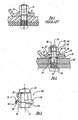
- FIGS. 3 and 5 show other embodiments of a wheelnut 10, whereby Fig. 3 discloses a wheelnut according to the invention. These embodiments are very similar to the embodiment shown in FIG. 2 and for these reasons, like numerals are used to designate like parts in the wheelnuts 10, 10a and 10b.
- the wheelnuts 10a and 10b differ from the wheelnut 10 described above in that each of the wheelnuts 10a and 10b utilizes a multi-piece body 50 consisting of an internally threaded member 52 which can be threaded on the bolt 30 and a washer or "wheel seat engaging" member 54.
- the washer 54 rotates freely around the axis 14.
- an external cap 56 holds the threaded member 52 and the washer 54 together.
- each of the 10a and 10b wheelnuts includes essential components of the wheelnut 10.
- each contains the conical surface 22, the flange 38 and the stop surface 40 which is perpendicular to the axis 14 and is in a plane which intersects the conical surface 22.
- the outer element 50 has an inclined lower surface 58 which is in surface-to-surface contact with a similar surface 60 on the outer end of the washer 54.
- a similar arrangement exists in the wheelnut 10b where the member and the washer 54 rotate freely relative to each other.
- this invention provides a wheelnut 10a which can effectively be used to attach wheels of soft metal, such as aluminum to motor vehicles without deforming the wheels. These soft metal wheels are in wide use now. This invention will permit further use of the aluminum wheels.
Description
- This invention relates generally to wheelnuts and mounting wheels for the axles of motor vehicles. More particularly, the wheelnut of the combination of the invention is structured to prevent the nut from engaging the wheel with an overload that might cause deformation of the wheel, particularly, in cases where the wheel is made of a metal softer than steel such as aluminum. The majority of wheelnuts include a conical surface which engages the wheel and applies a clamping force to the wheel in response to torque.
- The defining characteristic of the majority of wheelnuts is the conical surface. This is the surface through which clamping forces are applied and also the means by which the wheel is centered in the final assembled position. Decades of application and testing has produced a body of engineering knowledge about wheel assembly. Modern wheel assembly methods and controls have been developed as a result of this empirical data.
- US-A-4382635 discloses a combination according to the preamble of claim 1.
- A certain minimum clamping force is specified for a wheel assembly and a method for determining that this criteria is met at assembly is necessary. In the laboratory this is accomplished with a special fixture and a load sensor that measures this force. In the assembly plant, no practical method of directly measuring this force exists, but torque and torque angle can be measured. An understanding of the relationship between torque and clamp load makes torque and torque angle an appropriate control measurement to ensure proper clamp load. Upper and lower limits are set for torque applied at assembly and torque angle is monitored to detect variance from the normal duration of the torque vs. tension force curve. Extreme variance from the defined norm can indicate a problem in the assembly that could compromise the assembly strength.
- Occasionally very high clamp loads are generated (due to any of several variables) that can mean joint failure on an aluminum alloy wheel and no adverse consequence on a steel wheel. The failure is in the inability of the nut seat in the wheel to support this high clamp load, which is a consequence of the lower strength of aluminum. When this occurs, the nut drives through the wheel until clamp load is achieved. The magnitude of nut seat deformation can be judged by the torque angle value, the greater torque angle indicating greater nut seat deformation. Excessive deformation is considered to produce a faulty or unacceptable joint.
- This invention provides for a feature on the wheelnut that limits the amount of deformation in the wheel seat, likewise limiting the torque angle at assembly.
- A limiting feature in this invention is the provision of a stop surface on the wheelnut which is generally perpendicular to the axis of the nut and intersects the conical surface to thereby preclude the application of torque forces on the wheelnut that overload and deform the wheel in the case of wheels made of softer metals, such as aluminum. An embodiment of the invention is disclosed including this limiting stop surface which limits the clamping force that can be applied to the wheel when it is being mounted on the motor vehicle, and including the washer and cap as defined in claim 1.
- Further features, advantages and innovations will be apparent from the following drawings when taken in connection with the specification and claims.
-
- FIG. 1 illustrates a wheelnut that is relatively common in the prior art in assembly relation with a wheel and an axle mounting structure, with many of the elements shown in cross section for purposes of clarity;
- FIG. 2 is a cross sectional view like FIG. 1 showing an embodiment of a wheelnut which is not covered by the claims.
- FIG. 3 is a sectional view like FIG. 2 of the wheelnut of this invention, shown in the form of a wheelnut provided with a decorative cap;
- FIG. 4 is a top view of the wheelnut shown in FIG. 3;
- FIG. 5 is a vertical sectional view showing still another embodiment of this invention;
- FIG. 6 is a top view of the wheelnut shown in FIG. 5; and
- FIG. 7 is a cross sectional view like FIG. 1 showing the prior art wheelnut in a high clamp load position in which it is deforming the wheel.
- With reference to the drawing, the wheelnut, indicated generally at 10 in FIG. 2, comprises a
metal body 12 having alongitudinal axis 14 and an axial aperture 16. Thebody 12 has ends 18 and 20 with aconical surface 22 at theinner end 18 andwrench flats 24 at the outer end 20. - The
wheelnut 10 is shown in FIG. 2 in a position clamping amotor vehicle wheel 26, only a portion of which is shown, against aconventional axle plate 28 secured to the axle in a motor vehicle (not shown). Thewheel 26 is provided with awheelnut seat surface 36 which is of conical shape corresponding to the shape of theconical surface 22. - The
wheel 26 is clamped against theplate 28 by a number ofwheelnuts 10 on bolts carried by theaxle plate 28, one of which is shown at 30 in FIG. 2. Thewheel 26 has a number ofopenings 34, only one of which is shown in FIG. 2, which are telescoped over the bolts 30. Eachopening 34 has aconical nut seat 36 which corresponds in shape to theconical surface 22 on thewheelnut 10. Thewheelnut 10 is threaded onto the bolt 32 to a position in which theconical surface 22 seats on theseat 36. - A torque force is applied to the
wrench flats 24 so as to induce a clamping force on thewheel 26 at theseat surface 36 and by theconical surface 22 on thewheelnut 10. Assuming that thewheel 26 is constructed of a metal that is softer than steel, such as aluminum, it is possible to overload the clamping force on the wheel with aconventional nut 35 shown in FIG. 1 in a normal wheel clamping position. - In the
wheelnut 10 of this invention, thebody 12 of thewheelnut 10 is provided with aflange 38 which has astop surface 40 lying generally in aplane 42 which is generally perpendicular to theaxis 14. When thesurface 40 engages thewheel 26, the torque applied to thewrench flats 24 cannot advance the wheelnut further on the bolt 30. Thus, any chance of a coincident high clamp load excessively deforming thewheel 26 by thewheelnut 10 is positively precluded. - In contrast, the prior art nut 3 5 is capable of deforming the
wheel 26 by a high clamp force as shown in FIG. 7. Thenut 35 has aconical surface 37 but no flange like theflange 38. Thecylindrical band 39 above thesurface 37 cannot stop thenut 35 from advancing into thesurface 37. - The clamping forces applied to the
wheel 26 by thewheelnut 10 in response to a torque force on thewrench flats 24, is related to the included angle between theaxis 14 and theconical surface 22. The smaller this angle, the greater proportion of the torque forces are transmitted as a compression force on thewheel 26 parallel to theaxis 14. Thus, by providing the desirable angle on theconical surface 22 and the position of the flange in the direction of theaxis 14, the desired clamping forces can be assured without danger of deformation of thesoft metal wheel 26. In order for thestop surface 40 to be effective, it must intercept theconical surface 22. If theplane 42 is spaced from the conical surface, deformation of the wheel could take place prior to thestop surface 40 engages thewheel 26. - FIGS. 3 and 5 show other embodiments of a
wheelnut 10, whereby Fig. 3 discloses a wheelnut according to the invention. These embodiments are very similar to the embodiment shown in FIG. 2 and for these reasons, like numerals are used to designate like parts in thewheelnuts 10, 10a and 10b. The wheelnuts 10a and 10b differ from thewheelnut 10 described above in that each of the wheelnuts 10a and 10b utilizes amulti-piece body 50 consisting of an internally threadedmember 52 which can be threaded on the bolt 30 and a washer or "wheel seat engaging"member 54. Thewasher 54 rotates freely around theaxis 14. In the inventive combination including the wheelnut 10a, anexternal cap 56 holds the threadedmember 52 and thewasher 54 together. - Each of the 10a and 10b wheelnuts includes essential components of the
wheelnut 10. For example, each contains theconical surface 22, theflange 38 and thestop surface 40 which is perpendicular to theaxis 14 and is in a plane which intersects theconical surface 22. In the wheelnut 10a, theouter element 50 has an inclinedlower surface 58 which is in surface-to-surface contact with asimilar surface 60 on the outer end of thewasher 54. A similar arrangement exists in the wheelnut 10b where the member and thewasher 54 rotate freely relative to each other. The end faces 62 and 64 on the adjacent ends of the threadedmember 52 and thewasher 54, respectively, cooperate to transfer the torque forces on themember 52 to theconical surface 22 as clamping forces. - From the above disclosure it is evident that this invention provides a wheelnut 10a which can effectively be used to attach wheels of soft metal, such as aluminum to motor vehicles without deforming the wheels. These soft metal wheels are in wide use now. This invention will permit further use of the aluminum wheels.
Claims (3)
- A combination of a wheel (26) for a motor vehicle and a wheelnut (10a) of the type enabling securement of said wheel to a motor vehicle axle, said wheelnut including a body having a longitudinal axis, said nut body also having an axial threaded aperture and a pair of ends, a conical external surface (22) at one of said ends and wrench flats (24) at the other one of said ends facilitating the application of torque forces through said wrench flats to said nut body, said wheel having a nut seat surface (36) configured to receive said conical external surface in surface-to-surface engagement, so that a clamping force of increasing magnitude will be applied to said wheel at said seat in response to the application of torque force on said wheel nut characterized by means forming a stop surface (40) on said nut body extending radially outwardly of said conical surface engageable with said wheel in a position of said conical surface seated on said seat surface with force adequate to clamp said wheel prior to deformation of said wheel nut seat by said wheelnut in response to advance of said wheelnut against said seat, and wherein said wheelnut is comprised of multiple parts as follows:a) an internally threaded member; andb) a washer aligned with said threaded member and in end-to-end relation with said threaded member, said conical surface being located on said washer,c) a cap member mounted on said wheelnut so as to maintain said threaded member and said washer in said end-to-end relation.
- The combination set forth in claim 1 wherein said means forming said stop surface is a flange (38) on said body that is generally perpendicular to said axis.
- The combination set forth in claim 2 wherein said wrench flats, said conical surface and said flange ate integral parts of said wheelnut (10a).
Applications Claiming Priority (3)
| Application Number | Priority Date | Filing Date | Title |
|---|---|---|---|
| US09/031,396 US6102488A (en) | 1998-02-26 | 1998-02-26 | Torque angle limiting wheelnut |
| US31396 | 1998-02-26 | ||
| EP99102818A EP0938983B1 (en) | 1998-02-26 | 1999-02-26 | Torque angle limiting wheelnut |
Related Parent Applications (1)
| Application Number | Title | Priority Date | Filing Date |
|---|---|---|---|
| EP99102818A Division EP0938983B1 (en) | 1998-02-26 | 1999-02-26 | Torque angle limiting wheelnut |
Publications (3)
| Publication Number | Publication Date |
|---|---|
| EP1393929A2 EP1393929A2 (en) | 2004-03-03 |
| EP1393929A3 EP1393929A3 (en) | 2004-03-10 |
| EP1393929B1 true EP1393929B1 (en) | 2006-08-16 |
Family
ID=21859219
Family Applications (2)
| Application Number | Title | Priority Date | Filing Date |
|---|---|---|---|
| EP99102818A Expired - Lifetime EP0938983B1 (en) | 1998-02-26 | 1999-02-26 | Torque angle limiting wheelnut |
| EP03025087A Expired - Lifetime EP1393929B1 (en) | 1998-02-26 | 1999-02-26 | Torque angle limiting wheelnut |
Family Applications Before (1)
| Application Number | Title | Priority Date | Filing Date |
|---|---|---|---|
| EP99102818A Expired - Lifetime EP0938983B1 (en) | 1998-02-26 | 1999-02-26 | Torque angle limiting wheelnut |
Country Status (4)
| Country | Link |
|---|---|
| US (1) | US6102488A (en) |
| EP (2) | EP0938983B1 (en) |
| JP (1) | JP3902708B2 (en) |
| DE (2) | DE69914236T2 (en) |
Families Citing this family (18)
| Publication number | Priority date | Publication date | Assignee | Title |
|---|---|---|---|---|
| GB0024485D0 (en) * | 2000-10-06 | 2000-11-22 | Wheelsure Ltd | Wheel nut assembly |
| US6592314B1 (en) * | 2000-10-10 | 2003-07-15 | Industrial And Automotive Fasteners, Llc | Steel washer integral with nut/cap assembly |
| DE10054896B4 (en) * | 2000-11-06 | 2007-03-01 | Metallwarenfabrik Hermann Winker Gmbh & Co. Kg | Mother and process for its preparation |
| US6749386B2 (en) | 2001-08-20 | 2004-06-15 | Maclean-Fogg Company | Locking fastener assembly |
| AU2003223747A1 (en) * | 2002-04-26 | 2003-11-10 | Larry J. Wilson | Theft deterrent wheel fastener cap assembly and method |
| DE10256653A1 (en) * | 2002-12-04 | 2004-06-17 | Metallwarenfabrik Hermann Winker Gmbh & Co. Kg | Wheel nut |
| US20050204689A1 (en) * | 2004-02-19 | 2005-09-22 | Dejohn Louis Jr | Tapered nut kit and methods of use |
| US9635987B2 (en) * | 2008-02-22 | 2017-05-02 | Bemis Manufacturing Company | Hinge assembly for a toilet seat |
| US8281420B2 (en) * | 2008-02-22 | 2012-10-09 | Bemis Manufacturing Company | Hinge assembly for a toilet seat |
| FR2949858B1 (en) * | 2009-09-08 | 2012-03-23 | Snecma | EQUILIBRATION DEVICE AND METHOD |
| WO2011063099A1 (en) * | 2009-11-19 | 2011-05-26 | Maclean-Fogg Company | Fastener with improved torque bearing surface |
| US9206833B2 (en) | 2011-08-22 | 2015-12-08 | Mcgard Llc | Fastener with discrete head cap |
| US9340065B2 (en) * | 2014-03-05 | 2016-05-17 | GM Global Technology Operations LLC | Turn limited wheel lug nut and nut cap |
| US20160208844A1 (en) * | 2015-01-15 | 2016-07-21 | Maclean-Fogg Company | Crimped capped fastener |
| JP6260793B2 (en) * | 2015-02-06 | 2018-01-17 | Smc株式会社 | Connection device for fluid pressure equipment |
| EP3056748B1 (en) * | 2015-02-16 | 2018-09-12 | Lazzaro Groppo | Locking device made as a nut or bolt |
| DE102016206456B4 (en) * | 2016-04-18 | 2017-11-09 | Continental Automotive Gmbh | Combination comprising a housing and a flange, and arrangement |
| TWM563970U (en) * | 2018-04-19 | 2018-07-21 | 台灣固而美工業股份有限公司 | Locking member |
Family Cites Families (14)
| Publication number | Priority date | Publication date | Assignee | Title |
|---|---|---|---|---|
| US2432531A (en) * | 1945-05-12 | 1947-12-16 | Lyon George Albert | Wheel cover |
| US2954304A (en) * | 1956-07-11 | 1960-09-27 | Kroyer Karl Kristian Kobs | Process and apparatus for the production of starch syrup |
| US3138407A (en) * | 1963-02-25 | 1964-06-23 | Kelsey Hayes Co | Wheels |
| US3649079A (en) * | 1971-02-19 | 1972-03-14 | Int Mfg Co Inc | Automotive wheel structure |
| US3960047A (en) * | 1974-09-09 | 1976-06-01 | Cragar Industries, Inc. | Dual size lug nut |
| US4201110A (en) * | 1976-12-29 | 1980-05-06 | Toyota Jidosha Kogyo Kabushiki Kaisha | Hub nut with washer |
| US4382635A (en) * | 1981-02-13 | 1983-05-10 | General Motors Corporation | Plastic vehicle wheel cover |
| US4457560A (en) * | 1982-01-07 | 1984-07-03 | General Motors Corporation | Hubcap with improved retention structure |
| US4460300A (en) * | 1982-01-11 | 1984-07-17 | Illinois Tool Works Inc. | Fastener with head cap having a concealed edge |
| US4842339A (en) * | 1987-12-21 | 1989-06-27 | Ford Motor Company | Vehicle wheel cover and assembly |
| DE8813513U1 (en) * | 1988-10-27 | 1989-06-01 | Erich Neumayer Beteiligungs- Und Verwaltungsgesellschaft Mbh & Co Kg, 7613 Hausach, De | |
| US5163739A (en) * | 1991-09-03 | 1992-11-17 | General Motors Corporation | Wheel cover retention |
| US5772377A (en) * | 1997-05-08 | 1998-06-30 | Maclean-Fogg Company | Capped wheel fastener |
| FR2773743B1 (en) * | 1998-01-20 | 2000-04-07 | Peugeot | SCREW FOR FIXING A MOTOR VEHICLE WHEEL, LIGHT ALLOY OR SHEET |
-
1998
- 1998-02-26 US US09/031,396 patent/US6102488A/en not_active Expired - Fee Related
-
1999
- 1999-02-26 JP JP05138999A patent/JP3902708B2/en not_active Expired - Fee Related
- 1999-02-26 EP EP99102818A patent/EP0938983B1/en not_active Expired - Lifetime
- 1999-02-26 DE DE69914236T patent/DE69914236T2/en not_active Expired - Lifetime
- 1999-02-26 EP EP03025087A patent/EP1393929B1/en not_active Expired - Lifetime
- 1999-02-26 DE DE69932865T patent/DE69932865T2/en not_active Expired - Lifetime
Also Published As
| Publication number | Publication date |
|---|---|
| EP0938983A2 (en) | 1999-09-01 |
| JP3902708B2 (en) | 2007-04-11 |
| EP1393929A2 (en) | 2004-03-03 |
| EP1393929A3 (en) | 2004-03-10 |
| US6102488A (en) | 2000-08-15 |
| EP0938983B1 (en) | 2004-01-21 |
| JP2000027832A (en) | 2000-01-25 |
| DE69932865T2 (en) | 2007-07-12 |
| DE69932865D1 (en) | 2006-09-28 |
| EP0938983A3 (en) | 2001-10-31 |
| DE69914236D1 (en) | 2004-02-26 |
| DE69914236T2 (en) | 2004-11-04 |
Similar Documents
| Publication | Publication Date | Title |
|---|---|---|
| EP1393929B1 (en) | Torque angle limiting wheelnut | |
| US5386630A (en) | Process and tool for adjusting bearings | |
| US4527924A (en) | Ball joint for suspension of wheels | |
| US6089673A (en) | Vehicle wheel hub and bearing retention system and method for producing same | |
| US4969788A (en) | Nut with pressure ring | |
| US20050163589A1 (en) | Steel washer integral with nut/cap assembly | |
| US6170919B1 (en) | Vehicle suspension assembly | |
| JP2622192B2 (en) | Electrical contact nut | |
| US20090103974A1 (en) | Ball stud system for use within a ball joint | |
| US4708397A (en) | Motor vehicle wheel mounting means and method | |
| US5720086A (en) | Clamping collar | |
| US20040094927A1 (en) | Steering knuckle carrier-to-suspension arm pivotal connection and method of assembling and preloading the pivotal connection | |
| GB2051285A (en) | Wheel Nuts | |
| US4586580A (en) | Mounting for power-assisted master brake cylinder in an automotive vehicle | |
| EP1121254B1 (en) | A fastener device | |
| US4614451A (en) | Turnbuckle clamp assembly with orientation washer | |
| CA2129401C (en) | Split stud ring anchoring device | |
| JPH06235414A (en) | Spacer washer a bolt joint | |
| US5848801A (en) | Apparatus for fastening a gas bag | |
| US5735655A (en) | Lock nut assembly for vehicle axles | |
| EP0541488B1 (en) | Ball joint assembly and method of construction | |
| JPS6131549Y2 (en) | ||
| JPH0629042Y2 (en) | Mounting structure for damper bracket | |
| JPS602333Y2 (en) | Anti-rotation bolt | |
| US6299114B1 (en) | Assembling device with angular adjustment and method using same |
Legal Events
| Date | Code | Title | Description |
|---|---|---|---|
| PUAI | Public reference made under article 153(3) epc to a published international application that has entered the european phase |
Free format text: ORIGINAL CODE: 0009012 |
|
| PUAL | Search report despatched |
Free format text: ORIGINAL CODE: 0009013 |
|
| AC | Divisional application: reference to earlier application |
Ref document number: 0938983 Country of ref document: EP Kind code of ref document: P |
|
| AK | Designated contracting states |
Kind code of ref document: A2 Designated state(s): DE GB |
|
| AK | Designated contracting states |
Kind code of ref document: A3 Designated state(s): DE GB |
|
| RAP1 | Party data changed (applicant data changed or rights of an application transferred) |
Owner name: MACLEAN-FOGG GMBH |
|
| 17P | Request for examination filed |
Effective date: 20040903 |
|
| AKX | Designation fees paid |
Designated state(s): DE GB |
|
| RAP1 | Party data changed (applicant data changed or rights of an application transferred) |
Owner name: MACLEAN-FOGG GMBH |
|
| GRAP | Despatch of communication of intention to grant a patent |
Free format text: ORIGINAL CODE: EPIDOSNIGR1 |
|
| GRAS | Grant fee paid |
Free format text: ORIGINAL CODE: EPIDOSNIGR3 |
|
| GRAA | (expected) grant |
Free format text: ORIGINAL CODE: 0009210 |
|
| AC | Divisional application: reference to earlier application |
Ref document number: 0938983 Country of ref document: EP Kind code of ref document: P |
|
| AK | Designated contracting states |
Kind code of ref document: B1 Designated state(s): DE GB |
|
| REG | Reference to a national code |
Ref country code: GB Ref legal event code: FG4D |
|
| REF | Corresponds to: |
Ref document number: 69932865 Country of ref document: DE Date of ref document: 20060928 Kind code of ref document: P |
|
| PLBE | No opposition filed within time limit |
Free format text: ORIGINAL CODE: 0009261 |
|
| STAA | Information on the status of an ep patent application or granted ep patent |
Free format text: STATUS: NO OPPOSITION FILED WITHIN TIME LIMIT |
|
| 26N | No opposition filed |
Effective date: 20070518 |
|
| PGFP | Annual fee paid to national office [announced via postgrant information from national office to epo] |
Ref country code: GB Payment date: 20110831 Year of fee payment: 13 Ref country code: DE Payment date: 20110818 Year of fee payment: 13 |
|
| GBPC | Gb: european patent ceased through non-payment of renewal fee |
Effective date: 20120226 |
|
| REG | Reference to a national code |
Ref country code: DE Ref legal event code: R119 Ref document number: 69932865 Country of ref document: DE Effective date: 20120901 |
|
| PG25 | Lapsed in a contracting state [announced via postgrant information from national office to epo] |
Ref country code: GB Free format text: LAPSE BECAUSE OF NON-PAYMENT OF DUE FEES Effective date: 20120226 |
|
| PG25 | Lapsed in a contracting state [announced via postgrant information from national office to epo] |
Ref country code: DE Free format text: LAPSE BECAUSE OF NON-PAYMENT OF DUE FEES Effective date: 20120901 |