EP1807569B1 - Procédé d'enrobage d'un rail pour véhicule ferroviaire. - Google Patents
Procédé d'enrobage d'un rail pour véhicule ferroviaire. Download PDFInfo
- Publication number
- EP1807569B1 EP1807569B1 EP05791921A EP05791921A EP1807569B1 EP 1807569 B1 EP1807569 B1 EP 1807569B1 EP 05791921 A EP05791921 A EP 05791921A EP 05791921 A EP05791921 A EP 05791921A EP 1807569 B1 EP1807569 B1 EP 1807569B1
- Authority
- EP
- European Patent Office
- Prior art keywords
- rail
- jacket
- fraction
- load
- rails
- Prior art date
- Legal status (The legal status is an assumption and is not a legal conclusion. Google has not performed a legal analysis and makes no representation as to the accuracy of the status listed.)
- Revoked
Links
- 238000000034 method Methods 0.000 title claims abstract description 47
- 238000009826 distribution Methods 0.000 claims abstract description 24
- 229920001971 elastomer Polymers 0.000 claims abstract description 20
- 239000008187 granular material Substances 0.000 claims description 19
- 239000000463 material Substances 0.000 claims description 15
- 239000011347 resin Substances 0.000 claims description 6
- 229920005989 resin Polymers 0.000 claims description 6
- 239000000126 substance Substances 0.000 claims description 6
- CWYNVVGOOAEACU-UHFFFAOYSA-N Fe2+ Chemical compound [Fe+2] CWYNVVGOOAEACU-UHFFFAOYSA-N 0.000 claims description 4
- 238000004220 aggregation Methods 0.000 claims description 4
- 230000002776 aggregation Effects 0.000 claims description 4
- 239000011230 binding agent Substances 0.000 claims description 4
- 239000004033 plastic Substances 0.000 claims description 4
- 229920003023 plastic Polymers 0.000 claims description 4
- 239000004753 textile Substances 0.000 claims description 4
- 239000003063 flame retardant Substances 0.000 claims description 3
- 238000009434 installation Methods 0.000 claims description 3
- 239000002245 particle Substances 0.000 claims description 3
- 229920002635 polyurethane Polymers 0.000 claims description 3
- 239000004814 polyurethane Substances 0.000 claims description 3
- 230000003068 static effect Effects 0.000 claims description 3
- 238000001035 drying Methods 0.000 claims description 2
- 239000000806 elastomer Substances 0.000 claims 1
- 238000000926 separation method Methods 0.000 claims 1
- 239000003981 vehicle Substances 0.000 description 21
- 238000000576 coating method Methods 0.000 description 10
- 239000011248 coating agent Substances 0.000 description 8
- 238000002347 injection Methods 0.000 description 4
- 239000007924 injection Substances 0.000 description 4
- 230000008569 process Effects 0.000 description 4
- 230000015572 biosynthetic process Effects 0.000 description 3
- XEEYBQQBJWHFJM-UHFFFAOYSA-N Iron Chemical compound [Fe] XEEYBQQBJWHFJM-UHFFFAOYSA-N 0.000 description 2
- 239000000654 additive Substances 0.000 description 2
- 239000010426 asphalt Substances 0.000 description 2
- 238000010276 construction Methods 0.000 description 2
- 238000004519 manufacturing process Methods 0.000 description 2
- 239000002184 metal Substances 0.000 description 2
- 229910052751 metal Inorganic materials 0.000 description 2
- 230000009467 reduction Effects 0.000 description 2
- 230000007704 transition Effects 0.000 description 2
- 229910000831 Steel Inorganic materials 0.000 description 1
- 238000010521 absorption reaction Methods 0.000 description 1
- 230000000903 blocking effect Effects 0.000 description 1
- 239000011449 brick Substances 0.000 description 1
- 238000005253 cladding Methods 0.000 description 1
- 239000000428 dust Substances 0.000 description 1
- 239000003344 environmental pollutant Substances 0.000 description 1
- 239000003925 fat Substances 0.000 description 1
- 230000002349 favourable effect Effects 0.000 description 1
- 238000000227 grinding Methods 0.000 description 1
- 238000009413 insulation Methods 0.000 description 1
- 229910052742 iron Inorganic materials 0.000 description 1
- 239000007788 liquid Substances 0.000 description 1
- 239000000203 mixture Substances 0.000 description 1
- 231100000719 pollutant Toxicity 0.000 description 1
- 230000002787 reinforcement Effects 0.000 description 1
- 238000005096 rolling process Methods 0.000 description 1
- 238000012216 screening Methods 0.000 description 1
- 239000000243 solution Substances 0.000 description 1
- 239000010959 steel Substances 0.000 description 1
Images



Classifications
-
- E—FIXED CONSTRUCTIONS
- E01—CONSTRUCTION OF ROADS, RAILWAYS, OR BRIDGES
- E01B—PERMANENT WAY; PERMANENT-WAY TOOLS; MACHINES FOR MAKING RAILWAYS OF ALL KINDS
- E01B21/00—Track superstructure adapted for tramways in paved streets
- E01B21/02—Special supporting means; Draining of rails
-
- E—FIXED CONSTRUCTIONS
- E01—CONSTRUCTION OF ROADS, RAILWAYS, OR BRIDGES
- E01B—PERMANENT WAY; PERMANENT-WAY TOOLS; MACHINES FOR MAKING RAILWAYS OF ALL KINDS
- E01B29/00—Laying, rebuilding, or taking-up tracks; Tools or machines therefor
- E01B29/005—Making of concrete parts of the track in situ
-
- E—FIXED CONSTRUCTIONS
- E01—CONSTRUCTION OF ROADS, RAILWAYS, OR BRIDGES
- E01B—PERMANENT WAY; PERMANENT-WAY TOOLS; MACHINES FOR MAKING RAILWAYS OF ALL KINDS
- E01B19/00—Protection of permanent way against development of dust or against the effect of wind, sun, frost, or corrosion; Means to reduce development of noise
-
- E—FIXED CONSTRUCTIONS
- E01—CONSTRUCTION OF ROADS, RAILWAYS, OR BRIDGES
- E01B—PERMANENT WAY; PERMANENT-WAY TOOLS; MACHINES FOR MAKING RAILWAYS OF ALL KINDS
- E01B19/00—Protection of permanent way against development of dust or against the effect of wind, sun, frost, or corrosion; Means to reduce development of noise
- E01B19/003—Means for reducing the development or propagation of noise
-
- E—FIXED CONSTRUCTIONS
- E01—CONSTRUCTION OF ROADS, RAILWAYS, OR BRIDGES
- E01B—PERMANENT WAY; PERMANENT-WAY TOOLS; MACHINES FOR MAKING RAILWAYS OF ALL KINDS
- E01B21/00—Track superstructure adapted for tramways in paved streets
-
- Y—GENERAL TAGGING OF NEW TECHNOLOGICAL DEVELOPMENTS; GENERAL TAGGING OF CROSS-SECTIONAL TECHNOLOGIES SPANNING OVER SEVERAL SECTIONS OF THE IPC; TECHNICAL SUBJECTS COVERED BY FORMER USPC CROSS-REFERENCE ART COLLECTIONS [XRACs] AND DIGESTS
- Y10—TECHNICAL SUBJECTS COVERED BY FORMER USPC
- Y10T—TECHNICAL SUBJECTS COVERED BY FORMER US CLASSIFICATION
- Y10T156/00—Adhesive bonding and miscellaneous chemical manufacture
- Y10T156/10—Methods of surface bonding and/or assembly therefor
Definitions
- the present invention relates to a method for coating portions of a rail for railway vehicles which are not in contact with the wheels of the vehicle, which method comprises applying a rubber jacket to said parts and attaching this jacket to the rail, said jacket having outer side flanks extending along the rail.
- the jacket is formed of rubber blocks that are applied both against the lateral flanks of the rail and under the runner of the rail.
- the use of these jackets considerably reduces the vibrations induced in the ground by the vehicle during its passage on the rails. The reduction of vibrations in turn reduces the nuisance and damage for local residents.
- a disadvantage of the known method is that all jackets have the same configuration and have only a vibration absorption function.
- known jackets do not allow their geometry, which generally matches that of the rail, to play on the distribution of loads applied by the vehicle when traveling on the coated rail of his jacket.
- the object of the invention is to provide a method of coating portions of a rail for a railway vehicle which are not in contact with the wheels of the vehicle, where it is possible to adapt the distribution of the loads applied to the rail by the vehicle.
- a method according to the invention is characterized in that for a predetermined load exerted by said vehicle on the rail, a distribution of this load between a first fraction exerted on the head of the rail and a second fraction of this load exerted on the runner of the rail is determined, the geometry of each lateral flank being configured to form a non-rectilinear profile allowing said distribution between said first and second fractions.
- the distribution of loads between those exerted on the head of the rail and those exerted on the runner of the rail makes it possible to better manage the load exerted on the rail and thus to contribute not only to a reduction of the vibrations induced by the vehicle in the ground, but also the comfort of the passengers using the vehicle and the life of the jacket.
- the fact of configuring the geometry of each lateral flank according to the determined distribution of the loads makes it possible to give the jacket the flexibility and the rigidity necessary to allow this distribution.
- a first preferred form of a method according to the invention is characterized in that said geometry is configured in the form of a recess.
- the recess shape makes it possible to direct the load towards the rail according to the determined distribution.
- said recess is formed substantially circular.
- the circular shape of the recess allows to distribute most of the load on the head of the rail.
- a second preferred form of a method according to the invention is characterized in that said recess is formed substantially flared U. This shape makes it possible to achieve a stiffness of about 80 MN / m per meter of rail.
- a third preferred form of a method according to the invention is characterized in that said recess is formed so as to have a trapezoidal geometry. This shape considerably reduces the vibrations induced in the ground by the vehicles passing on the rail.
- a fourth preferred form of a method according to the invention is characterized in that under the pad of said rail is placed a band formed of a rubber that is softer than that of the jacket, said band being housed between the lower face of the pad and the jacket.
- This softer rubber band allows a transfer of the order of 70% on the rail pad to achieve a stiffness of the jacket of the order of 15 MN / m per meter of rail.
- a fifth preferred form of a process according to the invention is characterized in that the jacket is formed of rubber granules bonded together by an elastomeric resin, in particular polyurethane, the granules having a particle size of between 0.5 - 6. mm, in particular between 1 and 3 mm. This makes it possible to produce a homogeneous jacket.
- the concentration of the ferrous, textile and plastic material in the rubber granules is in each case less than 1%.
- This low concentration of ferrous material makes it possible to produce a jacket having poor electrical conductivity, which is favorable for reducing current losses.
- the low concentration of textile and plastic contributes to the uniformity of the jacket.
- the density of the material forming the jacket is greater than 950 kg / m3, in particular equal to 1150 kg / m3. Such a density makes it possible to manufacture a jacket that is resistant in particular to road traffic.
- a sixth preferred form of a process according to the invention is characterized in that the rail is placed in a mold and in that the granules and the resin are mixed together and injected under high pressure into the mold. This high-pressure injection makes it possible to produce a jacket with a high density of material.
- the invention also relates to a method of laying two rails to form a railway in which rails coated by using the aforesaid method are used.
- a method is characterized in that the rails are mounted in a laying gantry in order to place them at a spacing distance, said rails then being arranged with the help of said gantry on a previously prepared base, and in that at least in the space between the two rails is then poured an aggregation of bound granules by means of a binder. This allows quick and efficient installation of the rails.
- the invention relates to a method of removing a rail laid by applying the aforesaid method.
- a method is characterized in that the jacket is cut on the height of the lateral flanks before removal of the rail and the remaining portion applied to the rail of the jacket. Just cut the jacket, remove the cut and rest a new rail coated with his jacket.
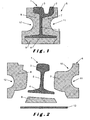
- the rail 1 shown in figure 1 is a rail including a groove 2, while the rail shown in FIG. figure 2 does not have such a throat.
- the invention is not limited to a particular type of rail and applies to both grooved rails and rails without grooves as well as to other types of rails, such as the three-rail pieces illustrated at the figure 6 .
- Each rail comprises a rail head 3 and a shoe 4 interconnected by an amount 5.
- the jacket 6 may either consist of a single piece or three pieces 7, 8 and 9.
- the jacket covers the rail vehicle rail parts that are not in contact with the wheels of the vehicle. The part in contact with the wheels of the vehicle must indeed remain free so as not to hinder the passage of the wheel.
- the jacket is preferably glued to the rail.
- the jacket is in one part, it is obtained by injection into a mold as will be described below.
- the jacket In order to give the jacket the required properties, the latter is made of rubber, preferably recycled rubber obtained by grinding and screening used tires.
- the jacket is formed from rubber granules having a particle size between 0.5 - 6 mm, in particular between 1 and 3 mm. This fineness of granules makes it possible to compact the material of which the jacket is formed and thus to reduce the formation of air pockets within the jacket.
- the rubber granules are bonded together by an elastomeric resin, in particular polyurethane. In order to allow a good bonding of the granules with the resin, it is important that the granules are clean and free of dust or other fats.
- the concentration of ferrous materials is less than 1% of the total mass. This reduces electrical current leakage to earth and thus electrically isolate the rail.
- the concentration of textile and / or plastic material of the rubber is also preferably less than 1% of the total mass. Indeed, these materials form a pollutant in the rubber of the jacket and could reduce the consistency between the granules.
- the density of the material forming the jacket is greater than 950 kg / m3, in particular equal to 1 150 kg / m3. Since these jackets are, with the rail that they coat posed in the road where road vehicles also circulate, it is important that these jackets resist road traffic. A density higher than 950 kg / m3 allows good resistance to this type of traffic.
- the jacket has a static Young's modulus greater than 5 MPa and a dynamic Young's modulus less than 20 MPa.
- the material of which the jacket is formed preferably also includes additives such as anti-UV substances, as well as fire-retardant substances. Indeed, the jackets being exposed to the light of day, it is better to add anti-UV substances in order to prevent that the light destroys in the long run the structure of the jacket. The presence of fire-retardant substances will preserve the jacket in case a burning vehicle should be on the rail.
- the jacket has several functions. It seals the rail in its support and isolates it electrically and acoustically.
- the rail is first placed in the mold. Then the rubber mixed with the binder and provided with the necessary additives is injected at high pressure into the mold. The high-society This pressure prevents the formation of bubbles between the different granules and thus makes it possible to obtain a compacted material with a high density.
- Jackets can have multiple shapes, depending on the specific needs of different applications.
- the figure 2 shows a jacket 6 for symmetrical rail with rim 10.
- the lower part 9 of the jacket holds the rail at the desired inclination.
- the upper surface of the jacket is dimensioned to allow the passage of the vehicle wheels without touching the coatings and this taking into account a multitude of accumulated wear of the rail and wheels.
- the inner profile of the jacket matches that of the rail against which it is applied.
- the external profile of the lateral flanks of the jacket which extend along the rail is itself determined by the desired distribution of the load exerted by the vehicle when it travels on the rail. Indeed, the composition of the floor on which the coated rail of its jacket is placed, the proximity of buildings, the fact that the rail is in clean site or not, etc ...., impose a particular distribution of the load exerted by the vehicle on the rail. The transfer of all the loads exerted on the rail must be done along the perimeter of the jacket to minimize the vibrations induced in the ground.
- the geometry of the external lateral flanks of the jacket makes it possible, by the choice of particular shapes, to distribute the charges differently.
- each lateral flank is configured such that to form a non-rectilinear profile that allows the determined distribution.
- the jacket has in its outer side flanks recesses 11 and 12 of substantially circular shape. These recesses extend to the height of the rail 5.
- This geometry allows a distribution of the bearings for the first fraction, that is to say that exerted on the head of the rail, located between 60 and 80%, in particular 70%.
- this geometry resumes between 40 and 20%, in particular 30% of the load. This then makes it possible to arrive at an overall stiffness of the rail-jacket complex of the order of 35 MN / m per meter of rail.
- FIG 9 which shows the relationship between the deflection (in mm) of the rail-jacket complex and the load (in kN) imposed on the complex
- the static stiffness of the rail-jacket complex follows a continuous curve, thus limiting the formation of induced shaking in the ground by the vehicle traveling on the rail.
- the figure 10 illustrates the dynamic stiffness of the complex. This dynamic stiffness follows a substantially linear path.
- the portion of the jacket located near the pad 4 is wider than that located at the height of the head 3 of the rail. This helps to form a better base of support on the ground.
- the thickness of the jacket is higher at the height of the upright 5 than that at the height of the head thus favorably contribute to distribute most of the load on the head of the rail.
- the jacket is also asymmetrical in thickness at the height of the head. The portion along the lug is thinner than the one on the opposite side to allow more flexibility to the volume between the rails.
- the jacket may also have asymmetrical recesses.
- This same figure 2 also illustrates that it is possible by giving an inclination to the portion 9 of the jacket located under the pad 4 to adjust the inclination of the rail. It is also possible to further reduce the sound insulation by placing a support plate 13 under the jacket.
- the figure 3 shows an embodiment of the jacket where the recesses 15 and 16 have a substantially U-shaped flared shape.
- This form allows a substantially equal distribution of charges between the head 3 and the pad 4 of the rail. This then makes it possible to arrive at an overall stiffness of the rail-jacket complex of the order of 80 MN / m per meter of rail. This solution is generally used in low density buildings.
- the configuration illustrated in figure 3 also shows an asymmetrical shape on both side flanks of the jacket.
- the figure 4 shows an embodiment of the jacket where the recess is formed to have a trapezoidal geometry.
- This geometry allows a distribution of the bearings for the first fraction located between 20 and 40%, in particular 30%.
- this geometry resumes between 60 and 80%, in particular 70% of the load. This then makes it possible to arrive at an overall stiffness of the rail-jacket complex of the order of 25 MN / m per meter of rail.
- this embodiment makes it possible to manufacture a jacket which has only two parts 7 and 8.
- a seal 19 may be cast along the head of the rail.
- the figure 5 shows an embodiment of the jacket where the geometry is formed by protuberances 20 and 21. This geometry allows an equal distribution of the load on the entire jacket.
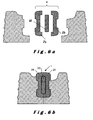
- the figure 6a shows an embodiment for a three-component rail 1, 22, 23 and 24. As shown in FIG. figure 6b it's the jacket that holds the rail components.
- the figure 8 shows a rail provided with its jacket as well as metal plates 32 and 33 against the coating hump. These plates make it possible to form an intermediate piece between the coating and the jacket and thus protect the jacket.
- the protuberances or recesses not only serve to allow a distribution of the charges, but also to form a plug for a concrete, bitumen or other aggregation of granules bound by means of a binder.
- the rail when the rail is embedded in its jacket, it can be placed at a distance of distance without using iron sleepers screwed to the rail.
- the placement of the rail-jacket complex is carried out using a laying gantry.
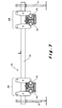
- the gantry 25 comprises a transverse arm 26 on which jaws 27 and 28 are mounted so as to establish a gap between the rails.
- the jaws are provided with engaging members 29 configured to match the profile applied in the outer flanks of the jacket. Thus these elements 29 can take hold on the jacket.
- the portal gantry comprises two side screws 30 and 31.
- the gantry installation maintains the rail-jacket assembly by jaws and fits into the side spaces left in the sides of the jacket.
- a suitable spacing device maintains the two rails to be laid at the proper spacing.
- the two side screws 30 and 31 bring the whole level to the right level.
- Another gantry system supports the rail by a steel plate passing under the iso-seal and connected to the gantry with two bolts.
- the assembly is mounted on a slider to allow the training of the track.
- the rail-jacket complex is inserted in a prefabricated beam and delivered to the site after drying.
- These elements have varying lengths depending on the needs of the site and can be up to 25 meters long.
- These beams are armed to support the passage of rolling stock (tram, ...) on supports every 3 meters.
- the beams having two lateral surfaces can receive prefabricated elements of coating.
- the visible part of the beam is designed to receive a modular type of cladding element (brick, concrete block, small material) or to be disbursed from the height necessary to put asphalt pavement or other.
- the reinforcement constituting the beam may be exceeded from the material constituting the beam, in order to be taken up in the concrete blocking.
- prefabricated elements are inserted between the beams and outside of them to fully materialize the entire track. These panels are blocked by injection of concrete under all the prefabricated elements once they are set. The space between the modules is closed by a suitable seal.
- Prefabricated coatings can contain any type of coating usually used in pavements.
- the two rails of the same track are included in a concrete slab in which are also included the end of site border and the platform heads.
- a sub foundation can be performed at the bottom of the chest. Once this is done, calibration slabs are laid and adjusted approximately.
- the crossroad slabs are then deposited on them and adjusted by interposition of shims of varying thickness.
- the intersection can be treated in two or three slabs in its width.
- the intersections can be treated in several slabs according to their lengths. Spaces between slabs are then left in order to perform the rail welds between the different modules. At this location, smaller slabs are added to the track slabs to ensure continuity of the pavement.
- the rail-jacket complex also makes it easy to remove the rail. Indeed, just cut the jacket on the height of the side flanks. The rail and the remaining parts glued to the rail are then removed, for example using a crane. A new rail provided with a jacket portion can then be placed in the opening obtained after removal of the cut parts.
Landscapes
- Engineering & Computer Science (AREA)
- Architecture (AREA)
- Civil Engineering (AREA)
- Structural Engineering (AREA)
- Railway Tracks (AREA)
- Machines For Laying And Maintaining Railways (AREA)
- Application Of Or Painting With Fluid Materials (AREA)
- Vehicle Interior And Exterior Ornaments, Soundproofing, And Insulation (AREA)
- Road Paving Structures (AREA)
- Train Traffic Observation, Control, And Security (AREA)
Description
- La présente invention concerne un procédé d'enrobage des parties d'un rail pour des véhicules ferroviaires qui ne sont pas en contact avec les roues du véhicule, lequel procédé comprend l'application d'une jaquette en caoutchouc sur lesdites parties et la fixation de cette jaquette au rail, ladite jaquette ayant des flancs latéraux extérieurs qui s'étendent le long du rail.
- Un tel procédé est connu de la demande de brevet
EP 0854234 . La jaquette est formée de blocs en caoutchouc qui sont appliqués tant contre les flancs latéraux du rail que sous le patin du rail. L'utilisation de ces jaquettes permet de réduire considérablement les vibrations induites dans le sol par le véhicule lors de son passage sur les rails. La réduction des vibrations permet à son tour de réduire la nuisance et les dégâts pour les riverains. - Un désavantage du procédé connu est que toutes les jaquettes ont la même configuration et n'exercent qu'une fonction d'absorption des vibrations. De plus, les jaquettes connues ne permettent pas par leur géométrie, qui en général épouse celle du rail, de jouer sur la répartition des charges appliquées par le véhicule lorsqu'il circule sur le rail enrobé de sa jaquette.
- L'invention a pour but de réaliser un procédé d'enrobage des parties d'un rail pour véhicule ferroviaire qui ne sont pas en contact avec les roues du véhicule, où il est possible d'adapter la répartition des charges appliquées au rail par le véhicule.
- A cette fin, un procédé suivant l'invention est caractérisé en ce que pour une charge prédéterminée exercée par ledit véhicule sur le rail, une répartition de cette charge entre une première fraction exercée sur la tête du rail et une deuxième fraction de cette charge exercée sur le patin du rail est déterminée, la géométrie de chaque flanc latéral étant configurée de telle façon à former un profil non-rectiligne permettant ladite répartition entre ladite première et deuxième fraction. La répartition des charges entre celles exercées sur la tête du rail et celles exercées sur le patin du rail permet de mieux gérer la charge exercée sur le rail et de contribuer ainsi non seulement à une réduction des vibrations induites par le véhicule dans le sol, mais également au confort des passagers utilisant le véhicule et à la durée de vie de la jaquette. Le fait de
configurer la géométrie de chaque flanc latéral en fonction de la répartition déterminée des charges permet de donner à la jaquette la flexibilité et la rigidité nécessaires pour permettre cette répartition. - Une première forme préférentielle d'un procédé suivant l'invention est caractérisée en ce que ladite géométrie est configurée en forme d'évidement. La forme d'évidement permet de diriger la charge vers le rail suivant la répartition déterminée.
- De préférence ledit évidement est formé sensiblement circulaire. La forme circulaire de l'évidement permet de repartir la majeure partie de la charge sur la tête du rail.
- Une deuxième forme préférentielle d'un procédé suivant l'invention est caractérisée en ce que ledit évidement est formé sensiblement en U évasé. Cette forme permet d'arriver à une raideur d'environ 80 MN/m par mètre de rail.
- Une troisième forme préférentielle d'un procédé suivant l'invention est caractérisée en ce que ledit évidement est formé de façon à posséder une géométrie trapézoïdale. Cette forme permet de réduire considérablement les vibrations induites dans le sol par les véhicules passant sur le rail.
- Une quatrième forme préférentielle d'un procédé suivant l'invention est caractérisée en ce que sous le patin dudit rail est placée une bande formée d'un caoutchouc plus souple que celui de la jaquette, ladite bande étant logée entre la face inférieure du patin et la jaquette. Cette bande en caoutchouc plus souple permet un transfert de l'ordre de 70 % sur le patin du rail pour arriver à une raideur de la jaquette de l'ordre de 15MN/m par mètre de rail.
- Une cinquième forme préférentielle d'un procédé suivant l'invention est caractérisée en ce que la jaquette est formée de granules de caoutchouc liés entre eux par une résine élastomère, en particulier du polyuréthane, les granules ayant une granulométrie située entre 0,5 - 6 mm, en particulier entre 1 et 3 mm. Ceci permet de produire une jaquette homogène.
- De préférence la concentration du matériau ferreux, textile et plastique dans les granules de caoutchouc est chaque fois inférieure à 1 %. Cette faible concentration en matériau ferreux permet de produire une jaquette ayant une mauvaise conductivité électrique, ce qui est favorable pour réduire les pertes de courant. La faible concentration en textile et plastique contribue à l'homogénéité de la jaquette.
- De préférence, la densité de la matière formant la jaquette est supérieure à 950 kg/m3, en particulier égale à 1150 kg/m3. Une telle densité permet la fabrication d'une jaquette résistante en particulier à la circulation routière.
- Une sixième forme préférentielle d'un procédé suivant l'invention est caractérisée en ce que le rail est posé dans un moule et en ce que les granules et la résine sont mélangés entre eux et injectés sous haute pression dans le moule. Cette injection à haute pression permet de produire une jaquette à haute densité de matière.
- L'invention concerne également un procédé de pose de deux rails afin de former une voie ferrée dans laquelle des rails enrobés par utilisation du procédé susdit sont utilisés. Un tel procédé est caractérisé en ce que les rails sont montés dans un portique de pose afin de les mettre à distance d'écartement, lesdits rails étant ensuite disposés à l'aide dudit portique sur une base préparée au préalable, et en ce qu'on coule ensuite au moins dans l'espace entre les deux rails une agrégation de granules liés au moyen d'un liant. Ceci permet une pose rapide et efficace des rails.
- Enfin l'invention concerne un procédé d'enlèvement d'un rail posé par application du procédé susdit. Un tel procédé est caractérisé en ce que la jaquette est découpée sur la hauteur des flancs latéraux avant enlèvement du rail et la partie restante appliquée au rail de la jaquette. Il suffit ainsi de découper la jaquette, d'enlever l'ensemble découpé et de reposer un nouveau rail enrobé de sa jaquette.
- L'invention sera maintenant décrite plus en détail à l'aide des dessins illustrant des exemples du procédé suivant l'invention. Dans les dessins :
- la
figure 1 montre une première forme de réalisation d'un rail enrobé par application du procédé suivant l'invention; - la
figure 2 montre une forme alternative de celle illustrée à lafigure 1 ; - la
figure 3 montre une deuxième forme de réalisation d'un rail enrobé par application du procédé suivant l'invention; - la
figure 4 montre une troisième forme de réalisation d'un rail enrobé par application du procédé suivant l'invention; - la
figure 5 montre un rail enrobé d'une jaquette permettant le renouvellement du rail sans démontage du revêtement; - la
figure 6 montre une forme de réalisation pour un rail à trois pièces; - la
figure 7 montre le procédé de pose de deux rails enrobés; - la
figure 8 montre une jaquette avec plat métallique de contre buttage du revêtement; - la
figure 9 montre la relation entre la déflection (en mm) du complexe rail-jaquette et la charge (en kN) imposée au complexe; - la
figure 10 illustre la raideur dynamique du complexe; et - la
figure 11 montre la déflection du bogie du véhicule. - Dans les dessins, une même référence a été attribuée à un même élément ou à un élément analogue.
- Le rail 1 illustré à la
figure 1 est un rail comprenant une gorge 2, alors que le rail illustré à lafigure 2 ne comporte pas une telle gorge. Bien entendu, l'invention n'est pas limitée à un type particulier de rail et s'applique tant à des rails avec gorge qu'à des rails sans gorge ainsi qu'à d'autres types de rails, comme le rail à trois pièces illustré à lafigure 6 . Chaque rail comporte une tête de rail 3 ainsi qu'un patin 4 reliés entre eux par un montant 5. - La jaquette 6 peut, soit être constituée d'une seule pièce ou de trois pièces 7, 8 et 9. La jaquette enrobe les parties du rail pour véhicule ferroviaire qui ne sont pas en contact avec les roues du véhicule. La partie en contact avec les roues du véhicule doit en effet rester libre afin de ne pas gêner le passage de la roue. Lorsque la jaquette est en plusieurs parties, elle est de préférence collée au rail. Par contre, lorsque la jaquette est en une seule partie elle est obtenue par injection dans un moule comme il sera décrit ci-dessous.
- Afin de donner les propriétés requises à la jaquette, cette dernière est fabriquée en caoutchouc, de préférence en caoutchouc recyclé obtenu par broyage et criblage de pneus usagés. La jaquette est formée à partir de granules de caoutchouc ayant une granulométrie située entre 0,5 - 6 mm en particulier entre 1 et 3 mm. Cette finesse de granules permet de compacter la matière dont est formée la jaquette et de réduire ainsi la formation de poches d'air au sein de la jaquette. Les granules de caoutchouc sont liés entre eux par une résine élastomère, en particulier du polyuréthane. Afin de permettre une bonne liaison des granules à l'aide de la résine, il est important que les granules soient propres et dépouillés de poussière ou d'autres matières grasses.
- Afin de réduire la conductivité électrique de la jaquette, la concentration en matériaux ferreux est inférieure à 1 % de la masse totale. Ceci permet de réduire des fuites de courant électrique vers la terre et d'ainsi isoler électriquement le rail. La concentration en matériau textile et/ou plastique du caoutchouc est également de préférence inférieure à 1 % de la masse totale. En effet, ces matières forment un polluant dans le caoutchouc de la jaquette et pourraient réduire la cohérence entre les granules.
- La densité de la matière formant la jaquette est supérieure à 950 kg/m3, en particulier égale à 1 150 kg/m3. Puisque ces jaquettes sont, avec le rail qu'elles enrobent posées dans la route où circulent également des véhicules routiers, il est important que ces jaquettes résistent au trafic routier. Une densité supérieure à 950 kg/m3 permet une bonne résistance à ce type de trafic.
- La jaquette possède un module de Young statique supérieur à 5MPa et un module de Young dynamique inférieur à 20MPa.
- La matière dont est formée la jaquette comporte de préférence également des additifs tels que des substances anti-UV, ainsi que des substances retardatrices de feu. En effet, les jaquettes étant exposées à la lumière du jour, il est préférable d'ajouter des substances anti-UV afin d'empêcher que la lumière détruise à la longue la structure de la jaquette. La présence des substances retardatrices de feu permettra de préserver la jaquette au cas où un véhicule en feu devrait se trouver sur le rail.
- La jaquette possède plusieurs fonctions. Elle scelle le rail dans son support et l'isole électriquement et acoustiquement. Lorsque la jaquette est fabriquée en une seule pièce par injection dans un moule reprenant la forme de la jaquette, le rail est d'abord posé dans le moule. Ensuite le caoutchouc mélangé au liant et pourvu des additifs nécessaires est injecté à haute pression dans le moule. La haute pression empêche la formation de bulles entre les différents granules et permet ainsi d'obtenir une matière compactée à haute densité.
- Les jaquettes peuvent avoir de multiples formes, suivant les besoins spécifiques des différentes applications. La
figure 2 montre une jaquette 6 pour rail symétrique avec ornière de mentonnet 10. La partie basse 9 de la jaquette maintient le rail à l'inclinaison voulue. La surface supérieure de la jaquette est dimensionnée pour permettre le passage des roues du véhicule sans toucher les revêtements et ceci en prenant en compte une multitude d'usures cumulées du rail et des roues. - Le profil intérieur de la jaquette épouse celui du rail contre lequel elle est appliquée. Le profil extérieur des flancs latéraux de la jaquette qui s'étendent le long du rail est quant à lui déterminé par la répartition voulue de la charge exercée par le véhicule lorsqu'il circule sur le rail. En effet, la composition du sol sur lequel le rail enrobé de sa jaquette est posé, la proximité d'immeubles, le fait que le rail se trouve en site propre ou non, etc...., imposent une répartition particulière de la charge exercée par le véhicule sur le rail. Le transfert de l'ensemble des charges exercées sur le rail doit se faire le long du périmètre de la jaquette afin de réduire au maximum les vibrations induites dans le sol. La géométrie des flancs latéraux externes de la jaquette permet par le choix de formes particulières de repartir différemment les charges.
- Pour arriver à cette répartition on détermine en fonction du sol et des autres paramètres susdits une répartition de la charge entre une première fraction exercée sur la tête 3 du rail et une deuxième fraction exercée sur le patin 4 du rail. Cette répartition entre la tête et le patin du rail permet de guider les vibrations soit dans un sens vertical ou dans un sens horizontal en fonction de l'environnement où le rail et sa jaquette seront posés. Après que la répartition de la charge a été déterminée, la géométrie de chaque flanc latéral est configurée de telle façon à former un profil non-rectiligne qui permet la répartition déterminée.
- Dans l'exemple de réalisation illustré à la
figure 1 , la jaquette possède dans ses flancs latéraux extérieurs des évidements 11 et 12 de forme sensiblement circulaire. Ces évidements s'étendent à hauteur du montant 5 du rail. Cette géométrie permet une répartition des portances pour la première fraction, c'est-à-dire celle exercée sur la tête du rail, située entre 60 et 80 %, en particulier 70 %. Pour la deuxième fraction, cette géométrie reprend entre 40 et 20 %, en particulier 30 % de la charge. Ceci permet alors d'arriver à une raideur globale du complexe rail-jaquette de l'ordre de 35MN/m par mètre de rail. Comme illustré à lafigure 9 , qui montre la relation entre la déflection (en mm) du complexe rail-jaquette et la charge (en kN) imposée au complexe, la raideur statique du complexe rail-jaquette suit une courbe continue, limitant ainsi la formation de secousses induites dans le sol par le véhicule circulant sur le rail. Lafigure 10 illustre la raideur dynamique du complexe. Cette raideur dynamique suit un parcours sensiblement linéaire. Ces propriétés du complexe rail-jaquette contribuent également au confort des passagers. En effet comme illustré à lafigure 11 , qui montre la déflection du bogie, ce dernier subit une ondulation sensiblement sinusoïdale. - Comme illustré à la
figure 1 , la partie de la jaquette située près du patin 4 est plus large que celle située à hauteur de la tête 3 du rail. Ceci permet de former une meilleure base de support sur le sol. De plus, l'épaisseur de la jaquette est plus élevée à hauteur du montant 5 que celle à hauteur de la tête permettant ainsi de favorablement contribuer à repartir la plus grande partie de la charge sur la tête du rail. La jaquette est également asymétrique en épaisseur à hauteur de la tête. La partie longeant le mentonnet est plus mince que celle située du côté opposé pour permettre davantage la flexibilité vers le volume situé entre les rails. - Comme illustré à la
figure 2 , la jaquette peut également avoir des évidements asymétriques. Cette mêmefigure 2 illustre également qu'il est possible en donnant une inclinaison à la partie 9 de la jaquette se trouvant sous le patin 4 de régler l'inclinaison du rail. Il est également possible de réduire davantage l'isolation acoustique en plaçant sous la jaquette une plaque d'appui 13. - La
figure 3 montre une forme de réalisation de la jaquette où les évidements 15 et 16 ont une forme sensiblement en U évasé. Cette forme permet une répartition des charges sensiblement égale entre la tête 3 et le patin 4 du rail. Ceci permet alors d'arriver à une raideur globale du complexe rail-jaquette de l'ordre de 80 MN/m par mètre de rail. Cette solution est en général utilisée dans des environnements à faible densité d'immeubles. La configuration illustrée à lafigure 3 montre également une forme asymétrique sur les deux flancs latéraux de la jaquette. - La
figure 4 montre une forme de réalisation de la jaquette où l'évidement est formé de façon à posséder une géométrie trapézoïdale. Cette géométrie permet une répartition des portances pour la première fraction située entre 20 et 40 %, en particulier 30 %. Pour la deuxième fraction cette géométrie reprend entre 60 et 80 %, en particulier 70% de la charge. Ceci permet alors d'arriver à une raideur globale du complexe rail-jaquette de l'ordre de 25MN/m par mètre de rail. - Comme illustré à la
figure 4 , cette forme de réalisation permet de fabriquer une jaquette qui ne comporte que deux parties 7 et 8. De plus, un joint d'étanchéité 19 peut être coulé le long de la tête du rail. - La
figure 5 montre une forme de réalisation de la jaquette où la géométrie est formée par des protubérances 20 et 21. Cette géométrie permet une répartition égale de la charge sur l'ensemble de la jaquette. - La
figure 6a montre une forme de réalisation pour un rail 1 à trois composants 22, 23 et 24. Comme illustré à lafigure 6b , c'est la jaquette qui maintient les composants du rail. - La
figure 8 montre un rail pourvu de sa jaquette ainsi que de plaques métalliques 32 et 33 de contre buttage de revêtement. Ces plaques permettent de former une pièce intermédiaire entre le revêtement et la jaquette et d'ainsi protéger la jaquette. - Il est également possible de placer sous le patin du rail une bande formée d'un caoutchouc plus souple que celui dont est fabriquée la jaquette. La bande est logée entre la face inférieure du patin et la jaquette et permet de réduire davantage les vibrations.
- Les protubérances ou évidements non seulement servent à permettre une répartition des charges, mais également à former une prise pour un béton, bitume ou autre agrégation de granules liés au moyen d'un liant. En effet, lorsque le rail est enrobé dans sa jaquette, il peut être mis à distance d'écartement sans faire appel à des traverses en fer vissées au rail. Le placement du complexe rail-jaquette est réalisé à l'aide d'un portique de pose. Comme illustré à la
figure 7 , le portique de pose 25 comporte un bras transversal 26 sur lequel sont montées des mâchoires 27 et 28 de telle façon à établir d'écart entre les rails. Les mâchoires sont pourvues d'éléments de prise 29 configurés de façon à correspondre au profil appliqué dans les flancs extérieurs de la jaquette. Ainsi ces éléments 29 peuvent prendre prise sur la jaquette. Enfin, le portique de pose comporte deux vis latérales 30 et 31. Le portique de pose maintient l'ensemble rail-jaquette par des mâchoires et s'insert dans les espaces latéraux laissés dans les flancs de la jaquette. Un dispositif d'écartement adapté maintient les deux rails à poser au bon écartement. Les deux vis latérales 30 et 31 amènent au bon niveau l'ensemble. - Un autre système de portique soutient le rail par un plat d'acier passant sous l'iso scelle et relié au portique de pose par deux boulons. L'ensemble est monté sur coulisseau pour permettre le dressage de la voie.
- Afin de rendre l'exécution du chantier plus rapide, le complexe rail-jaquette est inséré dans une poutre préfabriquée et livrée au chantier après séchage. Ces éléments ont des longueurs variables suivant les besoins du chantier et peuvent aller jusqu'à 25 mètre de long. Ces éléments poutres sont armés de façon à pouvoir supporter le passage du matériel roulant (tram, ...) sur appuis tous les 3 mètres. Les poutres possédant deux portées latérales peuvent recevoir des éléments préfabriqués de revêtement. La partie visible de la poutre est conçue pour recevoir un élément de revêtement de type modulaire (brique, pavé béton, petit matériel) ou pour être décaissé de la hauteur nécessaire pour mettre un revêtement en asphalte ou autre.
- L'armature constituant la poutre peut être dépassée de la matière constituant la poutre, afin d'être reprise dans les bétons de calage. Afin de réduire le temps de réalisation des chantiers, des éléments préfabriqués de revêtement sont insérés entre les poutres et à l'extérieur de celles-ci afin de matérialiser complètement l'ensemble de la voie. Ces panneaux sont bloqués par injection de béton sous l'ensemble des éléments préfabriqués une fois ceux-ci réglés. L'espace entre les modules est fermé par un joint adapté. Les revêtements préfabriqués peuvent contenir tout type de revêtement habituellement employé dans les chaussées.
- Afin de réaliser encore plus vite les chantiers, spécialement aux carrefours, ou pour donner accès à des riverains prioritaires, les deux rails d'une même voie sont inclus dans une dalle de béton dans laquelle sont aussi inclues la bordure de fin de site et les têtes de plate-forme. Lorsque le terrassement du coffre de la voie est réalisé, une sous fondation peut être exécutée au fond du coffre. Une fois celle-ci réalisée, des hourdis de calage sont posés et réglés approximativement.
- Les dalles de carrefour sont alors déposées sur ceux-ci et réglés par interposition de cales d'épaisseur variable. Le carrefour peut être traité en deux ou trois dalles dans sa largeur. Les carrefours peuvent être traités en plusieurs dalles suivant leurs longueurs. Des espaces entre dalles sont alors laissés afin de réaliser les soudures de rails entre les différents modules. A cet endroit, des dalles plus petites sont rapportées aux dalles de voie afin d'assurer la continuité du revêtement.
- Une fois les dalles bien positionnées, les soudures réalisées, les dalles intercalaires posées, un béton liquide est injecté sous l'ensemble des éléments constituants les voies et bloque définitivement ceux-ci. Si, de part et d'autre de ces modules de voie préfabriqués la pose de voie est différente, des zones de transition sont ajoutées pour assurer une transition dans les raideurs et aussi permettre le bourrage des traverses adjacentes dans le cas des voies ballastées.
- Le complexe rail-jaquette permet également d'enlever facilement le rail. En effet, il suffit de découper la jaquette sur la hauteur des flancs latéraux. Le rail et les parties restantes collées au rail sont ensuite enlevés, par exemple à l'aide d'une grue. Un nouveau rail pourvue d'une partie de jaquette peut alors être posé dans l'ouverture obtenue après enlèvement des parties découpées.
Claims (18)
- Procédé d'enrobage des parties d'un rail pour des véhicules ferroviaires qui ne sont pas en contact avec les roues du véhicule, lequel procédé comprend l'application d'une jaquette en caoutchouc sur lesdites parties et la fixation de cette jaquette au rail, ladite jaquette ayant des flancs latéraux extérieurs qui s'étendent le long du rail, caractérise en ce que pour une charge prédéterminée exercée par ledit véhicule sur le rail, une répartition de cette charge entre une première fraction exercée sur la tête du rail et une deuxième fraction de cette charge exercée sur le patin du rail est déterminée, la géométrie de chaque flanc latéral étant configurée de telle façon à former un profil non-rectiligne permettant ladite répartition entre ladite première et deuxième fraction.
- Procédé suivant la revendication 1, caractérisé en ce que ladite géométrie est configurée en forme d'évidement.
- Procédé suivant la revendication 2, caractérisé en ce que ledit évidement est formé sensiblement circulaire.
- Procédé suivant la revendication 2, caractérisé en ce que ledit évidement est formé sensiblement en U évasé.
- Procédé suivant la revendication 2, caractérisé en ce que ledit évidement est formé de façon à posséder une géométrie trapézoïdale.
- Procédé suivant la revendication 1, caractérisé en ce que ladite géométrie est configurée en forme de protubérance comprenant au moins une arête.
- Procédé suivant la revendication 1, 2 ou 3, caractérisé en ce que ladite première fraction est située entre 60 et 80 %, en particulier 70 %, de la charge et la deuxième fraction est située entre 40 et 20 %, en particulier 30 % de la charge.
- Procédé suivant la revendication 1, 2 ou 5, caractérisé en ce que ladite première fraction est située entre 20 et 40 %, en particulier 30 %, et ladite deuxième fraction est située entre 60 et 80 %; en particulier 70 % de la charge.
- Procédé suivant l'une des revendications 1 à 8, caractérisé en ce que sous le patin dudit rail est placée une bande formée d'un caoutchouc plus souple que celui de la jaquette, ladite bande étant logée entre la face inférieure du patin et la jaquette.
- Procédé suivant l'une des revendications 1 à 9, caractérisé en ce que la jaquette est formée de granules de caoutchouc liés entre eux par une résine élastomère, en particulier du polyuréthane, les granules ayant une granulométrie située entre 0,5 - 6 mm, en particulier entre 1 et 3 mm.
- Procédé suivant la revendication 10, caractérisé en ce que la concentration du matériau ferreux, textile et plastique dans les granules de caoutchouc est chaque fois inférieure à 1 %.
- Procédé suivant la revendication 10 ou 11, caractérisé en ce que la densité de la matière formant la jaquette est supérieure à 950 kg/m3, en particulier égale à 1150 kg/m3.
- Procédé suivant l'une des revendications 10 à 12, caractérisé en ce que la jaquette possède un module de Young statique supérieur à 5 MPa et un module de Young dynamique inférieur à 20 MPa.
- Procédé suivant l'une des revendications 10 à 13, caractérisé en ce que pour former la jaquette des substances anti-UV, des substances retardatrices de feu sont ajoutées avant de lier les granules entre eux..
- Procédé suivant l'une des revendications 10 à 14, caractérisé en ce que le rail est posé dans un moule et en ce que les granules et la résine sont mélangés entre eux et injectés sous haute pression dans le moule.
- Procédé de pose de deux rails afin de former une voie ferrée dans laquelle des rails enrobés par utilisation du procédé suivant l'une des revendications 1 à 15 sont utilisés, caractérisé en ce que les rails sont montés dans un portique de pose afin de les mettre à distance d'écartement, lesdits rails étant ensuite disposés à l'aide dudit portique sur une base préparée au préalable, et en ce qu'on coule au moins dans l'espace entre les deux rails une agrégation de granules liés au moyen d'un liant.
- Procédé suivant la revendication 16, caractérisé en ce qu'un revêtement routier est posé sur ladite agrégation après séchage de cette dernière.
- Procédé d'enlèvement d'un rail posé par application du procédé suivant la revendication 16, caractérisé en ce que la jaquette est découpée sur la hauteur des flancs latéraux avant enlèvement du rail et la partie restante appliquée au rail de la jaquette.
Priority Applications (1)
| Application Number | Priority Date | Filing Date | Title |
|---|---|---|---|
| PL05791921T PL1807569T3 (pl) | 2004-09-21 | 2005-09-21 | Sposób powlekania szyn dla pojazdów szynowych |
Applications Claiming Priority (2)
| Application Number | Priority Date | Filing Date | Title |
|---|---|---|---|
| BE200400461 | 2004-09-21 | ||
| PCT/EP2005/054737 WO2006032684A1 (fr) | 2004-09-21 | 2005-09-21 | Procédé d'enrobage d'un rail pour véhicule ferroviaire. |
Publications (2)
| Publication Number | Publication Date |
|---|---|
| EP1807569A1 EP1807569A1 (fr) | 2007-07-18 |
| EP1807569B1 true EP1807569B1 (fr) | 2008-07-30 |
Family
ID=35695147
Family Applications (1)
| Application Number | Title | Priority Date | Filing Date |
|---|---|---|---|
| EP05791921A Revoked EP1807569B1 (fr) | 2004-09-21 | 2005-09-21 | Procédé d'enrobage d'un rail pour véhicule ferroviaire. |
Country Status (17)
| Country | Link |
|---|---|
| US (1) | US8602318B2 (fr) |
| EP (1) | EP1807569B1 (fr) |
| KR (1) | KR20070053814A (fr) |
| CN (1) | CN101052766A (fr) |
| AT (1) | ATE403034T1 (fr) |
| BR (1) | BRPI0515548A (fr) |
| CA (1) | CA2581089A1 (fr) |
| DE (1) | DE602005008631D1 (fr) |
| DK (1) | DK1807569T3 (fr) |
| ES (1) | ES2314714T3 (fr) |
| MA (1) | MA29710B1 (fr) |
| NO (1) | NO20071681L (fr) |
| PL (1) | PL1807569T3 (fr) |
| PT (1) | PT1807569E (fr) |
| TN (1) | TNSN07101A1 (fr) |
| WO (1) | WO2006032684A1 (fr) |
| ZA (1) | ZA200703165B (fr) |
Cited By (1)
| Publication number | Priority date | Publication date | Assignee | Title |
|---|---|---|---|---|
| DE102017127585A1 (de) | 2017-11-22 | 2019-05-23 | Het Elastomertechnik Gmbh | Brandhemmendes Schienenkammerfüllelement und Elastomerformteil |
Families Citing this family (20)
| Publication number | Priority date | Publication date | Assignee | Title |
|---|---|---|---|---|
| EP1895054A1 (fr) | 2006-08-31 | 2008-03-05 | Feronia S.A. | Dispositif antibruit d'un rail pour des véhicules ferroviaires |
| EP1988213A1 (fr) * | 2007-05-02 | 2008-11-05 | edilon)(sedra B.V. | Élément support de rail préfabriqué |
| ES2358495B1 (es) * | 2008-06-04 | 2012-03-26 | Acciona Infraestructuras, S.A | Material amortiguador de carril ferroviario, taco prefabricado de soporte de carril ferroviario que incorpora dicho material, carril encamisado en dicho material, y procedimiento de elaboración de dicho taco y dicho carril. |
| BE1019173A5 (nl) | 2010-02-03 | 2012-04-03 | Cdm N V | Trillingsdemper met een elastische mantel voor continu ondersteunde spoorstaven en werkwijze voor het bevestigen van deze trillingdemper. |
| BE1019172A5 (nl) | 2010-02-03 | 2012-04-03 | Cdm N V | Elektrische isolatie voor een trillingsdemper met een elastische m antel voor continu ondersteunde spoorstaven. |
| BE1019171A3 (nl) * | 2010-02-03 | 2012-04-03 | Cdm N V | Werkwijze voor het vervaardigen van een spoorwegbedding met een ingebedde continu ondersteunde spoortaaf. |
| BE1019353A3 (nl) * | 2010-05-28 | 2012-06-05 | Cdm N V | Trillingsdemper voor continu ondersteunde spoorstaven met een elastische mantel met een voorgevormd deel voorzien van een geintegreerde strip. |
| EP2420620A1 (fr) * | 2010-08-16 | 2012-02-22 | Acciona Infraestructuras, S.A. | Matériau isolant pour rails de chemin de fer |
| CN102071604B (zh) * | 2011-01-21 | 2012-11-28 | 朱颖 | 一种铁路钢轨用的减振降噪护套 |
| KR101128448B1 (ko) * | 2011-02-09 | 2012-03-27 | 김용택 | 프리캐스트 레일 장치의 시공방법 |
| CN102229488B (zh) * | 2011-05-16 | 2012-10-03 | 云南省建筑科学研究院 | 一种建筑模板支撑龙骨仿木填充浆料配方及加工方法 |
| EP2845951A1 (fr) | 2013-09-04 | 2015-03-11 | Prefarails Holding | Jaquette pour rail destiné aux véhicules ferroviaires |
| ES2570809B1 (es) * | 2014-11-19 | 2017-02-28 | Gestión Medioambiental De Neumáticos S.L. | Soporte amortiguador de vibraciones para vías férreas |
| CN105040535A (zh) * | 2015-08-28 | 2015-11-11 | 江阴海达橡塑股份有限公司 | 一种槽型轨轮缘槽防护胶条 |
| CN109280235A (zh) * | 2018-08-16 | 2019-01-29 | 四川川鼎轨道技术有限公司 | 一种钢轨轨腰柔性橡胶包覆件及其制备方法 |
| CN210886775U (zh) * | 2019-05-24 | 2020-06-30 | 青岛科而泰环境控制技术有限公司 | 组合式钢轨降噪吸声装置 |
| DE102020121136A1 (de) * | 2020-08-11 | 2022-02-17 | Sealable Solutions Gmbh | Elastomerprofil als Aufheizschutz für Schienen |
| CN115491934A (zh) * | 2022-09-26 | 2022-12-20 | 中铁二院工程集团有限责任公司 | 一种车辆通过小半径曲线地段的减震降噪护轨方法及装置 |
| FR3149027B1 (fr) * | 2023-05-26 | 2025-06-06 | Le Louer Sebastien | Structure de plateforme pour tramway |
| KR102700464B1 (ko) | 2023-11-23 | 2024-08-29 | 한국석유공업 주식회사 | 철도 건널목용 레일홈채움재 및 그 설치방법 |
Family Cites Families (6)
| Publication number | Priority date | Publication date | Assignee | Title |
|---|---|---|---|---|
| US1771078A (en) * | 1926-01-06 | 1930-07-22 | Carey Philip Mfg Co | Rail-expansion sound deadener |
| US5134863A (en) * | 1991-05-10 | 1992-08-04 | Mayer Industries, Inc. | Circular sliver knitting machine having increased carding capacity |
| GB9622924D0 (en) * | 1996-11-04 | 1997-01-08 | Alh Syst Ltd | Polymer embedment of rails |
| BE1010355A6 (fr) | 1997-01-16 | 1998-06-02 | Stephane Dirven | Dispositif anti-bruit. |
| DE19709111C2 (de) | 1997-03-06 | 2003-01-02 | Sedra Asphalt Technik Biebrich | Schienenkammerfüllelement zum maschinellen Einbau an Schienen sowie Einbauverfahren und -vorrichtung |
| BE1014315A3 (fr) * | 2001-07-25 | 2003-08-05 | Keyeux Jean Claude | Materiau enrobe a base de particules de caoutchouc vulcanise usage et son procede de fabrication. |
-
2005
- 2005-09-21 CA CA002581089A patent/CA2581089A1/fr not_active Abandoned
- 2005-09-21 EP EP05791921A patent/EP1807569B1/fr not_active Revoked
- 2005-09-21 BR BRPI0515548-7A patent/BRPI0515548A/pt not_active Application Discontinuation
- 2005-09-21 KR KR1020077009020A patent/KR20070053814A/ko not_active Withdrawn
- 2005-09-21 DK DK05791921T patent/DK1807569T3/da active
- 2005-09-21 PT PT05791921T patent/PT1807569E/pt unknown
- 2005-09-21 US US11/575,609 patent/US8602318B2/en not_active Expired - Fee Related
- 2005-09-21 DE DE602005008631T patent/DE602005008631D1/de not_active Expired - Lifetime
- 2005-09-21 AT AT05791921T patent/ATE403034T1/de active
- 2005-09-21 CN CNA2005800317241A patent/CN101052766A/zh active Pending
- 2005-09-21 ZA ZA200703165A patent/ZA200703165B/xx unknown
- 2005-09-21 WO PCT/EP2005/054737 patent/WO2006032684A1/fr not_active Ceased
- 2005-09-21 PL PL05791921T patent/PL1807569T3/pl unknown
- 2005-09-21 ES ES05791921T patent/ES2314714T3/es not_active Expired - Lifetime
-
2007
- 2007-03-22 TN TNP2007000101A patent/TNSN07101A1/fr unknown
- 2007-03-30 NO NO20071681A patent/NO20071681L/no not_active Application Discontinuation
- 2007-04-18 MA MA29833A patent/MA29710B1/fr unknown
Cited By (1)
| Publication number | Priority date | Publication date | Assignee | Title |
|---|---|---|---|---|
| DE102017127585A1 (de) | 2017-11-22 | 2019-05-23 | Het Elastomertechnik Gmbh | Brandhemmendes Schienenkammerfüllelement und Elastomerformteil |
Also Published As
| Publication number | Publication date |
|---|---|
| ES2314714T3 (es) | 2009-03-16 |
| DE602005008631D1 (de) | 2008-09-11 |
| ZA200703165B (en) | 2008-09-25 |
| PT1807569E (pt) | 2008-11-10 |
| US20090184439A1 (en) | 2009-07-23 |
| CN101052766A (zh) | 2007-10-10 |
| BRPI0515548A (pt) | 2008-07-29 |
| TNSN07101A1 (fr) | 2008-06-02 |
| US8602318B2 (en) | 2013-12-10 |
| WO2006032684A1 (fr) | 2006-03-30 |
| PL1807569T3 (pl) | 2009-06-30 |
| DK1807569T3 (da) | 2008-12-01 |
| CA2581089A1 (fr) | 2006-03-30 |
| EP1807569A1 (fr) | 2007-07-18 |
| NO20071681L (no) | 2007-06-20 |
| ATE403034T1 (de) | 2008-08-15 |
| KR20070053814A (ko) | 2007-05-25 |
| MA29710B1 (fr) | 2008-09-01 |
Similar Documents
| Publication | Publication Date | Title |
|---|---|---|
| EP1807569A1 (fr) | Procédé d'enrobage d'un rail pour véhicule ferroviaire. | |
| EP2191070B1 (fr) | Module prefabrique de voie pour vehicule de transport urbain autoguide sur pneumatiques | |
| EP0939164B1 (fr) | Procédé de construction d'une voie de chemin de fer | |
| EP2666907B1 (fr) | Voie de chemin de fer avec traverses sur dalle en béton continu et procédé de fabrication | |
| CS265399B1 (en) | Dilatation bridge closing device and method for producing thereof | |
| EP3263766B1 (fr) | Dalle pour un véhicule ferroviaire et/ou un véhicule sur pneus guidés | |
| CA2779340C (fr) | Plate-forme modulaire demontable pour dechetterie | |
| EP3067464B1 (fr) | Voie ferrée sur longrines longitudinales, procédé de réalisation | |
| EP1251204B1 (fr) | Système d'isolation vibratoire pour voies ferrées | |
| FR3019565A1 (fr) | Procede de realisation d'un carrefour de tramway | |
| BE1020879A4 (fr) | Coeur a pointe mobile pour rails a ornieres. | |
| FR2881150A1 (fr) | Structure de chaussee pour tramway sur pneus, et son procede de construction | |
| FR3025813A1 (fr) | Selle de support de rail de voie ferree | |
| RU2297488C1 (ru) | Железнодорожный переезд и способ изготовления резиножелезобетонных плит для него | |
| KR20140062757A (ko) | 도로 보수용 패널을 이용한 도로 보수 방법 | |
| EP0910702A1 (fr) | Procede d'assemblage de dalles pour constituer un revetement de sol et dalles pour la mise en oeuvre du procede | |
| KR101126695B1 (ko) | 저지지력지반도로 | |
| FR2982622A1 (fr) | Dalle en beton de support d'au moins deux files de rails d'une voie ferree et voie ferree equipee d'au moins une telle dalle | |
| RU105305U1 (ru) | Вкладыш для дорожного покрытия в трамвайных путях и дорожное покрытие в трамвайных путях, выполненное с использованием указанного вкладыша | |
| FR2872829A1 (fr) | Procede de pose de voie ferree encastree, moyens pour sa mise en oeuvre et voie ferree obtenue | |
| JP3720003B2 (ja) | 道路橋の埋設型ジョイント用の埋設継手及び道路橋の埋設型ジョイント | |
| FR2869628A1 (fr) | Procede de fabrication et de mise en place d'un joint pour rail, et notamment pour rail de tramway | |
| RU107796U1 (ru) | Дорожное покрытие в трамвайных путях с деревянным вкладышем | |
| BE1025482B1 (fr) | Assemblage d'elements de construction pour un passage a niveau | |
| FR3039173A1 (fr) | Pont pour le passage de troupeaux et procede de montage d’un tel pont |
Legal Events
| Date | Code | Title | Description |
|---|---|---|---|
| PUAI | Public reference made under article 153(3) epc to a published international application that has entered the european phase |
Free format text: ORIGINAL CODE: 0009012 |
|
| 17P | Request for examination filed |
Effective date: 20070420 |
|
| AK | Designated contracting states |
Kind code of ref document: A1 Designated state(s): AT BE BG CH CY CZ DE DK EE ES FI FR GB GR HU IE IS IT LI LT LU LV MC NL PL PT RO SE SI SK TR |
|
| DAX | Request for extension of the european patent (deleted) | ||
| GRAP | Despatch of communication of intention to grant a patent |
Free format text: ORIGINAL CODE: EPIDOSNIGR1 |
|
| GRAS | Grant fee paid |
Free format text: ORIGINAL CODE: EPIDOSNIGR3 |
|
| GRAA | (expected) grant |
Free format text: ORIGINAL CODE: 0009210 |
|
| REG | Reference to a national code |
Ref country code: HK Ref legal event code: DE Ref document number: 1110365 Country of ref document: HK |
|
| AK | Designated contracting states |
Kind code of ref document: B1 Designated state(s): AT BE BG CH CY CZ DE DK EE ES FI FR GB GR HU IE IS IT LI LT LU LV MC NL PL PT RO SE SI SK TR |
|
| REG | Reference to a national code |
Ref country code: GB Ref legal event code: FG4D Free format text: NOT ENGLISH |
|
| REG | Reference to a national code |
Ref country code: CH Ref legal event code: EP |
|
| REF | Corresponds to: |
Ref document number: 602005008631 Country of ref document: DE Date of ref document: 20080911 Kind code of ref document: P |
|
| REG | Reference to a national code |
Ref country code: IE Ref legal event code: FG4D Free format text: LANGUAGE OF EP DOCUMENT: FRENCH |
|
| REG | Reference to a national code |
Ref country code: PT Ref legal event code: SC4A Free format text: AVAILABILITY OF NATIONAL TRANSLATION Effective date: 20081029 |
|
| REG | Reference to a national code |
Ref country code: GR Ref legal event code: EP Ref document number: 20080402926 Country of ref document: GR |
|
| REG | Reference to a national code |
Ref country code: DK Ref legal event code: T3 |
|
| PG25 | Lapsed in a contracting state [announced via postgrant information from national office to epo] |
Ref country code: IS Free format text: LAPSE BECAUSE OF FAILURE TO SUBMIT A TRANSLATION OF THE DESCRIPTION OR TO PAY THE FEE WITHIN THE PRESCRIBED TIME-LIMIT Effective date: 20081130 Ref country code: LT Free format text: LAPSE BECAUSE OF FAILURE TO SUBMIT A TRANSLATION OF THE DESCRIPTION OR TO PAY THE FEE WITHIN THE PRESCRIBED TIME-LIMIT Effective date: 20080730 |
|
| PG25 | Lapsed in a contracting state [announced via postgrant information from national office to epo] |
Ref country code: SI Free format text: LAPSE BECAUSE OF FAILURE TO SUBMIT A TRANSLATION OF THE DESCRIPTION OR TO PAY THE FEE WITHIN THE PRESCRIBED TIME-LIMIT Effective date: 20080730 Ref country code: LV Free format text: LAPSE BECAUSE OF FAILURE TO SUBMIT A TRANSLATION OF THE DESCRIPTION OR TO PAY THE FEE WITHIN THE PRESCRIBED TIME-LIMIT Effective date: 20080730 Ref country code: BG Free format text: LAPSE BECAUSE OF FAILURE TO SUBMIT A TRANSLATION OF THE DESCRIPTION OR TO PAY THE FEE WITHIN THE PRESCRIBED TIME-LIMIT Effective date: 20081030 Ref country code: FI Free format text: LAPSE BECAUSE OF FAILURE TO SUBMIT A TRANSLATION OF THE DESCRIPTION OR TO PAY THE FEE WITHIN THE PRESCRIBED TIME-LIMIT Effective date: 20080730 |
|
| REG | Reference to a national code |
Ref country code: ES Ref legal event code: FG2A Ref document number: 2314714 Country of ref document: ES Kind code of ref document: T3 |
|
| PG25 | Lapsed in a contracting state [announced via postgrant information from national office to epo] |
Ref country code: MC Free format text: LAPSE BECAUSE OF NON-PAYMENT OF DUE FEES Effective date: 20080930 Ref country code: EE Free format text: LAPSE BECAUSE OF FAILURE TO SUBMIT A TRANSLATION OF THE DESCRIPTION OR TO PAY THE FEE WITHIN THE PRESCRIBED TIME-LIMIT Effective date: 20080730 |
|
| PLBI | Opposition filed |
Free format text: ORIGINAL CODE: 0009260 |
|
| PG25 | Lapsed in a contracting state [announced via postgrant information from national office to epo] |
Ref country code: CZ Free format text: LAPSE BECAUSE OF FAILURE TO SUBMIT A TRANSLATION OF THE DESCRIPTION OR TO PAY THE FEE WITHIN THE PRESCRIBED TIME-LIMIT Effective date: 20080730 Ref country code: SK Free format text: LAPSE BECAUSE OF FAILURE TO SUBMIT A TRANSLATION OF THE DESCRIPTION OR TO PAY THE FEE WITHIN THE PRESCRIBED TIME-LIMIT Effective date: 20080730 Ref country code: RO Free format text: LAPSE BECAUSE OF FAILURE TO SUBMIT A TRANSLATION OF THE DESCRIPTION OR TO PAY THE FEE WITHIN THE PRESCRIBED TIME-LIMIT Effective date: 20080730 |
|
| PLAX | Notice of opposition and request to file observation + time limit sent |
Free format text: ORIGINAL CODE: EPIDOSNOBS2 |
|
| 26 | Opposition filed |
Opponent name: EDILON)(SEDRA B.V. Effective date: 20090429 |
|
| REG | Reference to a national code |
Ref country code: HK Ref legal event code: WD Ref document number: 1110365 Country of ref document: HK |
|
| REG | Reference to a national code |
Ref country code: HU Ref legal event code: AG4A Ref document number: E005104 Country of ref document: HU |
|
| REG | Reference to a national code |
Ref country code: PL Ref legal event code: T3 |
|
| REG | Reference to a national code |
Ref country code: FR Ref legal event code: ST Effective date: 20090529 |
|
| NLR1 | Nl: opposition has been filed with the epo |
Opponent name: EDILON) (SEDRA B.V. |
|
| REG | Reference to a national code |
Ref country code: FR Ref legal event code: RN |
|
| PLAF | Information modified related to communication of a notice of opposition and request to file observations + time limit |
Free format text: ORIGINAL CODE: EPIDOSCOBS2 |
|
| PG25 | Lapsed in a contracting state [announced via postgrant information from national office to epo] |
Ref country code: FR Free format text: LAPSE BECAUSE OF NON-PAYMENT OF DUE FEES Effective date: 20080930 |
|
| REG | Reference to a national code |
Ref country code: FR Ref legal event code: FC |
|
| PLAF | Information modified related to communication of a notice of opposition and request to file observations + time limit |
Free format text: ORIGINAL CODE: EPIDOSCOBS2 |
|
| PLBB | Reply of patent proprietor to notice(s) of opposition received |
Free format text: ORIGINAL CODE: EPIDOSNOBS3 |
|
| PG25 | Lapsed in a contracting state [announced via postgrant information from national office to epo] |
Ref country code: SE Free format text: LAPSE BECAUSE OF FAILURE TO SUBMIT A TRANSLATION OF THE DESCRIPTION OR TO PAY THE FEE WITHIN THE PRESCRIBED TIME-LIMIT Effective date: 20081030 |
|
| PGRI | Patent reinstated in contracting state [announced from national office to epo] |
Ref country code: FR Effective date: 20100127 |
|
| PG25 | Lapsed in a contracting state [announced via postgrant information from national office to epo] |
Ref country code: LU Free format text: LAPSE BECAUSE OF NON-PAYMENT OF DUE FEES Effective date: 20080921 Ref country code: CY Free format text: LAPSE BECAUSE OF FAILURE TO SUBMIT A TRANSLATION OF THE DESCRIPTION OR TO PAY THE FEE WITHIN THE PRESCRIBED TIME-LIMIT Effective date: 20080730 |
|
| PLAB | Opposition data, opponent's data or that of the opponent's representative modified |
Free format text: ORIGINAL CODE: 0009299OPPO |
|
| PLAY | Examination report in opposition despatched + time limit |
Free format text: ORIGINAL CODE: EPIDOSNORE2 |
|
| PLAH | Information related to despatch of examination report in opposition + time limit modified |
Free format text: ORIGINAL CODE: EPIDOSCORE2 |
|
| PLBC | Reply to examination report in opposition received |
Free format text: ORIGINAL CODE: EPIDOSNORE3 |
|
| PGFP | Annual fee paid to national office [announced via postgrant information from national office to epo] |
Ref country code: DE Payment date: 20130919 Year of fee payment: 9 Ref country code: NL Payment date: 20130820 Year of fee payment: 9 Ref country code: CH Payment date: 20130919 Year of fee payment: 9 Ref country code: HU Payment date: 20130918 Year of fee payment: 9 Ref country code: DK Payment date: 20130918 Year of fee payment: 9 Ref country code: ES Payment date: 20130918 Year of fee payment: 9 Ref country code: IE Payment date: 20130927 Year of fee payment: 9 Ref country code: PT Payment date: 20130321 Year of fee payment: 9 Ref country code: AT Payment date: 20130911 Year of fee payment: 9 Ref country code: GR Payment date: 20130918 Year of fee payment: 9 |
|
| PGFP | Annual fee paid to national office [announced via postgrant information from national office to epo] |
Ref country code: FR Payment date: 20130821 Year of fee payment: 9 Ref country code: PL Payment date: 20130823 Year of fee payment: 9 Ref country code: TR Payment date: 20130823 Year of fee payment: 9 Ref country code: GB Payment date: 20130919 Year of fee payment: 9 |
|
| REG | Reference to a national code |
Ref country code: DE Ref legal event code: R064 Ref document number: 602005008631 Country of ref document: DE Ref country code: DE Ref legal event code: R103 Ref document number: 602005008631 Country of ref document: DE |
|
| PGFP | Annual fee paid to national office [announced via postgrant information from national office to epo] |
Ref country code: IT Payment date: 20130924 Year of fee payment: 9 |
|
| RDAF | Communication despatched that patent is revoked |
Free format text: ORIGINAL CODE: EPIDOSNREV1 |
|
| PGFP | Annual fee paid to national office [announced via postgrant information from national office to epo] |
Ref country code: BE Payment date: 20130911 Year of fee payment: 9 |
|
| RDAG | Patent revoked |
Free format text: ORIGINAL CODE: 0009271 |
|
| STAA | Information on the status of an ep patent application or granted ep patent |
Free format text: STATUS: PATENT REVOKED |
|
| REG | Reference to a national code |
Ref country code: CH Ref legal event code: PLX |
|
| 27W | Patent revoked |
Effective date: 20131211 |
|
| GBPR | Gb: patent revoked under art. 102 of the ep convention designating the uk as contracting state |
Effective date: 20131211 |
|
| REG | Reference to a national code |
Ref country code: PT Ref legal event code: MP4A Effective date: 20140528 |
|
| REG | Reference to a national code |
Ref country code: DE Ref legal event code: R107 Ref document number: 602005008631 Country of ref document: DE Effective date: 20140710 |
|
| PG25 | Lapsed in a contracting state [announced via postgrant information from national office to epo] |
Ref country code: CH Free format text: LAPSE BECAUSE OF THE APPLICANT RENOUNCES Effective date: 20080730 Ref country code: LI Free format text: LAPSE BECAUSE OF THE APPLICANT RENOUNCES Effective date: 20080730 |
|
| REG | Reference to a national code |
Ref country code: AT Ref legal event code: MA03 Ref document number: 403034 Country of ref document: AT Kind code of ref document: T Effective date: 20131211 |
|
| REG | Reference to a national code |
Ref country code: GR Ref legal event code: ML Ref document number: 20080402926 Country of ref document: GR Effective date: 20150403 |