EP1806471B1 - Sonnenschutzanlage mit Bewegungsschiene - Google Patents
Sonnenschutzanlage mit Bewegungsschiene Download PDFInfo
- Publication number
- EP1806471B1 EP1806471B1 EP20070000235 EP07000235A EP1806471B1 EP 1806471 B1 EP1806471 B1 EP 1806471B1 EP 20070000235 EP20070000235 EP 20070000235 EP 07000235 A EP07000235 A EP 07000235A EP 1806471 B1 EP1806471 B1 EP 1806471B1
- Authority
- EP
- European Patent Office
- Prior art keywords
- movable rail
- end caps
- rail
- elements
- protection system
- Prior art date
- Legal status (The legal status is an assumption and is not a legal conclusion. Google has not performed a legal analysis and makes no representation as to the accuracy of the status listed.)
- Not-in-force
Links
- 230000000475 sunscreen effect Effects 0.000 title 1
- 239000000516 sunscreening agent Substances 0.000 title 1
- 230000037072 sun protection Effects 0.000 claims description 11
- 230000015572 biosynthetic process Effects 0.000 description 2
- 238000006073 displacement reaction Methods 0.000 description 2
- 238000009434 installation Methods 0.000 description 2
- 239000011324 bead Substances 0.000 description 1
- 239000011521 glass Substances 0.000 description 1
- 238000003780 insertion Methods 0.000 description 1
- 230000037431 insertion Effects 0.000 description 1
- 230000003993 interaction Effects 0.000 description 1
- 230000009191 jumping Effects 0.000 description 1
- 230000002028 premature Effects 0.000 description 1
Images

Classifications
-
- E—FIXED CONSTRUCTIONS
- E06—DOORS, WINDOWS, SHUTTERS, OR ROLLER BLINDS IN GENERAL; LADDERS
- E06B—FIXED OR MOVABLE CLOSURES FOR OPENINGS IN BUILDINGS, VEHICLES, FENCES OR LIKE ENCLOSURES IN GENERAL, e.g. DOORS, WINDOWS, BLINDS, GATES
- E06B9/00—Screening or protective devices for wall or similar openings, with or without operating or securing mechanisms; Closures of similar construction
- E06B9/24—Screens or other constructions affording protection against light, especially against sunshine; Similar screens for privacy or appearance; Slat blinds
- E06B9/26—Lamellar or like blinds, e.g. venetian blinds
- E06B9/38—Other details
- E06B9/388—Details of bottom or upper slats or their attachment
-
- E—FIXED CONSTRUCTIONS
- E06—DOORS, WINDOWS, SHUTTERS, OR ROLLER BLINDS IN GENERAL; LADDERS
- E06B—FIXED OR MOVABLE CLOSURES FOR OPENINGS IN BUILDINGS, VEHICLES, FENCES OR LIKE ENCLOSURES IN GENERAL, e.g. DOORS, WINDOWS, BLINDS, GATES
- E06B9/00—Screening or protective devices for wall or similar openings, with or without operating or securing mechanisms; Closures of similar construction
- E06B9/24—Screens or other constructions affording protection against light, especially against sunshine; Similar screens for privacy or appearance; Slat blinds
- E06B9/26—Lamellar or like blinds, e.g. venetian blinds
- E06B9/28—Lamellar or like blinds, e.g. venetian blinds with horizontal lamellae, e.g. non-liftable
- E06B9/30—Lamellar or like blinds, e.g. venetian blinds with horizontal lamellae, e.g. non-liftable liftable
- E06B9/32—Operating, guiding, or securing devices therefor
- E06B9/325—Immobilising devices preventing raising
-
- E—FIXED CONSTRUCTIONS
- E06—DOORS, WINDOWS, SHUTTERS, OR ROLLER BLINDS IN GENERAL; LADDERS
- E06B—FIXED OR MOVABLE CLOSURES FOR OPENINGS IN BUILDINGS, VEHICLES, FENCES OR LIKE ENCLOSURES IN GENERAL, e.g. DOORS, WINDOWS, BLINDS, GATES
- E06B9/00—Screening or protective devices for wall or similar openings, with or without operating or securing mechanisms; Closures of similar construction
- E06B9/24—Screens or other constructions affording protection against light, especially against sunshine; Similar screens for privacy or appearance; Slat blinds
- E06B9/26—Lamellar or like blinds, e.g. venetian blinds
- E06B9/28—Lamellar or like blinds, e.g. venetian blinds with horizontal lamellae, e.g. non-liftable
- E06B9/30—Lamellar or like blinds, e.g. venetian blinds with horizontal lamellae, e.g. non-liftable liftable
- E06B9/32—Operating, guiding, or securing devices therefor
- E06B9/327—Guides for raisable lamellar blinds with horizontal lamellae
Definitions
- the present invention relates to a sunshade with a raffbarem curtain, which is held between rail members, at least one of which is movable, with clamping elements fixed clamping cords for guiding the at least one movable rail element are provided and the at least one movable rail element at its ends End caps is provided and the end caps are provided with locking means which cooperate for locking in the end position with corresponding locking means, which are formed on the clamping elements, and provided on the end caps locking means consist of a bracket with two legs, which the stationary locking means in the override locked position.
- the tension cords are usually used in folding blinds, but also in folding and Venetian blinds in order to use this in an inclined or horizontal position in front of appropriately inclined windows and stabilize the curtain against displacement.
- the z. B. from the DE 93 17 094 U1 are known in motion rails in the end position often the problem of the formation of a disturbing light gap between the movable rail and its contact point in the region of the end position.
- a light gap can be adjusted in particular when forces act on the movable rail by the curtain or the cord tensioning system, which endeavors to move it away from its end position.
- the problem occurs especially in sun protection systems with two movable rail elements between which the curtain is stretched, because usually when moving a movable rail and the other is slightly shifted.
- a sunshade system of the type mentioned is from the US-A-5533559 known.
- the clamping elements are arranged in alignment with the end caps, wherein the clamping elements are aushlindbar.
- the EP-A-0195483 describes a sunshade system with two movable rail elements.
- the object of the present invention is to improve a sunshade system of the type mentioned above with a line guide of movable rail elements such that the lock can produce more targeted in the end position.
- the object is achieved by a sunshade system of the type described above, in which the clamping elements are fixed to an upper or lower glazing bar and the latching means are fixed to the clamping elements, wherein the legs of the end cap of an upper movable rail upwards and / or the legs a lower movable rail protrude down
- an exact closed position is achieved by the preferably positive locking in an exact position in principle.
- the detent position is also noticeable to the user of the usually manually displaced movable rails, so that he receives a feedback on reaching the end position.
- premature jumping is excluded in the end position, since the locking means can readily train so that act on the movable rail no forces in the direction of their final position.
- Another advantage of the solution according to the invention is that the locking means are assigned directly to the end caps, which must be plugged into the usually hollow rail profiles anyway, so that can be omitted in magnetic elements additional arrangement of magnets in or on the rails. This simplifies the installation of the sun protection system.
- the legs of the bracket are preferably elastically expandable, which can be implemented easily in the usually made of plastic end caps.
- the legs could also be designed to be rigid, wherein the latching then in a direction laterally to the direction of movement of the rail or by evading elements could be realized in the field of stationary locking means.
- the stationary locking means in the case when reaching the end position elastically expanding bracket, it is expedient to form the stationary locking means as a simple undercuts, in which the legs of the bracket can then snap.
- the tension cords can be inserted through the end caps in the movable rails.
- the provision of tensioning cords is obligatory anyway in facilities that provide two movable rail elements, between which the curtain is arranged and have at their end caps each have locking means for interacting with stationary locking means.
- the tension cords are stretched in such systems over the entire range of movement of the movable rails and run partially through the movable rails to guide them, to hold in any position by friction and to prevent excessive inclinations.
- the positive locking of the respective rail element in its end position is expedient to prevent displacement on actuation of the other rail element.
- the sun protection systems in question here are manually operated, including the movable rail elements expediently have grip elements.
- movable rail elements can also be guided in lateral guide rails, wherein in a preferred embodiment the end caps can have guide elements which engage in the guide rail intervention.
- the guide rails can also have the function to cover a lateral light gap next to the curtain.
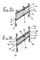
- Fig. 1a and 1b show exemplary of the present invention Faltstoreanlagen 10, 110.
- the upper, stationarily mounted upper rail 12 and a movable rail member 14 are provided.
- a Faltbehang 16 is clamped between the upper rail 12 and the movable rail 14.
- the curtain 16 and the movable rail 14 are stabilized by means of clamping cords 18, wherein the clamping cords 18 are inserted through end caps 20 in the movable rail 14 in this and are guided by Schnurumlenkungen (not shown) in this rail 14 to the upper rail 12.
- a clamping element 22 which is also referred to as a tensioning shoe.
- the clamping elements 22 and the upper rail 12 may for example be fixed to glazing beads of a window frame, wherein between the clamping elements 22 also a cover profile (not shown) may be provided.
- a handle member 24 is provided to change the extension length of the Faltstorebehangs 16 by moving the rail member 14 can.
- a folding gate system 110 two movable rail elements 114 are provided between which in turn the Faltstorebehang 116 is provided.
- the tension cord system is formed in this embodiment so that the ends of the tension cords 118 are fixed to two clamping elements 122 at the lower end of the system and two clamping elements 122 at the upper end of the system, which in turn can be fixed to the upper and lower glass bar of a window frame.
- Both movable rail elements 114 are in turn closed with end caps 120, through which the tensioning cords 118 are guided into the respective rail element 14.
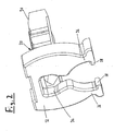
- FIG. 2 an end cap 20 is shown in an oblique view, as in the Faltstorestrom 10 according to Fig. 1 a is used on both sides in the form of a hollow profile movable rail member 14.
- the end caps 120 of the folding gate system 110 according to Fig. 1b corresponds to the illustrated end cap 20 in all details.
- the end cap 20 has a male member 30 which can be inserted for fixing in the hollow profile of the movable rail 14.
- the male member 30 can also serve to fix the piping (not shown), by means of which the Faltstorebehang 16 is fixed to the movable rail 14.
- the end cap 20 has a as a separate part attached to the male member 30 or integrally formed therewith aperture member 32, which has a recess 34 through which the tensioning cord 18 through the end cap 20 from the movable rail member 14 can be brought out.
- one of two legs 36 existing bracket is formed on one side, each having a mutually facing projection 38.
- the two legs 36 are elastically expandable.
- the legs 36 protrude in the direction of the clamping elements on which the tensioning cord 18 is fixed, ie at the in Fig. 1 a shown embodiment, the two legs 36 down.
- end caps 120 of the embodiment according to Fig. 1b The legs of the end caps 120 of the upper movable rail 114 project upward, while the end caps 120 project downward in the lower movable rail 114.
- Fig. 3 is the interaction of the end cap 20 is illustrated with a clamping element 22, as for fixing the Tension cords 18 is used.
- the end cap 20 is shown in a view of the rail element ago and one recognizes a stop surface 40 which limits the insertion path of the end cap 20 when inserted into the hollow profile of the respective movable rail 14.
- a profiled rail can be placed between two clamping elements 22, wherein these are in a tapered portion 44, the clamping element 22 can be placed.
- the movable rail 14 is profiled so that it engages over the clamping elements 22 and an optionally arranged between these profile element, so that a passage of light is locked at the latched with the clamping elements end caps 20.
Landscapes
- Engineering & Computer Science (AREA)
- Structural Engineering (AREA)
- Architecture (AREA)
- Civil Engineering (AREA)
- Curtains And Furnishings For Windows Or Doors (AREA)
Description
- Die vorliegende Erfindung befaßt sich mit einer Sonnenschutzanlage mit einem raffbarem Behang, der zwischen Schienenelementen gehalten ist, von denen wenigstens eines beweglich ist, wobei an Spannelementen festgelegte Spannschnüre zur Führung des wenigstens einen beweglichen Schienenelements vorgesehen sind und das wenigstens eine bewegliche Schienenelement an seinen Enden mit Endkappen versehen ist und die Endkappen mit Rastmitteln versehen sind, die zur Arretierung in der Endstellung mit korrespondierenden Rastmitteln zusammenwirken, die an den Spannelementen ausgebildet sind, und die an den Endkappen vorgesehenen Rastmitteln aus einem Bügel mit zwei Schenkeln bestehen, die die ortsfesten Rastmittel in der arretierten Stellung übergreifen.
- Die Spannschnüre werden in der Regel bei Faltstoren, aber auch bei Falt- und Lamellenjalousien eingesetzt, um diese auch in geneigter oder horizontaler Lage vor entsprechend geneigten Fenstern einsetzen zu können und den Behang gegen Verlagerungen zu stabilisiern.
- Bei solchen Anlagen, die z. B. aus der
DE 93 17 094 U1 bekannt sind, besteht bei Bewegungsschienen in der Endstellung oftmals das Problem der Ausbildung eines störenden Lichtspaltes zwischen der beweglichen Schiene und ihrer Anlagestelle im Bereich der Endposition. Ein solcher Lichtspalt kann sich insbesondere dann einstellen, wenn durch den Behang oder das Schnurspannsystem Kräfte auf die bewegliche Schiene wirken, die bestrebt sind, sie aus ihrer Endposition fortzubewegen. Das Problem tritt insbesondere bei Sonnenschutzanlagen mit zwei beweglichen Schienenelementen auf, zwischen denen der Behang aufgespannt ist, weil in der Regel beim Bedienen einer beweglichen Schiene auch die andere geringfügig verlagert wird. - Aus der
DE 69 06 739 U ist eine Jalousie ohne Schnurführung bekannt, die mit einem Niederhalter in voll ausgefahrener Stellung versehen ist. Dieser dient dazu, eine Bewegung des ansonsten nicht stabilisierten Behangs zu vermeiden. Die Bewegungsschiene muß von unten in den Niederhalter eingeführt werden, d. h. der Behang muß zur Arretierung wieder ein bestimmtes Wegstück nach oben gezogen werden, so daß immer ein Lichtspalt im arretierten Zustand verbleibt. - Bekannt ist auch eine magnetische Arretierung der beweglichen Schiene, wobei allerdings die dazu notwendigen Magnetelemente separat zu montieren sind. Die Magnetkräfte können auch dafür sorgen, daß die bewegliche Schiene unter Umständen bereits in ihre Endstellung gezogen wird, obgleich der Nutzer gerne einen Lichtspalt zwischen der beweglichen Schiene und ihrer Anlagestellung haben möchte.
- Eine Sonnenschutzanlage der eingangs genannten Art ist aus der
US-A-5533559 bekannt. Dort sind die Spannelementen in Flucht mit den Endkappen angeordnet, wobei die Spannelemente aushängbar sind. - Die
EP-A-0195483 beschreibt eine Sonnenschutzanlage mit zwei beweglichen Schienenelementen. - Die Aufgabe der vorliegenden Erfindung besteht darin, eine Sonnenschutzanlage der eingangs genannten Art mit einer Schnurführung von beweglichen Schienenelementen derart zu verbessern, daß die Arretierung in der Endstellung gezielter herstellen läßt.
- Erfindungsgemäß wird die Aufgabe durch eine Sonnenschutzanlage der eingangs beschriebenen Art gelöst, bei welcher die Spannelemente an einer oberen oder unteren Glasleiste festgelegt sind und die Rastmittel an den Spannelementen ortsfest sind, wobei die Schenkel der Endkappe einer oberen beweglichen Schiene nach oben und/oder die Schenkel einer unteren beweglichen Schiene nach unten ragen
- Zum einen wird durch die vorzugsweise formschlüssige Verrastung in einer prinzipbedingt exakten Position eine exakte Schließstellung erreicht. Die Raststellung ist für den Nutzer der in der Regel manuell verschobenen beweglichen Schienen auch gut spürbar, so daß er eine Rückkopplung über das Erreichen der Endstellung erhält. Dagegen ist ein vorzeitiges Springen in die Endstellung ausgeschlossen, da sich die Rastmittel ohne weiteres so ausbilden lassen, daß auf die bewegliche Schiene keine Kräfte in Richtung ihrer Endstellung wirken.
- Ein weiterer Vorteil der erfindungsgemäßen Lösung liegt darin, daß die Rastmittel unmittelbar den Endkappen zugeordnet sind, die ohnehin in die meist hohlen Schienenprofile eingesteckt werden müssen, so daß das bei Magnetelementen zusätzliche Anordnen von Magneten in oder an den Schienen entfallen kann. Dadurch wird die Montage der Sonnenschutzanlage vereinfacht.
- Die Ausbildung der ortsfesten Rastmittel an den ohnehin zu montierenden Spannelementen hat den Vorteil, daß die zusätzliche Funktion ohne Mehraufwand bei der Montage erreicht wird, da auch die Endkappen grundsätzlich bei Profilschienen eingesetzt werden.
- Die Schenkel der Bügel sind vorzugsweise elastisch aufweitbar, was sich bei den in der Regel aus Kunststoff bestehenden Endkappen ohne weiteres realisieren läßt. Alternativ könnten die Schenkel aber auch starr ausgebildet sein, wobei das Einrasten dann in einer Richtung seitlich zur Bewegungsrichtung der Schiene oder durch ausweichende Elemente im Bereich der ortsfesten Rastmittel realisiert werden könnte.
- Im Falle sich beim Erreichen der Endstellung elastisch aufweitender Bügel ist es zweckmäßig, die ortsfesten Rastmittel als einfache Hinterschneidungen auszubilden, in die die Schenkel des Bügels dann einschnappen können.
- Die Spannschnüre können durch die Endkappen in die beweglichen Schienen eingeführt werden. Das Vorsehen von Spannschnüren ist ohnehin bei Anlagen obligatorisch, die zwei bewegliche Schienenelemente vorsehen, zwischen denen der Behang angeordnet ist und die an ihren Endkappen jeweils über Rastmittel zum Zusammenwirken mit ortsfesten Rastmitteln verfügen. Die Spannschnüre sind bei solchen Anlagen über den gesamten Verfahrbereich der beweglichen Schienen gespannt und verlaufen teilweise durch die beweglichen Schienen, um diese zu führen, in beliebiger Stellung durch Reibung zu halten und übermäßige Schrägstellungen zu verhindern. Insbesondere bei sonnenschutzanlagen mit zwei beweglichen Schienenelementen zwischen denen der Behang angeordnet ist, ist die formschlüssige Arretierung des jeweiligen Schienenelements in seiner Endstellung zweckmäßig, um beim Betätigen des anderen Schienenelements eine Verlagerung zu verhindern.
- In der Regel werden die hier in Rede stehenden Sonnenschutzanlagen manuell betätigt, wozu die beweglichen Schienenelemente zweckmäßigerweise über Griffelemente verfügen.
- Ergänzend zu den Spannschnüren können bewegliche Schienenelemente auch in seitlichen Führungsschienen geführt sein, wobei in einer bevorzugten Weiterbildung die Endkappen Führungselemente aufweisen können, die in die Führungsschiene eingreifen. Die Führungsschienen können auch die Funktion haben, einen seitlichen Lichtspalt neben dem Behang zu überdecken.
- Nachfolgend wird anhand der beigefügten Zeichnungen näher auf Ausführungsbeispiele der Erfindung eingegangen. Es zeigen:
- Fig. 1
- eine schematische Ansicht einer Faltstoreanlage mit einem beweglichen Schienenelement;
- Fig. 1 b
- eine Schrägansicht einer Faltstoreanlage mit zwei beweglichen Schienenelementen zwischen denen ein Behang angeordnet ist;
- Fig. 2
- eine Schrägansicht einer Endkappe, wie sie in die beweglichen Schienenelemente gemäß
Fig. 1 a und 1 b eingesetzt ist; - Fig. 3
- Die Endkappe gemäß
Fig. 2 in einer mit einem Spannelement verrasteten Stellung. -
Fig. 1a und 1b zeigen beispielhaft für die vorliegende Erfindung Faltstoreanlagen 10, 110. Bei der inFig. 1 a gezeigten Faltstoreanlage 10 sind die obere, ortsfest montierte Oberschiene 12 sowie ein bewegliches Schienenelement 14 vorgesehen. Ein Faltbehang 16 ist zwischen der Oberschiene 12 und der beweglichen Schiene 14 aufgespannt. Der Behang 16 und die bewegliche Schiene 14 sind mit Hilfe von Spannschnüren 18 stabilisiert, wobei die Spannschnüren 18 durch Endkappen 20 in der beweglichen Schiene 14 in diese eingeführt sind und durch Schnurumlenkungen (nicht gezeigt) in dieser Schiene 14 zur Oberschiene 12 geführt werden. Am unteren Anlagenende sind die Spannschnüre 18 jeweils an einem Spannelement 22 festgelegt, das auch als Spannschuh bezeichnet wird. Die Spannelemente 22 und die Oberschiene 12 können beispielsweise an Glasleisten eines Fensterrahmens festgelegt sein, wobei zwischen den Spannelementen 22 auch noch ein Abdeckprofil (nicht gezeigt) vorgesehen sein kann. - An dem beweglichen Schienenelement 14 ist ein Griffelement 24 vorgesehen, um durch Bewegen des Schienenelements 14 die Ausfahrlänge des Faltstorebehangs 16 verändern zu können.
- Bei der in
Fig. 1 gezeigten Variante einer Faltstoreanlage 110 sind zwei bewegliche Schienenelemente 114 vorgesehen, zwischen den wiederum der Faltstorebehang 116 vorgesehen ist. Das Spannschnursystem ist bei dieser Ausführungsform so ausgebildet, daß die Enden der Spannschnüre 118 an jeweils zwei Spannelementen 122 am unteren Anlagenende und zwei Spannelementen 122 am oberen Anlagenende festgelegt sind, die ihrerseits an der oberen bzw. unteren Glasleiste eines Fensterrahmens festgelegt sein können. Beide beweglichen Schienenelemente 114 sind wiederum mit Endkappen 120 verschlossen, durch die die Spannschnüre 118 in das jeweilige Schienenelement 14 geführt sind. Wiederum erfolgt eine geeignete Umlenkung der Spannschnüre 118 in den Schienen, so daß die Spannschnüre 118 auch zwischen den beiden beweglichen Schienenelementen 114 verlaufen und den Faltstorebehang 116 stabilisieren. Die genaue Ausbildung der Spannschnursysteme ist nicht Gegenstand dieser Anmeldung, so daß hier auf eine nähere Beschreibung der zum Teil sehr komplexen Schnurführung verzichtet werden kann. Da bei der inFig. 1b Ausführungsform auch das obere Schienenelement 114 beweglich ausgeführt ist, verfügt es entsprechend über ein Griffelement 124 zur manuellen Betätigung. - In
Fig. 2 ist in Schrägansicht eine Endkappe 20 gezeigt, wie sie bei der Faltstoreanlage 10 gemäßFig. 1 a beidseitig in das als Hohlprofil ausgebildete bewegliche Schienenelement 14 eingesetzt ist. Die Endkappen 120 der Faltstoreanlage 110 gemäßFig. 1b entspricht der gezeigten Endkappe 20 in allen Details. - Die Endkappe 20 verfügt über ein Einsteckelement 30, das zur Fixierung in das Hohlprofil der beweglichen Schiene 14 einsteckbar ist. Das Einsteckelement 30 kann auch zur Fixierung der Keder dienen (nicht gezeigt), mit Hilfe derer der Faltstorebehang 16 an der beweglichen Schiene 14 festgelegt ist.
- Ferner besitzt die Endkappe 20 ein als separates Teil am Einsteckelement 30 angebrachtes oder einstückig mit diesem ausgebildetes Blendenelement 32, das über eine Ausnehmung 34 verfügt, durch welche die Spannschnur 18 durch die Endkappe 20 aus dem beweglichen Schienenelement 14 herausführbar ist. An dem Blendenelement 32 ist einseitig ein aus zwei Schenkeln 36 bestehender Bügel ausgebildet, die jeweils einen einander zugewandten Vorsprung 38 besitzen. Die beiden Schenkel 36 sind elastisch aufweitbar. Die Schenkel 36 ragen in Richtung der Spannelemente, an denen die Spannschnur 18 festgelegt ist, d. h. bei der in
Fig. 1 a gezeigten Ausführungsform weisen die beiden Schenkel 36 nach unten. Bei den entsprechend ausgeführten Endkappen 120 der Ausführungsform gemäßFig. 1b ragen die Schenkel der Endkappen 120 der oberen beweglichen Schiene 114 nach oben, während die Endkappen 120 in der unteren beweglichen Schiene 114 nach unten ragen. - In
Fig. 3 ist das Zusammenwirken der Endkappe 20 mit einem Spannelement 22 veranschaulicht, wie es zum Festlegen der Spannschnüre 18 eingesetzt wird. Die Endkappe 20 ist in einer Ansicht von dem Schienenelement her gezeigt und man erkennt eine Anschlagfläche 40, die den Einschubweg der Endkappe 20 beim Einstecken in das Hohlprofil der jeweiligen beweglichen Schiene 14 begrenzt. - Aus
Fig. 3 ist ferner zu erkennen, daß die Außenkontur des Spannelements 22 der Innenkontur der beiden Schenkel 36 der Endkappe angepaßt ist, wobei jeweils Hinterschneidungen 42 vorgesehen sind, in welche die Vorsprünge 38 an den Schenkelenden einrasten können. - Zwischen zwei Spannelementen 22 kann gegebenenfalls eine Profilschiene aufgesetzt werden, wobei diese in einem verjüngten Abschnitt 44 das Spannelements 22 aufsetzbar sind.
- Die bewegliche Schiene 14 ist so profiliert, daß sie die Spannelemente 22 und eine gegebenenfalls zwischen diesen angeordnetes Profilelement übergreift, so daß ein Lichtdurchtritt bei mit den Spannelementen verrasteten Endkappen 20 verhindert wird.
- Beim Verrasten wird das jeweilige Schienenelement 14, 114 mit Hilfe des Griffelements 24, 124 in Richtung der Endstellung bewegt, wobei die Schenkel 36 der Endkappen 20 durch die Außenkontur des Spannelements 22 zunächst aufgeweitet werden, bis die Vorsprünge 38 in den Bereich der Hinterschneidungen 42 gelangen, so daß sie in diese Einrasten können. Zum Anheben des Behangs kann wiederum manuell eine Kraft auf die beweglichen Schienenelemente ausgeübt werden, wobei eine Schräge oder Rundung an den Vorsprüngen 38 oder dem oberen Bereich der Hinterschneidungen 42 die Kräfte zum Lösen der Arretierstellung vermindert. Die Verrastung zwischen den Vorsprüngen 38 der Schenkel 36 und den Hinterschneidungen 42 ermöglicht jedoch die Aufnahme aller Kräfte, die beispielsweise bei einer Faltstoreanlage 110 gemäß
Fig. 1b dann auftreten, wenn eine der beiden beweglichen Schienenelemente 114 sich in der verrasteten Endstellung befindet und das andere bewegliche Schienenelement zum weiteren Aufspannen des Behangs von dem arretierten Schienenelement wegbewegt wird.
Claims (8)
- Sonnenschutzanlage mit einem raffbaren Behang (16;116) der zwischen Schienenelementen (12, 14; 114) gehalten ist, von denen wenigstens eines beweglich ist, wobei an Spannelementen (22;122) festgelegte Spannschnüre (18; 118) zur Führung des wenigstens einen beweglichen Schienenelements (114) vorgesehen sind, das bewegliche Schienenelement (14;114) an seinen Enden mit Endkappen (20;120) versehen ist und die Endkappen (20;120) mit Rastmitteln (36,38) versehen sind, die zur Arretierung in der Endstellung mit korrespondierenden Rastmitteln (42) zusammenwirken, die an den Spannelementen (22;122) ausgebildet sind, und die an den Endkappen (20) vorgesehenen Rastmittel (36,38) aus einem Bügel mit zwei Schenkeln (36) bestehen, die die ortsfesten Rastmittel (42) in der arretierten Stellung übergreifen, wobei die Spannschnüre (18;118) das wenigstens eine bewegliche Schienenelement (14;114) in beliebiger Stellung durch Reibung halten, dadurch gekennzeichnet, dass die Spannelemente (22;122) an einer oberen oder unteren Glasleiste festgelegt sind und die Rastmittel (42) an den Spannelementen (22;122) ortsfest sind, wobei entweder die Schenkel (36) der Endkappen einer oberen beweglichen Schiene (114) nach oben und / oder die Schenkel (36) einer unteren beweglichen Schiene (14; 124) nach unten ragen oder die Schenkel (36) der Endkappen einer unteren beweglichen Schiene (14) nach unten ragen.
- Sonnenschutzanlage nach Anspruch 1, dadurch gekennzeichnet, daß der Bügel (36) elastisch aufweitbar ist.
- Sonnenschutzanlage nach Anspruch 1 oder 2, dadurch gekennzeichnet, daß die ortsfesten Rastmittel als Hinterschneidungen (42) ausgebildet sind.
- Sonnenschutzanlage nach einem der vorhergehenden Ansprüche, dadurch gekennzeichnet, daß die Spannschnüre (18; 118) durch die Endkappen (20; 120) in die bewegliche Schiene (14; 114) eingeführt sind.
- Sonnenschutzanlage nach einem der vorhergehenden Ansprüche, dadurch gekennzeichnet, daß zwei bewegliche Schienenelemente (114) vorgesehen sind, zwischen denen der Behang (116) angeordnet ist und die an ihren Endkappen (120) jeweils über Rastmittel (46, 38) zum Zusammenwirken mit ortsfesten Rastmitteln (42) verfügen.
- Sonnenschutzanlage nach einem der vorhergehenden Ansprüche, dadurch gekennzeichnet, daß die bewegliche Schiene (14; 114) über ein Griffelement (124) zum manuellen Betätigen verfügt.
- Sonnenschutzanlage nach einem der vorhergehenden Ansprüche und dadurch gekennzeichnet, daß die bewegliche Schiene (14; 114) in seitlichen Führungsschienen geführt ist.
- Sonnenschutzanlage nach Anspruch 7, dadurch gekennzeichnet, daß die Endkappen Führungselemente aufweisen, die in die jeweilige Führungsschiene eingreifen.
Priority Applications (1)
| Application Number | Priority Date | Filing Date | Title |
|---|---|---|---|
| PL07000235T PL1806471T3 (pl) | 2006-01-07 | 2007-01-08 | Osłona przeciwsłoneczna z ruchomą szyną |
Applications Claiming Priority (1)
| Application Number | Priority Date | Filing Date | Title |
|---|---|---|---|
| DE102006000965A DE102006000965A1 (de) | 2006-01-07 | 2006-01-07 | Bewegungsschienenarretierung |
Publications (3)
| Publication Number | Publication Date |
|---|---|
| EP1806471A2 EP1806471A2 (de) | 2007-07-11 |
| EP1806471A3 EP1806471A3 (de) | 2008-06-18 |
| EP1806471B1 true EP1806471B1 (de) | 2015-05-06 |
Family
ID=37983277
Family Applications (1)
| Application Number | Title | Priority Date | Filing Date |
|---|---|---|---|
| EP20070000235 Not-in-force EP1806471B1 (de) | 2006-01-07 | 2007-01-08 | Sonnenschutzanlage mit Bewegungsschiene |
Country Status (3)
| Country | Link |
|---|---|
| EP (1) | EP1806471B1 (de) |
| DE (1) | DE102006000965A1 (de) |
| PL (1) | PL1806471T3 (de) |
Families Citing this family (1)
| Publication number | Priority date | Publication date | Assignee | Title |
|---|---|---|---|---|
| DE102013111815A1 (de) * | 2013-10-25 | 2015-04-30 | Windhager Handelsgesmbh | Plisseejalousie |
Family Cites Families (7)
| Publication number | Priority date | Publication date | Assignee | Title |
|---|---|---|---|---|
| US3447586A (en) * | 1968-03-15 | 1969-06-03 | Levolor Lorentzen Inc | Venetian-blind hold-down bracket |
| DE6753201U (de) * | 1968-06-07 | 1969-04-10 | Hunter Douglas | Endleiste fuer jalousien |
| DE195483T1 (de) * | 1985-03-13 | 1988-03-17 | Siegfried Joachim Etten-Leur Schoen | Faltjalousie, mehrteilige faltjalousie und verbindungsriegel. |
| DE9110627U1 (de) * | 1991-08-28 | 1991-11-07 | Warema Renkhoff Gmbh & Co Kg, 8772 Marktheidenfeld | Sonnenschutzanlage |
| DE9317094U1 (de) * | 1993-11-09 | 1994-01-27 | MHZ Hachtel GmbH & Co, 70771 Leinfelden-Echterdingen | Vorrichtung zur Befestigung von Schnur- oder Drahtenden |
| US5533559A (en) | 1995-02-06 | 1996-07-09 | Judkins; Ren | Window shade assembly with hold down |
| DE102006013824A1 (de) * | 2005-11-03 | 2007-05-31 | Vkr Holding A/S | Schnurhalter und Endkappe für eine Verschattunganlage sowie Verschattungsanlage |
-
2006
- 2006-01-07 DE DE102006000965A patent/DE102006000965A1/de not_active Withdrawn
-
2007
- 2007-01-08 PL PL07000235T patent/PL1806471T3/pl unknown
- 2007-01-08 EP EP20070000235 patent/EP1806471B1/de not_active Not-in-force
Also Published As
| Publication number | Publication date |
|---|---|
| EP1806471A3 (de) | 2008-06-18 |
| PL1806471T3 (pl) | 2015-10-30 |
| DE102006000965A1 (de) | 2007-07-12 |
| EP1806471A2 (de) | 2007-07-11 |
Similar Documents
| Publication | Publication Date | Title |
|---|---|---|
| WO2014071534A1 (de) | Führungsanordnung für einen behang | |
| DE20204996U1 (de) | Fliegengitter mit Vorrichtung zur Schnellverbindung und -lösung des Griffstabes | |
| EP2826943A1 (de) | Plisseevorhang | |
| DE102011053648A1 (de) | Schnurspanner zum Spannen einer Schnur an Beschattungsanlagen | |
| DE202007014450U1 (de) | Führungsleiste für Fenster und Türen | |
| DE202022106449U1 (de) | Horizontal-Jalousie mit verdeckter Spannschnur | |
| DE102014018562A1 (de) | Verstellbare Abdeckvorrichtung für eine Fläche | |
| DE102013111815A1 (de) | Plisseejalousie | |
| DE102009011914A1 (de) | Plisseesystem | |
| DE202013012570U1 (de) | Rollo | |
| EP1806471A2 (de) | Sonnenschutzanlage mit Bewegungsschiene | |
| DE10362024B4 (de) | Markise, insbesondere zur Verwendung bei einer Pfosten-Riegel-Fassade | |
| EP1783315A2 (de) | Schnurhalter und Endkappe für eine Verschattungsanlage sowie Verschattungsanlage | |
| DE202009015473U1 (de) | Lamellenjalousie | |
| EP1604091A1 (de) | Rolltor | |
| DE202009002646U1 (de) | Raffvorhang | |
| EP3943705B1 (de) | Beschattungsanlage | |
| EP4474610B1 (de) | Schutzvorrichtung für eine gebäudeöffnung und gebäudeöffnung mit einer solchen schutzvorrichtung | |
| EP2920397B1 (de) | Führungsanordnung für einen behang | |
| DE102006062487B4 (de) | Sonnenschutzanlage mit über Endkappen geführtem Schienenprofil | |
| CH707169A1 (de) | Führungsschienenanordnung für einen Behang. | |
| EP4474611A1 (de) | Gebäudeöffnung mit einer schutzvorrichtung | |
| EP2754846B1 (de) | Strangelement, Profilstrang und/oder Verschattungsanlage mit einem solchen Strangelement | |
| DE29714227U1 (de) | Abschirmvorrichtung | |
| DE102006000964A1 (de) | Endkappe für Schienenprofil |
Legal Events
| Date | Code | Title | Description |
|---|---|---|---|
| PUAI | Public reference made under article 153(3) epc to a published international application that has entered the european phase |
Free format text: ORIGINAL CODE: 0009012 |
|
| AK | Designated contracting states |
Kind code of ref document: A2 Designated state(s): AT BE BG CH CY CZ DE DK EE ES FI FR GB GR HU IE IS IT LI LT LU LV MC NL PL PT RO SE SI SK TR |
|
| AX | Request for extension of the european patent |
Extension state: AL BA HR MK YU |
|
| PUAL | Search report despatched |
Free format text: ORIGINAL CODE: 0009013 |
|
| AK | Designated contracting states |
Kind code of ref document: A3 Designated state(s): AT BE BG CH CY CZ DE DK EE ES FI FR GB GR HU IE IS IT LI LT LU LV MC NL PL PT RO SE SI SK TR |
|
| AX | Request for extension of the european patent |
Extension state: AL BA HR MK RS |
|
| 17P | Request for examination filed |
Effective date: 20081218 |
|
| AKX | Designation fees paid |
Designated state(s): AT BE BG CH CY CZ DE DK EE ES FI FR GB GR HU IE IS IT LI LT LU LV MC NL PL PT RO SE SI SK TR |
|
| 17Q | First examination report despatched |
Effective date: 20090205 |
|
| RIC1 | Information provided on ipc code assigned before grant |
Ipc: E06B 9/388 20060101ALI20140210BHEP Ipc: E06B 9/325 20060101AFI20140210BHEP Ipc: E06B 9/327 20060101ALN20140210BHEP |
|
| GRAP | Despatch of communication of intention to grant a patent |
Free format text: ORIGINAL CODE: EPIDOSNIGR1 |
|
| INTG | Intention to grant announced |
Effective date: 20141016 |
|
| RIN1 | Information on inventor provided before grant (corrected) |
Inventor name: KUNKEL, CHRISTIAN Inventor name: SCHAETZLEIN, THOMAS Inventor name: MUELLER, JOACHIM |
|
| GRAS | Grant fee paid |
Free format text: ORIGINAL CODE: EPIDOSNIGR3 |
|
| GRAA | (expected) grant |
Free format text: ORIGINAL CODE: 0009210 |
|
| AK | Designated contracting states |
Kind code of ref document: B1 Designated state(s): AT BE BG CH CY CZ DE DK EE ES FI FR GB GR HU IE IS IT LI LT LU LV MC NL PL PT RO SE SI SK TR |
|
| REG | Reference to a national code |
Ref country code: GB Ref legal event code: FG4D Free format text: NOT ENGLISH |
|
| REG | Reference to a national code |
Ref country code: CH Ref legal event code: EP |
|
| REG | Reference to a national code |
Ref country code: IE Ref legal event code: FG4D Free format text: LANGUAGE OF EP DOCUMENT: GERMAN |
|
| REG | Reference to a national code |
Ref country code: AT Ref legal event code: REF Ref document number: 725845 Country of ref document: AT Kind code of ref document: T Effective date: 20150615 Ref country code: CH Ref legal event code: NV Representative=s name: ISLER AND PEDRAZZINI AG, CH |
|
| REG | Reference to a national code |
Ref country code: DE Ref legal event code: R096 Ref document number: 502007013909 Country of ref document: DE Effective date: 20150618 |
|
| REG | Reference to a national code |
Ref country code: NL Ref legal event code: T3 |
|
| REG | Reference to a national code |
Ref country code: LT Ref legal event code: MG4D |
|
| PG25 | Lapsed in a contracting state [announced via postgrant information from national office to epo] |
Ref country code: ES Free format text: LAPSE BECAUSE OF FAILURE TO SUBMIT A TRANSLATION OF THE DESCRIPTION OR TO PAY THE FEE WITHIN THE PRESCRIBED TIME-LIMIT Effective date: 20150506 Ref country code: PT Free format text: LAPSE BECAUSE OF FAILURE TO SUBMIT A TRANSLATION OF THE DESCRIPTION OR TO PAY THE FEE WITHIN THE PRESCRIBED TIME-LIMIT Effective date: 20150907 Ref country code: FI Free format text: LAPSE BECAUSE OF FAILURE TO SUBMIT A TRANSLATION OF THE DESCRIPTION OR TO PAY THE FEE WITHIN THE PRESCRIBED TIME-LIMIT Effective date: 20150506 Ref country code: LT Free format text: LAPSE BECAUSE OF FAILURE TO SUBMIT A TRANSLATION OF THE DESCRIPTION OR TO PAY THE FEE WITHIN THE PRESCRIBED TIME-LIMIT Effective date: 20150506 |
|
| REG | Reference to a national code |
Ref country code: PL Ref legal event code: T3 |
|
| PG25 | Lapsed in a contracting state [announced via postgrant information from national office to epo] |
Ref country code: LV Free format text: LAPSE BECAUSE OF FAILURE TO SUBMIT A TRANSLATION OF THE DESCRIPTION OR TO PAY THE FEE WITHIN THE PRESCRIBED TIME-LIMIT Effective date: 20150506 Ref country code: BG Free format text: LAPSE BECAUSE OF FAILURE TO SUBMIT A TRANSLATION OF THE DESCRIPTION OR TO PAY THE FEE WITHIN THE PRESCRIBED TIME-LIMIT Effective date: 20150806 Ref country code: IS Free format text: LAPSE BECAUSE OF FAILURE TO SUBMIT A TRANSLATION OF THE DESCRIPTION OR TO PAY THE FEE WITHIN THE PRESCRIBED TIME-LIMIT Effective date: 20150906 Ref country code: GR Free format text: LAPSE BECAUSE OF FAILURE TO SUBMIT A TRANSLATION OF THE DESCRIPTION OR TO PAY THE FEE WITHIN THE PRESCRIBED TIME-LIMIT Effective date: 20150807 |
|
| REG | Reference to a national code |
Ref country code: DE Ref legal event code: R082 Ref document number: 502007013909 Country of ref document: DE Representative=s name: PATENTANWAELTE OLBRICHT, BUCHHOLD, KEULERTZ PA, DE |
|
| PG25 | Lapsed in a contracting state [announced via postgrant information from national office to epo] |
Ref country code: DK Free format text: LAPSE BECAUSE OF FAILURE TO SUBMIT A TRANSLATION OF THE DESCRIPTION OR TO PAY THE FEE WITHIN THE PRESCRIBED TIME-LIMIT Effective date: 20150506 Ref country code: EE Free format text: LAPSE BECAUSE OF FAILURE TO SUBMIT A TRANSLATION OF THE DESCRIPTION OR TO PAY THE FEE WITHIN THE PRESCRIBED TIME-LIMIT Effective date: 20150506 |
|
| REG | Reference to a national code |
Ref country code: DE Ref legal event code: R097 Ref document number: 502007013909 Country of ref document: DE |
|
| PG25 | Lapsed in a contracting state [announced via postgrant information from national office to epo] |
Ref country code: SK Free format text: LAPSE BECAUSE OF FAILURE TO SUBMIT A TRANSLATION OF THE DESCRIPTION OR TO PAY THE FEE WITHIN THE PRESCRIBED TIME-LIMIT Effective date: 20150506 Ref country code: CZ Free format text: LAPSE BECAUSE OF FAILURE TO SUBMIT A TRANSLATION OF THE DESCRIPTION OR TO PAY THE FEE WITHIN THE PRESCRIBED TIME-LIMIT Effective date: 20150506 Ref country code: RO Free format text: LAPSE BECAUSE OF NON-PAYMENT OF DUE FEES Effective date: 20150506 |
|
| PGFP | Annual fee paid to national office [announced via postgrant information from national office to epo] |
Ref country code: PL Payment date: 20151230 Year of fee payment: 10 |
|
| PLBE | No opposition filed within time limit |
Free format text: ORIGINAL CODE: 0009261 |
|
| STAA | Information on the status of an ep patent application or granted ep patent |
Free format text: STATUS: NO OPPOSITION FILED WITHIN TIME LIMIT |
|
| PGFP | Annual fee paid to national office [announced via postgrant information from national office to epo] |
Ref country code: NL Payment date: 20160112 Year of fee payment: 10 |
|
| 26N | No opposition filed |
Effective date: 20160209 |
|
| PG25 | Lapsed in a contracting state [announced via postgrant information from national office to epo] |
Ref country code: IT Free format text: LAPSE BECAUSE OF FAILURE TO SUBMIT A TRANSLATION OF THE DESCRIPTION OR TO PAY THE FEE WITHIN THE PRESCRIBED TIME-LIMIT Effective date: 20150506 |
|
| PGFP | Annual fee paid to national office [announced via postgrant information from national office to epo] |
Ref country code: CH Payment date: 20160112 Year of fee payment: 10 |
|
| PG25 | Lapsed in a contracting state [announced via postgrant information from national office to epo] |
Ref country code: BE Free format text: LAPSE BECAUSE OF NON-PAYMENT OF DUE FEES Effective date: 20160131 Ref country code: SI Free format text: LAPSE BECAUSE OF FAILURE TO SUBMIT A TRANSLATION OF THE DESCRIPTION OR TO PAY THE FEE WITHIN THE PRESCRIBED TIME-LIMIT Effective date: 20150506 |
|
| PGFP | Annual fee paid to national office [announced via postgrant information from national office to epo] |
Ref country code: AT Payment date: 20160119 Year of fee payment: 10 |
|
| PG25 | Lapsed in a contracting state [announced via postgrant information from national office to epo] |
Ref country code: LU Free format text: LAPSE BECAUSE OF FAILURE TO SUBMIT A TRANSLATION OF THE DESCRIPTION OR TO PAY THE FEE WITHIN THE PRESCRIBED TIME-LIMIT Effective date: 20160108 |
|
| GBPC | Gb: european patent ceased through non-payment of renewal fee |
Effective date: 20160108 |
|
| PG25 | Lapsed in a contracting state [announced via postgrant information from national office to epo] |
Ref country code: MC Free format text: LAPSE BECAUSE OF FAILURE TO SUBMIT A TRANSLATION OF THE DESCRIPTION OR TO PAY THE FEE WITHIN THE PRESCRIBED TIME-LIMIT Effective date: 20150506 |
|
| REG | Reference to a national code |
Ref country code: FR Ref legal event code: ST Effective date: 20160930 |
|
| PG25 | Lapsed in a contracting state [announced via postgrant information from national office to epo] |
Ref country code: GB Free format text: LAPSE BECAUSE OF NON-PAYMENT OF DUE FEES Effective date: 20160108 |
|
| REG | Reference to a national code |
Ref country code: IE Ref legal event code: MM4A |
|
| PG25 | Lapsed in a contracting state [announced via postgrant information from national office to epo] |
Ref country code: FR Free format text: LAPSE BECAUSE OF NON-PAYMENT OF DUE FEES Effective date: 20160201 |
|
| PG25 | Lapsed in a contracting state [announced via postgrant information from national office to epo] |
Ref country code: IE Free format text: LAPSE BECAUSE OF NON-PAYMENT OF DUE FEES Effective date: 20160108 |
|
| PG25 | Lapsed in a contracting state [announced via postgrant information from national office to epo] |
Ref country code: SE Free format text: LAPSE BECAUSE OF FAILURE TO SUBMIT A TRANSLATION OF THE DESCRIPTION OR TO PAY THE FEE WITHIN THE PRESCRIBED TIME-LIMIT Effective date: 20150506 |
|
| REG | Reference to a national code |
Ref country code: CH Ref legal event code: PL |
|
| REG | Reference to a national code |
Ref country code: NL Ref legal event code: MM Effective date: 20170201 |
|
| REG | Reference to a national code |
Ref country code: AT Ref legal event code: MM01 Ref document number: 725845 Country of ref document: AT Kind code of ref document: T Effective date: 20170108 |
|
| PG25 | Lapsed in a contracting state [announced via postgrant information from national office to epo] |
Ref country code: AT Free format text: LAPSE BECAUSE OF NON-PAYMENT OF DUE FEES Effective date: 20170108 Ref country code: CH Free format text: LAPSE BECAUSE OF NON-PAYMENT OF DUE FEES Effective date: 20170131 Ref country code: LI Free format text: LAPSE BECAUSE OF NON-PAYMENT OF DUE FEES Effective date: 20170131 |
|
| PG25 | Lapsed in a contracting state [announced via postgrant information from national office to epo] |
Ref country code: NL Free format text: LAPSE BECAUSE OF NON-PAYMENT OF DUE FEES Effective date: 20170201 |
|
| PGFP | Annual fee paid to national office [announced via postgrant information from national office to epo] |
Ref country code: DE Payment date: 20180131 Year of fee payment: 12 |
|
| PG25 | Lapsed in a contracting state [announced via postgrant information from national office to epo] |
Ref country code: CY Free format text: LAPSE BECAUSE OF FAILURE TO SUBMIT A TRANSLATION OF THE DESCRIPTION OR TO PAY THE FEE WITHIN THE PRESCRIBED TIME-LIMIT Effective date: 20150506 Ref country code: HU Free format text: LAPSE BECAUSE OF FAILURE TO SUBMIT A TRANSLATION OF THE DESCRIPTION OR TO PAY THE FEE WITHIN THE PRESCRIBED TIME-LIMIT; INVALID AB INITIO Effective date: 20070108 |
|
| PG25 | Lapsed in a contracting state [announced via postgrant information from national office to epo] |
Ref country code: TR Free format text: LAPSE BECAUSE OF FAILURE TO SUBMIT A TRANSLATION OF THE DESCRIPTION OR TO PAY THE FEE WITHIN THE PRESCRIBED TIME-LIMIT Effective date: 20150506 |
|
| PG25 | Lapsed in a contracting state [announced via postgrant information from national office to epo] |
Ref country code: PL Free format text: LAPSE BECAUSE OF NON-PAYMENT OF DUE FEES Effective date: 20170108 |
|
| REG | Reference to a national code |
Ref country code: DE Ref legal event code: R119 Ref document number: 502007013909 Country of ref document: DE |
|
| PG25 | Lapsed in a contracting state [announced via postgrant information from national office to epo] |
Ref country code: DE Free format text: LAPSE BECAUSE OF NON-PAYMENT OF DUE FEES Effective date: 20190801 |