EP1804388B1 - Digital broadcast reception device - Google Patents
Digital broadcast reception device Download PDFInfo
- Publication number
- EP1804388B1 EP1804388B1 EP05759958.1A EP05759958A EP1804388B1 EP 1804388 B1 EP1804388 B1 EP 1804388B1 EP 05759958 A EP05759958 A EP 05759958A EP 1804388 B1 EP1804388 B1 EP 1804388B1
- Authority
- EP
- European Patent Office
- Prior art keywords
- spectrum
- broadcasting
- signal
- digital broadcasting
- receiving apparatus
- Prior art date
- Legal status (The legal status is an assumption and is not a legal conclusion. Google has not performed a legal analysis and makes no representation as to the accuracy of the status listed.)
- Expired - Lifetime
Links
Images


Classifications
-
- H—ELECTRICITY
- H04—ELECTRIC COMMUNICATION TECHNIQUE
- H04N—PICTORIAL COMMUNICATION, e.g. TELEVISION
- H04N5/00—Details of television systems
- H04N5/44—Receiver circuitry for the reception of television signals according to analogue transmission standards
- H04N5/46—Receiver circuitry for the reception of television signals according to analogue transmission standards for receiving on more than one standard at will
-
- H—ELECTRICITY
- H04—ELECTRIC COMMUNICATION TECHNIQUE
- H04N—PICTORIAL COMMUNICATION, e.g. TELEVISION
- H04N21/00—Selective content distribution, e.g. interactive television or video on demand [VOD]
- H04N21/40—Client devices specifically adapted for the reception of or interaction with content, e.g. set-top-box [STB]; Operations thereof
- H04N21/41—Structure of client; Structure of client peripherals
- H04N21/426—Internal components of the client ; Characteristics thereof
- H04N21/42607—Internal components of the client ; Characteristics thereof for processing the incoming bitstream
- H04N21/4263—Internal components of the client ; Characteristics thereof for processing the incoming bitstream involving specific tuning arrangements, e.g. two tuners
- H04N21/42638—Internal components of the client ; Characteristics thereof for processing the incoming bitstream involving specific tuning arrangements, e.g. two tuners involving a hybrid front-end, e.g. analog and digital tuners
-
- H—ELECTRICITY
- H04—ELECTRIC COMMUNICATION TECHNIQUE
- H04N—PICTORIAL COMMUNICATION, e.g. TELEVISION
- H04N21/00—Selective content distribution, e.g. interactive television or video on demand [VOD]
- H04N21/40—Client devices specifically adapted for the reception of or interaction with content, e.g. set-top-box [STB]; Operations thereof
- H04N21/43—Processing of content or additional data, e.g. demultiplexing additional data from a digital video stream; Elementary client operations, e.g. monitoring of home network or synchronising decoder's clock; Client middleware
- H04N21/438—Interfacing the downstream path of the transmission network originating from a server, e.g. retrieving encoded video stream packets from an IP network
- H04N21/4382—Demodulation or channel decoding, e.g. QPSK demodulation
-
- H—ELECTRICITY
- H04—ELECTRIC COMMUNICATION TECHNIQUE
- H04N—PICTORIAL COMMUNICATION, e.g. TELEVISION
- H04N21/00—Selective content distribution, e.g. interactive television or video on demand [VOD]
- H04N21/40—Client devices specifically adapted for the reception of or interaction with content, e.g. set-top-box [STB]; Operations thereof
- H04N21/43—Processing of content or additional data, e.g. demultiplexing additional data from a digital video stream; Elementary client operations, e.g. monitoring of home network or synchronising decoder's clock; Client middleware
- H04N21/438—Interfacing the downstream path of the transmission network originating from a server, e.g. retrieving encoded video stream packets from an IP network
- H04N21/4383—Accessing a communication channel
-
- H—ELECTRICITY
- H04—ELECTRIC COMMUNICATION TECHNIQUE
- H04N—PICTORIAL COMMUNICATION, e.g. TELEVISION
- H04N21/00—Selective content distribution, e.g. interactive television or video on demand [VOD]
- H04N21/40—Client devices specifically adapted for the reception of or interaction with content, e.g. set-top-box [STB]; Operations thereof
- H04N21/41—Structure of client; Structure of client peripherals
- H04N21/426—Internal components of the client ; Characteristics thereof
- H04N21/42607—Internal components of the client ; Characteristics thereof for processing the incoming bitstream
- H04N21/42623—Internal components of the client ; Characteristics thereof for processing the incoming bitstream involving specific decryption arrangements
Definitions
- the present invention relates to a digital broadcasting receiving apparatus, and particularly to a digital broadcasting receiving apparatus preferably applicable to a case where an analog broadcasting signal and a digital broadcasting signal are mixed together in the same broadcasting frequency band.
- a receiving apparatus receives an analog broadcasting signal by sequentially searching for broadcasting channels to search for a received station (station to be received)
- the receiving apparatus makes a decision as to whether the received signal can undergo sync AFC processing or not according to the presence or absence of the detection of the transmission mode that includes information about scrambling procedure and about the content of the error correcting code at the broadcasting side. Since it is an analog broadcasting signal originally, the transmission mode cannot be detected, and hence the next channel search is started. As a result, sync detection waiting time that is set in the course of this is wasted (see Patent Documents 1 and 2, for example).
- the conventional digital broadcasting receiving apparatus takes considerable time to make a decision that the analog broadcasting signal in the broadcasting band is unreceivable. This presents a problem of impairing usability from a standpoint of a user because of unnecessary prolongation of the operation.
- JP 2003 234975 A relates to a broadcast signal discriminator, aiming at quickly discriminating between broadcast signals with analogue broad waves and those with digital broadcast waves received in a channel during the simultaneous broadcast time period.
- a tuner 12 tunes in the channel specified by a channel search signal and a channel selection output is supplied to a variable filter 13.
- the signal which passed this variable filter 13 is supplied to a power measurement machine 14.
- the power measurement machine 14 measures the electric power within the zone which passed the variable filter 13 according to frequency, and that measurement result is supplied to the decision processing part 15.
- the decision processing part 15 coordinates with the control section 16.
- a power peak value P2 and a power value P1 of the entire band are measured to compare the difference P3 between the peak value P2 and the total power value P1 with a reference value Pref. As a result, it is determined that analogue broadcast waves or digital broadcast waves are received.
- the present invention is implemented to solve the foregoing problem. Therefore it is an object of the present invention to provide a low cost digital broadcasting receiving apparatus capable of improving the usability and convenience of a user by reducing time necessary for making a decision that the analog broadcasting signal or unwanted interference signal existing in a broadcasting band is unreceivable when carrying out the received station search.
- a digital broadcasting receiving apparatus in accordance with the present invention as defined in the claims includes: spectrum analyzing means for analyzing a spectrum of a received signal; spectrum distribution analyzing means for analyzing a distribution profile of the spectrum of the received signal from an output of the spectrum analyzing means; and tuning search control means for carrying out tuning by making a decision as to whether the signal during receiving is a digital broadcasting signal or not in response to an output of the spectrum distribution analyzing means.
- the received station search it is possible for the received station search to reduce the time taken to make a decision that they are unreceivable as to the analog broadcasting or unwanted interference signal in the broadcasting band, thereby being able to improve the usability and convenience of the receiving apparatus for the user.
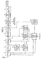
- FIG. 1 is a block diagram showing a configuration of a digital broadcasting receiving apparatus of an embodiment 1 in accordance with the present invention.
- the digital broadcasting receiving apparatus includes an antenna 1 for receiving radio waves in a broadcasting frequency band as electric signals; a tuner 2 for selecting and amplifying a specified broadcasting wave from the signals fed from the antenna 1 by receiving instructions from a tuning search control means 12 which will be described later in response to an operation or the like of a user, and at the same time for converting the selected broadcasting wave to a specified frequency through a superheterodyne or orthogonal demodulation method, followed by outputting it; an A/D converter 3 for converting the analog signal output from the tuner 2 to a digital signal to be output; and a fast Fourier transform means (called “FFT means" from now on) 4 for converting the frequency division multiplexed signal to a plurality of data representing the amplitude and phase of individual carrier waves by applying the fast Fourier transform to the digital broadcasting wave signal, which is transmitted after passing through the orthogonal frequency division multiplexing modulation (OFDM) and is fed from the A/D converter 3.
- OFDM orthogonal frequency division multiple
- the digital broadcasting receiving apparatus includes a descrambling means 5 for restoring, according to a reverse procedure at the time of transmission, the original data sequence of the output data from the FFT means 4, which output data undergo the systematic changes of the sequences between the individual carrier waves and between a plurality of OFDM symbols according to a specific procedure at the time of transmission; an error correcting means 6 for decoding the broadcasting data fed from the descrambling means 5 in the form of error correcting code to the broadcasting data while correcting data errors that can occur on a transmission line by applying the error correcting processing; a signal separating means 7 for reconstructing a series of signals with the same contents by separating information items from the time division multiplexed broadcasting signals obtained by dividing the video signal, audio signal and supplementary information fed from the error correcting means 6 into packet formats with rather short duration; a video audio decoding means 8 for decoding the video signal and audio signal, which are output from the signal separating means 7 in the reconstructed form, to a time-series sampled signal (PCM
- the digital broadcasting receiving apparatus includes a correlation detecting means 10 for detecting correlation peak timing for the present receiving channel fed from the A/D converter 3; an approximate sync AFC control means 11 for supplying a tuning search control means 12 with information as to whether the received signal is a digital broadcasting wave or not by controlling the input data window timing of the FFT means 4 in response to the correlation peak timing detected by the correlation detecting means 10, by correcting the tuner 2 by making estimation of the effect of the frequency detuning on the correlation output, and by making a decision that the correlation peaks appear at certain intervals; a transmission mode detecting means 13 for supplying the tuning search control means 12 with information about the procedure of the scrambling at the broadcasting side and about the error correcting code in response to the output data from the FFT means 4; and an error rate detecting means 14 for supplying the tuning search control means 12 with information as to whether the received signal can present visible and audible video and audio data without problems by detecting the frequency of the errors in the received signal output from the error correcting means 6.
- the digital broadcasting receiving apparatus includes between the FFT means 4 and the tuning search control means 12 a spectrum distribution analyzing means 15 for analyzing the profile of the spectrum distribution by receiving the output of the FFT means 4 that substantially operates as a spectrum analyzing means of the broadcasting signal.
- a first digital broadcasting signal S1 and a second digital broadcasting signal S2 have a trapezoidal shape with substantially uniform spectrum distribution.
- an analog broadcasting signal S3 has such spectrum distribution as having peaks at the video carrier wave and audio carrier wave.
- the spectrum distribution of interference waves that are generated from other digital apparatuses and from an electric circuit of its own, and fall on the broadcasting band it usually has a profile of approximately a line spectrum whose much power concentrates in a rather narrow frequency range.
- the spectrum distribution analyzing means 15 can be constructed in such a manner that it detects whether a rather large peak of the spectrum is present in the broadcasting band or not.
- the tuning search control means 12 can make a decision as to whether the received signal is that of the digital broadcasting or other signals such as of the analog TV broadcasting or interference waves from the output of the spectrum distribution analyzing means 15.
- the processing of the spectrum distribution analyzing means 15 can be considered as an operation of obtaining the numerical value C given by the following expression.
- the numerical value of the peak ratio fed from the spectrum distribution analyzing means 15 is smaller than a predetermined threshold value, a decision is made that it is the digital broadcasting.
- a decision is made that it is other signals such as an analog TV broadcasting signal or interference waves.
- the peak ratio is nearly one for the first and second digital broadcasting signals S1 and S2, and that it is nearly three for the analog broadcasting signal S3.
- the predetermined threshold value (the known threshold value of FIG. 3 ) for making a decision of the digital broadcasting or analog TV broadcasting is set considering these factors.
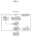
- FIG. 2 is a block diagram showing a concrete circuit configuration of the spectrum distribution analyzing means 15.
- the spectrum distribution analyzing means 15 includes a peak value detecting means 15-2 for detecting a peak value of the output of the FFT means 4, that is, for detecting as to whether a rather large spectrum peak is present in the broadcasting band; a spectrum distribution profile detecting means 15-1 for detecting the average value of the input signal output from the FFT means 4; a calculating means 15-3 for obtaining the peak ratio from the peak value fed from the peak value detecting means 15-2 and the average value fed from the spectrum distribution profile detecting means 15-1; and a comparing means 15-4 for comparing the peak ratio fed from the calculating means 15-3 with the predetermined threshold value stored in a storing means 15-5 in advance, and for supplying the comparing result to the tuning search control means 12 at the next stage.
- a peak value detecting means 15-2 for detecting a peak value of the output of the FFT means 4, that is, for detecting as to whether a rather large spectrum peak is present in the broadcasting band
- a spectrum distribution profile detecting means 15-1 for detecting the average value
- FIG. 5 illustrates operation waveforms when the spectrum distribution analyzing means 15 analyzes the ratio between the spectrum peak value contained in the broadcasting band and the spectrum average value over the entire broadcasting band.
- the symbols a and b denote the peak values of the spectra contained in the broadcasting band
- the symbol c denotes the average value of the spectrum over the entire broadcasting band.
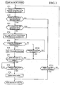
- the tuning search control means 12 increments or decrements the tuning frequency of the tuner 2 by an amount of one channel (step ST1).
- the tuning search control means 12 compares the received signal level (power) with the predetermined threshold value (step ST2), and proceeds to step ST3 when the received signal level exceeds the predetermined threshold value, or to step ST11 otherwise.
- step ST11 a decision is made as to whether the received station search operation (search tuning) has already completed the search of all the channels in the broadcasting band, that is, whether it makes a round of the broadcasting band, and terminates the received station search operation when the round search of the broadcasting band has been completed. On the other hand, unless it has completed the round of the broadcasting band, the processing is returned to step ST1 to change the frequency by an amount of one channel, and continues the search operation of the received station.
- the processing proceeds to step ST11 considering that the present received signal is not that of the digital broadcasting. Unless the round of the broadcasting band has been completed, the processing returns to step ST1 to search for the next channel, and if the round of the broadcasting band has been completed, the received station search operation is completed.
- step ST3 when the output from the spectrum distribution analyzing means 15 is smaller than the fixed threshold value at step ST3, the processing proceeds to step ST4 to start the approximate sync AFC operation by the approximate sync AFC control means 11 in response to the operation of the correlation detecting means 10 for the present receiving channel.
- step ST5 the sync AFC operation for the broadcasting signal is carried out, followed by making a decision as to whether the transmission mode detecting means 13 detects the transmission mode of the received signal correctly or not.
- the processing proceeds to step ST6.
- the time taken by the transmission mode detection is decided at step ST10. If the time exceeds a predetermined value, a decision is made that the signal of the channel is unreceivable, and the processing proceeds to step ST11. Unless the round of the broadcasting band has been completed, the next channel search is carried out, and if the round of the broadcasting band has been completed, the received station search operation is completed.
- the signal separating means 7 separates the video audio signals in response to the supplementary information separated by the separating signal separating means 7, and the video audio decoding means 8 starts the expansion operation of the video audio at step ST6.
- a decision is made as to the information about the data error rate fed from the error rate detecting means 14. If the error rate is greater than the predetermined value, the processing proceeds to step ST11. Unless the round search of the broadcasting band has been completed, the received station search operation is continued, and if the round search has been completed, the received station search operation is completed.
- step ST7 when the error rate fed from the error rate detecting means 14 is smaller than the predetermined value, the processing at step ST8 waits for the completion of the decoding operation of the video and audio signals by the video audio decoding means 8, and the D/A converter 9 carries out the video audio output at step ST9, followed by completing the received station search operation.
- the present embodiment can make a decision as to whether the received signal is that of the digital broadcasting or not without waiting for the decision as to the presence or absence of the detection of the transmission mode, which takes a lot of time. Accordingly, it is possible for the received station search to reduce the time taken to make a decision that they are unreceivable as to the analog broadcasting or unwanted interference signal in the broadcasting band, thereby being able to improve the usability and convenience of the receiving apparatus for the user.
- the present embodiment can reduce the cost by using in common the spectrum analyzing means and one of the receiving circuit means, that is, the FFT means in this case.
- employing the spectrum distribution analyzing means for analyzing the distribution profile of the spectrum of the received signal enables appropriate discrimination of the type of the broadcasting, thereby being able to contribute to the improvement of the broadcasting selecting capability.
- the FFT means for demodulating the orthogonal frequency division multiplexed modulation signal of the broadcasting is used as the spectrum analyzing means, it can be installed independently for exclusive use.
- FIG. 6 is a block diagram showing a configuration of a digital broadcasting receiving apparatus of an embodiment 2 in accordance with the present invention.
- an averaging processing means 16 is provided between the FFT means 4 and the spectrum distribution analyzing means 15 for averaging for each frequency component the output of the FFT means 4 serving as the spectrum analyzing means. Since the remaining configuration is the same as that of FIG. 1 , the description thereof is omitted here.
- the averaging processing in the averaging processing means 16 can substantially be made such processing as is given by the following expression.
- the processing in the spectrum distribution analyzing means 15 can be made such processing as is given by the following expression.
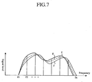
- FIG. 7 is an operation waveform diagram when the averaging processing means 16 carries out averaging for each frequency for a plurality of outputs of the FFT means 4 serving as the spectrum analyzing means.
- symbols e and f each denote the characteristics of the signal levels for the frequency components at the individual frequencies f1 - fn
- the symbol g denotes the characteristics of the signal levels when averaging the individual frequency components of these two outputs, as an example.
- the present embodiment can offer the same advantages as the foregoing embodiment 1.
- a configuration that includes the averaging processing means for averaging the output of the spectrum analyzing means for the individual frequency components, and supplies its output to the spectrum distribution analyzing means can circumvent the malfunction due to pulse noise, thereby being able to offer a higher performance digital broadcasting receiving apparatus free from a malfunction.
- the digital broadcasting receiving apparatus in accordance with the present invention is suitable for improving the usability and convenience of the user by reducing the time taken to make an unreceivable decision in the received station search.
Landscapes
- Engineering & Computer Science (AREA)
- Multimedia (AREA)
- Signal Processing (AREA)
- Circuits Of Receivers In General (AREA)
Applications Claiming Priority (2)
| Application Number | Priority Date | Filing Date | Title |
|---|---|---|---|
| JP2004300424A JP4271121B2 (ja) | 2004-10-14 | 2004-10-14 | デジタル放送受信装置 |
| PCT/JP2005/012861 WO2006040862A1 (ja) | 2004-10-14 | 2005-07-12 | デジタル放送受信装置 |
Publications (3)
| Publication Number | Publication Date |
|---|---|
| EP1804388A1 EP1804388A1 (en) | 2007-07-04 |
| EP1804388A4 EP1804388A4 (en) | 2011-03-30 |
| EP1804388B1 true EP1804388B1 (en) | 2016-04-13 |
Family
ID=36148164
Family Applications (1)
| Application Number | Title | Priority Date | Filing Date |
|---|---|---|---|
| EP05759958.1A Expired - Lifetime EP1804388B1 (en) | 2004-10-14 | 2005-07-12 | Digital broadcast reception device |
Country Status (3)
| Country | Link |
|---|---|
| EP (1) | EP1804388B1 (enExample) |
| JP (1) | JP4271121B2 (enExample) |
| WO (1) | WO2006040862A1 (enExample) |
Families Citing this family (7)
| Publication number | Priority date | Publication date | Assignee | Title |
|---|---|---|---|---|
| JP4949738B2 (ja) * | 2006-05-29 | 2012-06-13 | 富士通セミコンダクター株式会社 | デジタル放送受信機、移動端末およびチャネルサーチ方法 |
| JP4946536B2 (ja) * | 2007-03-13 | 2012-06-06 | 株式会社Jvcケンウッド | アナログ放送受信装置および放送電波受信方法 |
| TR200703666A2 (tr) * | 2007-05-28 | 2008-12-22 | Vestel Elektron�K Sanay� Ve T�Caret A.�. | Kanal kurulum zamanı minimizasyonu için yayın tipi tahminine yönelik metot. |
| CN101682347B (zh) * | 2007-05-30 | 2012-11-21 | 三菱电机株式会社 | 数字广播接收装置 |
| JP2013207766A (ja) * | 2012-03-29 | 2013-10-07 | Pioneer Electronic Corp | 受信装置、放送信号の検出方法、プログラム、および記録媒体 |
| KR20160028128A (ko) * | 2014-09-03 | 2016-03-11 | 삼성전자주식회사 | 방송신호수신장치 및 그 제어방법 |
| IT201900016328A1 (it) * | 2019-09-13 | 2021-03-13 | Elenos S R L | Metodo per la misurazione e la visualizzazione del rapporto segnale/rumore audio |
Family Cites Families (10)
| Publication number | Priority date | Publication date | Assignee | Title |
|---|---|---|---|---|
| JP3241098B2 (ja) * | 1992-06-12 | 2001-12-25 | 株式会社東芝 | 多方式対応の受信装置 |
| JPH077678A (ja) * | 1993-06-18 | 1995-01-10 | Matsushita Electric Ind Co Ltd | 受信装置 |
| JPH07212800A (ja) * | 1994-01-24 | 1995-08-11 | Toshiba Corp | 放送方式判別装置 |
| JP3311150B2 (ja) * | 1994-06-20 | 2002-08-05 | 株式会社東芝 | Tv受像機 |
| KR100213048B1 (ko) * | 1995-09-29 | 1999-08-02 | 윤종용 | 아날로그와 디지탈 비디오 모드를 갖는 수신기와 그 수신방법 |
| JP3777003B2 (ja) * | 1996-12-24 | 2006-05-24 | 富士通テン株式会社 | 選局システム |
| JPH11261913A (ja) * | 1998-03-10 | 1999-09-24 | Sanyo Electric Co Ltd | ディジタル・アナログ共用受信装置 |
| JP3540242B2 (ja) * | 2000-03-30 | 2004-07-07 | 松下電器産業株式会社 | 多方式対応受信装置 |
| JP2003234975A (ja) * | 2002-02-08 | 2003-08-22 | Nippon Television Network Corp | 放送信号識別装置とその方法 |
| US6804191B2 (en) * | 2002-04-05 | 2004-10-12 | Flarion Technologies, Inc. | Phase sequences for timing and access signals |
-
2004
- 2004-10-14 JP JP2004300424A patent/JP4271121B2/ja not_active Expired - Fee Related
-
2005
- 2005-07-12 WO PCT/JP2005/012861 patent/WO2006040862A1/ja not_active Ceased
- 2005-07-12 EP EP05759958.1A patent/EP1804388B1/en not_active Expired - Lifetime
Also Published As
| Publication number | Publication date |
|---|---|
| JP2006115204A (ja) | 2006-04-27 |
| JP4271121B2 (ja) | 2009-06-03 |
| EP1804388A4 (en) | 2011-03-30 |
| EP1804388A1 (en) | 2007-07-04 |
| WO2006040862A1 (ja) | 2006-04-20 |
Similar Documents
| Publication | Publication Date | Title |
|---|---|---|
| US6330293B1 (en) | Method for receiving multicarrier digital signals | |
| EP1618696B1 (en) | Frequency synchronization apparatus and frequency synchronization method | |
| EP0683576A1 (en) | An OFDM digital broadcasting system, and a transmission system and a receiving system used for digital broadcasting | |
| WO1996002990A2 (en) | Method and device for synchronization of transmitter and receiver in a digital system | |
| JPH1174863A5 (enExample) | ||
| US7817738B2 (en) | Digital broadcasting receiving apparatus with channel estimation function | |
| EP1804388B1 (en) | Digital broadcast reception device | |
| KR0152040B1 (ko) | 심볼타이밍복구 및 동기신호검출을 이용한 고선명텔레비젼/엔티에스씨 공용수신방법 및 그 장치 | |
| US8385480B2 (en) | Receiving apparatus and receiving method | |
| EP0895388B1 (en) | Symbol synchronisation and mode detection for multicarrier signals | |
| EP2696581A1 (en) | Receiving device, receiving method, and program | |
| JP2004517511A (ja) | Ofdm信号のパラメータ決定方法及び受信装置 | |
| US6836518B1 (en) | Synchronization control method for receiver apparatus of data transmission system utilizing orthogonal frequency division multiplex, and data transmission system | |
| US8275052B2 (en) | FFT carrier frequency offset estimation for OFDM signal | |
| EP2262248B1 (en) | Method for performing channel scan within a multi-channel broadcasting program receiver, and associated multi-channel broadcasting program receiver | |
| JP2006174218A (ja) | Ofdm受信装置およびofdm受信方法 | |
| JP2003234975A (ja) | 放送信号識別装置とその方法 | |
| US20070201570A1 (en) | OFDM signal receiving apparatus, method of receiving OFDM signal, and digitalized terrestrial broadcast receiving apparatus | |
| WO2001069878A1 (en) | Method of selecting a position of a fft window in a cofdm receiver | |
| JP2008504726A5 (enExample) | ||
| US20110268172A1 (en) | Receiver apparatus and receiving method | |
| EP1755300B1 (en) | Synchronisation in multicarrier receivers | |
| JP2003069907A (ja) | 地上デジタル放送受信装置 | |
| US8238479B2 (en) | Synchronization and acquisition for mobile television reception | |
| JP2004236076A (ja) | 受信装置及び受信方法 |
Legal Events
| Date | Code | Title | Description |
|---|---|---|---|
| PUAI | Public reference made under article 153(3) epc to a published international application that has entered the european phase |
Free format text: ORIGINAL CODE: 0009012 |
|
| 17P | Request for examination filed |
Effective date: 20060613 |
|
| AK | Designated contracting states |
Kind code of ref document: A1 Designated state(s): DE |
|
| DAX | Request for extension of the european patent (deleted) | ||
| RBV | Designated contracting states (corrected) |
Designated state(s): DE |
|
| A4 | Supplementary search report drawn up and despatched |
Effective date: 20110228 |
|
| RIC1 | Information provided on ipc code assigned before grant |
Ipc: H04N 5/46 20060101ALI20110218BHEP Ipc: H04N 5/44 20110101ALI20110218BHEP Ipc: H04B 1/16 20060101AFI20070525BHEP |
|
| 17Q | First examination report despatched |
Effective date: 20110720 |
|
| GRAP | Despatch of communication of intention to grant a patent |
Free format text: ORIGINAL CODE: EPIDOSNIGR1 |
|
| INTG | Intention to grant announced |
Effective date: 20150921 |
|
| GRAS | Grant fee paid |
Free format text: ORIGINAL CODE: EPIDOSNIGR3 |
|
| RIN1 | Information on inventor provided before grant (corrected) |
Inventor name: TAURA, KENICHI Inventor name: OKUMURA, NOBUYOSHI Inventor name: OHKUBO, TADATOSHI Inventor name: ISHIDA, MASAYUKI |
|
| GRAA | (expected) grant |
Free format text: ORIGINAL CODE: 0009210 |
|
| AK | Designated contracting states |
Kind code of ref document: B1 Designated state(s): DE |
|
| REG | Reference to a national code |
Ref country code: DE Ref legal event code: R096 Ref document number: 602005048979 Country of ref document: DE |
|
| REG | Reference to a national code |
Ref country code: DE Ref legal event code: R097 Ref document number: 602005048979 Country of ref document: DE |
|
| PLBE | No opposition filed within time limit |
Free format text: ORIGINAL CODE: 0009261 |
|
| STAA | Information on the status of an ep patent application or granted ep patent |
Free format text: STATUS: NO OPPOSITION FILED WITHIN TIME LIMIT |
|
| 26N | No opposition filed |
Effective date: 20170116 |
|
| REG | Reference to a national code |
Ref country code: DE Ref legal event code: R084 Ref document number: 602005048979 Country of ref document: DE |
|
| PGFP | Annual fee paid to national office [announced via postgrant information from national office to epo] |
Ref country code: DE Payment date: 20200630 Year of fee payment: 16 |
|
| REG | Reference to a national code |
Ref country code: DE Ref legal event code: R119 Ref document number: 602005048979 Country of ref document: DE |
|
| PG25 | Lapsed in a contracting state [announced via postgrant information from national office to epo] |
Ref country code: DE Free format text: LAPSE BECAUSE OF NON-PAYMENT OF DUE FEES Effective date: 20220201 |